Embed Size (px)
Citation preview

990-1062, Revision 1 04 /01
User’s Manual English
APC Smart-UPS®
1000VA/1500VA Tower Unit Uninterruptible Power Supply
230VAC/120VAC

III 990-1062, Revision 1 04/01
TABLE OF CONTENTS
1: Safety Information ................................................................................................................................................................. 1 Handling Safety........................................................................................................................................................................ 1 Electrical Safety ....................................................................................................................................................................... 1 Deenergizing Safety ................................................................................................................................................................. 1 Battery Safety........................................................................................................................................................................... 2 Battery Replacement and Recycling ........................................................................................................................................ 2
2: Installation .............................................................................................................................................................................. 3 Unpacking ................................................................................................................................................................................ 3 Positioning the UPS ................................................................................................................................................................. 3 Installing the Smart-UPS.......................................................................................................................................................... 3 Accessories............................................................................................................................................................................... 4 Disconnecting the Battery for Transport .................................................................................................................................. 4
3: Operation ................................................................................................................................................................................ 5 Smart-UPS Front Panel ............................................................................................................................................................ 5 Smart-UPS Rear Panel ............................................................................................................................................................. 7 On Battery Operation ............................................................................................................................................................... 8
4: User Configurable Items........................................................................................................................................................ 9
5: Storage and Maintenance .................................................................................................................................................... 10 Storage ................................................................................................................................................................................... 10 Replacing the Battery Module................................................................................................................................................ 10
6: Troubleshooting ................................................................................................................................................................... 12 Service.................................................................................................................................................................................... 13 Contacting APC ..................................................................................................................................................................... 13
7: Regulatory and Warranty Information ............................................................................................................................. 14 Regulatory Agency Approvals ............................................................................................................................................... 14 Radio Frequency Interference ................................................................................................................................................ 14 Declaration of Conformity ..................................................................................................................................................... 14 Limited Warranty................................................................................................................................................................... 15
Entire contents copyright © 2001 by American Power Conversion Corporation. All rights reserved. Reproduction in whole or in part without permission is prohibited.
APC, Smart-UPS, and PowerChute are registered trademarks of American Power Conversion Corporation. All other trademarks are the property of their respective owners.

990-1062, Revision 1 04/01 IV
1 990-1062, Revision 1 04/01
1: SAFETY INFORMATION
American Power Conversion Corporation (APC) is the leading national and international manufacturer of state-of-the-art unin-terruptible power supplies, redundant switches, power management software, and related equipment. APC products protect hardware, software, and data from the threat of power disturbances in business and government offices throughout the world.
The APC Uninterruptible Power Supply (UPS) is designed to prevent blackouts, brownouts, sags, and surges from reaching your computer and other valuable electronic equipment. The UPS filters out small utility line fluctuations and isolates your equipment from large disturbances by internally disconnecting from the utility line. The UPS provides continuous power from its internal battery until the utility line returns to safe levels.
Changes or modifications to this unit not expressly approved by the party responsible for compliance could void the warranty.
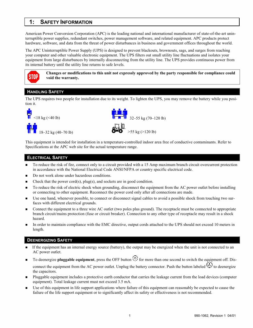
HANDLING SAFETY The UPS requires two people for installation due to its weight. To lighten the UPS, you may remove the battery while you posi-tion it.
<18 kg (<40 lb) 32–55 kg (70–120 lb)
18–32 kg (40–70 lb) >55 kg (>120 lb)
This equipment is intended for installation in a temperature-controlled indoor area free of conductive contaminants. Refer to Specifications at the APC web site for the actual temperature range.
ELECTRICAL SAFETY �� To reduce the risk of fire, connect only to a circuit provided with a 15 Amp maximum branch circuit overcurrent protection
in accordance with the National Electrical Code ANSI/NFPA or country specific electrical code. �� Do not work alone under hazardous conditions. �� Check that the power cord(s), plug(s), and sockets are in good condition. �� To reduce the risk of electric shock when grounding, disconnect the equipment from the AC power outlet before installing
or connecting to other equipment. Reconnect the power cord only after all connections are made. �� Use one hand, whenever possible, to connect or disconnect signal cables to avoid a possible shock from touching two sur-
faces with different electrical grounds. �� Connect the equipment to a three wire AC outlet (two poles plus ground). The receptacle must be connected to appropriate
branch circuit/mains protection (fuse or circuit breaker). Connection to any other type of receptacle may result in a shock hazard.
�� In order to maintain compliance with the EMC directive, output cords attached to the UPS should not exceed 10 meters in length.
DEENERGIZING SAFETY �� If the equipment has an internal energy source (battery), the output may be energized when the unit is not connected to an
AC power outlet.
�� To deenergize pluggable equipment, press the OFF button for more than one second to switch the equipment off. Dis-
connect the equipment from the AC power outlet. Unplug the battery connector. Push the button labeled to deenergize the capacitors.
�� Pluggable equipment includes a protective earth conductor that carries the leakage current from the load devices (computer equipment). Total leakage current must not exceed 3.5 mA.
�� Use of this equipment in life support applications where failure of this equipment can reasonably be expected to cause the failure of the life support equipment or to significantly affect its safety or effectiveness is not recommended.

990-1062, Revision 1 04/01 2
BATTERY SAFETY �� This equipment contains potentially hazardous voltages. Do not attempt to disassemble the unit. The only exception is for
equipment containing batteries. Battery replacement using the procedures below is permissible. Except for the battery, the unit contains no user serviceable parts. Repairs are to be performed only by factory trained service personnel.
�� Do not dispose of batteries in a fire. The batteries may explode. �� Do not open or mutilate batteries. They contain an electrolyte that is toxic and harmful to the skin and eyes. �� Do not connect the terminals of a battery or battery pack with a wire or other electrically conductive objects. �� To avoid personal injury due to energy hazard, remove wristwatches and jewelry such as rings when replacing the batteries.
Use tools with insulated handles. �� Replace batteries with the same number and type of batteries or battery packs as originally installed in the equipment.
BATTERY REPLACEMENT AND RECYCLING See your dealer or visit the APC web site, www.apc.com/support, for information on replacement battery kits and battery recy-cling.
Be sure to return the spent battery to APC for recycling. Ship it to APC in the replacement battery packing ma-terial.
3 990-1062, Revision 1 04/01
2: INSTALLATION
UNPACKING Inspect the UPS upon receipt. APC designed robust packaging for your product. However, accidents and damage may occur during shipment. Notify the carrier and dealer if there is damage.
The packaging is recyclable; save it for reuse or dispose of it properly.
Check the package contents. The package contains the UPS (with battery disconnected), and a literature kit containing one CD, one serial cable, one USB cable, one power cord for the 230V models, and product documentation.
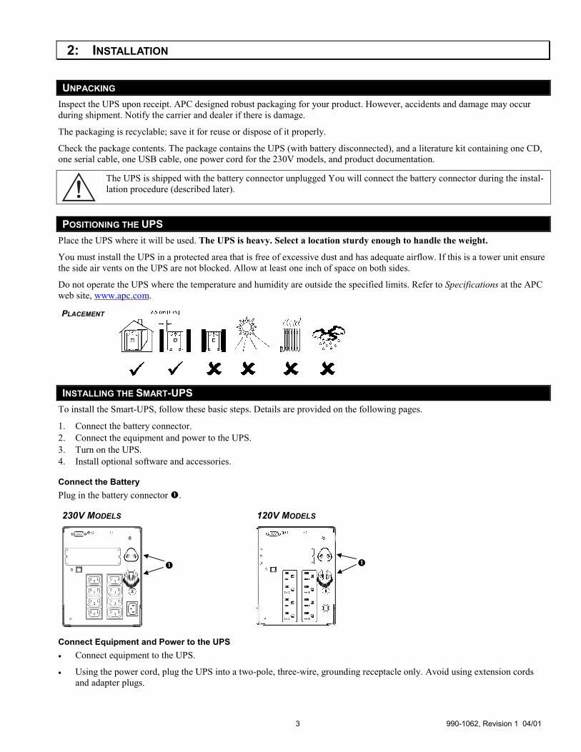
The UPS is shipped with the battery connector unplugged You will connect the battery connector during the instal-lation procedure (described later).
POSITIONING THE UPS Place the UPS where it will be used. The UPS is heavy. Select a location sturdy enough to handle the weight.
You must install the UPS in a protected area that is free of excessive dust and has adequate airflow. If this is a tower unit ensure the side air vents on the UPS are not blocked. Allow at least one inch of space on both sides.
Do not operate the UPS where the temperature and humidity are outside the specified limits. Refer to Specifications at the APC web site, www.apc.com.
PLACEMENT
INSTALLING THE SMART-UPS To install the Smart-UPS, follow these basic steps. Details are provided on the following pages.
1. Connect the battery connector. 2. Connect the equipment and power to the UPS. 3. Turn on the UPS. 4. Install optional software and accessories.
Connect the Battery Plug in the battery connector �.
230V MODELS 120V MODELS
Connect Equipment and Power to the UPS •= Connect equipment to the UPS.
•= Using the power cord, plug the UPS into a two-pole, three-wire, grounding receptacle only. Avoid using extension cords and adapter plugs.
��
990-1062, Revision 1 04/01 4
•= 230V models: The power cord is packaged with the documentation and other cables. Plug the supplied power cord into the inlet on the rear panel of the UPS.
•= 120V models: The power cord is permanently attached to the rear panel of the UPS.
Turn on the UPS
•= Make sure the battery is connected before turning on the UPS! Then, press the button on the front panel to power up your UPS. This will power up connected equipment. (Make sure connected equipment is switched to the ON position.)
The UPS charges its battery when it is connected to utility power. The battery charges fully during the first four hours of normal operation. Do not expect full run time during this initial charge period.
The unit performs a self-test automatically when turned on and every two weeks thereafter (by default). Refer to User Config-urable Items below for details on changing the default interval.
�� 120V Models: Check the site wiring fault indicator located on the rear panel. It lights up if the UPS is plugged into an improperly wired AC power outlet. Wiring faults detected include missing ground, hot-neutral polarity reversal, and overloaded neutral circuit.
If the UPS indicates a site wiring fault, get a qualified electrician to correct the building wiring.
Optional Accessories
Add any optional accessories. See the documentation accompanying the accessory for details.
ACCESSORIES If the UPS is equipped with an accessory slot, visit the APC web site, www.apc.com, for available accessories.
If a standard accessory (such as an SNMP card) is installed on this UPS, see the Utility CD for user documentation.
For additional computer system security, install PowerChutePlus® Smart-UPS monitoring software. It provides automatic unat-tended shutdown capabilities on most major network operating systems.
DISCONNECTING THE BATTERY FOR TRANSPORT
Always DISCONNECT THE BATTERY before shipping in compliance with U.S. Department of Transpor-tation (DOT) regulations. The battery may remain in the UPS; it does not have to be removed.
1. Shut down and disconnect any equipment attached to the UPS.
2. Disconnect the UPS from the power supply.
3. Unplug the battery connector. Refer to Connect the Battery on the previous page.
4. For shipping instructions and to obtain appropriate packing materials contact APC at the web site, www.apc.com/support/contact.
5 990-1062, Revision 1 04/01
3: OPERATION
SMART-UPS FRONT PANEL
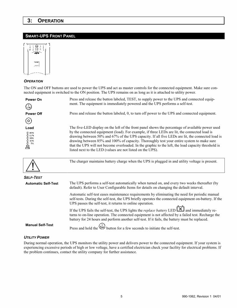
OPERATION The ON and OFF buttons are used to power the UPS and act as master controls for the connected equipment. Make sure con-nected equipment is switched to the ON position. The UPS remains on as long as it is attached to utility power.
Power On
Press and release the button labeled, TEST, to supply power to the UPS and connected equip-ment. The equipment is immediately powered and the UPS performs a self-test.
Power Off
Press and release the button labeled, 0, to turn off power to the UPS and connected equipment.
Load
The five-LED display on the left of the front panel shows the percentage of available power used by the connected equipment (load). For example, if three LEDs are lit, the connected load is drawing between 50% and 67% of the UPS capacity. If all five LEDs are lit, the connected load is drawing between 85% and 100% of capacity. Thoroughly test your entire system to make sure that the UPS will not become overloaded. In the graphic to the left, the load capacity threshold is listed next to the LED (values are not listed on the UPS).
The charger maintains battery charge when the UPS is plugged in and utility voltage is present.
SELF-TEST Automatic Self-Test The UPS performs a self-test automatically when turned on, and every two weeks thereafter (by
default). Refer to User Configurable Items for details on changing the default interval.
Automatic self-test eases maintenance requirements by eliminating the need for periodic manual self-tests. During the self-test, the UPS briefly operates the connected equipment on-battery. If the UPS passes the self-test, it returns to online operation.
If the UPS fails the self-test, the UPS lights the replace battery LED and immediately re-turns to on-line operation. The connected equipment is not affected by a failed test. Recharge the battery for 24 hours and perform another self-test. If it fails, the battery must be replaced.
Manual Self-Test Press and hold the button for a few seconds to initiate the self-test.
UTILITY POWER During normal operation, the UPS monitors the utility power and delivers power to the connected equipment. If your system is experiencing excessive periods of high or low voltage, have a certified electrician check your facility for electrical problems. If the problem continues, contact the utility company for further assistance.
990-1062, Revision 1 04/01 6
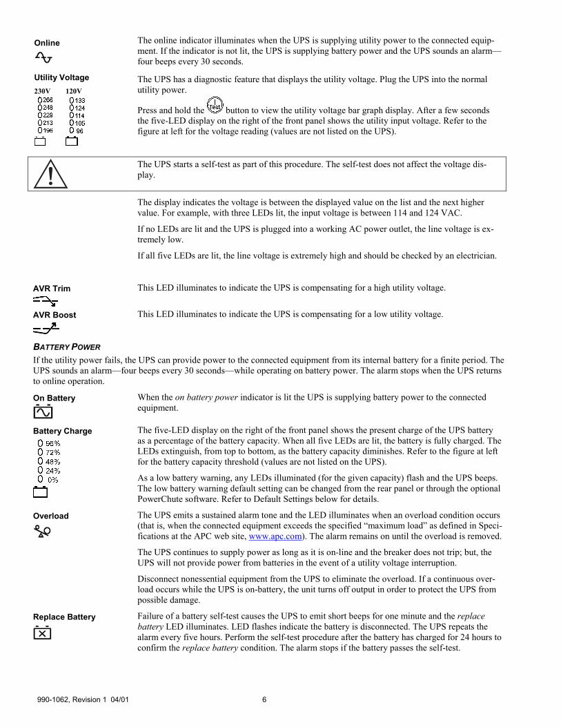
Online
The online indicator illuminates when the UPS is supplying utility power to the connected equip-ment. If the indicator is not lit, the UPS is supplying battery power and the UPS sounds an alarm—four beeps every 30 seconds.
Utility Voltage 230V
120V
The UPS has a diagnostic feature that displays the utility voltage. Plug the UPS into the normal utility power.
Press and hold the button to view the utility voltage bar graph display. After a few seconds the five-LED display on the right of the front panel shows the utility input voltage. Refer to the figure at left for the voltage reading (values are not listed on the UPS).
The UPS starts a self-test as part of this procedure. The self-test does not affect the voltage dis-play.
The display indicates the voltage is between the displayed value on the list and the next higher value. For example, with three LEDs lit, the input voltage is between 114 and 124 VAC.
If no LEDs are lit and the UPS is plugged into a working AC power outlet, the line voltage is ex-tremely low.
If all five LEDs are lit, the line voltage is extremely high and should be checked by an electrician.
AVR Trim
This LED illuminates to indicate the UPS is compensating for a high utility voltage.
AVR Boost
This LED illuminates to indicate the UPS is compensating for a low utility voltage.
BATTERY POWER If the utility power fails, the UPS can provide power to the connected equipment from its internal battery for a finite period. The UPS sounds an alarm—four beeps every 30 seconds—while operating on battery power. The alarm stops when the UPS returns to online operation.
On Battery
When the on battery power indicator is lit the UPS is supplying battery power to the connected equipment.
Battery Charge
The five-LED display on the right of the front panel shows the present charge of the UPS battery as a percentage of the battery capacity. When all five LEDs are lit, the battery is fully charged. The LEDs extinguish, from top to bottom, as the battery capacity diminishes. Refer to the figure at left for the battery capacity threshold (values are not listed on the UPS).
As a low battery warning, any LEDs illuminated (for the given capacity) flash and the UPS beeps. The low battery warning default setting can be changed from the rear panel or through the optional PowerChute software. Refer to Default Settings below for details.
Overload
The UPS emits a sustained alarm tone and the LED illuminates when an overload condition occurs (that is, when the connected equipment exceeds the specified “maximum load” as defined in Speci-fications at the APC web site, www.apc.com). The alarm remains on until the overload is removed.
The UPS continues to supply power as long as it is on-line and the breaker does not trip; but, the UPS will not provide power from batteries in the event of a utility voltage interruption.
Disconnect nonessential equipment from the UPS to eliminate the overload. If a continuous over-load occurs while the UPS is on-battery, the unit turns off output in order to protect the UPS from possible damage.
Replace Battery
Failure of a battery self-test causes the UPS to emit short beeps for one minute and the replace battery LED illuminates. LED flashes indicate the battery is disconnected. The UPS repeats the alarm every five hours. Perform the self-test procedure after the battery has charged for 24 hours to confirm the replace battery condition. The alarm stops if the battery passes the self-test.
7 990-1062, Revision 1 04/01
SHUTDOWN MODE (VIA SOFTWARE OR AN ACCESSORY) In shutdown mode, the UPS stops supplying power to the connected equipment, waiting for the return of utility power. If there is no utility power present, external devices (such as servers) connected to the computer interface or the accessory slot can command the UPS to shut down. This normally is done to preserve battery capacity after the shutdown of protected servers. The UPS scrolls the front panel indicators sequentially in shutdown mode.
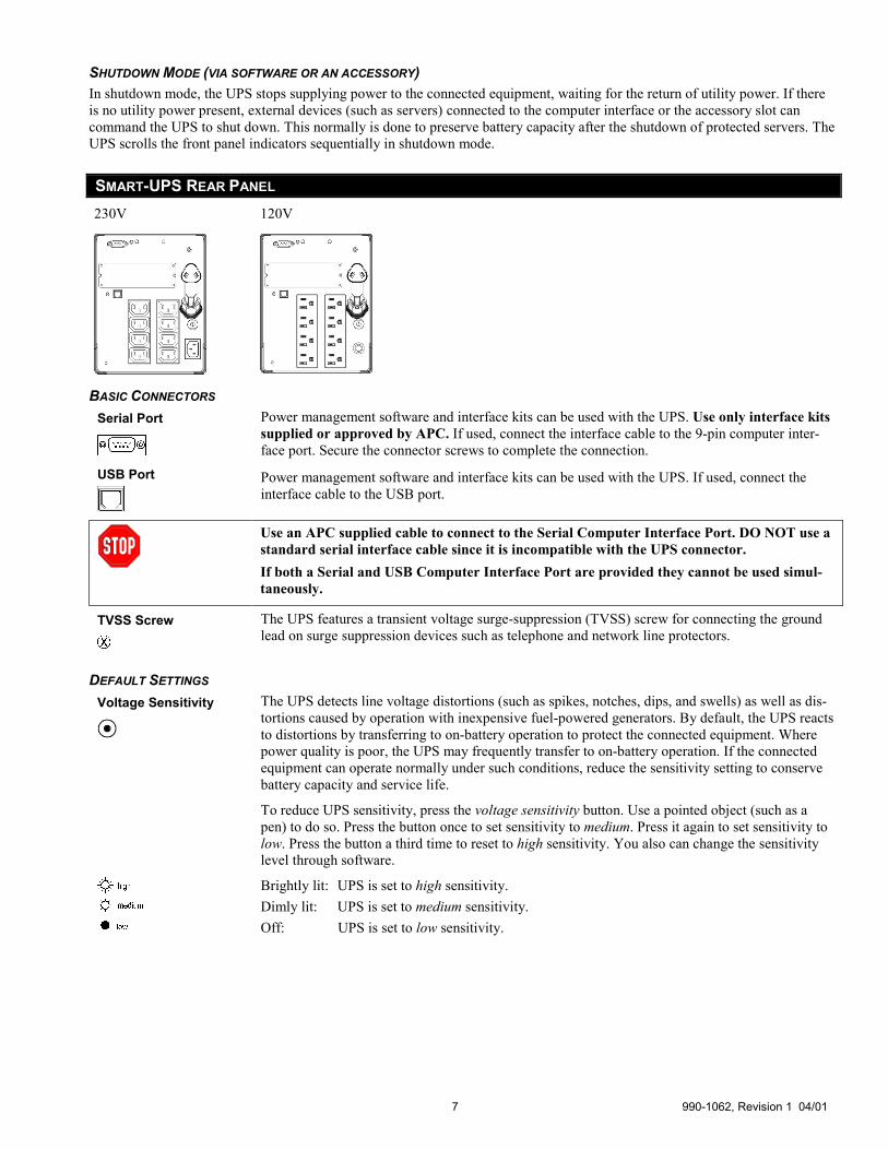
SMART-UPS REAR PANEL 230V 120V
BASIC CONNECTORS Serial Port
Power management software and interface kits can be used with the UPS. Use only interface kits supplied or approved by APC. If used, connect the interface cable to the 9-pin computer inter-face port. Secure the connector screws to complete the connection.
USB Port
Power management software and interface kits can be used with the UPS. If used, connect the interface cable to the USB port.
Use an APC supplied cable to connect to the Serial Computer Interface Port. DO NOT use a standard serial interface cable since it is incompatible with the UPS connector. If both a Serial and USB Computer Interface Port are provided they cannot be used simul-taneously.
TVSS Screw
The UPS features a transient voltage surge-suppression (TVSS) screw for connecting the ground lead on surge suppression devices such as telephone and network line protectors.
DEFAULT SETTINGS Voltage Sensitivity
The UPS detects line voltage distortions (such as spikes, notches, dips, and swells) as well as dis-tortions caused by operation with inexpensive fuel-powered generators. By default, the UPS reacts to distortions by transferring to on-battery operation to protect the connected equipment. Where power quality is poor, the UPS may frequently transfer to on-battery operation. If the connected equipment can operate normally under such conditions, reduce the sensitivity setting to conserve battery capacity and service life.
To reduce UPS sensitivity, press the voltage sensitivity button. Use a pointed object (such as a pen) to do so. Press the button once to set sensitivity to medium. Press it again to set sensitivity to low. Press the button a third time to reset to high sensitivity. You also can change the sensitivity level through software.
Brightly lit: UPS is set to high sensitivity. Dimly lit: UPS is set to medium sensitivity. Off: UPS is set to low sensitivity.

990-1062, Revision 1 04/01 8
Low Battery Warning Level
The low battery warning beeps to indicate low on-battery run time. It beeps periodically (ap-proximately three times per minute) when less than seven minutes of run time remain. The beeps are continuous when only two minutes of run time remain. This may not be enough time to shut down some protected computer systems. To change the warning interval default setting, press the voltage sensitivity button while pressing and holding the front-panel button.
2 min.
5 min.
7 min.
Brightly lit: Low battery warning interval is about two minutes. Dimly lit: Low battery warning interval is about five minutes. Off: Low battery warning interval is about seven minutes.
FAULT INDICATORS Input Circuit Breaker If the plunger on the circuit breaker (located above the input cable connection) pops out, reduce
the load on the UPS by unplugging equipment and press the plunger in.
Unit Circuit Breaker Ratings
1500I 12A
1000I 10A
1500 20A
1000 15A
Site Wiring Fault LED
120V models only: This indicator lights up when the UPS is connected to an improperly wired AC power outlet.
ON BATTERY OPERATION The Smart-UPS switches to battery operation automatically if the utility power fails. While running on-battery, an internal alarm sounds (periodic beeps).
Press the button (front panel) to silence the UPS alarm (for the current alarm only). You can change the audible indicator if you are using the PowerChute software.
If the utility power does not return, the UPS continues to supply power to the connected equipment until exhausted. The UPS will begin to beep continuously approximately two minutes before the UPS final low battery shutdown. If using a computer, you must manually save your files and power down before the UPS turns off, unless you are using PowerChute interface software that provides automatic, unattended shutdown.
DETERMINING ON BATTERY RUN TIME UPS battery life differs based on usage and environment. It is recommended that the battery/batteries are changed once every three years.
See the APC web site, www.apc.com, for on battery run times.

9 990-1062, Revision 1 04/01
4: USER CONFIGURABLE ITEMS
NOTE: SETTING THESE ITEMS REQUIRES SOFTWARE OR OPTIONAL HARDWARE.
FUNCTION FACTORY DEFAULT USER SELECTABLE CHOICES DESCRIPTION
Automatic Self-Test
Every 14 days (336 hours)
Every 7 days (168 hours), On Startup Only, No Self-Test
This function sets the interval at which the UPS will execute a self-test. Refer to your software manual for details.
UPS ID UPS_IDEN Up to eight characters to define the UPS
Use this field to uniquely identify the UPS for network management purposes.
Date of Last Bat-tery Replacement
Manufacture Date
Date of Battery Replacement Reset this date when you replace the battery module.
Minimum Capacity Before Return from Shutdown
0 percent 15, 30, 45, 50, 60, 75, 90 percent The UPS will charge its batteries to the speci-fied percentage before return from a shut-down.
Sensitivity High Medium, Low Set lower than high sensitivity to avoid low-ered battery capacity and service life in situa-tions where the connected equipment can tol-erate minor power disturbances.
Duration of Low Battery Warning
2 minutes 5, 8, 11, 14, 17, 20, 23 minutes This function sets the time before shutdown at which the UPS issues a low battery warning. Set it higher than the default if the operating system needs more time for shutdown.
Alarm Control Enable Mute, Disable User can mute a present ongoing alarm or disable all existing alarms permanently.
Shutdown Delay 90 seconds 0, 180, 270, 360, 450, 540, 630 seconds
This function sets the interval between when the UPS receives a shutdown command and when shutdown occurs.
Synchronized Turn-on Delay
0 seconds 60, 120, 180, 240, 300, 360, 420 seconds
The UPS will wait the specified time after the return of utility power before turn-on (for example, to avoid branch circuit overload).
High Transfer Point 230V models:
253VAC
120V models:
127VAC
230V models:
257, 261,265VAC
120V models:
130, 133,136VAC
To avoid unnecessary battery usage, set the high transfer point higher if the utility voltage is chronically high and the connected equip-ment is known to work under this condition.
Low Transfer Point 230V models:
208VAC
120V models:
106VAC
230V models:
204, 200, 196VAC
120V models:
103, 100, 97VAC
Set the low transfer point lower if the utility voltage is chronically low and the connected equipment can tolerate this condition.
Output Voltage 230V models:
230VAC
230V models:
220, 240VAC
230V models ONLY, allow the user to select the output voltage.
990-1062, Revision 1 04/01 10
5: STORAGE AND MAINTENANCE
STORAGE
STORAGE CONDITIONS Store the UPS covered and positioned as for proper functioning, in a cool, dry location, with its batteries fully charged. Discon-nect any cables connected to the computer interface port to avoid unnecessary battery drainage.
EXTENDED STORAGE At -15 to +30 °C (+5 to +86 °F), charge the UPS battery every six months. At +30 to +45 °C (+86 to +113 °F), charge the UPS battery every three months.
REPLACING THE BATTERY MODULE This UPS has an easy to replace, hot-swappable battery module. Replacement is a safe procedure, isolated from electrical haz-ards. You may leave the UPS and connected equipment on for the following procedure. See your dealer or contact APC for in-formation on replacement battery modules.
Once the battery is disconnected, the loads are not protected from power outages.
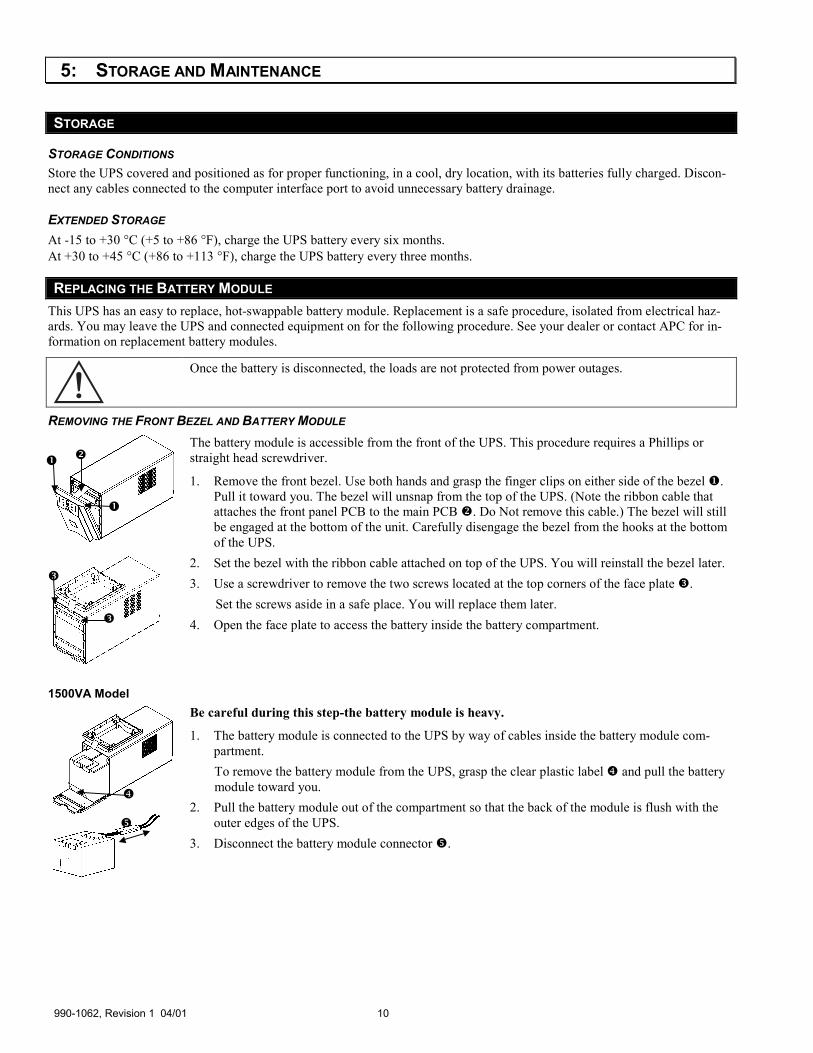
REMOVING THE FRONT BEZEL AND BATTERY MODULE
The battery module is accessible from the front of the UPS. This procedure requires a Phillips or straight head screwdriver.
1. Remove the front bezel. Use both hands and grasp the finger clips on either side of the bezel �. Pull it toward you. The bezel will unsnap from the top of the UPS. (Note the ribbon cable that attaches the front panel PCB to the main PCB �. Do Not remove this cable.) The bezel will still be engaged at the bottom of the unit. Carefully disengage the bezel from the hooks at the bottom of the UPS.
2. Set the bezel with the ribbon cable attached on top of the UPS. You will reinstall the bezel later. 3. Use a screwdriver to remove the two screws located at the top corners of the face plate �.
Set the screws aside in a safe place. You will replace them later. 4. Open the face plate to access the battery inside the battery compartment.
1500VA Model Be careful during this step-the battery module is heavy.
1. The battery module is connected to the UPS by way of cables inside the battery module com-partment. To remove the battery module from the UPS, grasp the clear plastic label � and pull the battery module toward you.
2. Pull the battery module out of the compartment so that the back of the module is flush with the outer edges of the UPS.
3. Disconnect the battery module connector �.
�
��
�
�
�
�
11 990-1062, Revision 1 04/01
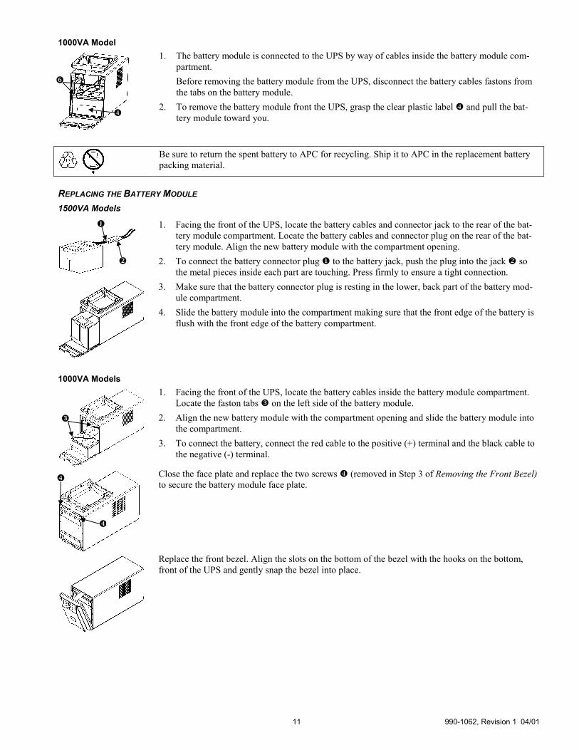
1000VA Model
1. The battery module is connected to the UPS by way of cables inside the battery module com-partment. Before removing the battery module from the UPS, disconnect the battery cables fastons from the tabs on the battery module.
2. To remove the battery module front the UPS, grasp the clear plastic label � and pull the bat-tery module toward you.
Be sure to return the spent battery to APC for recycling. Ship it to APC in the replacement battery packing material.
REPLACING THE BATTERY MODULE 1500VA Models
1. Facing the front of the UPS, locate the battery cables and connector jack to the rear of the bat-tery module compartment. Locate the battery cables and connector plug on the rear of the bat-tery module. Align the new battery module with the compartment opening.
2. To connect the battery connector plug � to the battery jack, push the plug into the jack � so the metal pieces inside each part are touching. Press firmly to ensure a tight connection.
3. Make sure that the battery connector plug is resting in the lower, back part of the battery mod-ule compartment.
4. Slide the battery module into the compartment making sure that the front edge of the battery is flush with the front edge of the battery compartment.
1000VA Models
1. Facing the front of the UPS, locate the battery cables inside the battery module compartment. Locate the faston tabs � on the left side of the battery module.
2. Align the new battery module with the compartment opening and slide the battery module into the compartment.
3. To connect the battery, connect the red cable to the positive (+) terminal and the black cable to the negative (-) terminal.
Close the face plate and replace the two screws � (removed in Step 3 of Removing the Front Bezel) to secure the battery module face plate.
Replace the front bezel. Align the slots on the bottom of the bezel with the hooks on the bottom, front of the UPS and gently snap the bezel into place.
�
�
�
�
�
�
�

990-1062, Revision 1 04/01 12
6: TROUBLESHOOTING Use the chart below to solve minor Smart-UPS installation and operation problems. Refer to the APC web site, www.apc.com, for assistance with complex UPS problems.
PROBLEM AND POSSIBLE CAUSE SOLUTION UPS WILL NOT TURN ON ON button not pushed. Press the ON button once to power the UPS and the connected equipment.
UPS not connected to AC power supply.
Check that the power cable from the UPS to the utility power supply is securely con-nected at both ends.
UPS input circuit breaker tripped. Reduce the load on the UPS by unplugging equipment and resetting the circuit breaker (on the back of UPS) by pressing the plunger in.
Very low or no utility voltage. Check the AC power supply to the UPS by plugging in a table lamp. If the light is very dim, have the utility voltage checked.
Battery not connected properly. Check that the battery connectors are fully engaged.
UPS WILL NOT TURN OFF Internal UPS fault. Do not attempt to use the UPS. Unplug the UPS and have it serviced immediately.
UPS OPERATES ON BATTERY ALTHOUGH NORMAL LINE VOLTAGE EXISTS UPS input circuit breaker tripped. Reduce the load on the UPS by unplugging equipment and resetting the circuit breaker
(on the back of UPS) by pressing the plunger in.
Very high, low, or distorted line voltage. Inexpensive fuel powered generators can distort the voltage.
Move the UPS to a different outlet on a different circuit. Test the input voltage with the utility voltage display. If acceptable to the connected equipment, reduce the UPS sensi-tivity.
UPS BEEPS OCCASIONALLY Normal UPS operation. None. The UPS is protecting the connected equipment.
UPS DOES NOT PROVIDE EXPECTED BACKUP TIME The UPS battery is weak due to a recent outage or is near the end of its service life.
Charge the battery. Batteries require recharging after extended outages. They wear faster when put into service often or when operated at elevated temperatures. If the bat-tery is near the end of its service life, consider replacing the battery even if the replace battery LED indicator is not yet lit.
ALL INDICATORS ARE LIT AND THE UPS EMITS A CONSTANT BEEPING Internal UPS fault. Do not attempt to use the UPS. Turn the UPS off and have it serviced immediately.
The UPS is overloaded. Check the UPS load display. Unplug unnecessary equipment, such as printers.
FRONT PANEL INDICATORS FLASH SEQUENTIALLY The UPS has been shut down re-motely through software or an op-tional accessory card.
None. The UPS will restart automatically when utility power returns.
ALL INDICATORS ARE OFF AND THE UPS IS PLUGGED INTO A WALL OUTLET The UPS is shut down and the bat-tery is discharged from an extended outage.
None. The UPS will return to normal operation when the power is restored and the bat-tery has a sufficient charge.
THE REPLACE BATTERY LED IS LIT Weak battery. Allow the battery to recharge for at least four hours. Then, perform a self-test. If the
problem persists after recharging, replace the battery.
Replacement battery not connected properly.
Check that the battery connectors are fully engaged.

13 990-1062, Revision 1 04/01
SERVICE If the UPS requires service do not return it to the dealer. Instead, follow these steps:
1. Review the problems discussed in the Troubleshooting section of this manual to eliminate common problems. 2. Verify that no circuit breakers are tripped. A tripped circuit breaker is the most common UPS problem. 3. If the problem persists, contact APC Customer Service through the APC web site, www.apc.com/support.
�� Note the model number of the UPS, the serial number, and the date purchased. If you call APC Customer Service, a technician will ask you to describe the problem and try to solve it over the phone, if possible. If this is not possible, the technician will issue a Returned Material Authorization Number (RMA#).
�� If the UPS is under warranty, repairs are free. If not, there is a repair charge. 4. Pack the UPS in its original packaging. If the original packing is not available, refer to the APC web site,
www.apc.com/support, for information about obtaining a new set. �� Pack the UPS properly to avoid damage in transit. Never use Styrofoam beads for packaging. Damage sustained in tran-
sit is not covered under warranty.
Always DISCONNECT THE BATTERY before shipping in compliance with U.S. Department of Transpor-tation (DOT) regulations. The battery may remain in the UPS; it does not have to be removed.
5. Mark the RMA# on the outside of the package. 6. Return the UPS by insured, prepaid carrier to the address given to you by Customer Service.
CONTACTING APC Refer to the information provided at the APC Internet site,
http://www.apc.com/support.
990-1062, Revision 1 04/01 14
7: REGULATORY AND WARRANTY INFORMATION
REGULATORY AGENCY APPROVALS
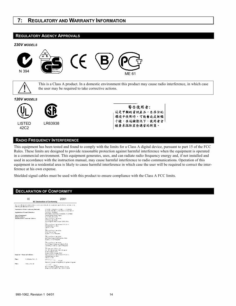
230V MODELS
This is a Class A product. In a domestic environment this product may cause radio interference, in which case the user may be required to take corrective actions.
120V MODELS
RADIO FREQUENCY INTERFERENCE This equipment has been tested and found to comply with the limits for a Class A digital device, pursuant to part 15 of the FCC Rules. These limits are designed to provide reasonable protection against harmful interference when the equipment is operated in a commercial environment. This equipment generates, uses, and can radiate radio frequency energy and, if not installed and used in accordance with the instruction manual, may cause harmful interference to radio communications. Operation of this equipment in a residential area is likely to cause harmful interference in which case the user will be required to correct the inter-ference at his own expense.
Shielded signal cables must be used with this product to ensure compliance with the Class A FCC limits.
DECLARATION OF CONFORMITY
ME 61 N 394
LISTED 42C2
LR63938
15 990-1062, Revision 1 04/01
LIMITED WARRANTY American Power Conversion (APC) warrants its products to be free from defects in materials and workmanship for a period of two years from the date of purchase. Its obligation under this warranty is limited to repairing or replacing, at its own sole option, any such defective products. To obtain service under warranty you must obtain a Returned Material Authorization (RMA) num-ber from customer support. Products must be returned with transportation charges prepaid and must be accompanied by a brief description of the problem encountered and proof of date and place of purchase. This warranty does not apply to equipment that has been damaged by accident, negligence, or misapplication or has been altered or modified in any way. This warranty applies only to the original purchaser who must have properly registered the product within 10 days of purchase.
EXCEPT AS PROVIDED HEREIN, AMERICAN POWER CONVERSION MAKES NO WARRANTIES, EXPRESSED OR IMPLIED, INCLUDING WARRANTIES OF MERCHANTABILITY AND FITNESS FOR A PARTICULAR PURPOSE. Some states do not permit limitation or exclusion of implied warranties; therefore, the aforesaid limitation(s) or exclusion(s) may not apply to the purchaser.
EXCEPT AS PROVIDED ABOVE, IN NO EVENT WILL APC BE LIABLE FOR DIRECT, INDIRECT, SPECIAL, INCI-DENTAL, OR CONSEQUENTIAL DAMAGES ARISING OUT OF THE USE OF THIS PRODUCT, EVEN IF ADVISED OF THE POSSIBILITY OF SUCH DAMAGE. Specifically, APC is not liable for any costs, such as lost profits or revenue, loss of equipment, loss of use of equipment, loss of software, loss of data, costs of substitutes, claims by third parties, or otherwise.