Embed Size (px)
Citation preview

APC Silcon10-80kW 400V Battery CabinetInstallation Guide
Copyright ©2002 APC Denmark ApS
This manual is subject to change without notice and does not represent
a commitment on the part of the vendor.
2 Installation Guide APC Silcon 10-80kW 400V – Battery Cabinet
990-4023A_REV02
IMPORTANT SAFETY INSTRUCTIONS
SAVE THESE INSTRUCTIONS
This manual contains important instructions for your APC Silcon UPS that should be followed during installation and
maintenance of the UPS and batteries.
APC Silcon products are continously developed, and documentation is therefore subject to change without notice.
The installation and use of this product must comply with all national, federal, state, municipal or local codes. If you need assistance, please have your UPS model and serial number ready and call APC's toll free technical support on: +353 91 702000.
You can find additional product information on the APC World Wide Web site at http://www.apcc.com. See Section 2.0: How to Contact APC
WARNING!
With reference to local code use:1. Additional insulating material2. Insulating tool
a) The servicing of batteries requires battery knowledge and should be carried out/supervised by qualified electricians familiar with batteries.Keep unauthorized personnel away from batteries.
b) Use identical battery types and numbers when replacing batteries. See battery supplier manual for further details.
c)
CAUTION
– Do not dispose of batteries in a fire. The batteries may explode.
d)
CAUTION
– Avoid rough treatment and opening of batteries. Released electrolyte is harmful to skin and eyes, and may be toxic.
e)
CAUTION
– Batteries may cause electric shocks and high voltage short-circuit current. Follow the precautions below when working with batteries:
1. Remove watches, rings, or other metal objects.
2. Use tools with insulated handles.
3. Wear rubber gloves and boots.
4. Do not leave tools or metal parts on top of batteries.
5. Disconnect charging source prior to connecting or disconnecting batteries.
6. Determine if the battery is inadvertently grounded. If inadvertently grounded,remove ground source. Any contact with a grounded battery may result in electric shocks. The likelihood of such shocks will be reduced if ground connections are removed during installation and maintenance.

990-4023A_REV02
Installation Guide APC Silcon 10-80kW 400V – Battery Cabinet 3
Contents:
1.0 APC Silcon Battery Cabinet 5
1.1 Safety - Warnings 51.2 Dimensions / Weights 51.3 Footprint (measurements in mm) 61.4 Unpacking and Placing 71.4.1 Preparation 71.4.2 Battery Cabinet Installed Next to UPS 81.4.3 Battery Cabinet Installed Away From UPS 91.5 Terminals 101.6 Before Starting Up 111.6.1 Connecting the APC Silcon UPS and the APC Silcon Battery Cabinet 111.7 Parallel Connection (÷XRI and ÷XR2 cabinets) 13
2.0 How to Contact APC 143.0 Appendix 15
3.1 Appendix – SLB40K60H1 Battery Cabinet Cabling Diagram 153.2 Appendix – SLB40K60H1, Schematic 163.3 Appendix – SLB40K60H1, Electrical Configuration (dimension in mm) 173.4 Appendix – SLB40K60H2 Battery Cabinet, Cabling Diagram 183.5 Appendix – SLB40K60H2 Battery Cabinet Electrical Schematic 193.6 Appendix – SLB40K60H2 Battery Cabinet Electrical (dimensions in mm) 203.7 Appendix - SLB10K80HXR1 Battery Cabinet Cabling Diagram 213.8 Appendix – SLB10K80HXR2, Electrical Configuration (dimensions in mm) 223.9 Appendix – SLB10K80HXR2 Battery Cabinet Cabling Diagram 233.10 Appendix – SLB10K80HXR1, Electrical Configuration (dimensions in mm) 243.11 Appendix – SLB40K60H1+HXR1 Battery Cabinet, Cabling Diagram 253.12 Appendix – SLB40K60H1+HXR1 Battery Cabinet Electrical Schematic 263.13 Appendix – SLB40K60H1+HXR1 Battery Cabinet Electrical
(dimensions in mm) 273.14 Appendix – SLB40K60H2+HXR2 Battery Cabinet, Cabling Diagram 283.15 Appendix – SLB40K60H2+HXR2 Battery Cabinet, Electrical Schematic 293.16 Appendix – SLB40K60H2+HXR2 Battery Cabinet, Electrical,
(dimensions in mm) 303.17 Appendix – SLB80KH1 Battery Cabinet, Cabling Diagram 313.18 Appendix – SLB80KH1 Battery Cabinet, Electrical Schematic 323.19 Appendix – SLB80KH1 Battery Cabinet, Electrical (dimensions in mm) 333.20 Appendix – SLB80KH2 Battery Cabinet, Cabling Diagram 343.21 Appendix – SLB80KH2 Battery Cabinet, Electrical Schematic 353.22 Appendix – SLB80KH2 Battery Cabinet, Electrical (dimensions in mm) 363.23 Appendix – SLB80KH1+HXR1 Battery Cabinet, Cabling Diagram 373.24 Appendix – SLB80KH1+HXR1 Battery Cabinet, Electrical Schematic 383.25 Appendix – SLB80KH1+HXR1 Battery Cabinet Electrical
(dimensions in mm) 393.26 Appendix – SLB80KH2+HXR2 Battery Cabinet, Cabling Diagram 403.27 Appendix – SLB80KH2+HXR2 Battery Cabinet, Electrical Schematic 413.28 Appendix – SLB80KH2+HXR2 Battery Cabinet Electrical
(dimensions in mm) 423.29 Appendix – SLB80KH6 Battery Cabinet, Cabling Diagram 433.30 Appendix – SLB80KH6 Electrical Schematic 443.31 Appendix – SLB80KH6 Battery Cabinet Electrical (dimensions in mm) 45

4 Installation Guide APC Silcon 10-80kW 400V – Battery Cabinet
990-4023A_REV02

APC Silcon Battery Cabinet
990-4023A_REV02
Installation Guide APC Silcon 10-80kW 400V – Battery Cabinet 5
1.0 APC Silcon Battery Cabinet
1.1 Safety - Warnings
1.2 Dimensions / Weights
WARNINGS!
The UPS system contains
HAZARDOUS AC/DC VOLTAGES
and is supplied from several power sources. Some terminals and components are live even when the system is switched off!
ONLY
qualified electricians are allowed to carry out the installation according to national and local codes!
NO
APC Silcon UPS systems may be fitted with built-in batteries when connected to external batteries!
Do
NOT
install the Battery Cabinet and operate battery breakers without referring to this Installation Guide.
SKU Number Runtime [minutes] Dimension(WxDxH) [mm]
Weight[kg]
SLB40K60H1 27 min. for 40kW or 15 min. for 60kW UPS 1270x800x1410 1170
SLB40K60H2 44 min. for 40kW or 26 min. for 60kW UPS 1270x800x1410 1430
SLB80KH1 9 min. runtime for 80kW UPS 1270x800x1410 1170
SLB80KH2 17 min. runtime for 80kW UPS 1270x800x1410 1430
SLB80KH6-2C 57 min. runtime for 80kW UPS 2540x800x1410 3720
SLB10k80HXR1 Extended runtime for 10-80kW UPS 1270x800x1410 1170
SLB10k80HXR2 Extended runtime for 10-80kW UPS 1270x800x1410 1430

6 Installation Guide APC Silcon 10-80kW 400V – Battery Cabinet
990-4023A_REV02
APC Silcon Battery Cabinet
1.3 Footprint (measurements in mm)
234
800
126498
98
98
152
579
586305
Front
Bottom Gland Plate
Note: Dimensions include side covers, rear covers and front doors

APC Silcon Battery Cabinet
990-4023A_REV02
Installation Guide APC Silcon 10-80kW 400V – Battery Cabinet 7
1.4 Unpacking and Placing
1.4.1 Preparation
Unpack the battery cabinet by removing the packaging material. When installing the APC Silcon Battery Cabinet to the UPS, take special care not to cause a short in the battery cabinet. Transport the battery cabinet to the installation site by lifting underneath with a forklift.
It is recommended to place the cabinet directly to the left of the UPS, and to bolt the units together. Refer to 1.4.2 for procedure. The battery cabinet can also be placed away from the UPS. Refer to 1.4.3 for procedure. Cables are routed through an opening on the bottom of the cabinet, which is covered by a gland plate. However, separating the battery cabinet from the UPS can effect the runtime, because the inter-cabinet cables can increase system resistance. Distance between the cabinet and UPS should be minimized. After placing the cabinet, open the doors and remove the dead front panel for access to the gland plate and external connections. Note image below.
CAUTION!
Take note of product weight. Center of gravity is not directly in the middle. APC Recommends lifting from the left side, underthe cabinet frame, with forks long enough to support all three legs.

8 Installation Guide APC Silcon 10-80kW 400V – Battery Cabinet
990-4023A_REV02
APC Silcon Battery Cabinet
1.4.2 Battery Cabinet Installed Next to UPS
Position the UPS and remove the two left UPS cover plates (fixed with screws on the inside of the UPS cabinet as shown below).
Remove the right side panel of the battery cabinet. Place the cabinet to the left of the UPS, lining up the sides evenly. Bolt the cabinet to the UPS with the enclosed rails and bolts.
If the battery solution includes more than one cabinet , i.e an XR Battery Cabinet is to be installed, remove the left side access panel of the battery Cabinet. Line up the XR Battery Cabinet to the left of the Battery Cabinet and connect the flying Anderson leads from the XR Battery Cabinet into the Anderson connectors located on the Battery Cabinet. Enough room need to be left between the Battery XR Cabinet and the Battery Cabinet to accommodate the flying leads.
Left side view of UPS without cover plate
APC Silcon Battery Cabinet
990-4023A_REV02
Installation Guide APC Silcon 10-80kW 400V – Battery Cabinet 9
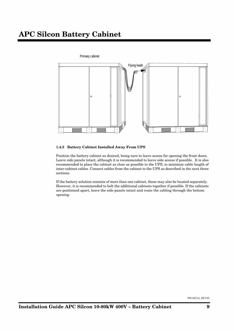
1.4.3 Battery Cabinet Installed Away From UPS
Position the battery cabinet as desired, being sure to leave access for opening the front doors. Leave side panels intact, although it is recommended to leave side access if possible. It is also recommended to place the cabinet as close as possible to the UPS, to minimize cable length of inter-cabinet cables. Connect cables from the cabinet to the UPS as described in the next three sections.
If the battery solution consists of more than one cabinet, these may also be located separately. However, it is recommended to bolt the additional cabinets together if possible. If the cabinets are positioned apart, leave the side panels intact and route the cabling through the bottom opening.
Primary cabinet
Flying leads

10 Installation Guide APC Silcon 10-80kW 400V – Battery Cabinet
990-4023A_REV02
APC Silcon Battery Cabinet
1.5 Terminals
V002
V001
X009
X010
X011
Battery cabinet terminal locations
X012
X003
X004
DANGER: Hazardous voltage.Risk of electric shock. Do not touchuninsulated battery terminal.
ATTENTION: Tension dangereuse.Risque de choc électrique. Ne pastoucher les cosses des batteries. 885-4367
Earth stud. More information in section 1.6.1.
APC Silcon Battery Cabinet
990-4023A_REV02
Installation Guide APC Silcon 10-80kW 400V – Battery Cabinet 11
1.6 Before Starting Up
1.6.1 Connecting the APC Silcon UPS and the APC Silcon Battery Cabinet
Please refer to the APC Silcon Installation Guide for cable dimensions.
The following procedure is recommended for connection of batteries:
1. Connect the UPS terminals X004 and X012 on the System Integration Interface-board to the terminals X009, X010 and X012 in the battery cabinet by means of the wires marked 150 to 158. These wires must be separated from the power cables. Refer to Example Diagram below.
2. If using a shunt trip (Emergency Power Off) connect wiring to terminal X011 in the battery cabinet. Refer to Example Diagram on page 12.
3. Connect the UPS terminals PE, X003, and X004 to the corresponding terminals in the battery cabinet. Refer to Example Diagram on page 12, and photo on page 10.
4. Mount top and front covers; connect earth conductor.
5. Verify the circuit breakers are in the „OFF" position.
6. Unfasten safety bolts for top shelf.
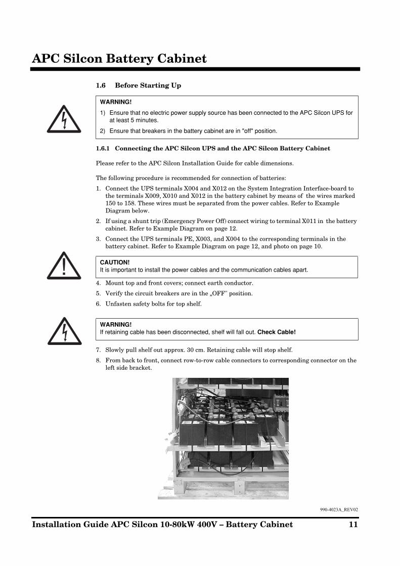
7. Slowly pull shelf out approx. 30 cm. Retaining cable will stop shelf.
8. From back to front, connect row-to-row cable connectors to corresponding connector on the left side bracket.
WARNING!
1) Ensure that no electric power supply source has been connected to the APC Silcon UPS for at least 5 minutes.
2) Ensure that breakers in the battery cabinet are in "off" position.
CAUTION!
It is important to install the power cables and the communication cables apart.
WARNING!
If retaining cable has been disconnected, shelf will fall out.
Check Cable!

12 Installation Guide APC Silcon 10-80kW 400V – Battery Cabinet
990-4023A_REV02
APC Silcon Battery Cabinet
9. Secure remaining shelf-to-shelf connector, to avoid accidental contact.
10. Push shelf back in and secure with safety bolts.
11. Repeat for second and third shelf (on second shelf, connect corresponding colors together. Refer to scematic).
12. Connect the shelf to shelf connectors.
13. Verify correct voltage at input side of circuit breakers.
14. Operate battery cabinet and circuit breakers per UPS instructions.
15. It is recommended that a battery capacity test is performed after the installation is completed
Example Diagram
WARNING!
1. Follow the UPS start-up procedure described in the APC Silcon Installation Guide.
2. To avoid damaging the system do not close battery breaker until display shows:
INSERT FUSE OR CLOSE MCB
NOTICE!
After starting up the system, check that the battery temperature can be displayed by pressing 5 & 8 simultaneously on the UPS display. If not correctly installed/configured the display will show: NV (Not Valid).

APC Silcon Battery Cabinet
990-4023A_REV02
Installation Guide APC Silcon 10-80kW 400V – Battery Cabinet 13
1.7 Parallel Connection (÷XRI and ÷XR2 cabinets)
Parallel connection of battery cabinets establishes the possibility of extending the back-up time.
Recommendation: Place the cabinet containing the battery breaker next to the UPS.
For extended runtime, additional battery cabinets can be added in parallel strings. (Product numbers SLB10K80HXR1 and SLB10K80HXR2). When installing parallel battery cabinets, the primary cabinet containing the circuit breakers should be either bolted to the UPS, or in close proximity. All other cabinets will not contain a circuit breaker. The maximum number of battery strings to be in parallel is four.
Sufficient cabling is provided, assuming all cabinets shall be bolted together. If cabinets are spaced apart, custom cables must be manually crimped.
At the top of the primary cabinet are two connectors: 1st string (yellow) and 2nd string (blue). Each connector contains a(+) and (-) line. With the inter-cabinet harness, connect the 1st string connectors (Yellow) from the primary cabinet to the XR cabinet. Use the connector at the right side of the XR cabinet. Repeat for the 2nd string (blue) connectors.
If connecting additional XR cabinets, simply continue to link the strings as above. Connectors at the left side of a cabinet connect to the same color connectors at the right side of the next cabinet.

14 Installation Guide APC Silcon 10-80kW 400V – Battery Cabinet
990-4023A_REV02
How to Contact APC
2.0 How to Contact APC
APC Corporate
132 Fairgrounds Road West Kingston, RI 02892USA
Tel.: +1 401 789-5735Fax: +1 401 789-3710
Pre-sales Technical Support+1 877-474-5266
Post-sales Technical Support+1 877-287-7835
APC Ireland, GalwayBallybrit Business ParkIreland
Tel.: + 353 917 02000Fax: + 353 917 56909
Pre-sales Technical Support + 353 91 70 26 10
Post-sales Technical Support + 353 91 75 52 75
Web: www.apc.com/support

Appendix
990-4023A_REV02
Installation Guide APC Silcon 10-80kW 400V – Battery Cabinet 15
3.0 Appendix
3.1 Appendix – SLB40K60H1 Battery Cabinet Cabling Diagram
X009
X010
X011
X012
X003
X004
V001
100A
F001 F002
100A
V002
12B
25A 24A 23A 22A 21A
20A 19A 18A 17A 16A
15A 14A 13A 12A 11A
10A 9A 8A 7A 6A
5A 4A 3A 2A 1A
11B 10B 9B
8B 7B 6B 5B
4B 3B 2B 1B
32A 31A 30A
28A 27A 26A
29A
32B 31B 30B 29B
28B 27B 26B 25B
24B 23B 22B 21B
20B 19B 18B 17B
16B 15B 14B 13B
Second string (blue)
Front of cabinet (first string) top shelf
First string (yellow)
Leftside pan of cabinet. (Cabinet to cabinet connectors).
Second string (three rear rows)
Front of cabinet (first string) middle shelf (two front rows)
Front of cabinet (second string) bottom shelf
To UPSfirst string
To UPSsecond string
(Control wiring) to UPS
(Power wiring) to UPS
E
Not
es1.
Pow
er w
iring
and
con
trol w
iring
sho
uld
be s
egre
gate
d.2.
To e
xten
d th
e ba
ckup
tim
e, b
atte
ry c
ubic
les
can
be p
aral
lele
d.3.
In
stal
latio
n m
ust c
ompl
y w
ith a
ll ap
plic
able
nat
iona
l and
loca
l cod
es.
Fuse100A
Fuse100A

16 Installation Guide APC Silcon 10-80kW 400V – Battery Cabinet
990-4023A_REV02
Appendix
3.2 Appendix – SLB40K60H1, Schematic
2
2 (1>) 2 (1>)
+ –
11 3
1 2 3 21 3 4 21 1 2
C16 514 4
–+ –+
311 C22 1
X010
X009
H002
H001
X011
X012
1
2
1
1
2
1
2
3
1
2
3
414
14
11
11
F002F001
F001100A
F002100A
100A100A
STST
C1
C1
C2
C2
X003 X004 E
X009 X010 X011 X012
PE
V001 V002
14 6 5 4
+ –
Fuse
Battery (First String) Battery (Second String)
Connection Point for Extended Run Cabinet
Battery(First String)
supply for UPS
Battery(Second String)supply for UPS
F001:Aux.A
F002:Aux.A
Temp. SensorBattery Cabinet
LED signal from UPS“OK for operating corresponding MCCB”
MCCB position signals for UPS
Trip for emergency stop (220-240V AC)
Battery temperature sensing for compensation of charging voltage
NOTE:ST: Shunt tripC1, C2: Shunt trip coil connections
Control Circuit
Power Circuit
Fuse

Appendix
990-4023A_REV02
Installation Guide APC Silcon 10-80kW 400V – Battery Cabinet 17
3.3 Appendix – SLB40K60H1, Electrical Configuration (dimension in mm)
773
143
1410
914
8001270
125125
914
1435
X009
X010
X011X012
X003 (+)
X003 (-)
X004 (+)
X004 (-)
Minimum coolingand service clearance
View ARight side view
Power Wiring
View A
Left side view of power connectors
– access cover removed.
Front view
Secondstring
First string
Cooling vents
Minimum service
clearance
Notes:
1. Battery Cabling voltage drop should not exceed 1%.
2. Circuit Breakers F001, F002 and fuses are 100 AMP.
3. Wiring configuration shown is for reference only.
4. Installation must comply with national and local codes.
First string
(yellow)
Secondstring(blue)
M8 Bolt
To UPSControl Wiring
To UPSPower Wiring
F002
F001
Second string
First string

18 Installation Guide APC Silcon 10-80kW 400V – Battery Cabinet
990-4023A_REV02
Appendix
3.4 Appendix – SLB40K60H2 Battery Cabinet, Cabling Diagram
25A 22A 21A23A24A
20A 17A 16A18A19A
15A 12A 11A13A14A
10A 7A 6A8A9A
5A 2A 1A3A4A
12B 9B10B11B
8B 5B6B7B
4B 1B2B3B
32A 29A30A31A
28A 26A27A
32B 29B30B31B
28B 25B26B27B
24B 21B22B23B
20B 17B18B19B
16B 13B14B15B
F002
V002V001
X009
X010
X011
X012
X003
X004
100A100A
F001
Notes:1. Power wiring and control wiring should be segregated.2. To extend the backup time, Battery cubicles can be paralleled.3. Installation must comply with all applicable national and local codes.
Second string (blue)
Front of cabinet (first string) top shelf
First string (yellow)
Leftside pan of cabinet. (Cabinet to cabinet connectors).
Second string (three rear rows)
Front of cabinet (first string) middle shelf (two front rows)
Front of cabinet (second string) bottom shelf
To UPSfirst string
To UPSsecond string
(Control wiring) to UPS
(Power wiring) to UPS
E
Fuse100A
Fuse100A

Appendix
990-4023A_REV02
Installation Guide APC Silcon 10-80kW 400V – Battery Cabinet 19
3.5 Appendix – SLB40K60H2 Battery Cabinet Electrical Schematic
2
2 (1>) 2 (1>)
+ –
11 3
1 2 3 21 3 4 21 1 2
C16 514 4
–+ –+
311 C22 1
X010
X009
H002
H001
X011
X012
1
2
1
1
2
1
2
3
1
2
3
414
14
11
11
F002F001
F001100A
F002100A
100A100A
STST
C1
C1
C2
C2
X003 X004 E
X009 X010 X011 X012
PE
V001 V002
14 6 5 4
+ –
Fuse
Battery (First String) Battery (Second String)
Connection Point for Extended Run Cabinet
Battery(First String)
supply for UPS
Battery(Second String)supply for UPS
F001:Aux.A
F002:Aux.A
Temp. SensorBattery Cabinet
LED signal from UPS “OK for operating corresponding MCCB”
MCCB position signals for UPS
Trip for emergency stop (220-240V AC)
Battery temperature sensing for compensation of charging voltage
NOTE:ST: Shunt tripC1, C2: Shunt trip coil connections
Control Circuit
Power Circuit
Fuse
20 Installation Guide APC Silcon 10-80kW 400V – Battery Cabinet
990-4023A_REV02
Appendix
3.6 Appendix – SLB40K60H2 Battery Cabinet Electrical (dimensions in mm)
773
143
1410
914
8001270
125125
914
1435
X009
X010
X011X012
X003 (+)
X003 (-)
X004 (+)
X004 (-)
View A
Minimum coolingand service clearance
First string
View ARight side view
Power Wiring
Left side view of power connectors –
access cover removed.
Front view
Secondstring
First string
Cooling vents
Minimum service
clearance
Notes:
1. Battery Cabling voltage drop should not exceed 1%.
2. Circuit Breakers F001, F002 and fuses are 100 AMP.
3. Wiring configuration shown is for reference only.
4. Installation must comply with national and local codes.
First string
(yellow)
Secondstring(blue)
M8 Bolt
To UPSControl Wiring
To UPSPower Wiring
F002
F001
Second string
Top View

Appendix
990-4023A_REV02
Installation Guide APC Silcon 10-80kW 400V – Battery Cabinet 21
3.7 Appendix - SLB10K80HXR1 Battery Cabinet Cabling Diagram
25A
12B 11B 10B 9B
8B 7B 6B 5B
4B 3B 2B 1B
32A 31A 30A 29A
32B 31B 30B 29B
28B 27B 26B 25B
24B 23B 22B 21B
20B 19B 18B 17B
16B 15B 14B 13B
28A 27A 26A
22A 21A
20A 19A 18A 17A 16A
15A 14A 13A 12A 11A
10A 9A 8A 7A 6A
5A 4A 3A 2A 1A
23A24A
This end should be connected to the first string connector in the main cabinet SLB40K60H1SLB80KH1
This end should be connected to the second string connector in the main cabinetSLB40K60H1SLB80KH1
First string(yellow)
Second string (blue)
Front of cabinet (first string) top shelf
First string (yellow)
Leftside pan of cabinet. (Cabinet to cabinet connectors).
Fuse
Second string (three rear rows)
Front of cabinet (first string) middle shelf (two front rows)
Front of cabinet (second string) bottom shelf
Fuse
E
Second string(blue)
Notes:
1. Power wiring and control wiring should be segregated
2. Fuse ratings are 100A when used with SLB40K60H1
3. Fuse ratings are 125A when used with SLB80KH1
4. Installation must comply with all applicable national and local codes

22 Installation Guide APC Silcon 10-80kW 400V – Battery Cabinet
990-4023A_REV02
Appendix
3.8 Appendix – SLB10K80HXR2, Electrical Configuration (dimensions in mm)
1270
123
1410
914
1435
914
773
800
View B
Minimum coolingand service clearance
View BRight side view
First string
(yellow)
Second string(blue)
Top view
Left side view of power connectors
– access cover removed.
Front view
Secondstring
First string
Cooling ventsFirst string
Second string
Minimum service clearance
Notes:
1. Battery Cabling voltage drop should not exceed 1%.
2. Fuse Ratings are 100 AMP when using this with SLB40K60H1.
3. Fuse ratings are 125 AMP when using this with SLB80KH1.
4. Wiring configuration shown is for reference only.
5. Installation must comply with national and local codes.
First string
(yellow)
Secondstring(blue)
Powerconnectors
First string
Second string

Appendix
990-4023A_REV02
Installation Guide APC Silcon 10-80kW 400V – Battery Cabinet 23
3.9 Appendix – SLB10K80HXR2 Battery Cabinet Cabling Diagram
25A
12B 11B 10B 9B
8B 7B 6B 5B
4B 3B 2B 1B
32A 31A 30A 29A
32B 31B 30B 29B
28B 27B 26B 25B
24B 23B 22B 21B
20B 19B 18B 17B
16B 15B 14B 13B
28A 27A 26A
22A 21A
20A 19A 18A 17A 16A
15A 14A 13A 12A 11A
10A 9A 8A 7A 6A
5A 4A 3A 2A 1A
23A24A
This end should be connected to the first string connector in the main cabinet SLB40K60H2 andSLB80KH2
This end should be connected to the second string connector in the main cabinet SLB40K60H2 andSLB80KH2
First string(yellow)
Secondstring (blue)
Front of cabinet (first string) top shelf
First string (yellow)
Leftside pan of cabinet. (Cabinet to cabinet connectors).
Fuse
Second string (three rear rows)
Front of cabinet (first string) middle shelf (two front rows)
Front of cabinet (second string) bottom shelf
Fuse
E
Second string(blue)
Notes:
1. Power wiring and control wiring should be segregated
2. Fuse ratings are 100A when used with SLB40K60H2
3. Fuse ratings are 125A when used with SLB80KH2
4. Installation must comply with all applicable national and local codes

24 Installation Guide APC Silcon 10-80kW 400V – Battery Cabinet
990-4023A_REV02
Appendix
3.10 Appendix – SLB10K80HXR1, Electrical Configuration (dimensions in mm)
1270
123
1410
914
1435
914
773
800
View B
Minimum coolingand service clearance
A
View BRight side view
First string(yellow)
Second string(blue)
Top view
Left side view of power connectors
– access cover removed.
Front view
Secondstring
First string
Cooling vents First string
Second string
Minimum service clearance
Notes:
1. Battery Cabling voltage drop should not exceed 1%.
2. Fuse Ratings are 100 AMP when using this with SLB40K60H2.
3. Fuse ratings are 125 AMP when using this with SLB80KH2.
4. Wiring configuration shown is for reference only.
5. Installation must comply with national and local codes.
First string
(yellow)
Secondstring(blue)
Powerconnectors

Appendix
990-4023A_REV02
Installation Guide APC Silcon 10-80kW 400V – Battery Cabinet 25
3.11 Appendix – SLB40K60H1+HXR1 Battery Cabinet, Cabling Diagram
12B
11B
10B
9B
8B7B
6B5B
4B3B
2B1B
25A
24A
23A
22A
21A
20A
19A
18A
17A
16A
15A
14A
13A
12A
11A
10A
9A8A
7A6A
5A4A
3A2A
1A
25A
24A
23A
22A
21A
20A
19A
18A
17A
16A
15A
14A
13A
12A
11A
10A
9A8A
7A6A
5A4A
3A2A
1A
32A
31A
X009
X010
X011
X012
X003
X004
V001
100A
F002
F001
100A
V002
30A
29A
32B
31B
30B
29B
28B
27B
26B
25B
24B
23B
22B
21B
20B
19B
18B
17B
16B
15B
14B
13B
32B
31B
30B
29B
28B
27B
26B
25B
24B
23B
22B
21B
20B
19B
18B
17B
16B
15B
14B
13B
28A
27A
26A
12B
11B
10B
9B
8B7B
6B5B
4B3B
2B1B
32A
31A
30A
29A
28A
27A
26A
Not
es1.
Pow
er w
iring
and
con
trol w
iring
sho
uld
be s
egre
gate
d.2.
To
exte
nd th
e ba
ckup
tim
e, b
atte
ry c
ubic
les
can
be p
aral
lele
d.3.
Inst
alla
tion
mus
t com
ply
with
all
appl
icab
le n
atio
nal a
nd lo
cal c
odes
.
Fron
t of c
abin
et (s
econ
d st
ring)
bot
tom
she
lfFr
ont o
f cab
inet
(sec
ond
strin
g) b
otto
m s
helf
Fron
t of c
abin
et (f
irst s
tring
) mid
dle
shel
f(tw
o fro
nt ro
ws
Seco
nd s
tring
(Thr
ee re
ar ro
ws)
Seco
nd s
tring
(Thr
ee re
ar ro
ws)
Fron
t of C
abin
et (f
irst s
tring
) top
she
lfFr
ont o
f Cab
inet
(firs
t stri
ng) t
op s
helf
Firs
t stri
ng (y
ello
w)
Left
side
pan
of c
abin
et. (
Cab
inet
to c
abin
et c
onne
ctor
s).
Seco
nd s
tring
(b
lue)
Firs
t stri
ng (y
ello
w)
Left
side
pan
of c
abin
et. (
Cab
inet
to c
abin
et c
onne
ctor
s).
XR C
abin
etM
ain
Cab
inet
Fuse
100A
Fuse
100A
Fuse
100A
Fuse
100A
To U
PSfir
st
strin
g
To U
PSse
cond
st
ring
(Con
trol w
iring
) to
UPS
(Pow
er w
iring
) to
UPS PE
PE
Fron
t of c
abin
et (f
irst s
tring
) mid
dle
shel
f(tw
o fro
nt ro
ws
Seco
nd s
tring
(b
lue)
Firs
t stri
ng (y
ello
w)
Seco
nd s
tring
(b
lue)

26 Installation Guide APC Silcon 10-80kW 400V – Battery Cabinet
990-4023A_REV02
Appendix
3.12 Appendix – SLB40K60H1+HXR1 Battery Cabinet Electrical Schematic
C2211 3 1
+ – + – 1
C1
2 3 21 3 4 21 1 2
C1
C2
X010
X009
H002
H001
X011
X012
1
2
1
2
1
2
3
1
2
3
414
14
11
11
F002F001STST
C1
C2
14 6 5 4
211 3 1
14 6 5 4
2 (l >) 2 (l >)
F001100A
F002100A
X003 X004
X009 X010 X011 X012
V001 V002
PEE
Battery (First String) XR Cabinet Battery (Second String) XR Cabinet
Connection Point for further Extended Run Cabinet
Battery(First String)
supply for UPS
Battery(Second String)supply for UPS
F001:Aux.A
F002:Aux.A
Temp. SensorBattery Cabinet
LED signal from UPS“OK for operating corresponding MCCB”
MCCB positionsignals for UPS
Trip for emergency stop(220-240V AC)
Battery temperature sensing for compensation of charging voltageNOTE:
ST: Shunt tripC1, C2: Shunt trip coil connections
Control Circuit
Power Circuit
Main Cabinet Main Cabinet
Fuse100A
Fuse100A
Fuse100A
Fuse100A

Appendix
990-4023A_REV02
Installation Guide APC Silcon 10-80kW 400V – Battery Cabinet 27
3.13 Appendix – SLB40K60H1+HXR1 Battery Cabinet Electrical (dimensions in mm)
773
12701270
143
125
800
1410
F001
F002
914
125
914
1435
X009
X010
X011X012
X003 (+)
X003 (–)
X004 (+)
X004 (–)
Firststring(typ.)
Secondstring(blue)
Firststring
(yellow)
Power connectors
(cover removed)
Secondstring(typ.)
View A
To UPSControl Wiring
To UPSPower Wiring
View ARight side view
Minimum coolingand service clearance
Minimum ServiceClearance
Front View Front View
Top Views
Cooling vents Cooling ventsFirststring(typ.
Secondstring(typ.)
View A
Notes:1. Battery cabling voltage
drop should not exceed 1%.
2. Circuit breakers F001, F002 and fuses are 100AMP
3. Wiring configuration shown is for reference only.
4. Installation must comply with national and local codes.

28 Installation Guide APC Silcon 10-80kW 400V – Battery Cabinet
990-4023A_REV02
Appendix
3.14 Appendix – SLB40K60H2+HXR2 Battery Cabinet, Cabling Diagram
12B
11B
10B
9B
8B7B
6B5B
4B3B
2B1B
25A
24A
23A
22A
21A
20A
19A
18A
17A
16A
15A
14A
13A
12A
11A
10A
9A8A
7A6A
5A4A
3A2A
1A
25A
24A
23A
22A
21A
20A
19A
18A
17A
16A
15A
14A
13A
12A
11A
10A
9A8A
7A6A
5A4A
3A2A
1A
32A
31A
X009
X010
X011
X012
X003
X004
V001
100A
F002
F001
100A
V002
30A
29A
32B
31B
30B
29B
28B
27B
26B
25B
24B
23B
22B
21B
20B
19B
18B
17B
16B
15B
14B
13B
32B
31B
30B
29B
28B
27B
26B
25B
24B
23B
22B
21B
20B
19B
18B
17B
16B
15B
14B
13B
28A
27A
26A
12B
11B
10B
9B
8B7B
6B5B
4B3B
2B1B
32A
31A
30A
29A
28A
27A
26A
Not
es1.
Pow
er w
iring
and
con
trol w
iring
sho
uld
be s
egre
gate
d.2.
To
exte
nd th
e ba
ckup
tim
e, b
atte
ry c
ubic
les
can
be p
aral
lele
d.3.
Inst
alla
tion
mus
t com
ply
with
all
appl
icab
le n
atio
nal a
nd lo
cal c
odes
.
Fron
t of c
abin
et (s
econ
d st
ring)
bot
tom
she
lfFr
ont o
f cab
inet
(sec
ond
strin
g) b
otto
m s
helf
Fron
t of c
abin
et (f
irst s
tring
) mid
dle
shel
f(tw
o fro
nt ro
ws
Seco
nd s
tring
(Thr
ee re
ar ro
ws)
Seco
nd s
tring
(Thr
ee re
ar ro
ws)
Fron
t of C
abin
et (f
irst s
tring
) top
she
lfFr
ont o
f Cab
inet
(firs
t stri
ng) t
op s
helf
Firs
t stri
ng (y
ello
w)
Left
side
pan
of c
abin
et. (
Cab
inet
to c
abin
et c
onne
ctor
s).
Seco
nd s
tring
(b
lue)
Firs
t stri
ng (y
ello
w)
Left
side
pan
of c
abin
et. (
Cab
inet
to c
abin
et c
onne
ctor
s).
XR C
abin
etM
ain
Cab
inet
Fuse
100A
Fuse
100A
Fuse
100A
Fuse
100A
To U
PSfir
st
strin
g
To U
PSse
cond
st
ring
(Con
trol w
iring
) to
UPS
(Pow
er w
iring
) to
UPS E
E
Fron
t of c
abin
et (f
irst s
tring
) mid
dle
shel
f(tw
o fro
nt ro
ws
Seco
nd s
tring
(b
lue)
Seco
nd s
tring
(b
lue)
Firs
t stri
ng (y
ello
w)

Appendix
990-4023A_REV02
Installation Guide APC Silcon 10-80kW 400V – Battery Cabinet 29
3.15 Appendix – SLB40K60H2+HXR2 Battery Cabinet, Electrical Schematic
C2211 3 1
+ – + – 1
C1
2 3 21 3 4 21 1 2
C1
C2
X010
X009
H002
H001
X011
X012
1
2
1
2
1
2
3
1
2
3
414
14
11
11
F002F001STST
C1
C2
14 6 5 4
211 3 1
14 6 5 4
2 (l >) 2 (l >)
F001100A
F002100A
X003 X004
X009 X010 X011 X012
V001 V002
PEE
Battery (First String) XR Cabinet Battery (Second String) XR Cabinet
Connection Point for further Extended Run Cabinet
Battery(First String)
supply for UPS
Battery(Second String)supply for UPS
F001:Aux.A
F002:Aux.A
Temp. SensorBattery Cabinet
LED signal from UPS“OK for operating corresponding MCCB”
MCCB positionsignals for UPS
Trip for emergency stop220-240V AC)
Battery temperature sensing for compensation of charging voltage
NOTE:ST: Shunt tripC1, C2: Shunt trip coil connections
Control Circuit
Power Circuit
Main Cabinet Main Cabinet
Fuse100A
Fuse100A
Fuse100A
Fuse100A

30 Installation Guide APC Silcon 10-80kW 400V – Battery Cabinet
990-4023A_REV02
Appendix
3.16 Appendix – SLB40K60H2+HXR2 Battery Cabinet, Electrical, (dimensions in mm)
773
12701270
143
125
800
1410
F001
F002
914
125
914
1435
X009
X010
X011X012
X003 (+)
X003 (–)
X004 (+)
X004 (–)
Firststring(typ.)
Secondstring(blue)
Firststring
(yellow)
Power connectors
(cover removed)
Secondstring(typ.)
View A
To UPSControl Wiring
To UPSPower Wiring
View ARight side view
Minimum coolingand service clearance
Minimum ServiceClearance
Front View Front View
Top Views
Cooling vents Cooling ventsFirststring(typ.)
Secondstring(typ.)
View A
Notes:1. Battery cabling voltage
drop should not exceed 1%.
2. Circuit breakers F001, F002 and fuses are 100AMP
3. Wiring configuration shown is for reference only.
4. Installation must comply with national and local codes.
-

Appendix
990-4023A_REV02
Installation Guide APC Silcon 10-80kW 400V – Battery Cabinet 31
3.17 Appendix – SLB80KH1 Battery Cabinet, Cabling Diagram
X009
X010
X011
X012
X003
X004
V001
125A
F001 F002
125A
V002
12B
25A 24A 23A 22A 21A
20A 19A 18A 17A 16A
15A 14A 13A 12A 11A
10A 9A 8A 7A 6A
5A 4A 3A 2A 1A
11B 10B 9B
8B 7B 6B 5B
4B 3B 2B 1B
32A 31A 30A
28A 27A 26A
29A
32B 31B 30B 29B
28B 27B 26B 25B
24B 23B 22B 21B
20B 19B 18B 17B
16B 15B 14B 13B
Second string (blue)
Front of cabinet (first string) top shelf
First string (yellow)
Leftside pan of cabinet. (Cabinet to cabinet connectors).
Second string (three rear rows)
Front of cabinet (first string) middle shelf (two front rows)
Front of cabinet (second string) bottom shelf
To UPSfirst string
To UPSsecond string
(Control wiring) to UPS
(Power wiring) to UPS
E Not
es1.
Pow
er w
iring
and
con
trol w
iring
sho
uld
be s
egre
gate
d.2.
To
exte
nd th
e ba
ckup
tim
e, b
atte
ry c
ubic
les
can
be p
aral
lele
d.3.
Inst
alla
tion
mus
t com
ply
with
all
appl
icab
le n
atio
nal a
nd lo
cal c
odes
.
Fuse125A
Fuse125A

32 Installation Guide APC Silcon 10-80kW 400V – Battery Cabinet
990-4023A_REV02
Appendix
3.18 Appendix – SLB80KH1 Battery Cabinet, Electrical Schematic
2
2 (1>) 2 (1>)
11 3
1 2 3 21 3 4 21 1 2
C16 514 4
–+ –+
311 C22 1
X010
X009
H002
H001
X011
X012
1
2
1
1
2
1
2
3
1
2
3
414
14
11
11
F002F001
F001125A
F002125A
STST
C1
C1
C2
C2
X003 X004 E
X009 X010 X011 X012
PE
V001 V002
14 6 5 4
Battery (First String) Battery (Second String)
Connection Point for Extended Run Cabinet
Battery(First String)
supply for UPS
Battery(Second String)supply for UPS
F001:Aux.A
F002:Aux.A
Temp. SensorBattery Cabinet
LED signal from UPS“OK for operating corresponding MCCB”
MCCB positionsignals for UPS
Trip for emergency stop(220-240V AC)
Battery temperature sensing for compensation of charging voltage
NOTE:ST: Shunt tripC1, C2: Shunt trip coil connections
Control Circuit
Power Circuit
Fuse125A
Fuse125A

Appendix
990-4023A_REV02
Installation Guide APC Silcon 10-80kW 400V – Battery Cabinet 33
3.19 Appendix – SLB80KH1 Battery Cabinet, Electrical (dimensions in mm)
773
143
1410
914
8001270
125125
914
1435
X009
X010
X011X012
X003 (+)
X003 (-)
X004 (+)
X004 (-)
Minimum coolingand service clearance
First string
View A Right side view
Power Wiring
View A
Left side view of power connectors – access
cover removed.
Front view
Secondstring
First string Cooling vents
Minimum service
clearance
Notes:
1. Battery Cabling voltage drop should not exceed 1%.
2. Circuit Breakers F001, F002 and fuses are 125 AMP.
3. Wiring configuration shown is for reference only.
4. Installation must comply with national and local codes.
First string
(yellow)
Secondstring(blue)
M8 Bolt
To UPSControl Wiring
To UPSPower Wiring
F002
F001
Second string
34 Installation Guide APC Silcon 10-80kW 400V – Battery Cabinet
990-4023A_REV02
Appendix
3.20 Appendix – SLB80KH2 Battery Cabinet, Cabling Diagram
X009
X010
X011
X012
X003
X004
V001
125A
F001 F002
125A
V002
12B
25A 24A 23A 22A 21A
20A 19A 18A 17A 16A
15A 14A 13A 12A 11A
10A 9A 8A 7A 6A
5A 4A 3A 2A 1A
11B 10B 9B
8B 7B 6B 5B
4B 3B 2B 1B
32A 31A 30A
28A 27A 26A
29A
32B 31B 30B 29B
28B 27B 26B 25B
24B 23B 22B 21B
20B 19B 18B 17B
16B 15B 14B 13B
Second string (blue)
Front of cabinet (first string) top shelf
First string (yellow)
Leftside pan of cabinet. (Cabinet to cabinet connectors).
Second string (three rear rows)
Front of cabinet (first string) middle shelf (two front rows)
Front of cabinet (second string) bottom shelf
To UPSfirst string
To UPSsecond string
(Control wiring) to UPS
(Power wiring) to UPS
E Not
es1.
Pow
er w
iring
and
con
trol w
iring
sho
uld
be s
egre
gate
d.2.
To
exte
nd th
e ba
ckup
tim
e, b
atte
ry c
ubic
les
can
be p
aral
lele
d.3.
Inst
alla
tion
mus
t com
ply
with
all
appl
icab
le n
atio
nal a
nd lo
cal c
odes
.
Fuse125A
Fuse125A

Appendix
990-4023A_REV02
Installation Guide APC Silcon 10-80kW 400V – Battery Cabinet 35
3.21 Appendix – SLB80KH2 Battery Cabinet, Electrical Schematic
2
2 (1>) 2 (1>)
11 3
1 2 3 21 3 4 21 1 2
C16 514 4
–+ –+
311 C22 1
X010
X009
H002
H001
X011
X012
1
2
1
1
2
1
2
3
1
2
3
414
14
11
11
F002F001
F001125A
F002125A
STST
C1
C1
C2
C2
X003 X004 E
X009 X010 X011 X012
PE
V001 V002
14 6 5 4
Battery (First String) Battery (Second String)
Connection Point for Extended Run Cabinet
Battery(First String)
supply for UPS
Battery(Second String)supply for UPS
F001:Aux.A
F002:Aux.A
Temp. SensorBattery Cabinet
LED signal from UPS“OK for operating corresponding MCCB”
MCCB positionsignals for UPS
Trip for emergency stop(220-240V AC)
Battery temperature sensing for compensation of charging voltage
NOTE:ST : Shunt tripC1, C2 : Shunt trip coil connections
Control Circuit
Power Circuit
Fuse125A
Fuse125A
Main Cabinet Maine Cabinet

36 Installation Guide APC Silcon 10-80kW 400V – Battery Cabinet
990-4023A_REV02
Appendix
3.22 Appendix – SLB80KH2 Battery Cabinet, Electrical (dimensions in mm)
773
143
1410
914
8001270
125125
914
1435
X009
X010
X011X012
X003 (+)
X003 (-)
X004 (+)
X004 (-)
View A
Minimum coolingand service clearance
First string
View ARight side view
Power Wiring
Left side view of power connectors –
access cover removed.
Front view
Second string
First stringCooling vents
Minimum service
clearance
Notes:
1. Battery Cabling voltage drop should not exceed 1%.
2. Circuit Breakers F001, F002 and fuses are 125 AMP.
3. Wiring configuration shown is for reference only.
4. Installation must comply with national and local codes.
First string
(yellow)
Secondstring(blue)
M8 Bolt
To UPSControl Wiring
To UPSPower Wiring
F002
F001
Second string

Appendix
990-4023A_REV02
Installation Guide APC Silcon 10-80kW 400V – Battery Cabinet 37
3.23 Appendix – SLB80KH1+HXR1 Battery Cabinet, Cabling Diagram
12B
11B
10B
9B
8B7B
6B5B
4B3B
2B1B
25A
24A
23A
22A
21A
20A
19A
18A
17A
16A
15A
14A
13A
12A
11A
10A
9A8A
7A6A
5A4A
3A2A
1A
25A
24A
23A
22A
21A
20A
19A
18A
17A
16A
15A
14A
13A
12A
11A
10A
9A8A
7A6A
5A4A
3A2A
1A
32A
31A
X009
X010
X011
X012
X003
X004
V001
125A
F002
F001
125A
V002
30A
29A
32B
31B
30B
29B
28B
27B
26B
25B
24B
23B
22B
21B
20B
19B
18B
17B
16B
15B
14B
13B
32B
31B
30B
29B
28B
27B
26B
25B
24B
23B
22B
21B
20B
19B
18B
17B
16B
15B
14B
13B
28A
27A
26A
12B
11B
10B
9B
8B7B
6B5B
4B3B
2B1B
32A
31A
30A
29A
28A
27A
26A
Not
es1.
Pow
er w
iring
and
con
trol w
iring
sho
uld
be s
egre
gate
d.2.
To
exte
nd th
e ba
ckup
tim
e, b
atte
ry c
ubic
les
can
be p
aral
lele
d.3.
Inst
alla
tion
mus
t com
ply
with
all
appl
icab
le n
atio
nal a
nd lo
cal c
odes
.
Fron
t of c
abin
et (s
econ
d st
ring)
bot
tom
she
lfFr
ont o
f cab
inet
(sec
ond
strin
g) b
otto
m s
helf
Fron
t of c
abin
et (f
irst s
tring
) mid
dle
shel
f(tw
o fro
nt ro
ws
Seco
nd s
tring
(Thr
ee re
ar ro
ws)
Seco
nd s
tring
(Thr
ee re
ar ro
ws)
Fron
t of C
abin
et (f
irst s
tring
) top
she
lfFr
ont o
f Cab
inet
(firs
t stri
ng) t
op s
helf
Firs
t stri
ng
(yel
low
)
Left
side
pan
of c
abin
et. (
Cab
inet
to c
abin
et c
onne
ctor
s).
Seco
nd s
tring
(b
lue)
Firs
t stri
ng (y
ello
w)
Left
side
pan
of c
abin
et. (
Cab
inet
to c
abin
et c
onne
ctor
s).
XR C
abin
etM
ain
Cab
inet
Fuse
125A
Fuse
125A
Fuse
125A
Fuse
125A
To U
PSfir
st
strin
g
To U
PSse
cond
stri
ng
(Con
trol w
iring
) to
UPS
(Pow
er w
iring
) to
UPS E
E
Fron
t of c
abin
et (f
irst s
tring
) mid
dle
shel
f(tw
o fro
nt ro
ws
Seco
nd s
tring
(b
lue)
Seco
nd s
tring
(b
lue)
Firs
t stri
ng
(yel
low
)

38 Installation Guide APC Silcon 10-80kW 400V – Battery Cabinet
990-4023A_REV02
Appendix
3.24 Appendix – SLB80KH1+HXR1 Battery Cabinet, Electrical Schematic
C2211 3 1
+ – 1
C1
2 3 21 3 4 21 1 2
C1
–+
C2
X010
X009
H002
H001
X011
X012
1
2
1
2
1
2
3
1
2
3
414
14
11
11
F002F001STST
C1
C2
14 6 5 4
211 3 1
14 6 5 4
2 (l >) 2 (l >)
F001125A
F002125A
X003 X004
X009 X010 X011 X012
V001 V002
PEE
Battery (First String) XR Cabinet Battery (Second String) XR Cabinet
Connection Point for further Extended Run Cabinet
Battery(First String)
supply for UPS
Battery(Second String)supply for UPS
F001:Aux.A
F002:Aux.A
Temp. SensorBattery Cabinet
LED signal from UPS“OK for operating corresponding MCCB”
MCCB positionsignals for UPS
Trip for emergency stop(220-240V AC)
Battery temperature sensing for compensation of charging voltage
NOTE:ST : Shunt tripC1, C2 : Shunt trip coil connections
Control Circuit
Power Circuit
Fuse125A
Fuse125A
Fuse125A
Fuse125A
Main CabinetMain Cabinet

Appendix
990-4023A_REV02
Installation Guide APC Silcon 10-80kW 400V – Battery Cabinet 39
3.25 Appendix – SLB80KH1+HXR1 Battery Cabinet Electrical (dimensions in mm)
773
12701270
143
125
800
1410
F001
F002
914
125
914
1435
X009
X010
X011X012
X003 (+)
X003 (–)
X004 (+)
X004 (–)
Firststring(typ.)
Secondstring(blue)
Firststring
(yellow)
Power connectors
(cover removed)
Secondstring(typ.)
View A
To UPSControl Wiring
To UPSPower Wiring
View ARight side view
Minimum coolingand service clearance
Minimum ServiceClearance
Front View Front View
Top Views
Cooling vents Cooling vents
Firststring(typ.)
Secondstring(typ.)
View A
Not
es1.
Bat
tery
cab
ling
volta
ge d
rop
shou
ld n
ot e
xcee
d 1%
.2.
Circ
uit b
reak
ers
F00
1, F
002
and
fuse
s ar
e 12
5AM
P3.
Wiri
ng c
onfig
urat
ion
show
n is
for r
efer
ence
onl
y.4.
Inst
alla
tion
mus
t com
ply
with
nat
iona
l and
loca
l cod
es.

40 Installation Guide APC Silcon 10-80kW 400V – Battery Cabinet
990-4023A_REV02
Appendix
3.26 Appendix – SLB80KH2+HXR2 Battery Cabinet, Cabling Diagram
12B
11B
10B
9B
8B7B
6B5B
4B3B
2B1B
25A
24A
23A
22A
21A
20A
19A
18A
17A
16A
15A
14A
13A
12A
11A
10A
9A8A
7A6A
5A4A
3A2A
1A
25A
24A
23A
22A
21A
20A
19A
18A
17A
16A
15A
14A
13A
12A
11A
10A
9A8A
7A6A
5A4A
3A2A
1A
32A
31A
X009
X010
X011
X012
X003
X004
V001
125A
F002
F001
125A
V002
30A
29A
32B
31B
30B
29B
28B
27B
26B
25B
24B
23B
22B
21B
20B
19B
18B
17B
16B
15B
14B
13B
32B
31B
30B
29B
28B
27B
26B
25B
24B
23B
22B
21B
20B
19B
18B
17B
16B
15B
14B
13B
28A
27A
26A
12B
11B
10B
9B
8B7B
6B5B
4B3B
2B1B
32A
31A
30A
29A
28A
27A
26A
Not
es1.
Pow
er w
iring
and
con
trol w
iring
sho
uld
be s
egre
gate
d.2.
To
exte
nd th
e ba
ckup
tim
e, b
atte
ry c
ubic
les
can
be p
aral
lele
d.3.
Inst
alla
tion
mus
t com
ply
with
all
appl
icab
le n
atio
nal a
nd lo
cal c
odes
.
Fron
t of c
abin
et (s
econ
d st
ring)
bot
tom
she
lfFr
ont o
f cab
inet
(sec
ond
strin
g) b
otto
m s
helf
Fron
t of c
abin
et (f
irst s
tring
) mid
dle
shel
f(tw
o fro
nt ro
ws
Seco
nd s
tring
(Thr
ee re
ar ro
ws)
Seco
nd s
tring
(Thr
ee re
ar ro
ws)
Fron
t of C
abin
et (f
irst s
tring
) top
she
lfFr
ont o
f Cab
inet
(firs
t stri
ng) t
op s
helf
Firs
t stri
ng
(yel
low
)
Left
side
pan
of c
abin
et. (
Cab
inet
to c
abin
et c
onne
ctor
s).
Seco
nd s
tring
(b
lue)
Firs
t stri
ng (y
ello
w)
Left
side
pan
of c
abin
et. (
Cab
inet
to c
abin
et c
onne
ctor
s).
XR C
abin
etM
ain
Cab
inet
Fuse
125A
Fuse
125A
Fuse
125A
Fuse
125A
To U
PSfir
st
strin
g
To U
PSse
cond
st
ring
(Con
trol w
iring
) to
UPS
(Pow
er w
iring
) to
UPS E
E
Fron
t of c
abin
et (f
irst s
tring
) mid
dle
shel
f(tw
o fro
nt ro
ws
Seco
nd s
tring
(b
lue)
Seco
nd s
tring
(b
lue)
Firs
t stri
ng
(yel
low
)

Appendix
990-4023A_REV02
Installation Guide APC Silcon 10-80kW 400V – Battery Cabinet 41
3.27 Appendix – SLB80KH2+HXR2 Battery Cabinet, Electrical Schematic
C2211 3 1
+ – 1
C1
2 3 21 3 4 21 1 2
C1
–+
C2
X010
X009
H002
H001
X011
X012
1
2
1
2
1
2
3
1
2
3
414
14
11
11
F002F001STST
C1
C2
14 6 5 4
211 3 1
14 6 5 4
2 (l >) 2 (l >)
F001125A
F002125A
X003 X004
X009 X010 X011 X012
V001 V002
PEE
Battery (First String) XR Cabinet Battery (Second String) XR Cabinet
Connection Point for further Extended Run Cabinet
Battery(First String)
supply for UPS
Battery(Second String)supply for UPS
F001:Aux.A
F002:Aux.A
Temp. SensorBattery Cabinet
LED signal from UPS“OK for operating corresponding MCCB”
MCCB positionsignals for UPS
Trip for emergency stop(220-240V AC)
Battery temperature sensing for compensation of charging voltage
NOTE:ST : Shunt tripC1, C2 : Shunt trip coil connections
Control Circuit
Power Circuit
Fuse125A
Fuse125A
Fuse125A
Fuse125A
Main CabinetMain Cabinet

42 Installation Guide APC Silcon 10-80kW 400V – Battery Cabinet
990-4023A_REV02
Appendix
3.28 Appendix – SLB80KH2+HXR2 Battery Cabinet Electrical (dimensions in mm)
773
12701270
143
125
800
1410
F001
F002
914
125
914
1435
X009
X010
X011X012
X003 (+)
X003 (–)
X004 (+)
X004 (–)
Firststring(typ.)
Secondstring(blue)
Firststring
(yellow)
Power connectors
(cover removed)
Secondstring(typ.)
View A
To UPSControl Wiring
To UPSPower Wiring
View ARight side view
Minimum coolingand service clearance
Minimum ServiceClearance
Front View Front View
Top Views
Cooling vents Cooling ventsFirststring(typ.)
Secondstring(typ.)
View A
Notes:1. Battery cabling voltage
drop should not exceed 1%.
2. Circuit breakers F001, F002 and fuses are 125AMP
3. Wiring configuration shown is for reference only.
4. Installation must comply with national and local codes.
Appendix
990-4023A_REV02
Installation Guide APC Silcon 10-80kW 400V – Battery Cabinet 43
3.29 Appendix – SLB80KH6 Battery Cabinet, Cabling Diagram
32B
X00
3
X01
2
X01
1
X01
0
X00
9
V00
1
125A
F00
2
125A
F00
1
V00
2
X00
4
30B
28B
26B
24B
32A
30A
28A
26A
24A
23B
31A
22A
20A
18A
16A
14A
13A
15A
17A
19A
21A
2A4A
6A8A
10A
12A
1A3A
5A7A
9A11
A1B
3B
2B
4B
6B
8B
10
B1
2B
5B
7B
9B
11
B
29A
27A
25A
23A
25B
27B
29B
20B
18B
16B
14B
22B
21B
19B
17B
15B
13B
31B
Cab
inet
1C
abin
et 2
Firs
t st
ring
(yel
low
)
Firs
t st
ring
(yel
low
)
Fron
t of c
abin
et (f
rist s
tring
) top
she
lf
Fron
t of c
abin
et (f
rist s
tring
) mid
dle
Fron
t of c
abin
et (f
rist s
tring
) bot
tom
Fron
t of c
abin
et (s
econ
d st
ring)
top
Fron
t of c
abin
et (s
econ
d st
ring)
mid
dle
Fron
t of c
abin
et (s
econ
d st
ring)
bot
tom
Fuse
125A
To U
PSfir
stst
ring
To U
PS
seco
nd
strin
g
(Con
trol w
iring
) to
UPS
(Con
trol w
iring
) to
UPS
EE

44 Installation Guide APC Silcon 10-80kW 400V – Battery Cabinet
990-4023A_REV02
Appendix
3.30 Appendix – SLB80KH6 Electrical Schematic
C2
+ – 1
C1
2 3 21 3 4 21 1 2
C1
–+
C2
F001125A
F002125A
X009 X010 X011 X012
PEEX004X003
V001 V002
2 (l >) 2 (l >)
6 514 4
311 2 1
14 6 5 4
211 3 1
1
2
3
111
14
11
14
F001:Aux.A
F001
H001
H002
F002
F002:Aux.A2
1
2
1
2
C2
C1
3
4
ST ST
Power Circuit
Battery (First String) Cabinet–2 Battery (Second String) Cabinet–1
Fuse125A
Battery (First String) supply
for UPS
Battery (Second String) supply
for UPS
LED signal from USP “OK for operating corresponding MCCB”
MCCB position signals for UPS
Trip for emergency stop (220-240V AC)
Battery Temperature sensing for compensationof charging voltageNote:
ST : Shunt tripC1, C2 : Shunt trip coil connections
Control Circuit

Appendix
990-4023A_REV02
Installation Guide APC Silcon 10-80kW 400V – Battery Cabinet 45
3.31 Appendix – SLB80KH6 Battery Cabinet Electrical (dimensions in mm)
773
12701270
143
125
800
1410
F001
F002
914
125
914
1435
X009
X010
X011X012
X003 (+)
X003 (–)
X004 (+)
X004 (–)
Secondstring(blue)
Firststring
(yellow)
Power connectors
(cover removed)
Firststring
To UPSControl Wiring
To UPSPower Wiring
View ARight side view
Minimum coolingand service clearance
Minimum ServiceClearance
Front View Front View
Top View
Cooling vents Cooling vents
Notes:1. Battery cabling voltage drop should not exceed 1%.2. Circuit breakers F001, F002 and fuses are 125AMP3. Wiring configuration shown is for reference only.4. Installation must comply with national and local codes.
Top View
View A

46 Installation Guide APC Silcon 10-80kW 400V – Battery Cabinet
990-4023A_REV02
Appendix