Embed Size (px)
Citation preview

System Report
Form No. SR-102D ■ © 2015 APA – The Engineered Wood Association ■ www.apawood.org 1
APA Simplified Wall Bracing Method Using Wood Structural Panel Continuous Sheathing1. BASIS OF THE SYSTEM REPORT
n 2015and2012InternationalResidentialCode(IRC):SectionsR104.11AlternativeMaterials,DesignandMethods
ofConstructionandEquipment,R301.1.3EngineeredDesign,andR602.12SimplifiedWallBracing
n 2015and2012AWCWoodFrameConstructionManualforOneandTwoFamilyDwellings(WFCM)
n APAReportsT2011L-33,T2012L-16,T2012L-30,T2014L-39,andothertestdata
2. SYSTEM DESCRIPTION
TheSimplified Wall Bracing Method describedinthisreportprovidesbuildingofficials,buildersanddesignerswithan
approachandthesupportingtechnicalinformationtomeettherequirementsofthe2015and2012IRCSimplified
WallBracing(SectionR602.12).Inthedevelopmentofthisreport,IRCSimplifiedWallBracinghasbeenmodified
toincreaseitsapplicabilitytoagreaterpercentageofhomedesigns.Toachievebroadapplicabilityandacceptance,
thesystemusesthemostcommontypeofwallsheathing,woodstructuralpanels,basedontheirsuperiorstructural
performance.Toprovidetheuserwiththegreatestpossiblearchitecturallatitude,thissystemreportonlycoverscon-
tinuouslysheathedwoodstructuralpanelbracing(IRCMethodCS-WSP)withanincreasedsheathingthickness(called
“PerformanceCategory”inproductstandards)andaclosernailingscheduleonthefirststoryofatwo-storystructure.
Thisapproachincreasestheperformanceofthebracingpanelsonthefirststoryduetotheadditionalrestraintpro-
videdbythemassandstiffnessofthestructureabove,throughstrengthfromincreasedfasteningandwiththeuseof
thickerwoodstructuralpanelcontinuoussheathing.Thisenhancedperformanceonthebottomstoryofmulti-story
structuresleadstoreducedlengthofrequiredbracingintheseareas,allowingforthemethodtobeusedonhomes
withabundantwindowanddooropeningstypicallyfoundonthefrontandbackelevations.Thesedecreasesinthe
requiredbracingofmulti-storystructuresarereflectedinTable 3.
AdditionalminimumbracedwallpanellengthinformationtakenfromIRCSectionR602.10hasbeenaddedtothis
APA Simplified Wall Bracing Method. WhilethisaddssomelevelofcomplexityovertheIRCmethod,itgreatlyincreases
theusabilityofthemethod.
Designsimplificationandflexibilityareachievedthroughtheenhancedsheathingthicknessandnailingdescribed
inthisreport.Intermittentwoodstructuralpanel(MethodWSP)andotherbracingmethods,exceptasspecifiedin
Section 3.1, areoutsidethescopeofthisreport.LiketheIRCSimplifiedBracingMethod,theAPA Simplified Wall Bracing
Method shallbepermittedforhouseslocatedinareasoflowtomoderatewindandseismicity.Toincreasetheusability
ofthemethod,thisreportincludesadditionaldetailsforIRCsimplifiedbracingprovisions.Alsoincludedarerefer-
encestospecificareasoftheIRCandotherpublicationswhenadditionalinformationisrequired.Buildingsmeeting
therequirementsofthisreportmeetallofthebracingrequirementsofthe2015and2012IRCSectionR602.10,Wall
Bracing,withtheenhancementsdiscussedinSection 3 ofthisreport.
SR-102D SEPTEMBER 2015

Form No. SR-102D ■ © 2015 APA – The Engineered Wood Association ■ www.apawood.org 2
3. METHODOLOGY
3.1 ApplicabilityResidentialstructuresmustmeetallofthefollowingconditionswhenusingthismethod:
1) Theentirebuildingshallbecontinuouslysheathedwithwoodstructuralpanelsinaccordancewiththe
requirementsspecifiedinthissection.
2) Otherbracingprovisionsofthe2015and2012IRCSectionR602.10,exceptasspecifiedherein,areoutside
thescopeofthismethod.
3) Thefoundationorbasementwallshallbeconcrete,masonry,orconcreteslab,andthestructureaboveshall
be3storiesorless.Permanentwoodfoundationsshallnotbepermitted.
4) Floorcantileversshallbenomorethan24inchesbeyondthefoundationorbearingwallbelow.
5) Studwallheightshallbe10feetorlesswhenusingtheminimumrequiredbracinglengthsspecifiedin
Table3ofthisreportunlessadjustmentsaremadeforotherwallheightsupto12feetinaccordancewith
FootnotectoTable3ofthisreport.
6) Roofeave-to-ridgeheightshallbe15feetorless.
7) Interiorfinishofexteriorwallsshallconsistofminimum1/2-inchgypsumboardsinstalledontheinterior
sidefastenedinaccordancewithIRCTableR702.3.5.Interiorgypsumfinishisnotrequiredoncontinuously
sheathedwoodstructuralpanelsadjacenttogarageopenings(MethodCS-G)andcontinuouslysheathed
portalframe(MethodCS-PF)bracingpanels(seeSection 3.5 ofthisreport).
8) Basicwindspeedshallbe100mph(nominalwindspeedinthe2012IRC,whichisequivalentto130mph
ultimatedesignwindspeedinthe2015IRC)orlessandtheWindExposureCategoryshallbeBorC.
9) SeismicDesignCategoryshallbeA,BorCfordetachedone-andtwo-familydwellingsorSeismicDesign
CategoryAorBfortownhouses.
10) Cripplewalls,ifpresent,shallbeconsideredasthefirststoryofthestructurewhenusingthismethodunless
theyaredesignedinaccordancewith2015and2012IRCSectionR301.1.2.Whenthefoundationhasbeen
engineered/designedtosupportalloftheloadsfromthestructureabove,themethoddescribedherein
shallbepermitted.Suchfoundationsystemsmayincludecripplewalls,daylightandpilefoundations,and
permanent-woodandinsulated-concrete-formfoundations.
11) Horizontaljointblockingofthebracingpanelsmaybeomittediftheamountofbracingonagivenwallis
2timesormorethantheminimumrequiredamountofbracingderivedfromTable 3 ofthisreportafter
adjustmentbytherelevantfootnotes.
3.2 Circumscribed RectangleThebuildingshallbecircumscribedasshowninFigure 1. Therectangleshallsurroundallenclosedoffsetsand
projections,suchassunroomsandattachedgarages,unlessanattachedgarageorportionofthebuildingistobe
designedasaseparatestructureinaccordancewithIRCSectionR301.1.3oraseparateelementinaccordancewith
Appendix A ofthisreport.Openstructures,suchasattachedcarportsanddecks,shallbepermittedtobeexcluded.
Therectangleshallhavenosidelongerthan60feetandtheratiobetweenthelongsideandtheshortsideshallnot
exceed3:1.

Form No. SR-102D ■ © 2015 APA – The Engineered Wood Association ■ www.apawood.org 3
FIGURE 1
RECTANGLE CIRCUMSCRIBING AN ENCLOSED BUILDING
3.3 Wood Structural Panel Sheathing MaterialsThewoodstructuralpanelsheathingshallbeRatedSheathingwithaminimum7/16PerformanceCategory,meeting
therequirementsofDepartmentofCommerce(DOC)PS1orPS2.
3.4 Wood Structural Panel Sheathing AttachmentThewoodstructuralpanelsheathingshallbeattachedtoframinginaccordancewiththefollowingrequirements:
1) Thesheathingshallbeinstalledwithminimum8dcommonnails(0.131x2-1/2inches)spacedat4inches
oncenteratpaneledgesandat12inchesoncenteroverintermediatesupports.Forsingle-storyorthetop
storyoftwo-orthree-storybuildings,thesheathingmaybeinstalledwith8dcommonnails(0.131x2-1/2
inches)spacedat6inchesoncenteratpaneledgesand12inchesatintermediatesupports.
2) Thesheathingshallbeappliedcontinuouslyoverallareasoftheexteriorwallsexceptwindowsanddoors,
andincludinggableends,andshallbeinstalledeitherverticallyorhorizontally.
3) Allhorizontalpaneljointsshalloccuroverandbenailedtocommonframingorblockingwithanappropri-
atepaneledge-nailingscheduleinaccordancewithIRCSectionR602.10.10.
4) Eachendofabraced wall linewithcontinuoussheathingshallhavea24-inchreturncorner,asdefinedin
IRCSectionR602.10.7,oran800-lbfhold-downattachedtotheendstudofthebracedwallpanelclosest
tothecorner.
• n Ifacontinuouslysheathed braced wall line containsanopeninggreaterthan20feet,eachendofeachof
theremainingportionsofthebraced wall lineshallhaveoneoftheconditionsdescribedabove.
• n Ifacontinuouslysheathedbraced wall linecontainstwoormoreoffsetbraced wall lines,aspermittedinIRC
SectionR602.10.1.2,eachendofeachoffsetbraced wall lineshallhaveoneoftheconditionsdescribedabove.
Long side
Typical wallcorner
Typical segments of wall between corner
Circumscribingrectangle
FIRST FLOOR PLAN
Shor
t sid
e Typical segments of wall between corner
Circumscribingrectangle
SECOND FLOOR PLAN
Long side
Shor
t sid
e

Form No. SR-102D ■ © 2015 APA – The Engineered Wood Association ■ www.apawood.org 4
5) Gypsumwallboardshallbeinstalledontheoppositesideofwallbracingpanels.Gypsumwallboard
shallbe1/2-inchthickandshallbefastenedwithnailsorscrewsinaccordancewithIRCTableR702.3.5.
Exception: Gypsumwallboardshallbepermittedtobeomittediftheamountofbracingonagivenwallis
equaltoorgreaterthan1.4timestheminimumrequiredamountofbracingderivedfromTable 3ofthis
reportafteradjustmentbytherelevantfootnotes.
3.5 “Qualified” Bracing PanelAsingle“qualified”bracingpanelshallconsistofafull-heightportionofanexteriorwallcontinuouslysheathedwith
woodstructuralpanelswithaminimumlengthasshowninTables 1 and2 ofthisreport.Thebracingpanelshall
havenoopenings,exceptthatsmalldrilledholesinthewallsheathingandnotpenetratingthewallframingupto
1-1/2inchesforthepassageofwiringandutilitiesshallbepermitted.WhenusingnarrowwallbracingmethodsCS-G
andCS-PF,theminimumpermissiblelengthsandcontributinglengthsforcomputingavailablebracingshallbeas
showninTable 1 ofthisreport.WhenusingMethodCS-WSP,Table 1 providestheminimumpermissiblelengths
andcontributinglengthsbasedonboththewallheightandtheadjacentclearopeningheight.Ifan8-or9-foot-tall
walllineispresent,MethodCS-WSPbracedwallsegmentslessthantheTable 1 minimumlengthmaybeused,but
withacorrespondingreductionincontributinglengthsforcomputingavailablebracinginaccordancewithTable 2
ofthisreport.
TABLE 1
MINIMUM LENGTH OF BRACED WALL PANELS (Excerpt from the 2015 and 2012 IRC Table R602.10.5, modified in accordance with R602.12.3, Item 1)
MethodAdjacent clear
opening height (in.)
Minimum Length (in.)
Contributing Length (in.)
Wall Height
8 ft 9 ft 10 ftCS-G — 24 27 30 Actual Length(a)
CS-PF(c) — 16(b) 18(b) 20(b) 1.5 x Actual Length(a)
CS-WSP
≤60 24 27 30
Actual Length(a)
64 24 27 30
68 26 27 30
72 27 27 30
76 30 29 30
80 32 30 30
84 35 32 32
88 36 35 33
92 36 36 35
96 36 36 36
100 36 36
104 36 36
108 36 36
112 36
116 36
120 36(a) Use the actual length when it is greater than or equal to the minimum length.
(b) The wall height for CS-PF is based on the height of the portal frame, as documented in APA Report T2014L-39. The height of the portal frame shall be measured from the bottom of the bottom plate to the top of the portal frame header.
(c) See IRC Figure R602.10.6.4.

Form No. SR-102D ■ © 2015 APA – The Engineered Wood Association ■ www.apawood.org 5
3.5.1 Partial Credit for CS-WSP PanelsCS-WSPpanelsin8-or9-foot-tallwallsbetween20and24inchesinlengththatdonotmeettheminimumlength
requirementsofTable 1 shallbepermittedforuseasbracingunitsatafullorreducedcontributinglength(depend-
ingontheadjacentopeningheight),asshowninTable 2 ofthisreportbasedonthelatestAPAresearchresults,as
documentedinAPA Reports T2012L-16 andT2012L-30.
3.6 Computing “Qualified” Wall Bracing LengthWithinanexteriorwall,onlythosefull-heightwallpanelswithalengthgreaterthanorequaltothelengthsspecified
inTables 1 and2 ofthisreportshallbedeemedtocontributetoresistinglateralload,andcountedtowardtherequired
bracinglength.Thetotalbracinglengthcontributingtothesideofarectangleisequaltothesumofthecontribut-
inglengthsofeach“qualified”wallpanel.Anylengthofaqualifiedbracingpanelovertheminimumbracinglength
requiredinTable 1 ofthisreportshallbepermittedforusetowardthetotalbracinglengthrequiredforthatsideof
therectangle.Thus,iftheminimumrequirementforaspecificmethodis24inchesinaccordancewithTable 1 ofthis
reportandtwosuchpanelswithlengthsof26and34inchesarepresent,(26+34=)60inchesor(60/12=)5feetof
bracingarepresentandshallbepermittedforuseindeterminingthetotalbracinglengthforthatwall.
ForMethodsCS-GandCS-PF,thebracinglengthoneithersideoftheopeningisconsideredaqualifiedbracingpanel
andcontributestobracinglengthsformeetingtheminimumlengthrequirementsofTable 1 ofthisreport.Anexample
isprovidedinAppendix B.
TABLE 2
PARTIAL CREDIT FOR CS-WSP LESS THAN FULL LENGTH WITH 8- AND 9-FOOT TALL WALLS(a)
Wall Height (ft)
Length of Full Height Method CS-WSP Panel
(in.)
Adjacent to a Clear Opening Height
(in.) or Less
Contributing Length of Braced Wall Panel
(in.)
8 or 9
24
≤60 24
64 22
68 20
72 18
76 16
80 14
20
≤60 20
64 18
68 16
72 15
76 13
80 11
(a) Linear interpolation shall be permitted.

Form No. SR-102D ■ © 2015 APA – The Engineered Wood Association ■ www.apawood.org 6
3.7 Length of Bracing RequiredDeterminingtheminimumbracinglengthrequiredisrelativelystraightforward:
1) Circumscribethebuildingwitharectangle.Therectangleshallenclosethemaximumbuildinglengthand
widthdimensionsasdescribedinSection 3.2.
2) Ensurethatthelongsideoftherectangleisnotgreaterthan3timestheshortsideoftherectangleorgreater
than60feet.Ifitisgreater,considerusingthemultiplerectanglemethodcoveredinAppendix A. The
alternativesareto:
• n usethe“legacy”bracingprovisionsofIRCSectionR602.10,
• n use themultiple rectanglemethod inconjunctionwith theAPA Simplified Wall Bracing Method
(seeAppendix A),or
• n havethestructuredesignedinaccordancewithIRCSectionR301.1.3andtheInternationalBuilding
Code(IBC).
3) Withthedimensionsofthiscircumscribedrectangle,useTable 3 ofthisreporttodeterminethebracing
lengththatisrequiredoneachrectanglesideperpendiculartothesideusedtoenterthetable.Notethat
interpolationshallbepermitted.Eithervalue,theroundedorinterpolatedvalue,shallbemultipliedbya
wallheightadjustmentfactorinaccordancewithFootnotes(c)and(d)toTable 3 ofthisreport,asapplicable.
Iftheupperandlowerstoriessharecommonexteriorwalllinesandtheamountofbracingonthesecondfloorequals
orexceedstheamountofbracinglocatedonthestoryimmediatelybelow,andthedistributionrulesofSection 3.8
forallsuchstoriesaremet,onlythebracinginthebottomstorymustbechecked.Ifthebottomstorychecksout,the
upperstorieswillbeacceptableaswell.
3.8 “Distribution Rules” for Bracing PanelsOncetherequiredminimumbracinglengthhasbeendeterminedforeachsideofthecircumscribedrectangleusing
Table 3 ofthisreport,thisbracinglengthshallbedistributedalongtheactualexteriorwallsofthestructure.Indis-
tributingthesebracingpanels,allofthefollowingDistribution Rules shallbemet:
1) Thefirstqualifiedbracingpaneloneachsideoftherectangleshallbeginwithin12feetofthewallcorner.The
12feetismeasuredbetweenthewallcornerandclosestedgeofthefirstfull-heightqualifiedbracingpanel.
2) Thedistancebetweentheclosestedgesofadjacentfull-heightqualifiedbracingpanelsshallbe20feetorless.
3) Anyexteriorwalllinewithalengthof8feetorgreatershallhave,ataminimum,onebracingunit.
4) Paralleloffsetwallsectionswith4feetorlessofeachothershallbeconsideredthesamewallwhenusing
theDistribution Rules inthissection.
Insomecases,agreaterbracinglengthisrequiredtomeettheDistribution Rules thanisrequiredbyTable 3. Inthis
case,thegreaterbracinglengthrequiredbytheDistribution Rules shallgovern.Inanycases,thebracinglengthrequired
byTable 3 ortheDistribution Rules, whicheverisgreater,shallbemet.

Form No. SR-102D ■ © 2015 APA – The Engineered Wood Association ■ www.apawood.org 7
TABLE 3
MINIMUM REQUIRED BRACING LENGTH ON EACH SIDE OF THE CIRCUMSCRIBED RECTANGLE FOR WIND EXPOSURE B(a)(b)(c)(d)
Wind Speed
Story Level
Eave-to Ridge Height
(ft)
Minimum Required Bracing Length on Each Long Side
Minimum Required Bracing Length on Each Short Side
Length of Short Side (ft) Length of Long Side (ft)
10 20 30 40 50 60 10 20 30 40 50 60
90 mph nominal for the
2012 IRC or
115 mph ultimate for the
2015 IRC
10
2.0 3.5 5.0 6.0 7.5 9.0 2.0 3.5 5.0 6.0 7.5 9.0
(e) 2.9 5.4 7.4 9.9 12.0 14.0 2.9 5.4 7.4 9.9 12.0 14.0
(e) 4.1 7.9 11.2 14.5 17.8 21.0 4.1 7.9 11.2 14.5 17.8 21.0
15
2.6 4.6 6.5 7.8 9.8 11.7 2.6 4.6 6.5 7.8 9.8 11.7
(e) 3.3 6.2 8.5 11.4 13.8 16.1 3.3 6.2 8.5 11.4 13.8 16.1
(e) 4.5 8.7 12.3 16.0 19.6 23.1 4.5 8.7 12.3 16.0 19.6 23.1
100 mph nominal for the
2012 IRC or
130 mph ultimate for the
2015 IRC
10
2.5 4.0 6.0 7.5 9.5 11.0 2.5 4.0 6.0 7.5 9.5 11.0
(e) 3.7 6.6 9.1 12.0 14.9 17.5 3.7 6.6 9.1 12.0 14.9 17.5
(e) 5.0 9.5 13.6 17.8 21.9 25.6 5.0 9.5 13.6 17.8 21.9 25.6
15
3.3 5.2 7.8 9.8 12.4 14.3 3.3 5.2 7.8 9.8 12.4 14.3
(e) 4.3 7.6 10.5 13.8 17.1 20.1 4.3 7.6 10.5 13.8 17.1 20.1
(e) 5.5 10.5 15.0 19.6 24.1 28.2 5.5 10.5 15.0 19.6 24.1 28.2
For SI: 1 ft = 304.8 mm
(a) Based on IRC Table R602.10.3(1) and modified in accordance with APA Report T2011L-33.
(b) Interpolation shall be permitted.
(c) The Wall Height Adjustment Factor, as shown below, shall be used to multiply the minimum bracing lengths listed in the table above to accommodate wall heights from 8 to 12 feet based on IRC Table R602.10.3(2). Interpolation shall be permitted.
Wall Height (ft) Wall Height Adjustment Factor
Any Story
8 0.90
9 0.95
10 1.00
11 1.05
12 1.10
(d) For Wind Exposure Category C, multiply length required from table above by 1.2 for single-story buildings, 1.3 for two-story buildings and 1.4 for three-story structures.
(e) The first story of two stories and the first and second of three stories shall be continuously sheathed with wood structural panels attached with 8d common nails (0.131 x 2-1/2 inches) spaced 4 inches on center around the panel perimeter and at 12 inches on center over intermediate supports.

Form No. SR-102D ■ © 2015 APA – The Engineered Wood Association ■ www.apawood.org 8
4. LATERAL SUPPORT
Forbracingpanelsinexteriorwallslocatedalongeaveswherethedistancebetweenthetopofthetopplatestothe
undersideoftheroofsheathingis9-1/4inchesorless,blockingbetweentheraftersortrussesshallnotberequired.
Whenthedistancebetweenthetopofthetopplatestotheundersideoftheroofsheathingabovebracedwallsisgreater
than9-1/4inchesandlessthan15-1/4inches,attachmentshallbeinaccordancewithIRCSectionR602.10.8.2,item
1.ThesedetailsarenotduplicatedherebecausetheyvaryslightlybetweendifferenteditionsoftheIRCandbecause
the15-1/4-incheslimitationisnotcommonlyexceeded.
Iftheverticaldistancebetweentheundersideoftheroofsheathingandthetopofthetopplateisgreaterthan15-1/4
inches,oriftheuserwantstousethewallsheathingtoblockraised-heeltrussestomeetthewindupliftandlateral
loadrequirementsofIRCsectionsR602.3.5andR602.10.2.1,seeAPASystemReportSR-103,Use of Wood Structural
Panels for Energy-Heel Trusses,orwww.apawood.org/walls,formoreinformation.
5. LIMITATIONS
Recommendationsprovidedinthisreportaresubjecttothefollowingconditions:
1) Theexteriorwallsofthestructureshallbecontinuouslysheathedwithaminimum7/16Performance
CategorywoodstructuralpanelsheathingmeetingtherequirementsofDOCPS1orPS2andshallbeattached
toframingwith8dcommonnails(0.131x2-1/2inches)at4inchesoncenteraroundthepanelperimeterand
at12inchesoncenteroverintermediatesupports.Forexteriorwallsinsinglestorystructuresorinthetop
storyofmulti-storystructures,the8dcommonnails(0.131x2-1/2inches)shallbepermittedtobespaced
at6inchesoncenteraroundthepanelperimeterandat12inchesoncenteroverintermediatesupports.
2) TheAPA Simplified Wall Bracing Method shallbeapplicabletobuildingsofnomorethanthreestories,subject
totheapplicabilitylistedinSection 3.1 ofthisreport.
3) Whenplacedovermasonryorconcretestemwalls,wallbracingpanelsusedintheAPA Simplified Wall
Bracing Method shallmeettherequirementsofIRCSectionR602.10.9.
4) WhiletheAPA Simplified Wall Bracing Method isnotpartofthecode,itisbasedonthecodeandothermodifi-
cationspermittedbyIRCSectionR301.1.3,EngineeringDesign.FurthermodificationstotheAPA Simplified
Wall Bracing Method bytheuserofthisreportarebeyondthescopeofthisreport.
5) Thisreportissubjecttoperiodicreview.Thelatestcopyofthisreportisavailableforfreedownloadat
www.apawood.org/resource-library.

Form No. SR-102D ■ © 2015 APA – The Engineered Wood Association ■ www.apawood.org 9
APPENDIX A
The Multiple-Rectangle ProcedureAcommonissuefacedbyresidentialdesignersusingtheAPA Simplified Wall Bracing Method isapplyingittohousesthat
aretoolargeand/ornotrectangularinshape.Non-rectangularbuildingconfigurationsincludeT-,L-,andU-shaped
buildings.Forsmallerstructures,theAPA Simplified Wall Bracing Method providesaneasysolutionbypermittingthe
entirestructuretobecircumscribedbyarectangle.Evenwiththecircumscribedrectangleproceduredescribedin
Section 3.2 ofthisreport,somehomesfalloutsideofthescopeoftheAPAandIRCsimplifiedbracingprovisionsdue
totheirsizeornon-rectangularshape.
Themultiple-rectangleproceduredescribedonpage9simplifiesthedesignprocess,whilestillprovidingasafeand
code-compliantstructure.Anexampleispresentedonpage10foranL-shapedbuilding.Thesameprinciplesapply
toT-andU-shapedbuildings,andothershapesthatcanbedividedintomultiplerectangles.Thismultiple-rectangle
procedureshallbepermittedwhenastructurehasanexteriordimensiongreaterthan60feet,andthus,fallsoutside
ofthescopeoftheAPA Simplified Wall Bracing Method, bydividingthestructureintotwoormoreelementsthatmeet
themaximumdimensionrequirements.
Figure A1 isanexampleofafloorplanthatfallsoutsidetherequirementsoftheAPA Simplified Wall Bracing Method
becauseofthe70-footbuildingdimension.
FIGURE A1
FLOOR PLAN
40'-0"
20'-0"
20'-0
"
70'-0
"

Form No. SR-102D ■ © 2015 APA – The Engineered Wood Association ■ www.apawood.org 10
STEP 1: Divide the structure into rectangular elements. Thereareoftenmultiplewaystodothis.Typically,
theeasiestsolutionistodividethebuildinginsuchawaythatthe“commonside”or“commonwallline”ofthetwo
rectanglescontainswallpanelsthatarepermittedtobeusedforbracing(seeFigure A2).
FIGURE A2 – STEP 1
DIVIDE STRUCTURE INTO RECTANGULAR ELEMENTS
40'-0"
Rectangle A
RectangleB
20'-0"
20'-0
"50
'-0"
40'-0"
Rectangle A
RectangleB
20'-0"
20'-0
"50
'-0"
STEP 2: Determine bracing requirements for each individual rectangular element using the APA Simplified Wall Bracing Method. Eachindividualrectangleistreatedandbracedasifitwereacompletelyinde-
pendentandseparatestructurefromtheotherrectangles.Thebracedwalllinelengthsanddistancebetweenbraced
walllinesaremeasuredoneachrectangleseparately(seeFigure A3).Notethatanybracedwalllinewithalengthof
8feetorgreatermusthaveataminimumof3feetofequivalentbracing.
FIGURE A3 – STEP 2
DETERMINE BRACING REQUIREMENTS FOR EACH RECTANGULAR ELEMENT SEPARATELY
Rectangle A
RectangleB
Bracing requirement for Rectangle B
Bracing panel for Rectangle B
Bracing requirement for Rectangle A
Bracing panel for Rectangle A

Form No. SR-102D ■ © 2015 APA – The Engineered Wood Association ■ www.apawood.org 11
STEP 3: Rejoin the rectangles with bracing provided. Therulesthatmustbeappliedtothecommonside
whenrejoiningtherectanglesarepresentedbelow.Oncerejoined,theincreasedcommon-sidebracingwillreflectthe
appropriatedistributionofload.SeeDetail A.
FIGURE A4 – STEP 3
REJOIN RECTANGLES WITH BRACING PROVIDED
Rectangle A
RectangleB
Bracing requirement for Rectangle B
Bracing panel for Rectangle B
Bracing requirement for Rectangle A
Bracing panel for Rectangle A
See Detail A
Rectangle A
RectangleB
DETAIL A
EXPANDED VIEW OF COMMON SIDE BRACING
Bracing panel for Rectangle B
Bracing panel for Rectangle A
Rectangle A
Rectangle B
Interior wall Exterior wall

Form No. SR-102D ■ © 2015 APA – The Engineered Wood Association ■ www.apawood.org 12
Rules for joining at the common side:1) Thetotalbracingfrombothrectanglesalongthecommonsidemustbeprovidedonthecommonside.
2) IntheexampleshowninFigure A4, thecommonsideofRectangleAhasaportionthatisinterioranda
portionthatisexteriortothehouse,whilethecommonsideofRectangleBisentirelyaninteriorwall.The
bracingpanelsshallbepermittedtoberepositionedorredistributedalongthecommonsideaslongasthe
totalofthepanelsisatleastequaltothetotalofthetwoseparaterectangles.
3) ThewallbracinglocationprovisionsoftheAPA Simplified Wall Bracing Methodmustbemetalongthecommon
side,aswellasalongtheextendedwallline.
4) Whenthecommonwalllineforbothrectanglesisaninteriorwall,thecommonwallbracingintheAPA
Simplified Wall Bracing MethodshallbepermittedtobemadeofMethodGB(GypsumBoard)bracing.Inthis
commonwallline,theamountofdoubled-sidedMethodGBbracingalongthecommonwallshallbeat
leasttwotimestherequiredbracinglengthofMethodCS-WSPbracingfoundinTable 3 ofthisreport.The
MethodGBbracingshallbeattachedtobothsidesoftheframinginaccordancewithIRCTableR602.10.4.
TheMethodGBpanelsshallbeattachedalongallpaneledgesincludingthetopandbottomplates.“Floating
thecorners”shallnotbepermitted.
5) Whenthecommonwalllineforbothrectangleshasbothexteriorandinteriorwalllineportions,the
commonwallbracingintheAPA Simplified Wall Bracing Methodshallbepermittedtobemadeofboth
MethodCS-WSPandMethodGBbracing.Inthiscase,thetotallengthofthedouble-sidedMethodGBand
thesingle-sidedCS-WSPbracedwallpanelstogethershallnotbelessthantwotimestherequiredlength
ofMethodCS-WSPbracinglistedinTable 3 ofthisreport(seeNote 1 below).MethodGBbracingshallbe
installedasrequiredinItem 4 above.
6) IfinsufficientbracinglengthisavailablealongthecommonwalllineinItem 5 above,useMethodCS-WSP
intheentirecommonwallline,includingtheinteriorwalllineportion,toavoidtheneedtodoublethe
amountofwallbracingrequiredinTable 3 ofthisreport.Ifthisstilldoesnotprovidesufficientbracing
length,considerotheroptionsprovidedinSection 3.7, Item 2, ofthisreport.
Note 1: IRC Section R602.10.4.1.5 permits mixing bracing methods in a wall line provided that the longest required bracing length
of the mixed methods is used. As this report only provides the bracing amount for CS-WSP and the double-sided Method GB is
approximately 1/2 of the capacity of Method CS-WSP, doubling the bracing amount listed in Table 3 of this report provides the
required amount of bracing for such cases.
Form No. SR-102D ■ © 2015 APA – The Engineered Wood Association ■ www.apawood.org 13
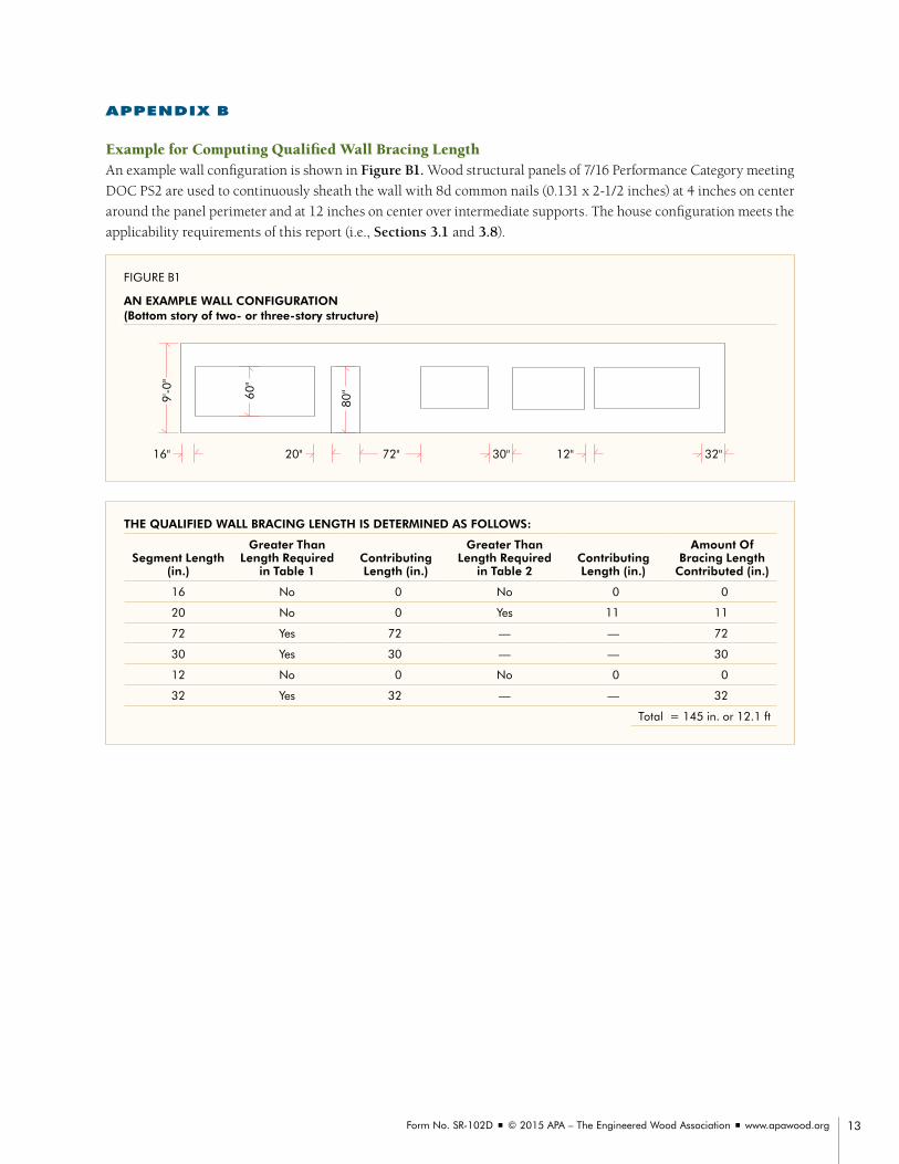
APPENDIX B
Example for Computing Qualified Wall Bracing Length AnexamplewallconfigurationisshowninFigure B1. Woodstructuralpanelsof7/16PerformanceCategorymeeting
DOCPS2areusedtocontinuouslysheaththewallwith8dcommonnails(0.131x2-1/2inches)at4inchesoncenter
aroundthepanelperimeterandat12inchesoncenteroverintermediatesupports.Thehouseconfigurationmeetsthe
applicabilityrequirementsofthisreport(i.e.,Sections 3.1 and3.8).
FIGURE B1
AN EXAMPLE WALL CONFIGURATION (Bottom story of two- or three-story structure)
72" 30"
80"60
"
9'-0
"
32"12"16" 20"
THE QUALIFIED WALL BRACING LENGTH IS DETERMINED AS FOLLOWS:
Segment Length (in.)
Greater Than Length Required
in Table 1Contributing Length (in.)
Greater Than Length Required
in Table 2Contributing Length (in.)
Amount Of Bracing Length
Contributed (in.)
16 No 0 No 0 0
20 No 0 Yes 11 11
72 Yes 72 — — 72
30 Yes 30 — — 30
12 No 0 No 0 0
32 Yes 32 — — 32
Total = 145 in. or 12.1 ft

APA Simplified Wall Bracing Method Using Wood Structural Panel Continuous Sheathing
APA – The Engineered Wood Association is an accredited certification body under ISO/IEC 17065 by Standards Council of Canada (SCC) and an accredited inspection agency by the International Code Council (ICC) International Accreditation Service (IAS) under ISO/IEC 17020. APA is also a testing organization accredited by IAS under ISO/IEC 17025. APA is a recognized testing laboratory by Miami-Dade County, and a Product Testing Laboratory, Product Quality Assurance Entity, and Product Validation Entity by the Florida Department of Business and Professional Regulation.
APA HEADQUARTERS7011 So. 19th St. n Tacoma, Washington 98466
(253) 565-6600 n Fax: (253) 565-7265
PRODUCT SUPPORT HELP DESK(253) 620-7400 n [email protected]
DISCLAIMERAPA System Report® is a trademark of APA – The Engineered Wood Association, Tacoma, Washington. The information contained herein is based on APA – The Engineered Wood Association’s continuing programs of laboratory testing, product research, and comprehensive field experience. Neither APA, nor its members make any warranty, expressed or implied, or assume any legal liability or responsibility for the use, application of, and/or reference to opinions, find-ings, conclusions, or recommendations included in this publication. Consult your local jurisdiction or design professional to assure compliance with code, construction, and performance require-ments. Because APA has no control over quality of workmanship or the conditions under which engineered wood products are used, it cannot accept responsibility for product performance or designs as actually constructed.
Form No. SR-102D/Revised September 2015