Embed Size (px)
Citation preview
REPRESENTING THE ENGINEERED WOOD INDUSTRY 7011 South 19th Street Tacoma, Washington 98466-5333 Phone: (253) 565-6600 Fax: (253) 565-7265 www.apawood.org
APA Report T2016L-24
Unrestrained Narrow Wall Bracing – Eight-Foot Tall Walls
©2016 APA – The Engineered Wood Association
by Edward L. Keith, P.E. Technical Services Division
July 20, 2016
Accredited by
TL-215
APA Report No. T2016L-24 July 20, 2016 Page 3 of 26 ©2016 APA – The Engineered Wood Association
TL-215
LABORATORY ACCREDITATIONS HELD BY APA
APA - The Engineered Wood Association is committed to providing its clients with high-quality service and information through documented test procedures and thorough, accurate collection of data. As a part of that commitment, a Quality Program has been established by APA based on the international document ISO/IEC 17025: General Requirements for the Competence of Testing and Calibration Laboratories. APA is accredited as a testing laboratory for specific scopes by the following agencies (other accreditations also shown where applicable):
International Accreditation Service (IAS), as an accredited Testing Laboratory (TL-215) under ISO/IEC 17025
International Accreditation Service (IAS), as an accredited Inspection Agency (AA-649) under ISO/IEC 17020
Standards Council of Canada (SCC), as an accredited Certification Body under ISO/IEC 17065
Japanese Ministry of Agriculture, Forestry, and Fisheries (MAFF), as a Registered Overseas Certification Body (ROCB) since June 21, 2006
California Office of the State Fire Marshal as Inspection Agency for products listed for the wildland and urban interface (WUI) areas (SFM Standard 12-7A-1)
City of Los Angeles, as a Compliance Assurance and Testing Agency (No. 22192) The Florida Department of Business and Professional Regulation, as a Product
Certification Agency (CER2512) The Florida Department of Business and Professional Regulation, as a Product Testing
Laboratory (TST2513) The Florida Department of Business and Professional Regulation, as a Product Quality
Assurance Entity (QUA2521) The Florida Department of Business and Professional Regulation, as a Product
Validation Entity (VAL3120) This report contains data generated through testing of engineered wood products according to various test methods accredited by organizations listed above. A list of accredited test methods is available upon request. Any test data that are derived from the standard test method(s) or accepted procedure(s) are noted in this report. Accreditation does not constitute endorsement of this report by the accreditation agency or government.
The precision and bias of the test methods given in this report are being established.
APA Report No. T2016L-24 July 20, 2016 Page 4 of 26 ©2016 APA – The Engineered Wood Association
Table of Contents 1. INTRODUCTION ..................................................................................................................... 5
2. DEVELOPMENT OF THE MODEL ......................................................................................... 5
3. MATERIALS AND METHODS ................................................................................................ 5
3.1 Test Frame ..................................................................................................................... 5 3.2 Wall Framing .................................................................................................................. 5 3.3 Wall Sheathing ............................................................................................................... 6 3.4 Fastening ........................................................................................................................ 6 3.5 Anchor bolts .................................................................................................................... 6 3.6 Hold-downs ..................................................................................................................... 6 3.7 Test Assemblies ............................................................................................................. 6 3.8 Test Methods .................................................................................................................. 7
4. RESULTS AND DISCUSSION ................................................................................................ 7
5. CONCLUSION ........................................................................................................................ 8
6. REFERENCES ........................................................................................................................ 9
7. APPENDICES ....................................................................................................................... 10
APA Report No. T2016L-24 July 20, 2016 Page 5 of 26 ©2016 APA – The Engineered Wood Association
1. INTRODUCTION
This report covers the testing conducted to supplement APA Reports T2012L-16 and T2012L-30. The original tests documented in the aforementioned reports were conducted to determine the structural contribution of continuously sheathed portal frames (IRC Methods CS-WSP/CS-PF) that do not meet the minimum bracing length requirements in the 2012 and 2015 International Residential Code (IRC) Table R602.10.5 – Minimum Length of Braced Wall Panels. Those tests were conducted with the test assembly attached to the test frame with hold-downs to simulate a restrained panel within a CS-WSP braced wall. This report covers a series of check tests conducted on similar assemblies as before except that these assemblies are not restrained from overturning by hold-downs. The purpose of this test was to determine if the same contribution from narrower elements can be expected in unrestrained systems.
2. DEVELOPMENT OF THE MODEL
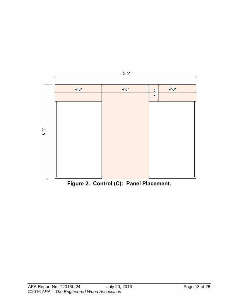
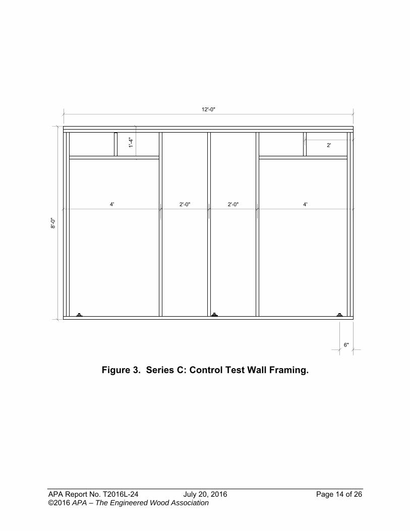
The methodology used was to first determine the capacity of an unrestrained (without hold-downs) 48-inch long full-height section in a 12-foot long wall. As this is the CS-WSP/CS-PH methodology, it is reasonable and conservative to place the full-height section in the middle of the 12-foot wall and place a 16-inch deep sheathed element above each of the open elements on the right and left side of the center-sheathed section. See Series C (Control) panel placement in Figure 2, Appendix A. This configuration simulates a traditionally-sized man-door-height opening on either side of the full-height element. The assembly was tested to failure with the load at various deflections recorded electronically. The capacity of the assembly was analyzed in accordance with ICC-ES AC130. As such, the load (VLRFD) at 0.60 inch (0.025H/Cd) was determined. From this load, the design capacity (VASD) and corresponding deflection was determined for the control. The Control capacity determined the contribution of the 48-inch long element in any number of walls that contain a 48-inch long element plus narrow-length elements (see Figure 4 in Appendix A for wall-framing details). While the original tests in APA Reports T2012L-16 and T2012L-30 were conducted on 9-foot and 8-foot tall walls, respectively, this check test was only conducted on 8-foot tall walls. This was determined to be the limiting case as the contribution to the strength and stiffness of the walls of the short panel segments above the doorways in the 8-foot walls (1’-4” vertical dimension for the 8-foor walls vs. a 2’-4” dimension on the 9-foot walls) was deemed to contribute less to the overall capacity of the test assemblies. As such the results of the 8-foot wall tests will be conservative for taller walls.
3. MATERIALS AND METHODS
3.1 Test Frame
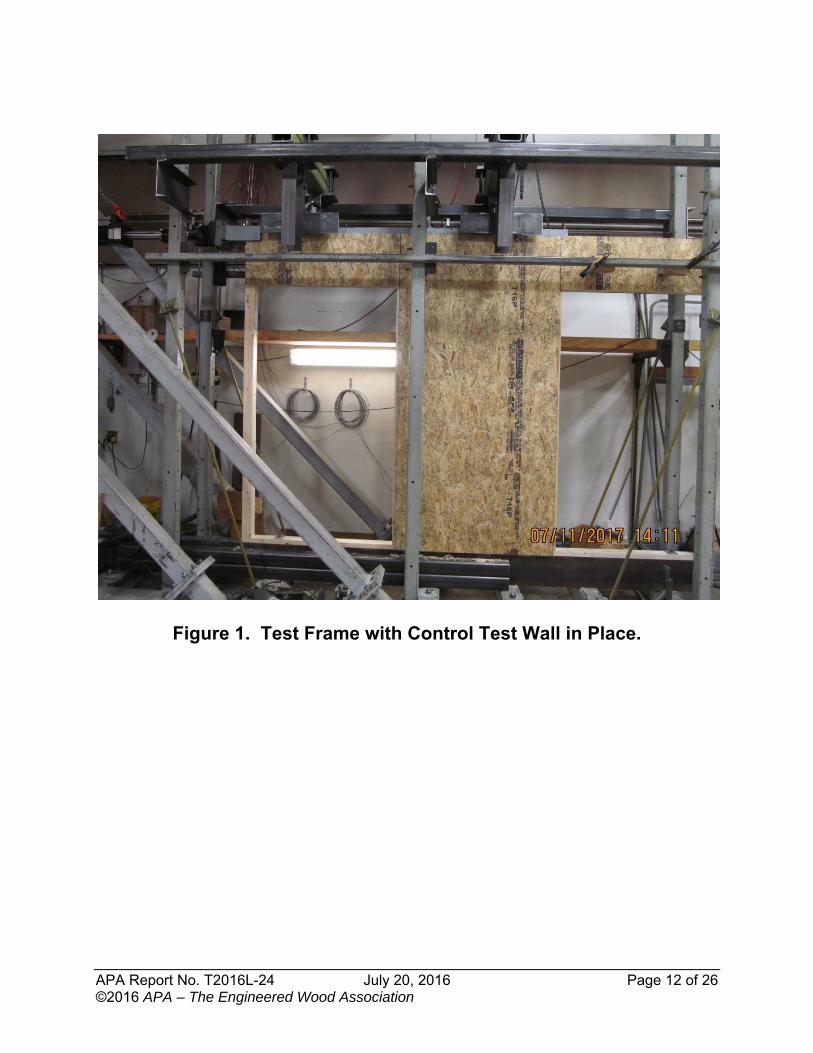
Testing was conducted on the cyclic load test frame at the APA Research Center in Tacoma, WA, as shown in Figure 1, Appendix A. 3.2 Wall Framing
Wall framing was 2x4 framing, 8 feet in height, SPF #2 or better. All plates were full length (12 feet or 11 feet-4 inches). The wall length was shortened to 11 feet-4 inches when testing 20-
APA Report No. T2016L-24 July 20, 2016 Page 6 of 26 ©2016 APA – The Engineered Wood Association
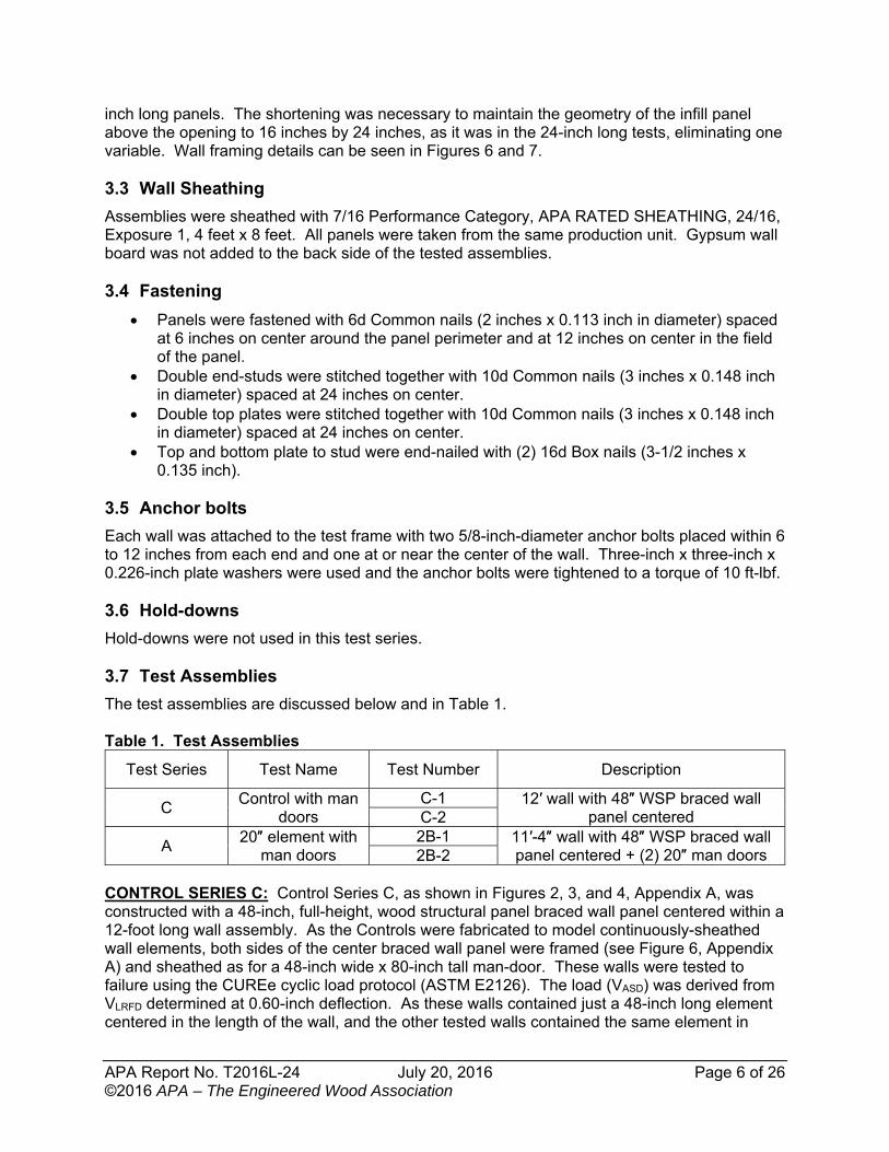
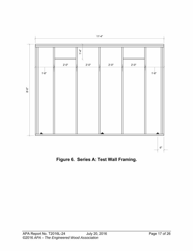
inch long panels. The shortening was necessary to maintain the geometry of the infill panel above the opening to 16 inches by 24 inches, as it was in the 24-inch long tests, eliminating one variable. Wall framing details can be seen in Figures 6 and 7. 3.3 Wall Sheathing
Assemblies were sheathed with 7/16 Performance Category, APA RATED SHEATHING, 24/16, Exposure 1, 4 feet x 8 feet. All panels were taken from the same production unit. Gypsum wall board was not added to the back side of the tested assemblies. 3.4 Fastening
Panels were fastened with 6d Common nails (2 inches x 0.113 inch in diameter) spaced at 6 inches on center around the panel perimeter and at 12 inches on center in the field of the panel.
Double end-studs were stitched together with 10d Common nails (3 inches x 0.148 inch in diameter) spaced at 24 inches on center.
Double top plates were stitched together with 10d Common nails (3 inches x 0.148 inch in diameter) spaced at 24 inches on center.
Top and bottom plate to stud were end-nailed with (2) 16d Box nails (3-1/2 inches x 0.135 inch).
3.5 Anchor bolts
Each wall was attached to the test frame with two 5/8-inch-diameter anchor bolts placed within 6 to 12 inches from each end and one at or near the center of the wall. Three-inch x three-inch x 0.226-inch plate washers were used and the anchor bolts were tightened to a torque of 10 ft-lbf.
3.6 Hold-downs
Hold-downs were not used in this test series. 3.7 Test Assemblies
The test assemblies are discussed below and in Table 1. Table 1. Test Assemblies
Test Series Test Name Test Number Description
C Control with man
doors C-1 12′ wall with 48″ WSP braced wall
panel centered C-2
A 20″ element with
man doors 2B-1 11′-4″ wall with 48″ WSP braced wall
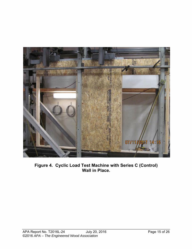
panel centered + (2) 20″ man doors 2B-2 CONTROL SERIES C: Control Series C, as shown in Figures 2, 3, and 4, Appendix A, was constructed with a 48-inch, full-height, wood structural panel braced wall panel centered within a 12-foot long wall assembly. As the Controls were fabricated to model continuously-sheathed wall elements, both sides of the center braced wall panel were framed (see Figure 6, Appendix A) and sheathed as for a 48-inch wide x 80-inch tall man-door. These walls were tested to failure using the CUREe cyclic load protocol (ASTM E2126). The load (VASD) was derived from VLRFD determined at 0.60-inch deflection. As these walls contained just a 48-inch long element centered in the length of the wall, and the other tested walls contained the same element in
APA Report No. T2016L-24 July 20, 2016 Page 7 of 26 ©2016 APA – The Engineered Wood Association
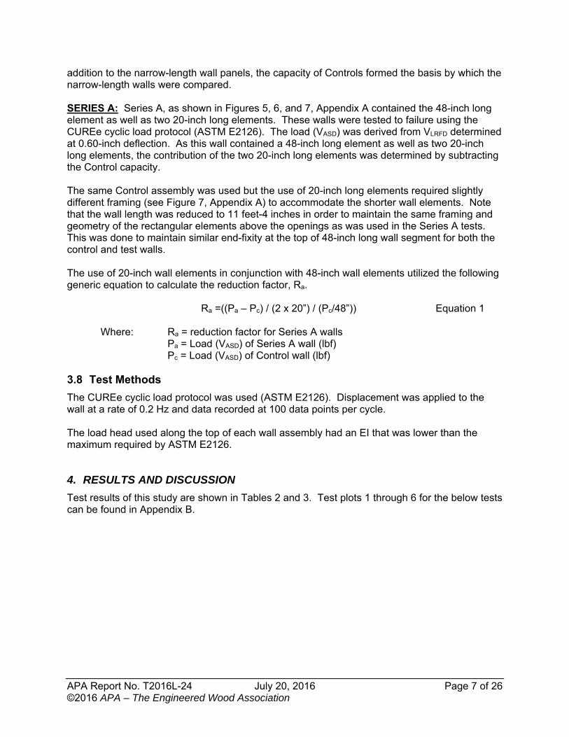
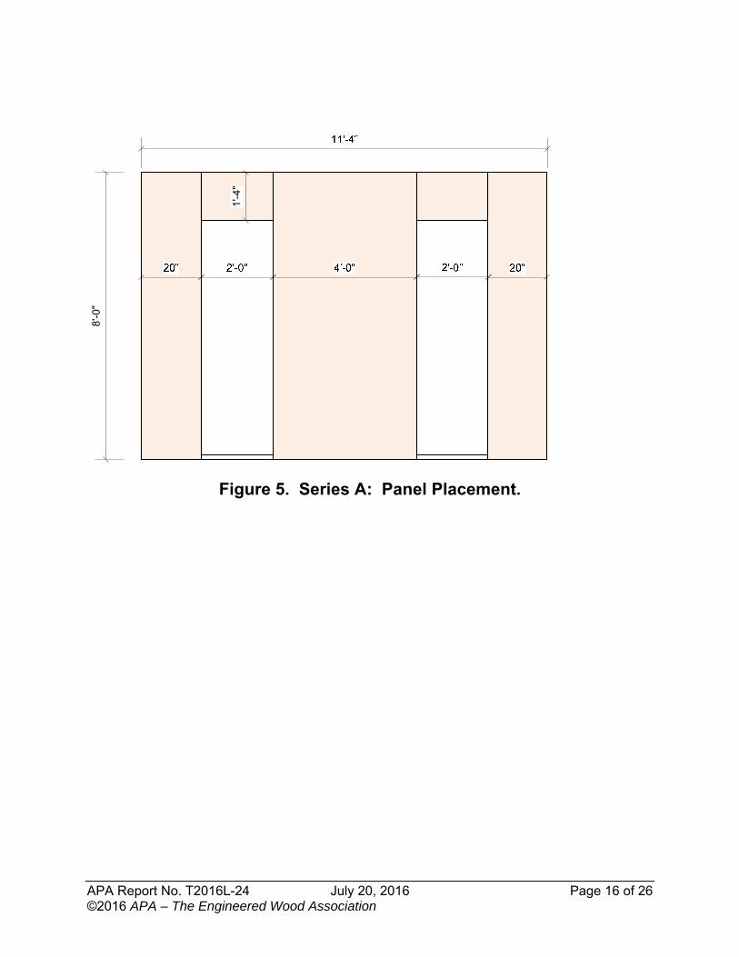
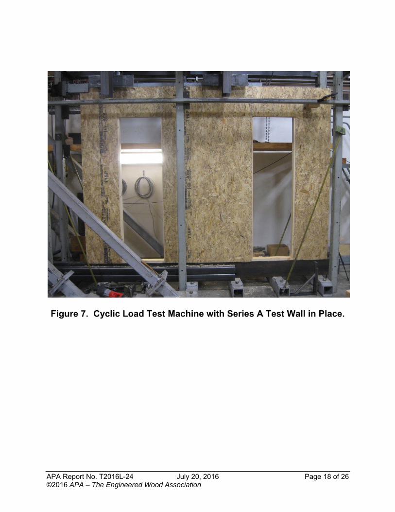
addition to the narrow-length wall panels, the capacity of Controls formed the basis by which the narrow-length walls were compared. SERIES A: Series A, as shown in Figures 5, 6, and 7, Appendix A contained the 48-inch long element as well as two 20-inch long elements. These walls were tested to failure using the CUREe cyclic load protocol (ASTM E2126). The load (VASD) was derived from VLRFD determined at 0.60-inch deflection. As this wall contained a 48-inch long element as well as two 20-inch long elements, the contribution of the two 20-inch long elements was determined by subtracting the Control capacity. The same Control assembly was used but the use of 20-inch long elements required slightly different framing (see Figure 7, Appendix A) to accommodate the shorter wall elements. Note that the wall length was reduced to 11 feet-4 inches in order to maintain the same framing and geometry of the rectangular elements above the openings as was used in the Series A tests. This was done to maintain similar end-fixity at the top of 48-inch long wall segment for both the control and test walls. The use of 20-inch wall elements in conjunction with 48-inch wall elements utilized the following generic equation to calculate the reduction factor, Ra.
Ra =((Pa – Pc) / (2 x 20”) / (Pc/48”)) Equation 1
Where: Ra = reduction factor for Series A walls Pa = Load (VASD) of Series A wall (lbf) Pc = Load (VASD) of Control wall (lbf) 3.8 Test Methods
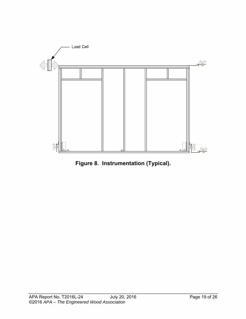
The CUREe cyclic load protocol was used (ASTM E2126). Displacement was applied to the wall at a rate of 0.2 Hz and data recorded at 100 data points per cycle. The load head used along the top of each wall assembly had an EI that was lower than the maximum required by ASTM E2126.
4. RESULTS AND DISCUSSION
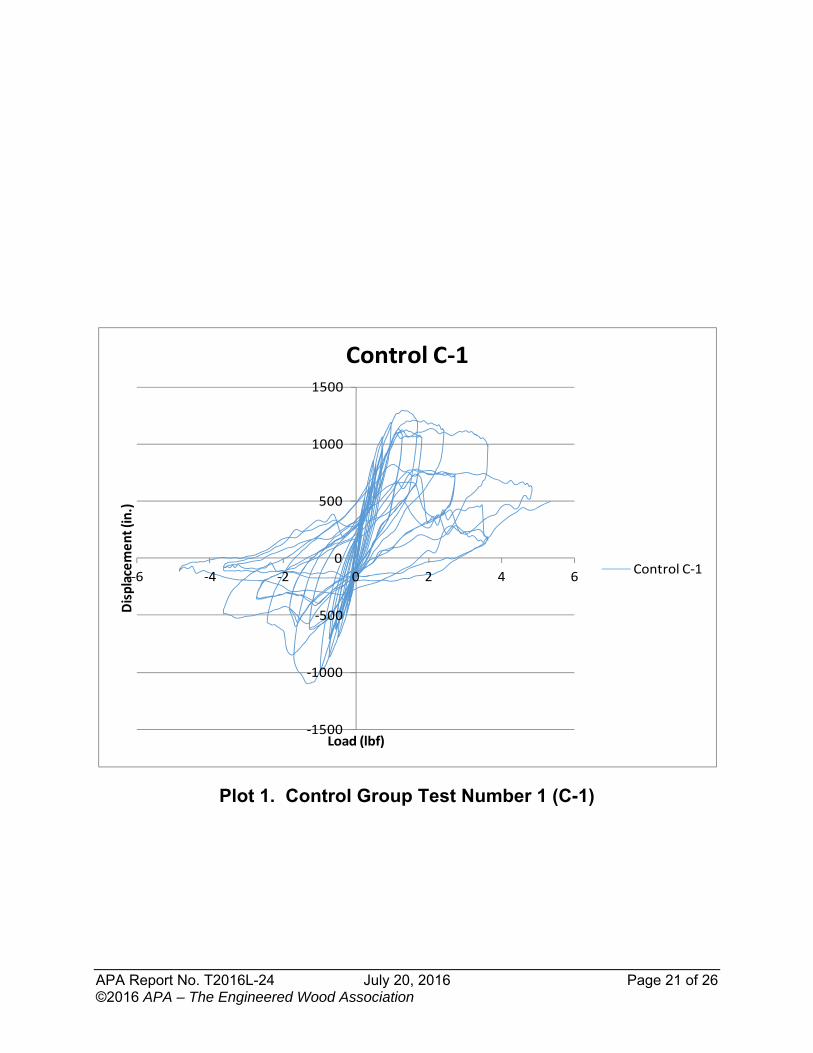
Test results of this study are shown in Tables 2 and 3. Test plots 1 through 6 for the below tests can be found in Appendix B.
APA Report No. T2016L-24 July 20, 2016 Page 8 of 26 ©2016 APA – The Engineered Wood Association
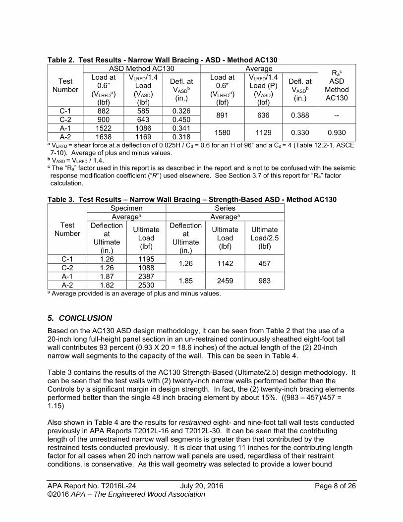
Table 2. Test Results - Narrow Wall Bracing - ASD - Method AC130
Test Number
ASD Method AC130 Average Ra
c ASD
Method AC130
Load at 0.6”
(VLRFDa)
(lbf)
VLRFD/1.4 Load (VASD) (lbf)
Defl. at VASD
b (in.)
Load at 0.6″
(VLRFDa)
(lbf)
VLRFD/1.4 Load (P)
(VASD) (lbf)
Defl. at VASD
b (in.)
C-1 882 585 0.326 891 636 0.388 --
C-2 900 643 0.450 A-1 1522 1086 0.341
1580 1129 0.330 0.930 A-2 1638 1169 0.318
a VLRFD = shear force at a deflection of 0.025H / Cd = 0.6 for an H of 96″ and a Cd = 4 (Table 12.2-1, ASCE 7-10). Average of plus and minus values.
b VASD = VLRFD / 1.4. c The “Ra” factor used in this report is as described in the report and is not to be confused with the seismic response modification coefficient (“R”) used elsewhere. See Section 3.7 of this report for “Ra” factor calculation.
Table 3. Test Results – Narrow Wall Bracing – Strength-Based ASD - Method AC130
Test Number
Specimen Series Averagea Averagea
Deflection at
Ultimate (in.)
Ultimate Load (lbf)
Deflection at
Ultimate (in.)
Ultimate Load (lbf)
Ultimate Load/2.5
(lbf)
C-1 1.26 1195 1.26 1142 457
C-2 1.26 1088 A-1 1.87 2387
1.85 2459 983 A-2 1.82 2530
a Average provided is an average of plus and minus values.
5. CONCLUSION
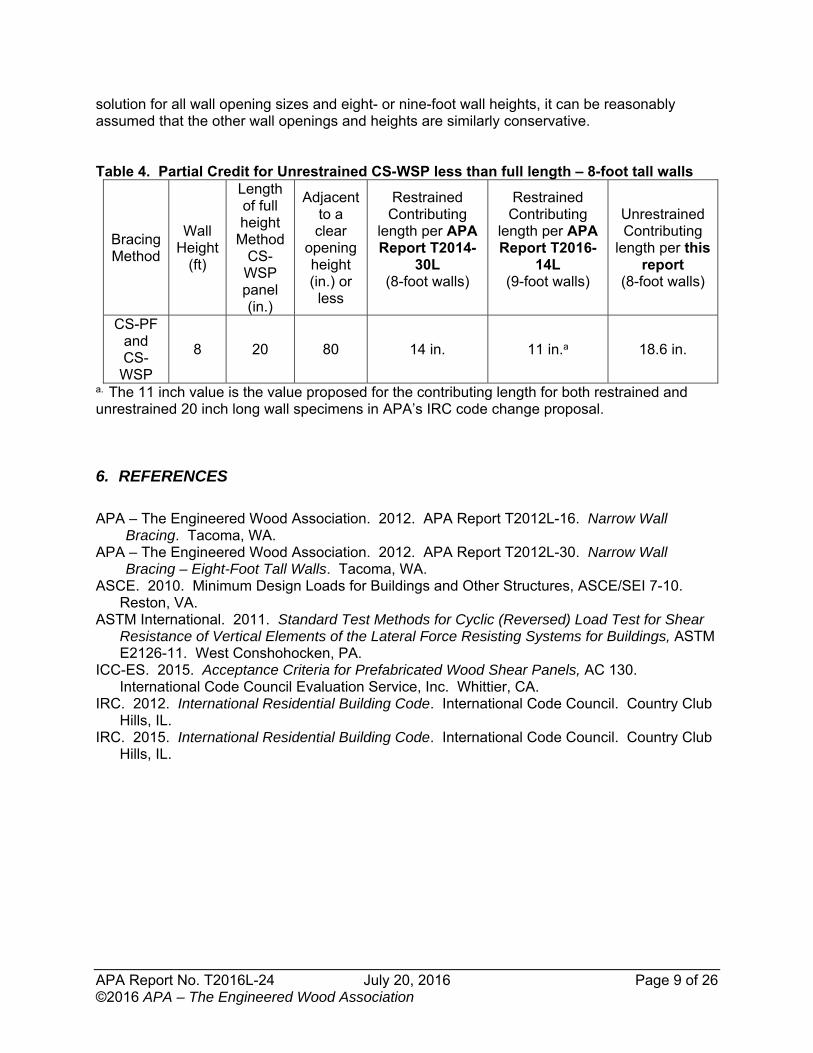
Based on the AC130 ASD design methodology, it can be seen from Table 2 that the use of a 20-inch long full-height panel section in an un-restrained continuously sheathed eight-foot tall wall contributes 93 percent (0.93 X 20 = 18.6 inches) of the actual length of the (2) 20-inch narrow wall segments to the capacity of the wall. This can be seen in Table 4. Table 3 contains the results of the AC130 Strength-Based (Ultimate/2.5) design methodology. It can be seen that the test walls with (2) twenty-inch narrow walls performed better than the Controls by a significant margin in design strength. In fact, the (2) twenty-inch bracing elements performed better than the single 48 inch bracing element by about 15%. ((983 – 457)/457 = 1.15) Also shown in Table 4 are the results for restrained eight- and nine-foot tall wall tests conducted previously in APA Reports T2012L-16 and T2012L-30. It can be seen that the contributing length of the unrestrained narrow wall segments is greater than that contributed by the restrained tests conducted previously. It is clear that using 11 inches for the contributing length factor for all cases when 20 inch narrow wall panels are used, regardless of their restraint conditions, is conservative. As this wall geometry was selected to provide a lower bound
APA Report No. T2016L-24 July 20, 2016 Page 9 of 26 ©2016 APA – The Engineered Wood Association
solution for all wall opening sizes and eight- or nine-foot wall heights, it can be reasonably assumed that the other wall openings and heights are similarly conservative. Table 4. Partial Credit for Unrestrained CS-WSP less than full length – 8-foot tall walls
Bracing Method
Wall Height
(ft)
Length of full height
Method CS-WSP panel (in.)
Adjacent to a clear
opening height (in.) or
less
Restrained Contributing
length per APA Report T2014-
30L (8-foot walls)
Restrained Contributing
length per APA Report T2016-
14L (9-foot walls)
Unrestrained Contributing
length per this report
(8-foot walls)
CS-PF and CS-
WSP
8 20 80 14 in. 11 in.a 18.6 in.
a. The 11 inch value is the value proposed for the contributing length for both restrained and unrestrained 20 inch long wall specimens in APA’s IRC code change proposal.
6. REFERENCES
APA – The Engineered Wood Association. 2012. APA Report T2012L-16. Narrow Wall
Bracing. Tacoma, WA. APA – The Engineered Wood Association. 2012. APA Report T2012L-30. Narrow Wall
Bracing – Eight-Foot Tall Walls. Tacoma, WA. ASCE. 2010. Minimum Design Loads for Buildings and Other Structures, ASCE/SEI 7-10.
Reston, VA. ASTM International. 2011. Standard Test Methods for Cyclic (Reversed) Load Test for Shear
Resistance of Vertical Elements of the Lateral Force Resisting Systems for Buildings, ASTM E2126-11. West Conshohocken, PA.
ICC-ES. 2015. Acceptance Criteria for Prefabricated Wood Shear Panels, AC 130. International Code Council Evaluation Service, Inc. Whittier, CA.
IRC. 2012. International Residential Building Code. International Code Council. Country Club Hills, IL.
IRC. 2015. International Residential Building Code. International Code Council. Country Club Hills, IL.
APA Report No. T2016L-24 July 20, 2016 Page 10 of 26 ©2016 APA – The Engineered Wood Association
7. APPENDICES
List of Appendices
Appendix A: Figures……………………………………………………………………………8 Pages Appendix B: Test Plots …………………………………………………………….……....….6 Pages
APA Report No. T2016L-24 July 20, 2016 Page 11 of 26 ©2016 APA – The Engineered Wood Association
Appendix A: Figures (8 pages)
APA Report No. T2016L-24 July 20, 2016 Page 12 of 26 ©2016 APA – The Engineered Wood Association
Figure 1. Test Frame with Control Test Wall in Place.
APA Report No. T2016L-24 July 20, 2016 Page 13 of 26 ©2016 APA – The Engineered Wood Association
Figure 2. Control (C): Panel Placement.
APA Report No. T2016L-24 July 20, 2016 Page 14 of 26 ©2016 APA – The Engineered Wood Association
Figure 3. Series C: Control Test Wall Framing.
8'-0
"
12'-0"
1'-4
"
6"
4'2'-0"2'-0"4'
2'
APA Report No. T2016L-24 July 20, 2016 Page 15 of 26 ©2016 APA – The Engineered Wood Association
Figure 4. Cyclic Load Test Machine with Series C (Control) Wall in Place.
APA Report No. T2016L-24 July 20, 2016 Page 16 of 26 ©2016 APA – The Engineered Wood Association
Figure 5. Series A: Panel Placement.
8'-0
"
1'-4
"
APA Report No. T2016L-24 July 20, 2016 Page 17 of 26 ©2016 APA – The Engineered Wood Association
Figure 6. Series A: Test Wall Framing.
8'-0
"
11'-4"
1'-4
"
6"
1'-8"
2'-0" 2'-0" 2'-0" 2'-0"
1'-8"
APA Report No. T2016L-24 July 20, 2016 Page 18 of 26 ©2016 APA – The Engineered Wood Association
Figure 7. Cyclic Load Test Machine with Series A Test Wall in Place.
APA Report No. T2016L-24 July 20, 2016 Page 19 of 26 ©2016 APA – The Engineered Wood Association
Figure 8. Instrumentation (Typical).
APA Report No. T2016L-24 July 20, 2016 Page 20 of 26 ©2016 APA – The Engineered Wood Association
Appendix B: Test Plots (6 Pages)
APA Report No. T2016L-24 July 20, 2016 Page 21 of 26 ©2016 APA – The Engineered Wood Association
Plot 1. Control Group Test Number 1 (C-1)
‐1500
‐1000
‐500
0
500
1000
1500
‐6 ‐4 ‐2 0 2 4 6
Displacement (in.)
Load (lbf)
Control C‐1
Control C‐1
APA Report No. T2016L-24 July 20, 2016 Page 22 of 26 ©2016 APA – The Engineered Wood Association
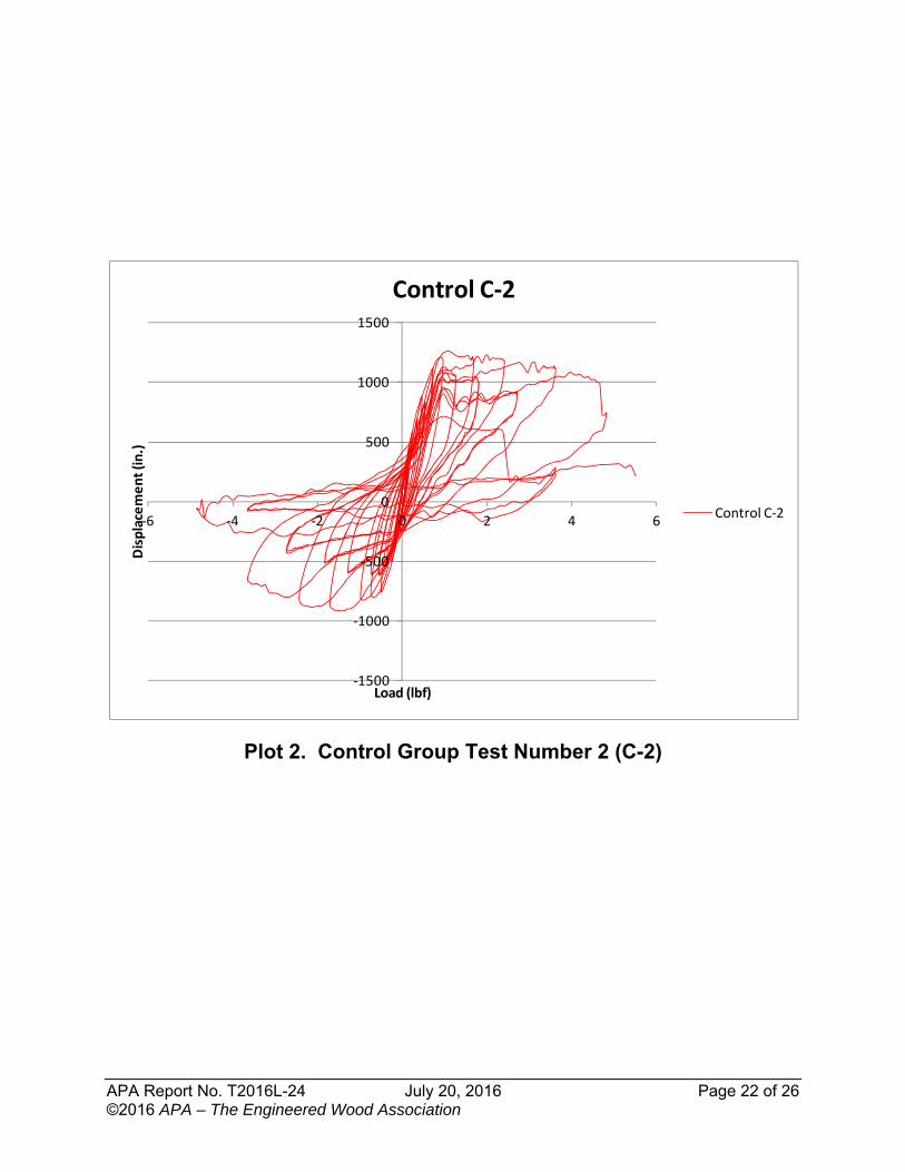
Plot 2. Control Group Test Number 2 (C-2)
‐1500
‐1000
‐500
0
500
1000
1500
‐6 ‐4 ‐2 0 2 4 6
Displacement (in.)
Load (lbf)
Control C‐2
Control C‐2
APA Report No. T2016L-24 July 20, 2016 Page 23 of 26 ©2016 APA – The Engineered Wood Association
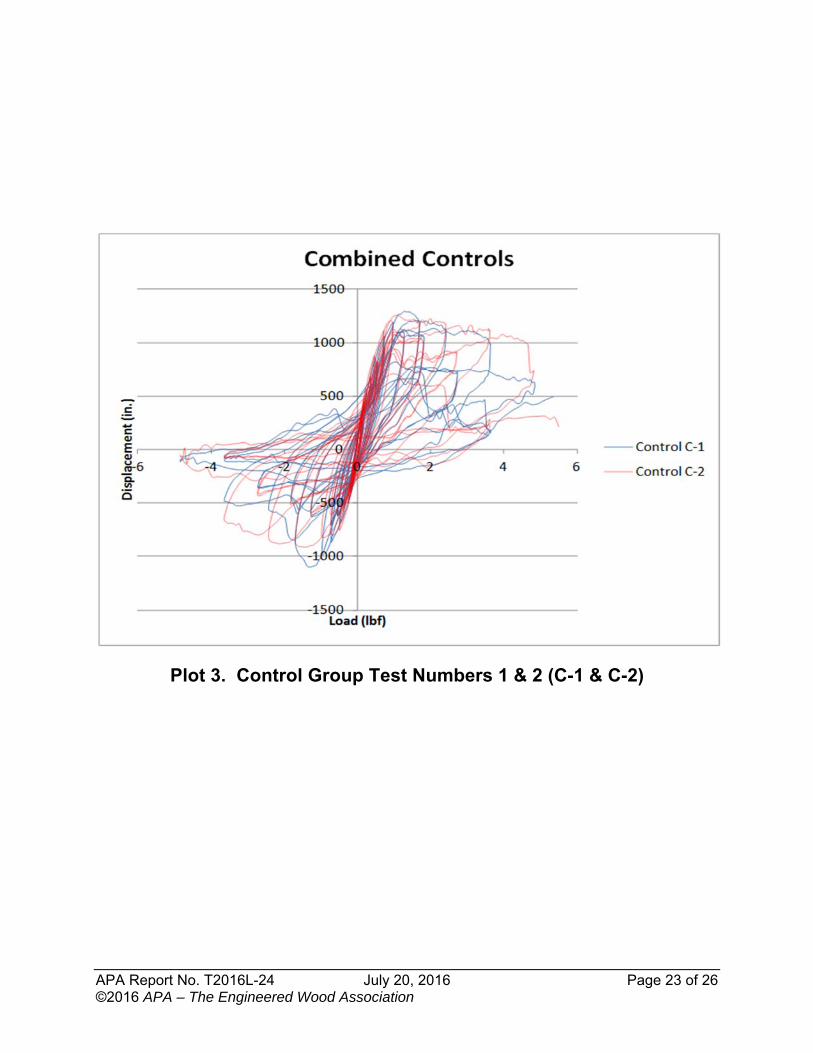
Plot 3. Control Group Test Numbers 1 & 2 (C-1 & C-2)
APA Report No. T2016L-24 July 20, 2016 Page 24 of 26 ©2016 APA – The Engineered Wood Association
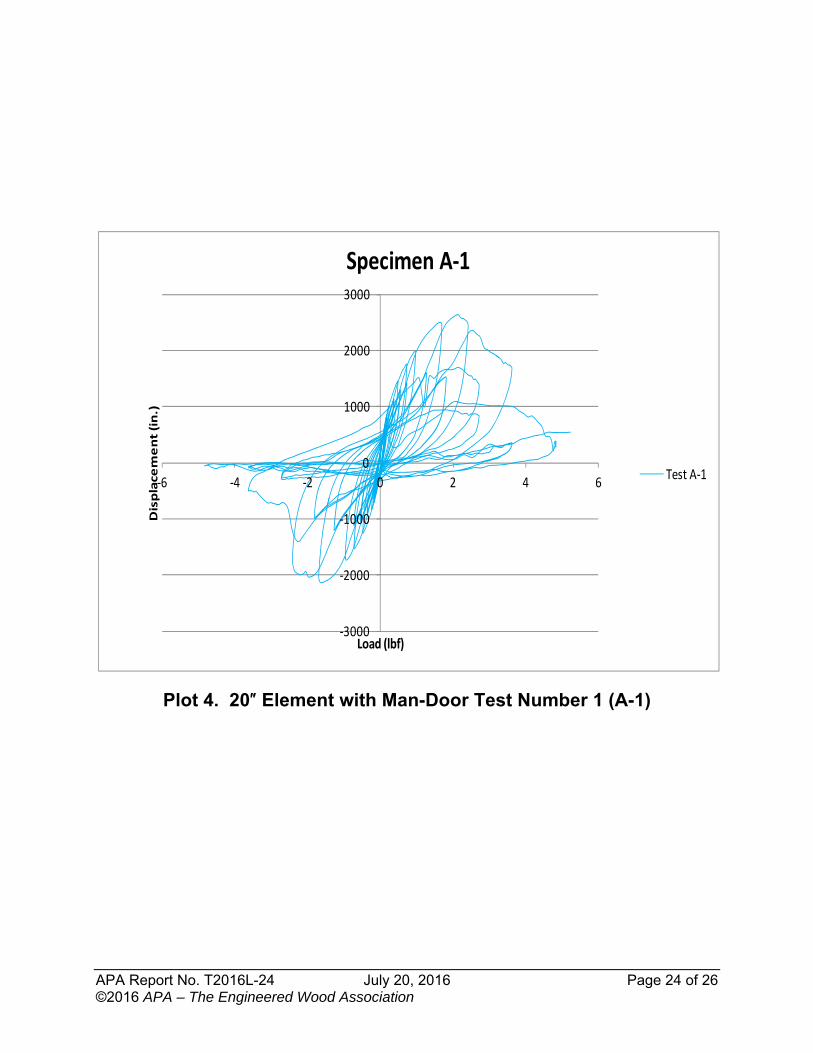
Plot 4. 20″ Element with Man-Door Test Number 1 (A-1)
‐3000
‐2000
‐1000
0
1000
2000
3000
‐6 ‐4 ‐2 0 2 4 6
Displacement (in.)
Load (lbf)
Specimen A‐1
Test A‐1
APA Report No. T2016L-24 July 20, 2016 Page 25 of 26 ©2016 APA – The Engineered Wood Association
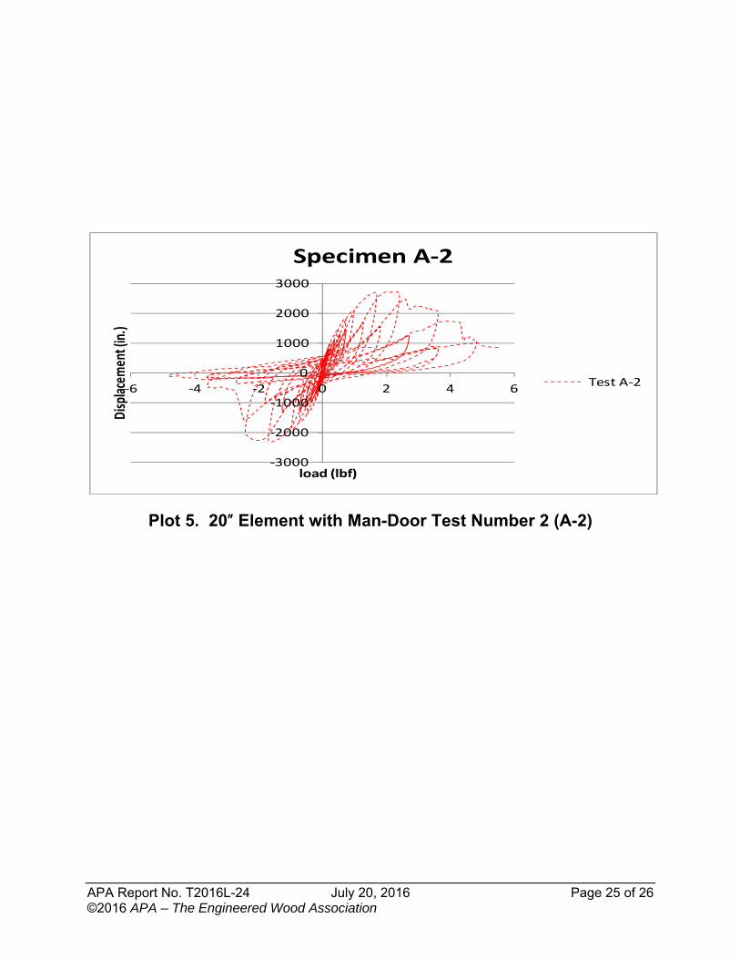
Plot 5. 20″ Element with Man-Door Test Number 2 (A-2)
‐3000
‐2000
‐1000
0
1000
2000
3000
‐6 ‐4 ‐2 0 2 4 6
Displacemen
t (in.)
load (lbf)
Specimen A‐2
Test A‐2
APA Report No. T2016L-24 July 20, 2016 Page 26 of 26 ©2016 APA – The Engineered Wood Association
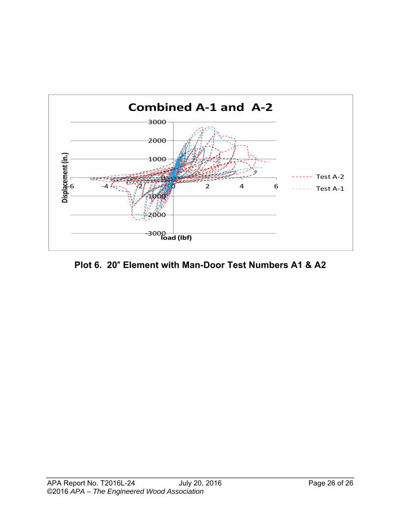
Plot 6. 20″ Element with Man-Door Test Numbers A1 & A2
‐3000
‐2000
‐1000
0
1000
2000
3000
‐6 ‐4 ‐2 0 2 4 6
Displacem
ent (in.)
load (lbf)
Combined A‐1 and A‐2
Test A‐2
Test A‐1