Embed Size (px)
Citation preview

AP42 Section 7.1
Related : 14
Title: Coal
Review of Hydrocarbon Emissions Related to
Tar Pitch. Includes pitch vapor pressure data and Antoine's coefficients.
EF Bart, et al. Allied Chemical Corporation 1980

I ._ ,.. ? i
e! ,/..'. .
i;. '.,. , : _..:, '">,U<>j.
r'.:.. . , , T . < , i l i -:*., $0 , i .#
1 ....
. . ..
R E V I E W OF HYDROCMSON E M I S S I O N S
RELATED TO COAL TAR PITCH
E. F. Bar t , S. A. V i s n i c , P . A. C e r r i a
A l l i e d Chemical Corpo ra t i on Morr istown, New Je rsey 07960
Sumnary
.. . - . .. ..
.. .
Coal t a r p i t c h i s used p r i m a r i l y as a b i n d e r i n t h e manufacture of carbon e lec t rodes f o r the aluminum and s t e e l i n d u s t r i e s . The p i t c h repre- sents the main product from t h e cont inuous, high-temperature d i s t i l l a t i o n of coke oven t a r . The p i t c h i s produced and g e n e r a l l y handled as a l i q u i d a t h i g h temperatures, thus r e s u l t i n g i n a p o t e n t i a l f o r hydrocarbon emissions d u r i n g i t s handl ing.
An ever - i nc reas ing need f o r c o n t r o l o f hydrocarbon emissions has r e s u l t e d f o r process and storage equipment s ince amendments were made i n 1977 t o the Clean A i r Act. W i th in the n e x t severa l years, most i n d u s t r i e s w i l l be faced w i t h requirements f o r t h e i n s t a l l a t i o n o f a i r p o l l u t i o n con- t r o l equipment. Th is paper deals w i t h t h e types o f emissions and methods used i n q u a n t i f y i n g and c o n t r o l l i n g emiss ions f rom coal t a r p i t c h storage equipment. To b e t t e r understand the n a t u r e o f coal t a r p i t c h , a b r i e f d e s c r i p t i o n i s g iven of i t s o r i g i n , chemis t r y and phys i ca l p roper t i es .
Coal Tar D i s t i l l a t i o n
Coal t a r p i t c h i s the residue from t h e d i s t i l l a t i o n of coal t a r and I t i s a complex, b i tuminous sub- represents from 30% t o 60% of the t a r .
stance and has been est imated t o c o n t a i n about 5,000 compounds. O f these, l e s s than 130 have been i s o l a t e d and i d e n t i f i e d .
The present-day process f o r f r a c t i o n a t i n g coa l t a r p r i m a r i l y used i n i n d u s t r y i s cont inuous d i s t i l l a t i o n . f rom t h e coal t a r . When coal t a r i s rece ived , i t con ta ins f rom 3% t o 10% water. s torage tank through a se r ies o f heat exchangers t o increase t h e temperature f rom about 175OF t o about 40OOF. The p r i m a r y heat source i s supp l i ed by the o i l and p i t c h products l eav ing the d i s t i l l a t i o n process. A steam heater , o r small furnace, i s used t o prov ide any secondary hea t requi red. t a r en te rs a f r a c t i o n a t i n g column-vapor box arrangement i n which t h e water and l i g h t o i l are vaporized. column and pass through a condensing s:dstem. i s separated as a r e s u l t o f the d i f f e r e n c e i n t h e i r s p e c i f i c g r a v i t i e s . Some o f t h e l i g h t o i l i s r e f l u x e d back t o t h e column i n o rde r t o c o n t r o l the top pf column temperature.
The f i r s t s t e p i s t h e removal of water
This water i s genera l l y removed by pumping t h e coal t a r from a
The 4OO0F
The vapors e x i t t h e top of t h e d i s t i l l a t i o n The l i g h t o i l - w a t e r m ix tu re
The water, which i s contaminated w i t h phenol ic
S i 1

and amnonia compounds, i s f ed t o a water t reatment f a c i l i t y . The d r y t a r t h a t e x i t s t h e vapor box i s c a l l e d dehydrated t a r and conta ins approx i - m a t e l y 0.1% water o r less.
The second s t e p i n t h e process i nvo l ves h e a t i n g the d r y t a r t o a temperature of 6OO0F t o 65OoF i n a furnace t o remove approximately 20% o f t h e l i g h t e r b o i l i n g f r a c t i o n s (one and two- r i ng compounds) present i n t h e c o a l t a r . Th is p o r t i o n o f the d i s t i l l a t e i s o f ten c a l l e d chemical o i l , and c o n t a i n s l o w - b o i l i n g t a r ac ids and naphthalene. f r a c t i o n a t i n g column t h a t may be opera t i ng a t reduced pressure. genera l purpose of t h e column i s t o separate t h e vapors t h a t f l ash i n t o two o r t h r e e f r a c t i o n s t h a t a r e f u r t h e r processed t o produce h i g h - p u r i t y naphthalene, t a r ac ids, and creosote o i l components. The vapors are con- densed w i t h a p o r t i o n o f t h e condensate being r e f l u x e d i n o rde r t o main- t a i n t h e t o p o f column temperatures as desired. o p e r a t i o n i s c a l l e d topped t a r .
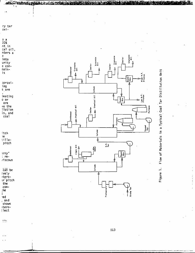
The t h i r d s tep i s removing another d i s t i l l a t e which conta ins approxi- m a t e l y 30% o f t h e h i g h e r b o i l i n g f r a c t i o n s ( th ree , four, and f i v e - r i n g compounds). acenaphthene, carbazole, f l uo rene , phenanthrene, pyrene, anthracene, f l u o r a n t h r e n e , chrysene and picene. The topped t a r enters a f r a c t i o n a t i n g column-vapor box arrangement where t h e vapors a r e separated i n t o two o r t h r e e components. As i n t h e o t h e r two steps, condensing and r e f l u x are used t o m a i n t a i n des i red temperatures. c a p a b i l i t y t o operate a t reduced pressures i n t h i s step. The d i s t i l l a t i o n r e s u l t s i n t h e p roduc t i on o f l i g h t creosote o i l s , heavy creosote o i l s , and coal t a r p i t c h . F igu re 1 recaps t h e f l o w o f m a t e r i a l s i n a t y p i c a l coal t a r d i s t i l l a t i o n u n i t .
P h y s i c a l P r o p e r t i e s and t h e Chemical S t r u c t u r e
depend on severa l factors . Among these fac to rs a r e the nature of the c o k i n g process from which the t a r i s der ived, t h e n a t u r e o f the d i s t i l l a - t i o n process by which t h e p i t c h i s separated, and whether t h e f i n a l p i t c h i s a b lend of p i t ches , o r a d i r e c t product.
A l l p i t c h e s a r e brownish-black o r b lack i n c o l o r and have a " t a r r y " odor, p robab ly due t o t r a c e q u a n t i t i e s of naphthalene and phenol n o t re - moved d u r i n g t h e d i s t i l l a t i o n process. l i q u i d s a t room temperature t o m a t e r i a l s which a r e b r i t t l e so l i ds .
i s o l a t e d and analyzed a r e the d i s t i l l a t e o i l s . i d e n t i f i e d c o n s i s t ma in l y o f po l ynuc lea r aromat ic hydrocarbons o r hetero- c y c l i c compounds c o n t a i n i n g t h r e e t o s i x r i n g s . which i s s u f f i c i e n t l y v o l a t i l e t o d i s t i l l , appears t o be made up of the same o i l s which a r e present i n crude t a r , b u t are p a r t l y removed i n con- v e r t i n g t a r i n t o p i t c h . The major i s o l a t e d compounds progress, as the b o i l i n g range i s increased, f rom s i n g l e r i n g benzene, thiophene, and p y r i d i n e d e r i v a t i v e s t o those c o n t a i n i n g one s i x and one five-membered r i n g ( indene, i n d o l e ) , then t o t h e naphthalene and q u i n o l i n e ser ies, and f i n a l l y t o three-membered r i n g systems (anthracene, phenanthrene as shown i n 1966 i n Hoiberg ( 4 ) ) . It i s because of the comp lex i t y o f t h i s hetero- genous m i x t u r e t h a t coal t a r p i t c h i s so d i f f i c u l t t o completely c o l l e c t and analyze.
Th is h o t t a r enters a The
The t a r l eav ing t h i s
The p roduc t i s c a l l e d creosote o i 1. Pr imary components are
Most coal t a r d i s t i l l e r s have the
The chemical composi t ion and a l s o the phys i ca l p r o p e r t i e s of p i t c h
The p i t c h e s can range from viscous
The o n l y f r a c t i o n s o f p i t c h f rom which pure chemical compounds can be The compounds p o s i t i v e l y
The p a r t o f coal t a r p i t c h
512
I ..
r y t a r o x i -
o a 20%
~ .. n t i n c a l o i l , n t e r s a
i n t o u r i t y e con- main- i s
?
i p r o x i - i n g s are
m a t i n g o o r are
ve the 11 a t i o n : s , and coal
i t c h ?e c i l l a - p i t c h
?rry" ; re- i i scous
_ _ can be
i v e l y ? te ro- ?r - 'p i t ch the con-
:he I .ed
" . 0 - . * - :
"
* =. .. P C
L
" 4
, and shown
t te ro - I l e c t
513
u C 1
.r
C 0
u .r
m
.r c) v1
0 .r
L m
.I- - m 0 . v 7
m
n u
2,
.r
m c .r
u- 0
0) L =I
lL
m .r

Types o f Emissions f rom Storage Tanks
The phys i ca l p r o p e r t i e s and chemical composi t ion of coal t a r p i t c h d i c t a t e t h a t i t no rma l l y be s to red i n f i x e d r o o f storage tanks r a t h e r than f l o a t i n g r o o f tanks. Because of i t s h igh sof ten ing p o i n t and t h e tendency f o r i t s vapors t o condense and c r y s t a l l i z e , a f l o a t i n g roof storage tank i s n o t recomnended f o r fear of f o u l i n g of the seal and hence i m o b i l i z a t i o n o f the tank roof . We w i l l , t he re fo re , concentrate o n l y on emissions from the s torage o f coal t a r p i t c h i n f i xed roof tanks.
hydrocarbons escape t o the atmosphere. Evaporat ion losses from f i x e d roof tanks may be d i v i d e d i n t o two categor ies; b rea th ing l o s s and working loss. B rea th ing l o s s i s assoc iated wi th thermal expansion and c o n t r a c t i o n o f the vapor space r e s u l t i n g f rom t h e d a i l y temperature cyc le . vapors expe l l ed because of t h e t h e n a l expansion of e x i s t i n g vapors, and/or expansion caused by barometr ic pressure changes, and/or an increase i n t h e amount o f vapors f rom added vapor i za t i on i n t h e absence of l i q u i d l e v e l change, except t h a t which r e s u l t s from b o i l i n g as shown i n 1976 by Burkli'?
Hydrocarbon emissions, o r evaporat ion losses, occur when evaporated
They inc lude
I and Honerkamp (31. - Working l o s s i s assoc ia ted w i t h a change o f l i q u i d l e v e l i n the tank,
which may inc lude b o t h t h e displacement of vapor by a r i s i n g l i q u i d surface and t h e outbreath o f vapor fo l l ow ing a r a p i d wi thdrawal . ma te r ia l s , t h e f i l l i n g l o s s occurs when t h e l i q u i d t rans fe r red i n t o t h e s torage tank d i sp laces an equal volume of a i r , sa tu ra ted o r n e a r l y sa tu ra ted w i t h hydrocarbons, and vents the a i r t o t h e atmosphere. coal t a r p i t c h , because of i t s h i g h temperature, a l s o has working losses from the expansion o f t h e vapor space due t o an increase i n temperature caused by the hot , incoming p i t c h . This i n i t i a l expansion o f t h e vapor space r e s u l t s i n the f o l l o w i n g :
( 1 ) The i n i t i a l r a p i d a i r expansion causes h i g h emission volume u n t i l t h e a i r i s d isplaced.
( 2 ) The a i r c o n t a c t i n g the i n i t i a l p i t c h vapors produces condensation and creates an aerosol .
For most l i q u i d
However,
Because of t h i s m i x t u r e o f a i r , aerosol and p i t c h vapor, and the l a r g e increase i n vapor volume, c o n t r o l o f p i t c h emissions becomes a d i f f e r e n t and d i f f i c u l t c o n t r o l problem.
Es t ima t ion of Emissions
Whet
Mathematical Methods
Several methods e x i s t f o r the q u a n t i f i c a t i o n o f emissions from storage tanks. f i x e d r o o f s torage tanks i s t h e A P I method ( 1 ) f o r b rea th ing losses and work ing losses. The equat ion f o r es t ima t ion o f b rea th ing losses i s :
The most w i d e l y accepted method f o r es t ima t ion of emissions from
Ly im 24 ( P ) 0.68 1.73 H0.51 O.5OF
P
tanks corre
Whe
o r i g i mater
Whe
Whf 1
514

' I i I
i t c h a- than endency
tank i s a t i o n o f rom t h e
r a t e d ed r o o f 9 loss. o f t h e
de , andfor i n t h e
eve1 B u r k l i n
e tank, sur face
l i q u i d t h e
However, x s e s t u r e apor
he l a r g e ? r e n t
.- - , I
.. .
storage from and . --
Where: Ly = breath ing l o s s ( b b l s f y r )
P = t r u e vapor pressure a t bu lk l i q u i d temperature ( p s i a )
0 = tank diameter ( f t )
H = average outage, i n c l u d i n g c o r r e c t i o n f o r roof volume ( f t )
T = average d a i l y ambient temperature change ( O F )
Fp = p a i n t f a c t o r
C = adjustment f a c t o r f o r smal l d iameter tanks
The preceding equat ion i s g e n e r a l l y app l i cab le f o r gasol ine storage For c o r r e c t i n g the losses f o r o the r ma te r ia l s , t h e fo l l ow ing tanks.
c o r r e c t i o n i s genera l l y used by t h e API: Lb = (+---)Ly 0 08 M
Where: Lb = b rea th ing l o s s ( b b l s l y r )
M = molecular weight o f vapor ( l b / l b mole)
W = condensed l i q u i d d e n s i t y o f vapor ( l b f g a l )
When d e n s i t y data f o r t h e condensed vapors cannot be obtained, the o r i g i n a l b rea th ing l o s s equat ion can be used f o r coal t a r p i t c h and o the r m a t e r i a l s by us ing t h e d e n s i t y o f the s to red l i q u i d . ' The equat ion becomes:
0.68 ,, 1.73 0.51 i 0;50 Fp c . .
Where:
Where:
Ly = b rea th ing loss ( l b / y r )
p - d e n s i t y of s to red l i q u i d ( l b / g a l )
The API equat ion ( 2 ) f o r e s t i m a t i n g working losses i s :
2.25 PV K t F = T r
F = working l o s s ( b b l s )
P = t r u e vapor pressure
. .
k l i q u i d temperature ( p s i )
V = volume o f l i q u i d pumped i n t o tank ( b b l s ) K t = tu rnove r f a c t o r
515
The same equat ion i s used t o c a l c u l a t e the working losses f o r tanks
Once again, should d e n s i t y data f o r the condensed vapors be i n -
c o n t a i n i n g o t h e r l i q u i d s by a d j u s t i n g i t w i t h t h e 0.08 M/!J term.
access ib le , t h e equa t ion can be used w i t h t h e l i q u i d dens i t y t o y i e l d : . .
I
E p 2.25 PV K t 10,000
Where: F = work ing loss ( l b l y r )
p = d e n s i t y of s t o r e d l i q u i d ( l b / g a l )
V = volume o f l i q u i d pumped i n t o tank ( g a l / y r )
Recent ly, f u r t h e r s tud ies i n 1978 by Wilson ( 7 ) have been conducted on t h e e s t i m a t i o n o f work ing losses. b a s i c assumptions of t h e API equat ion:
The s tud ies have evolved around t h e two
( 1 )
( 2 ) Every b a r r e l o f o i l pumped i n t o the tank d isp laces
The vapor space i n t h e tank i s saturated.
5.61 cub ic f e e t of vapor.
From f i e l d s tud ies , Wilson found t h a t bo th assumptions are i n c o r r e c t t h e m a j o r i t y of the t ime. For s torage tank operat ions, the amount of vapor fo rced o u t of t h e tank should o n l y be ca l cu la ted by t h e t o t a l upward move- ment of the l i q u i d l e v e l , s ince i n many cases, t h e l i q u i d i s pumped o u t a t t h e same t ime i t i s pumped i n t o t h e tank.
! I
The s tud ies by Wi lson a l s o showed t h a t t h e average vapor concen t ra t i on i n s torage tanks was 66% o f t h e t h e o r e t i c a l sa tu ra ted vapor concen t ra t i on . Using t h e 66% s a t u r a t i o n and the- t o t a l upward movement o f the l i q u i d l e v e l , t h e work ing l o s s equat ion becomes:
E = (1.2 x PVM
Where:
E = emissions ( l b s )
P = t r u e vapor pressure a t bu l k l i q u i d temperature ( p s i a )
M = mo lecu la r weight of vapors ( l b / l b mole)
V = volume of d i sp laced vapors ( s c f )
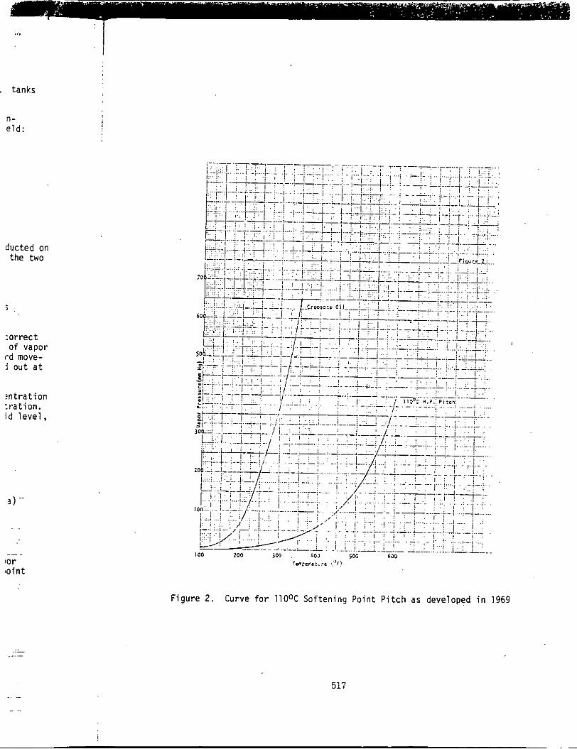
In t h e preceding b r e a t h i n g and working l o s s equa$ions, the vapor pressure f o r l i q u i d p i t c h i s used. p i t c h i s shown i n F igu re 2 as developed i n 1969 (6).
The curve f o r 110 C sof ten ing p o i n t
Figur
516
: I
. tanks
n- eld: !
ducted on the two
:orrect
rd move- i o u t a t
of vapor
!ntration : r a t ion . id l eve l ,
._ . lor toint
.. - .. ..
rs:er.:... !'+I
Figure 2 . Curve f o r llO°C Softening Point Pitch as developed i n 1969
517
~~
!

Another method f o r es t ima t ion of. working losses which has been used on coal t a r p i t c h s torage tanks i s a model based on t h e expansion o f the vapor space when h o t p i t c h i s pumped i n t o the tank as shown i n 1975 by Hooker (5). Since p i t c b i s pumped t o storage tanks a t temperatures any- where f rom 300 F t o 750 F, the expansion o f the vapor space and corres- ponding vapor emission i s much g rea te r than b rea th ing losses o r working losses due t o t h e displacement o f the vapors. This model, therefore, becomes u s e f u l f o r o b t a i n i n g t h e maximum emission r a t e when f i r s t pumping h o t p i t c h i n t o a r e l a t i v e l y c o l d e r storage tank. The method assumes t h a t t h e i n l e t t o the tank i s a submerged f i l l p ipe used t o reduce con tac t between t h e incoming p i t c h and the a i r space.
minute, o f t ime when pumping i n t o a tank i s est imated as fo l l ows : The volume o f p i t c h vapor g iven o f f over a sho r t i n t e r v a l , say one
Where:
E = vapor emissions (cubic fee t )
F = i n l e t p i t c h flow (gpm)
t s = vapor space temperature a t s t a r t of i n t e r v a l ( F)
A t s = change i n vapor space temperature d u r i n g t h e i n t e r v a l
V t = tank capac i t y ( g a l )
Vp = volume o f p i t c h i n tank a t s t a r t o f i n t e r v a l ( g a l )
0
( FJ
S i m p l i f y i n g the above equat ion gives:
The change in t h e vapor space temperature i s expressed as fo l lows:
7 Ats = m r E p 1 up ( t p - t s ) - AW UW ( t s - t a l WsH
U = heat t r a n s f e r c o e f f i c i e n t
A = hea t t r a n s f e r area (square ft.)
t = temperature (OF)
W = weight of vapors ( l b s )
BTU H = hea t capac i t y o f vapor (lb uF
sub a = ambient
sub p = p i t c h sur face
sub s = vapor space i n tank sub w = u n i n s u l a t e d w a l l and r o o f surface
hr. f t ( " Where:
TY! ' 1 .5 ani
cot a s an the ch,
u s t o t a l t e m i n temper p i t c h
Wher
essent
8; emittc which pressi
used
any- 'es- . i n g
mping t h a t
:t
t h e i by j
i one
!
r v a l
I
ws :
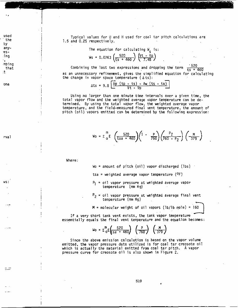
Typ ica l values f o r U and H used f o r coal t a r p i t c h c a l c u l a t i o n s a r e 1.5 and 0.25 respec t i ve l y .
The equat ion f o r c a l c u l a t i n q W- i s : - >
Ws = 0.0763 (ts5:a460) (w) , ' 520 Combining the l a s t two expressions and dropping the' term
tS + 460 as an unnecessary re f inement , g ives t h e s i m p l i f i e d equat ion f o r c a l c u l a t i n g the chanae i n vauor suace temuerature ( A t s ) : -
A (t - t s - Aw ( t s - t a A t S = 9.8 Vt - ) v p
Using no l a r g e r than one minute t ime i n t e r v a l s over a g iven t ime, t h e t o t a l vapor f l o w and t h e weighted average vapor temperature can be de- termined. By us ing t h e t o t a l vapor f low, the weighted average vapor temperature, and the f ie ld-measured f i n a l vent temperature, the amount of p i t c h ( o i l ) vapors e m i t t e d can be determined by t h e f o l l o w i n g expression:
Where:
Wo = amount of p i t c h ( o i l ) vapor discharged ( l b s )
t s a = weighted average vapor temperature (OF)
Pl = o i l vapor pressure a t weighted average vapor
p2 = o i l vapor pressure a t weighted average f i n a l vent
M = molecular weight o f o i l vapors ( l b / l b mole) = 160
temperature (m Hg)
temperature (mn Hg)
3 If a ve ry sho r t tank vent e x i s t s , the tank vapor temperature
e s s e n t i a l l y equals t h e f i n a l vent temperature and t h e equat ion becomes:
Since t h e above emission c a l c u l a t i o n i s based on t h e vapor volume emi t ted, t h e vapor pressure da ta u t i l i z e d i s f o r coal t a r creosote o i l which i s a c t u a l l y t h e m a t e r i a l em i t ted from coal t a r p i t c h . A vapor pressure curve f o r creosote o i l i s a l so shown i n F igu re 2 .
519 .. .

Sampling and A n a l y t i c a l Methods
from coal t a r p i t c h and o t h e r l i q u i d s torage tanks. method i s t h e c o l l e c t i o n o f vapors i n an evacuated b o t t l e . then analyzed u s i n g a gas chromatograph equipped w i t h a flame ion i . za t i on d e t e c t o r (FID). t h e a c t u a l mass r a t e of emi,ssi,ons i s obtai.ned.
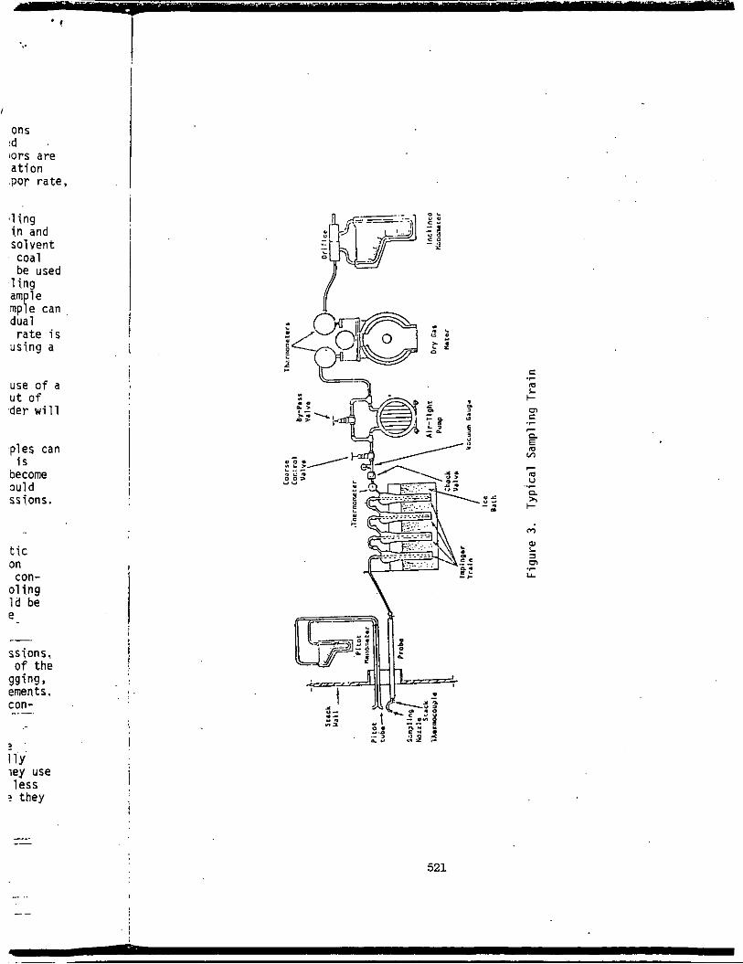
t i m e i s requ i red . p o r t a b l e vacuum pump t o condense and c o l l e c t the vapors i,n a known so lven t o r so l ven ts . A typi .ca1 sampling t r a i n i s shown i n Figure 3. Si.nce coal t a r p i t c h i s comprised o f mos t l y "heavier" hydrocarbons, hexane can be used as a s o l v e n t a l t hough cons ide ra t i on of s o l v e n t l o s s duri.ng t h e sampli.ng p e r i o d i s impor tant . A f t e r sample c o l l e c t i o n i n t h e so l ven t , t h e sample i s analyzed u s i n g a gas chromatograph w i t h a FID. The c o l l e c t e d sample can be f u r t h e r analyzed u s i n g a mss .spectrometer t o dist i .ngui ,sh i n d i v i d u a l compounds. However, thi.s i,s n o t r e q u i r e d if o n l y the mass emissi,on r a t e i s necessary. Gas f low r a t e s from a tank v e n t a r e g e n e r a l l y measured us ing a p i t o t tube.
Another method which i,s becoming more and more popular i s the use o f a p o r t a b l e hydrocarbon vapor analyzer. hydrocarbon concentrqt i ,on ( i n ppm) qnd when i n t e r f a c e d wi,th a recorder wi.11 show the d i f f e r e n t peaks i.n a chromatogram.
As a r e s u l t of the ease and speed o f these analyzers, many samples can be taken t o g i v e an accurate p i c t u r e o f t h e vapor cons t i t uen ts . because o f t h e g r e a t f l e x i b i l i t y of these u n i t s t h a t t h e i r use has become i n c r e a s i n g l y popular , as shown by t h e EPA's f j e l d use. p o s s i b l y become t h e approved method f o r determi.ning hydrocarbon emi.ssions.
Con t ro l €qui pment
p r e c i p i t a t o r s a r e t h e more comnon methods f o r c o n t r o l l i , n g hydrocarbon emissions from coal t a r p i t c h storage f a c i l i t i e s . densing systems can be u t i l i . z e d . c o i l s submerged i n a water bath. k e p t above 175oF t o p reven t the poss ib le p lugg ing of t h e c o i l b y the c r y s t a l l i z a t i o n of naphthalene and o t h e r compounds,
She1 1-and-tube condensers can a l s o be used t o reduce pl'tch emissions. Once agai,n, tempered Water must be employed t o prevent the pluggi.ng of the condenser. b u t i s used because o f t h e hi.gher e f f i c i e n c y and lower space req,uirements. Because of t h e i . r s m a l l e r si.ze, the shel l -and-tube condenser can be con- v e n i e n t l y l o c a t e d on t o p of t h e storage tank.
i m p r a c t i c a l . A i r - c o o l e d condensers f o r coal t a r p i t c h vapors a c t u a l l y have l a r g e d iameter v e n t p i p i n g arranged i n a c o i l - l i k e pa t te rn . t h e ambient a i r t o condense the p i t c h vapors. e f f i c i e n t than water-cooled condensers, b u t are advantageous because they a r e l e s s s u s c e p t i b l e t o pluggi.ng and do n o t need a water system.
Many methods have been used f o r determin ing hydrocarbon emissions One widely-used
The vapors are
Using t h e vapor concen t ra t i on and the tank vent vapor r a t e ,
In o r d e r t o o b t a i n a more r e p r e s e n t a t i v e sample, a longer sampling T h i s can be accomplished by u s i n g a sampling t ra i ,n and
The u n i t gi.ves a d i r e c t readout of
It i s
The i r use could
Condensing equipment, e j e c t o r - v e n t u r i scrubbers and e l e c t r o s t a t i c
Several types of con- Waterbox condensers c o n s i s t of c o o l i n g The temperature o f the water should be
The' shel l -and- tube condenser 7s more suscep t ib le t o plugging,
A i r - coo led condensers a r e used where tempered water systems a r e
They use These condensers are l e s s
520
., . I
I
ons
tors are ation .POT rate ,
Id
i ,1 ing ! i n and solvent coal be used
1 ing
mp e can dual
rate i s using a
use o f a u t o f ,der wi 1 1
i
!
ples can i j i s
become
ssi,ons. auld I
t i c On con-
01 ing ld be e
ss ions , o f the
ements , con-
%in$?,
i 2 I IlY ley use l e s s
? they i 1
Y C Y . d -. D
C m L I-
.r
r m " ..r n * I-
521

Ejector-venturi scrubbers have seen much use f o r control1 i n g emissions from pi tch tanks. T h i s scrubber works on the same principle as a steam e j ec to r ; a high velocity spray creates a s l i g h t d r a f t o r vacuum and draws the .vapors i n t o the scrubber where the vapors a r e thoroughly mixed i . .
and scrubbed by a..scrubbing l iquid. .The scrubbers are more practical when a high boi l ing coal . t a r solvent canibe used a s the scrubbing l i q u i d , rather than water...-By u s i n g a coal t a r solvent, the scrubber performance i s in- creased since the solvent gives improved scrubbing and condensing ef fec ts ,
because of the so lvent ' s compatibil i ty w i t h the pitch vapors. t ing the use of water as the scrubbing l iqu id , the need f o r t rea t ing the scrubber waste water is a l so eliminated.
By elimina- . .
. . Small scrubbing units c'an'be operated f o r each tank o r a large,
operating on API atmospheric storage t a n k s , special precautions must be taken when the u n i t i s operated under a no-load o r small vapor flow con-, d i t ion . The u n i t can develop increased vacuum when the pitch vapor ra te decreases substantially. ' T h i s condition e x i s t s a f t e r the. tank vapor space has expanded due t o the h i g h p i tch temperatures. Once the vapor space temperature has s t ab i l i zed , the vapor emission r a t e i s g rea t ly reduced and a vacuum increase will r e s u l t from the scrubber. Extreme care must, there- fore , be taken t o eliminate the poss ib i l i t y of a vacuum increase which could r e s u l t i n the collapse of the storage tank.
cen t r a l ly located scrubber can be used on several tanks. For units . .
-
One of the newer methods of controll ing pitch emissions is w i t h low- voltage e l e c t r o s t a t i c prec ip i ta tors . between the a i r i n the tank and the incoming hot p i tch , pitch vapor emissions i n i t i a l l y consist primarily, of an aerosol: p rec ip i t a to r removes'the l iqu id aerosol droplets very e f f ec t ive ly by .. : e l e c t r i c a l l y charging the l i q u i d pa r t i c l e s and l a t e r co l lec t ing the charged p a r t i c l e s on oppositely charged co l lec t ing plates.
Because of the intimate contact
An e l ec t ros t a t i c .
The major drawback o f the e l e c t r o s t a t i c p rec ip i t a to r i n pitch service i s the maintenance required t o clean the col lec t ing plates. co l lec ted pa r t i c l e s a re a semi-liquid ra ther than e i t h e r l iquid o r so l id , i t i s very d i f f i c u l t t o incorporate a self-cleaning system in to the u n i t . Therefore, most e l e c t r o s t a t i c prec ip i ta tors a re used on batch ins ta l la t ions where time i s ava i lab le t o manually clean the u n i t .
Since the
522

/ ' l p l e as a 'ium and . :,:+ y mixed
1, r a t h e r . :.:, i s i n -
? f fec ts 2 l imina- l g t h e
,:a1 when I .;
.~ .- i .
-.? - 3
1 ... .. ~ ~.
it be ' I con- - r a t e ~ ..,. )r space lace Iced and
- , . .
:; the re - ::: -c . . r i c h ,. :!,--
:-.:F :h low- ..'.I# : .?+
! C t . .: "
-::g ....
__ . . ! t i c . -..
the s o l i d ,
' u n i t . l l a t i o n s
era1 The
e r . . . . .
. . e and os. .' s a, h i g h t t i n g h e r . i d
.. . -.I-.. r ..
Submerged f i l l p ipes a r e u t i l i z e d on many i n s t a l l a t i o n s . T t h e con tac t between the incoming p i t c h and the ai . r /vapor mi:xture a l ready i n t h e tank,.by i n t r o d u c i n g the m a t e r i a l i n t o t h e bottom o f the tank. reduc ing the con tac t between l i q u i d and vapor, t he re i s l e s s vap expansion and l e s s aerosol format ion.
Al though t h e submerged f i l l p ipes do n o t g r e a t l y reduce emis do f i n d use i n con junc t i on w i t h o t h e r c o n t r o l equipment. The d i g r e a t l y enhance the c a p a b i l i t i e s o f condensing and scrubbing equipment by reducing t h e vapor l oad and q u a n t i t y o f aerosol sent t o the control:. equipment.
The exact c o n t m l equipment o r combinat ion o f c o n t r o l equipmentyis dependent on many factors . requirements o f a i r agencies should be thoroughly researched before c o n t r o l equipment i s selected.
By
, .%
Therefore, detai' ls o f t ank operat ions ':and _. ... .- .. ,.- . . .. .- ... , -. . . ... ..,_ ., ..
REFERENCES
:L. . . . . 1. American Petroleum I n s t i t u t e , API B u l l e t i n 2518, .- .
Evaporat ion Loss f rom Fixed Roof Tanks, 1962 . . . .... ......
? - 2. American Petroleum I n s t i t u t e , A P I B u l l e t i n 2523, .: : :
Petrochemical Evaporat ion Loss from Storage Tanks, 1969 ,::%.; -.-. ._ .L~'.
LA. .*.?
:.-A 3. B u r k l i n , C. E. and Honerkamp, L.L., Revis ion o f ... ._
Evaporat ive Hydrocarbon Emission Factors, U.S.
1976. p. 37. 1.:
:.;,. -. nvironmental P r o t e c t i o n Agency, Research Park
i r i a n g l e , Nor th Caro l ina, P u b l i c a t i o n No. EPA-450/3-76-03<; . -.
?. --_ I- ~.-
7.' ' ' N;lson, A. L., Suggested Emission 'Factors f o r Fixed-Roof <$ ' , S to ra e Tanks, t e c h n i c a l Paper Presented a t APCA Conferen . . . . - . . . . f-- . . . . . . . . . . . . ~ L F . .
. . h 8 . . . . .
. .
.
,. , . . - .
-& . . : . . . . . .
..I :..,. ... . . . . . . . . . . ...- .. ,
. . . . . . . . . . . - . . :
. . . .
;- . . . . . . . . . . . . . . "3': __ . .
- _. -P-
, -, - . --
.- ........ . .
. I. ,I ::,, .-.
. .
:.
r - ... ... 4. Bituminous M a t e r i a l s - Asphal ts, Tars and Pi tches,
I n t e r s c i e n c e Publ ishers, 1966, pp. 68, 69. 141, 142, 158 -193
5.
6.
A l l i e d Chemical Corporat ion F i e l d Studies, 1975 - T. P. Hooker .:;=2.:
Schwarzkopf M i c r o a n a l y t i c a l Laboratory, Vapor Pressure dac$- ..... . compi led f o r A l l i e d Chemical Corporation, 1969. .....
523

Title: REVIEW OF HYDROCARBON EMISSIONS RELATED TO COAL TAR PITCH. Author: Bart, E. F.; Visnk, S. A.; Cema, P. A. Corporate Source: Allied Chem Corp, Morristown, NJ Source: Light Met (Warrendale Pa) 1980, Proc of Tech Sess at A I M Annu
Meet, 109th, Las Vegas, Nev, Feb 24-28 1980. Pub1 by Metal1 SOC of AIME, Warrendale, Pa, I979 p 5 1 1-523 Publication Year: 1980
Language: ENGLISH CODEN: LMPMDF ISSN: 0147-0809

F psi logpsi C /
/ 150 0.019342 -1.713496 65.55556 200 0.09671 1 -1.014526 93.33333 250 0.193421 -0.713496 121.1111 300 0.386842 -0.412466 148.8889 350 0.676974 -0.169428 176.6667 400 1.160526 0.064655 204.4444 450 1.93421 1 ’ 0.286504 232.2222 500 3.094737 0.490624 260 550 4.835526 0.684444 287.7778 600 7.736842 0.888564 315.5556


![Untitled-3 [content.alfred.com] · 2017-10-03 · LESSON I Pitch 2 Pitch 3 Pitch 4 Pitch 5 Pitch 6 Pitch 7 Pitch 8 Pitch 10 Pit h 11 Pitch 12 Pitch 13 Pitch 14 Pitch 15 Pitch 16 Pitch](https://img.pdfslide.us/doc/110x75/5f1f182654507e355339a7ee/untitled-3-2017-10-03-lesson-i-pitch-2-pitch-3-pitch-4-pitch-5-pitch-6-pitch.jpg)