Embed Size (px)
Citation preview

AP42 Section:
Reference:
Title:
11.7
20
Report To American Standard On Stack Particulate Samples Collected At Tiffin, OH (Test Date August 18, 1992), Affiliated Environmental Services, Inc., Sandusky, OH, August 24, 1992.

1 d P ' Oo ~ P 4 2 Section Reference 2P-
I- @ Report Sect. -&-- Reference 1&
.- I -- 1 affiliated Environmental serv ica , i n ~ .
American Standard Corp.
I Attn: Mr. Dave Kiesel -. 324 Forth Ave.
Tiffin, OH 44883
-1 DATE OF TESTING:
DATE OF REPORT:
REPORT TO AMERICAN STANDARD
ON
STACK PARTICULATE SAMPLES COLLECTED AT TIFFIN, OH
SUBMITTED BY
AFFILIATED ENVIRONMENTAL SERVICES, INC. 3606 VENICE RD.
SANDUSKY, OH 44870
Joe Gillingham Don Dauch FIELD TEST SUPERVISOR MANAGER, AIR SAMPLING DIVISION
.
3606 Venice Road Sanduskv. Ohio 44870 1419) 627-1976 FAX: ( 4 1 ~ ~3r;.?7ca
From:
CONTACT REPORT--MRI Project No. 4603-01-05
Brian Shrager, Environmental Engineering Department
Date of Contact: June 4, 1996
Contacted by,: Telephone
Company/Agency: Ohio EPA
Telephone Number: (419) 373-3117
Person (s) Contacted/Title (s)
Paul Chad, Air Quality Engineer
CONTACT SUMMARY: Mr. Chad returned an earlier call placed to Mr. Gerry Rich of the Ohio EPA. I contacted Mr. Rich to request some process information for several emission tests for American Standard (ceramic spray booths) that he sent to MRI in November, 1994. Specifically, I asked for a conversion factor to convert gallons per hour of glaze to tons per hour of glaze. Mr. Chad found information for two of the three spray booths. The glaze density from booth ROO1 from 1985 was 14.5 lb/gal as was the glaze density from booth ROO5 in 1995. Based on this consistent result, this factor is assumed to be valid for the tests conductedon these sources in 1992 and spray booth ROO8 in 1994.

Company County Source Source Emission Product- Test Name # Rate t ion Msthod
Rate
American Seneca Ceramic ROO1 .95 60 1-5 Standard Glaze lb/hr gal/hr
spray Booth
I, ,, ROO5 . 2 4 2 4 . 6 1 - 5 lb/hr gal. /hr
5900 Ccs L\&, '. -3
- -3
I0 'd 89P8ZSE6IPI 'ON Y'dd O a f l N tJd3 O I H O OS :Sl IlH1 P6-E -AON

TABLE OF CONTENTS
Page N u m b e r s I n t roduc t ion . ........................................ 1
..................................... Desc r ip t ion of T e s t 2-4
.......................... Stack P a r t i c u l a t e Data Summary 5 -. .................................. 1 Stack Gas Data Summary 6
Locat ion of Sampling P o i n t s ............................. 7
QC/QA. ................................................ 8
Formulas used i n C a l c u l a t i o n s ........................... 9
Laboratory Data Shee t s .................................. 10-12
Computer C a l c u l a t i o n S h e e t s ............................. 13-15
F i e l d Data Shee t s ....................................... 16-18
APPENDIX
P l a n t D a t a
C a l i b r a t i o n
INTRODUCTION
This report contain's the results of stack particulate emissions
testing performed by Affiliated Environmental Services, Inc. for
American Standard, Tiffin, OH. Testing was performed on 8-18-92.
This is a Ceramic Glaze line with 2 spray booths. The exhaust
air is cleaned by a wet scrubber. Air is exhausted out a 34"
diameter stack. Production was monitored by American Standard
personnel and can be found in the appendix. This test was wit-
nessed by a representative of the OEPA.

DESCRIPTION OF TEST
A l l tests were performed i n accordance wi th EPA methods 1 ,2 ,3 ,4 ,
and 5 a s d e s c r i b e d i n t h e f e d e r a l r e g i s t e r . A 20 p o i n t sampling
s e t was s e l e c t e d due t o t h e p o r t l o c a t i o n s . Each p o i n t was sam-
p led f o r 3 minutes f o r a t o t a l t ime of a 60 minute test. The
equipment used f o r t e s t i n g c o n s i s t e d o f a F y r i t e Gas Analyzer and
a RAC Stack T r a i n Sampler (EPA t y p e ) . A RAC t ype "S" p i t o t and
heated s t a i n l e s s s t e e l sampling probe was used wi th t h e sampling
t r a i n . A l l equipment was c a l i b r a t e d i n t h e l a b p r i o r t o t h e t e s t
The c a l c u l a t i o n s f o r t h e s t a c k sampling parameters was performed
on a computer. A d e s c r i p t i o n of t h e method 1-5 t e s t fo l lows on
t h e nex t few pages .

METHOD 1 Sample and Velocity Traverses for Stationary Sources. The location of the sampling .site and &averse points are determined based on stack diameters and length of the stack
, METHOD 2 Determination of Stack Gas Velocity and Volumetric Flow Rate. Velocities are measlrred with a type "S" pitot tube. Temperahues are measured with thermocouples.
METHOD 3 Gas Analysis for Carbon Dioxide, Oxygen, Exws Air, and Dry Molecular Weight. A gas sample is extracted by using a bag simultaneously with the particulate tests. Analyses are performed using an Orsat andlor Fyrite Analyzer.
METHOD 4 Determination of Moisture Content. A gas sample is exadcted at a constant rate from the source. Moisture is deter - mined either volumehically or gravimehically.
METHOD 5 Determination of Particulate Emissions from Stationary Sources. Particulate matter is withdrawn isokinetically from the source and collected on a glass fiber Nta maintained at 248 +_ 25' F. A schematic of the sampling train is shown in Figm 1.

TEMPERATURE SENSOR IMPINGER TRAIN OPTIONAL, MAY BE REPLACED
BY AN EQUIVALENT CONDENSER
CHECK VALVE
VACUUM LINE
SILICA GEL
THERMOMETERS
ORY GAS METER AIR.'TIGHT PUMP
Rrt lCIhreUm~lkSth

STACK PARTICULATE DATA SHEET
Test No. g / d s c f (A) - x 1 0 - ~ l b ~ / d s c f ( ~ ) lbs/hr
1 0.0038 0 .05409 . 9
2 0 .0064 0 .09161 1 . 4 7
3 0 . 0 0 2 1 0.02973 . 4 8
(A) = Grains per dry standard cubic feet at 68OF and 29.92 inches Hg
(B) = Pounds per dry standard cubic feet at 68°F and 29.92 inches Hg


LOCATION OF SAMPLING POINTS DURING PARTICULATE -4 EMISSIONS TESTING
Distance A= 35 ' ,/ j r ' d,&rn~k? x+iKJc
/
Distance B= 2 5
Distance from Inside Distance from Inside Sample Point # of Stack Wall (inches) Sample Point # of Stack Wall (inches)
- / /. 0 " & 22. "

OUALITY CONTROL/OUALITY ASSURANCE
All equipment was fully calibrated at our laboratory prior to h e test. The sampling nozzles were measured using a vernier caliper. The pitots were measlrred for proper alignment and dimensions. All thermometers and thermocouples were calibrated against ASTM glass thermometers. The RAC base units axt checked in the field by comparison of a 10 minute run at 0.75 cfm (AH) to dry gas meter integration and single point check against critical orifice. Blank solutions (acetone, didled water) are taken and analyzed at the laboratory to see if they are within specifications. A chain of custody was maintained by the field supenisor from the start of the test program to its completion. When the samples were retumed to the labolatory they were placed under the control of the laboratory supervisor until analysis is completed.

FORMULAS USED IN CALCULATIONS
1 -vied - Standard feet - - I-
Y = Calibration tactor of sampliq train
Pbar - Barometric pressure
R Tad = 460 + 68 = 528
Pstd = 29.92 in Hg
1 Volume of Water Vawr - Standard cubic feet - - Vwc q, = Pitot tube coeffIdent n -
Ps = Stack static pressure + War
1 I x ( ) x ( ) = (0.0471 wrnl) x VIC
A = Area of st& - sq ft .I '
mln = Minutes of tesl
' 1 At@ = Area of sanpling nozzle sq t q
MI = Weight gain of finer + probe wash BWS = VWC
' 1 Vwc + Vmc Vlc = Voturne of liqua and silica collectf 1
' 7 Drv Molecular Weight - MP
Md = 0.44 x (%C02) + 0.32 x (0/002) + 0.28 x (%CO+N2)
' 1 rl
mk Gas -la i r Weipht - 1
ck Velocitv - Vs
* 1 r VS = 85.48 x (Cp) x (AP) x TS + 460 Ps x Ms
I
n 1 Gas Volumetric Flow Rate - S m
TS x (1.667) x (Vw + Vmc) (min.) x (17.64) x Ps x Vs x Atip
1

PLANT NAME: AMEZ I r 4 A / SJr7 h\ C/ a? d
SOURCE 1.D.: P- -00 ) OLA-/-)F$ DATE: f - l p - 9 2
STACK PARTICULATE SAMPLE LABORATORY DATA SHEET
I h n # Lab Analysis by: 4
Date: 3 -2 / - 9.2
FINAL WEIGHT rrg
Filter
Probe wash
lmpingers
Total Gain
+J'
INmAL W E W mg
Total gain mg
Finer & Wash mg
- Acetone blank mg
Net Particulate Weight mg
1 Net particulate weight refers to the Total Gain filter and wash minus the acetone blank.
4- L/o
NET WEIGHT GAIN mg
LP3 7.3-
/ (7VYl7. 3
/170735-, 7
35, 0
12.3 ..
- , I5
12.13- 1
/OY fob, I
/ 0 0 3 / 3 . 0 I
/. /
/ / a 2
67.7

PLANT NAME: , ~ I ? ~ F Z ~ C A A / ~ h l d CI A P ~
SOURCE 1.D.: e- 00 J ~t DATE: P - / R - 5 2
STACK PARTICULATE SAMPLE LABORATORY DATA SHEET
Run # 2 Lab Analysis by:
Date: F - 2 1 - 92
FRer 8 Wash mg
- Acetone blank mg
Net particulate weight refers to the filter and wash minus the acetone blank.

PLANT NAME: r4p7rel L ~ A I S + ~ ! C J AP J
SOURCE I.D.: P---m I oL.c+I FS. DATE: 8 -1 r-92
STACK PARTICULATE SAMPLE LABORATORY DATA SHEET
3 Flun # Lab Analysis by: /!& ~4~ - Date: k-2 1 - 4 2
FINAL WEIGHT mg lNmAL WEIGHT mg NET WEIGHT GAIN mg 1
Net particulate weight refas to the filter and wash minus the acetone blank.

@ AFFILIATED ENVIRONMENTAL SERVICES, INC-
3606 VENICE RD. SANDUSKY. OHIO 44870
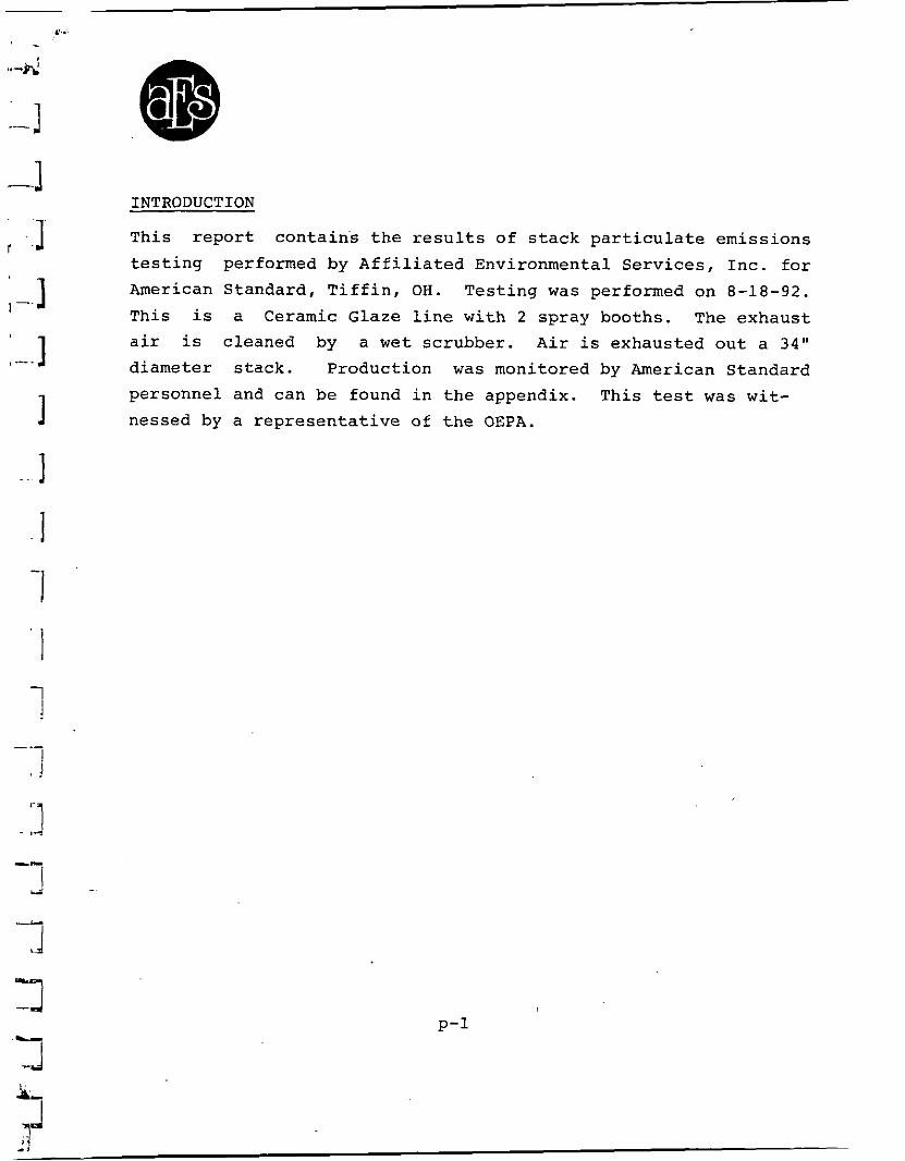
PLANT NAME: American Standard R001
DATE OF TEST: 8-18-92
STACK SAMPLING PARAMETERS
TEST RUN NUMBER 1
MINUTES OF TEST VOLUME OF GAS COLLECTED cubic feet METER CALIBRATION FACTOR Y BAROMETRIC PRESSURE PRESSURE DIFFERENTIAL ACROSS ORIFICE DELTA H METER TEMPERATURE (+460) STACK STATIC PRESSURE (HG) STACK TEMPERATURE (+460) AVERAGE SQUARE ROOT OF VELOCITY HEAD VOLUME OF IMPINGER WATER COLLECTED m 1 WEIGHT OF SILICA COLLECTED gms AREA OF SAMPLING NOZZLE aquare feet PITOT TUBE COEFFICIENT AREA OF STACK square feet CARBON DIOXIDE (DRY FRACTION) CARBON MONOXIDE (DRY FRACTION) OXYGEN (DRY FRACTION) NITROGEN (DRY FRACTION)
STACK PARTICULATE DATA
GAS VOLUME STANDARD CONDITIONS DSCF VOLUUE OF WATER VAPOR cubic feet PERCENT MOISTURE IN STACK GAS DRY GAS MOLECULAR WEIGHT STACK GAS MOLECULAR WEIGHT VELOCITY OF STACK GAS feet per second FLOW RATE OF STACK GAS DSCFH FLOW RATE OF STACK GAS DSCFM ISOKINICITY %
WEIGHT GAIN OF IMPINGERS ag WEIGHT GAIN OF FILTER mg WEIGHT GAIN OF PROBE WASH mg PARTICULATES COLLECTED POUNDS/HOUR PARTICULATES-COLLECTED GRAINS/DSCF PARTICULATES COLLECTED POUNDS/DSCF

@ . . AFFILIATED ENVIRONMENTAL SERVICES, INC. .-- - -
3606 VENICE RD. SANDUSKY, OHIO 44870
PLANT NAME: American Standard R001
DATE OF TEST: 8-18-92
STACK SAMPLING PARAMETERS
TEST RUN NUMBER 2
MINUTES OF TEST VOLUME OF GAS COLLECTED Cubic feet METER CALIBRATION FACTOR Y BAROMETRIC PRESSURE PRESSURE DIFFERENTIAL ACROSS ORIFICE DELTA H METER TEMPERATURE (+460) STACK STATIC PRESSURE (HG) STACK TEMPERATURE (+460) AVERAGE SQUARE ROOT OF VELOCITY HEAD VOLUME OF IMPINGER WATER COLLECTED ml WEIGHT OF SILICA COLLECTED gas AREA OF SAMPLING NOZZLE square feet PITOT TUBE COEFFICIENT AREA OF STACK aquare feet CARBON DIOXIDE (DRY FRACTION) CARBON MONOXIDE (DRY FRACTION) OXYGEN (DRY FRACTION) NITROGEN (DRY FRACTION)
STACK PARTICULATE DATA
GAS VOLUME STANDARD CONDITIONS DSCF VOLUME OF WATER VAPOR cubic feet PERCENT MOISTURE IN STACK GAS DRY GAS MOLECULAR WEIGHT STACK GAS MOLECULAR WEIGHT VELOCITY OF STACK GAS feet per second FLOW RATE OF STACK GAS DSCFH FLOW RATE OF STACK GAS DSCFM ISOKINICITY X WEIGHT GAIN OF IMPINGERS ng WEIGHT GAIN OF FILTER mg WEIGHT GAIN OF PROBE WASH mg PARTICULATES COLLECTED POUNDS/HOUR PARTICULATES COLLECTED GRAINS/DSCF PARTICULATES COLLECTED POUNDSIDSCF
.-
I AFFILIATED ENVIRONMENTAL SERVICES, INC.
3686 VENICE RD. SANDUSKY, OHIO 44870
PLANT NAME: American Standard R881
DATE OF TEST: 8-18-92
STACK SAMPLING PARAMETERS
TEST RUN NUMBER 3
MINUTES OF TEST VOLUME OF GAS COLLECTED cubic feet METER CALIBRATION FACTOR Y ~ -
BAROMETRIC PRESSURE PRESSURE DIFFERENTIAL ACROSS ORIFICE DELTA H METER TEMPERATURE (+460) STACK STATIC PRESSURE (HG)' STACK TEMPERATURE (+468) AVERAGE SQUARE ROOT OF VELOCITY HEAD VOLUME OF IMPINGER WATER COLLECTED rl WEIGHT OF SILICA COLLECTED gme AREA OF SAMPLING NOZZLE square feet PITOT TUBE COEFFICIENT AREA OF STACK square feet CARBON DIOXIDE <DRY FRACTION) CARBON MONOXIDE (DRY FRACTION) OXYGEN (DRY FRACTION) NITROGEN (DRY FRACTION)
STACK PARTICULATE DATA
GAS VOLUME STANDARD CONDITIONS DSCF VOLUME OF WATER VAPOR cubic feet PERCENT MOISTURE IN STACK GAS DRY GAS MOLECULAR WEIGHT STACK GAS MOLECULAR WEIGHT VELOCITY OF STACK GAS feet per second FLOW RATE OF STACK GAS DSCFH FLOW RATE OF STACK GAS DSCFM ISOKINICITY X WEIGHT GAIN OF IMPINGERS ag WEIGHT GAIN OF FILTER mg WEIGHT GAIN OF PROBE WASH ng PARTICULATES COLLECTED POUNDS/HOUR PARTICULATES COLLECTED GRAINSIDSCF PARTICULATES COLLECTED POUNDS/DSCF
- . . I
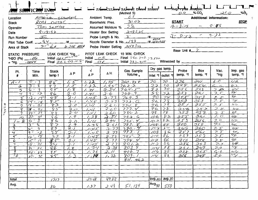
r m . ii ii L: PI,ULMSAAE DM s H b dvg.!+e h m j s s u L-l (Method 5) 0.0 %CO, ~ / . L I 0/00, -
Locatlon , A M I C ~ < , ~ ~ U c ,11+cI(-9/ -c / Ambient Temp. / [> s~ Addltlonal Information:
200i n Stack d T I C < Barometric Pres. 3). u s - S U B I - p.q$ SZPe
Operalor 0 S n f l /sz Assumed Moisture % 3 ,+- 5,'/% Date e- I 5-- 9 z Heater Box Setting 2 q g 2 > < - 3 - r- - 5 - a - "I:,2L Run Number Pmbe Length & No. 3 ' I#
b 4e.=,+ Pitot Tube Coeff. Nozzle Diameter S No. , 1%' I# .ooa/%r
Area of Stadc 3 L , 1 1 ~ , d 6.30g AfFA Pmbe Heater Settina * r Z 9 3 I . .. - - - - .- - - - - Base UnR # 7
STATIC PRESSURE LEAK CHECK "Hg,o ,, PITOT LEAK CHECK 10 MIN. CHECK "H20 (R) initial cYL ~ 5 . ) ~ Initial r- /< Final 7 Lc, s </ J- -7 J - ~ ~
= "Hg. , oo&' Final 0 r L C/> -" ". " Final rr Y Initial 7,s 1 . 7 - Witnessed by
total Avg.
. ,.
i 7 / 7
(/k
-17. vf
/ ,3 7
Y9.82
2. q7 5 . / ; i / a v g . m
AVgtl,o
WI.JD
f50

I I u -4 p*ws& d& s& k : h , L L V ~ v g . yrlle naysis (Method 5) ,7 o O/O CO, -7 / o %O, .
2 cr - Locatlon 9 A S,'Pru&,rt' Ambient Temp. Addltlonal Intormatlon: Stack 2 ~ 1 00 7 Barometric Pres. -*)- G 2 SIBBI
'z-
SIPe T C , ~ 5-2 Assumed Moisture % 3 I?- - i l q o .- Operator /u . 'YO
Date $ - / k - 5 2 Heater Box Setting ~' '- Run Number T Probe Lenglh & No. 5 ' I# 2 - /<:,., / ;A - / O . + ' 1
Plot Tube Coeff. . 9 . . I# Nozzle Diameter & No. - / f 2 I# + -
Area of Stack 35l "d . R Per# - ~5. 30J- Probe Heater Setting ,+/:5 - -4
Base Una # ' J STATIC PRESSURE LEAK CHECK "Hg PlTOT LEAK CHECK 10 MIN. CHECK 'H20 (Ps) ,o(. Initial k , , Initial ct'? Final = "Hg. .ooYL/ Final (4 L-wA A' 5 Final n C Initial Witnessed by

- w . ,u
I 1 Avg. yrie na ysls.
Ld u u (Method 5) 7 . 0 % CO, @i L'I %O, :
57??*d~N' / d m M,&- , Ambient Temp Addltlonal Inlormatlon: Stack ,ZCY~ I ~ U T / L 7 Barometric Pres. 2f) -<I>. SIAm - SIQe
T G ~ S,7 ~7/* Assumed Moisture % '3 %J. ,3 - /o : -5- 5 - //..as- Operator Date ,$-/8- sz Heater Box Setting 5 75
=? I # 7 - //. .-3c <- Run Number Pmbe Length & No. / 2; OCI
Piot Tube Coeff. . %Y I# Nozzle Diameter 8 No. - / 4 I # ? Y " Area of Stack 6 , 3 9 5 Pmbe Heater Setting 3 y 3 ' 2
Base Unit # r / STATIC PRESSURE . LEAK CHECK "Hg PlTOT LEAK CHECK 10 MIN. CHECK
i "H20 (Ps) ,oh Initial cnk c.oms nr '"I Initial u'k' Final I ="Hg. ,oo . /q Final OIL L ,OO%S' I & ' ' Final ((/(I Initial Witnessed by

APPENDIX
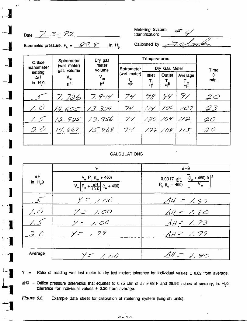
. - Metering System & ' Date 7- 3- 73 Identification: " //
I] Bamrnet"c pressure. P, = ?'? Y in. Ho Calibrated by: -
CALCULATIONS
'-1 Y = Flatii of reading wet test tnetler to dry test meter; tolerance for indivd~al values i 0.02 fmm average.
AtL3 = Orifice pressure differential that equates to 0.75 cfm of air a 68'F and 29.92 inches of mercury, in. H,O: tolerance for individual values k 0.20 from average.
Figure 5.6. Example data sheet for calibration of metering system (English units).

3
1 ... STACK TEMPERATURE SENSOR CALIBRATION DATA FORM
Date 3-57'?? ' 5 5 Thermocouple number 3'
Ambient temperatue 3 OC Barometric pressure 3.?.~q in. H4
c."kw&Reference: mercury-in-glass h(T,+l Calibrator ,,
Reference Source
number specify)
I cc
bat 11
temperature, temperature, OC O C
other
Temperature, difference,
%
Reference thermometer
a~very 30°C (SOOF) for each reference pbint.
b~ype of calibration system used. (ref temp, OC--+ 273) - (test thermom temp, OC + 273)
ref temp, OC + 273 11009.5%.
Thermocouple potentiometer
Quality Assurance Handbook M2-2.10

9 .,
I STACK TEMPERATURE SENSOR CALIBRATION DATA FORM .\ "
7- 3-7 2 ~hermocouple number FAC t f i e - f ~ ~ Boxes
Date
Ambient temperature 23 O C Barometric p ressure 2Y.sf in . Hg
C a l i b r a t o r Reference: mercury-in-glass
Reference point ,
number Source b
( s p e c i f y )
o t h e r
Reference thermometer Temperature,
d i f f e r e n c e , %
very 30°C (50°F) f o r each r e f e r e n c e p o i n t . .
b ~ v v e of c a l i b r a t i o n system used. - r e f temp, 'C + 273) - ( t e s t thermom e m 'C + 2 7 3 ) l
r e f temp, O C + 273 100<1.5%. -
Q u a l i t y Assurance Handbook M2-2.10
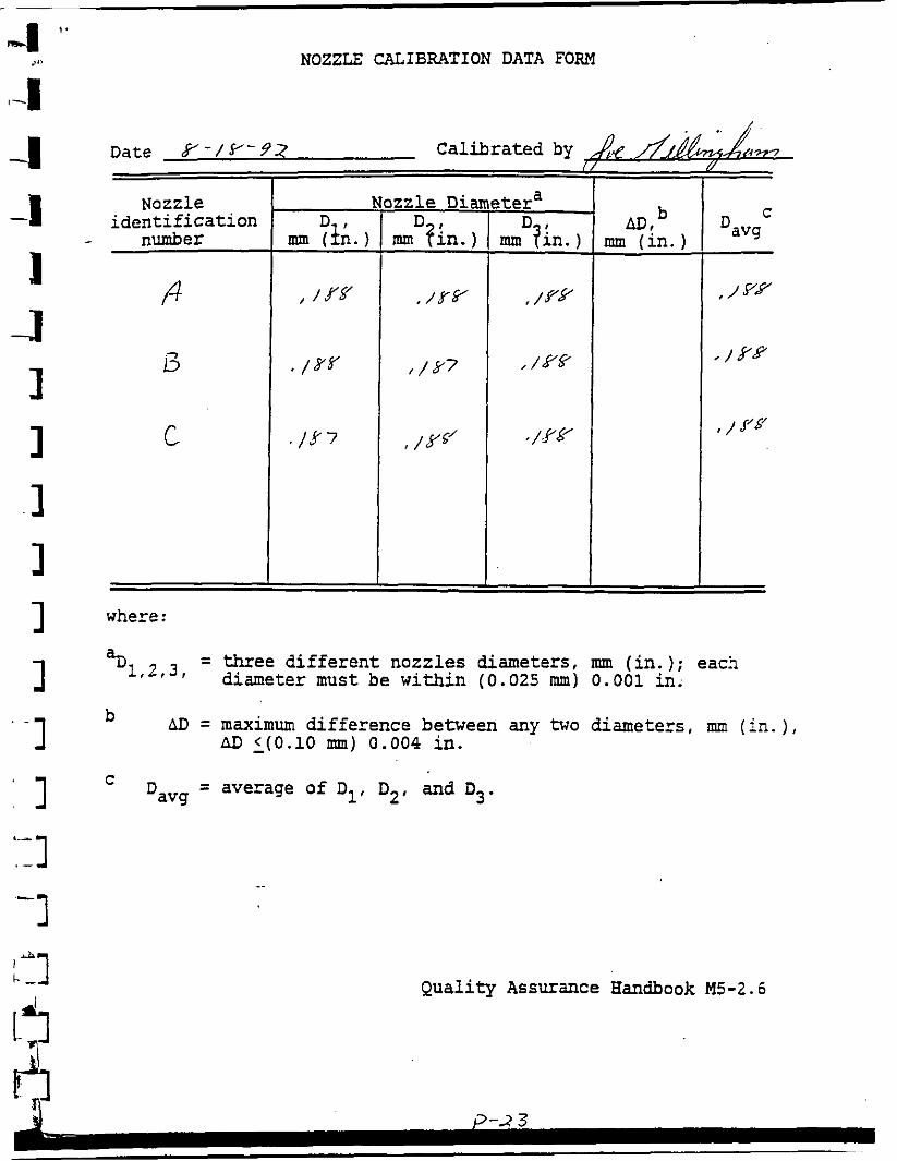
NOZZLE CALIBRATION DATA FORM
where :
Date f - l Y - 9 2 Cal ib ra ted by ,&
a~ = three d i f f e r e n t nozzles diameters, mm ( i n . ); each 1 f 2 ' 3 1 diameter must be w i th in (0.025 mm) 0.001 i n .
b AD = maximum d i f fe rence between any two diameters , mm ( i n . ) ,
AD - <(0.10 mm) 0.004 in .
Nozzle i d e n t i f i c a t i o n
number
f i
13
C
C = average of Dl, D2, and D3. : 1
b AD,
nun ( i n . )
Q u a l i t y Assurance Handbook M5-2.6
#
C
Davg
, / yy
8 / .Yfl
, / J'S'
I /
Nozzle Iliametera D ,
mm ( i n . )
, / ff
, / Xk'
. /f 7
D , ma fin.
. / Y F
/ Y 7
, /YG'
D , mm f i n . )
, /Yfl
, /YY
, /YL'
Qual i ty Assurance Handbook ~ 7 - 2 . 2


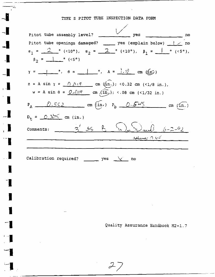
TYPE S PITOT TUBE INSPECTION DATA FORM
I- I P i t o t tube assembly l e v e l ? no
-I P i t o t tube openings damaged? - yes ( e x p l a i n below) V' no
a = ? ( < l o o ) , 1 J 0 - - 7 - --" ( < l o 0 ) , 6, = I O ( < S o ) ,
- - I " ( < s o ) 82 -
2 = s i n Y = 0-03 cm ( i n . ) ; < 0 3 2 cm (<1/8 in. 1, /-
~ = ~ s i n ~ = 0-019 c ; r . 0 8 c m ( < 1 / 3 2 i n . )
- r
t Z * i c cm (k+.jJ D = o . , . , 1 <c
P. Comments : 3 , / a Li~ . m - ! k o . I -cy, /! 2, : ; , - 7 - q ' ?
. - - . ,Uc*m, : n. f J
C a l i b r a t i o n r e m i r e d ? Yes Y' no
Q u a l i t y Assurance Bandbook MZ-1.7
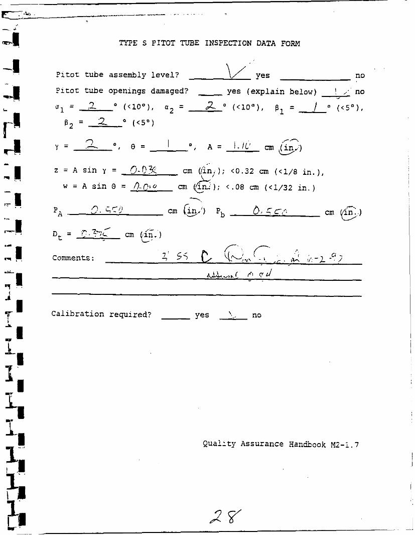
TYPE s PITOT TUBE INSPECTION DATA FORM
/'.
P i t o t tube assembly l e v e l ? I/.'
Yes no
P i t o t tube openings damaged? - yes ( e x p l a i n below) I / no
- ,? - "1 - .- 3 o ( < l o 0 ) , a 2 - - o ( < l o o ) , p, = I n ( < 5 0 ) ,
82 = I ( < 5 O )
z = A s i n y = !-l , ,?I? cm (e.,.); C0.32 cm (<1/8 i n . ) ,
w = A s i n 0 = O,fi14 cm ,(cg ) ; C.08 cm (<1/32 i n . ) L2'
D~ = cm ( i n . )
i k Comments : 3 5s 1' 7 /;: ---"L
C a l i b r a t i o n requi red? yes k' no
Q u a l i t y Assurance aanibook M2-1.7
TYPE S PITOT TUBE INSPECTION DATA FORM
P i t o t tube assembly l e v e l ? no
P i t o t tube openings damaged? yes ( e x p l a i n below) I ," no - u1
= 3 .- " ( < l o o ) , - a2 - a a ( < l o 0 ) , p1 = / " ( < s o ) ,
B2 = 2 (<so)
.. z = ~ s i n y = 5-Qx c m ((hi); '0.32 cm (<1 /8 i n . ) ,
w = A s i n 0 = O - C I O cm en.); /L <.08 an (<1/32 i n . )
-.
P~ n. ccir cm (9.') pb 0, q c c cm E..)
-
C' ... . . .7: 55 '+L:~, + -. h~ , > 7
Ci comments : . ,d !>,-L - , 7
C a l i b r a t i o n requi red? Yes \. . no
Quai i ty Assurance iIan&ook M2-1.7