Embed Size (px)
Citation preview

““Formulation and calculation of Formulation and calculation of isoparametricisoparametric finite element matrixesfinite element matrixes””
--Formulation of structural elements Formulation of structural elements ((plate and general shell elementsplate and general shell elements))
Andres Andres MenaMena (PhD student)(PhD student)Institute of Structural Engineering, ETHInstitute of Structural Engineering, ETH
Date: 13.12.2006Date: 13.12.2006

Plate and general shell elementPlate and general shell element
Shell element definition
τzz = 0 (stress perpendicular to the midsurface)
Plate and general shell elementPlate and general shell element
- Formulation of the plane stress element
Content
- Rotational stiffness perpendicular to the element surface
- Formulation of the plate element
- The general shell element
- The patch test and the incompatible displacement modes
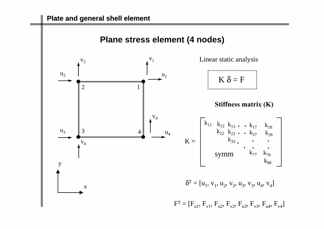
Plate and general shell elementPlate and general shell element
Plane stress element (4 nodes)
4 u4
v4
x
y
u1
v1
12
3
u2
v2
u3
v4
K δ = F
Linear static analysis
K =
k11
..
k77k88
symm
Stiffness matrix (K)
k22
k12
k78
. .k17 k18k27 k28
..
.
...
k33
k13k23
δT = [u1, v1, u2, v2, u3, v3, u4, v4]
FT = [Fu1, Fv1, Fu2, Fv2, Fu3, Fv3, Fu4, Fv4]

Plate and general shell elementPlate and general shell element
Plane stress element (4 nodes)
4 u4
v4
x
y
r
su1
v1
12
3
u2
v2
u3
v4
r = 1, s = 1
-1 ≤ r ≤ 1
-1 ≤ s ≤ 1 u(r,s) = Σ hi (r,s) uii = 1
4
v(r,s) = Σ hi (r,s) vii = 1
4
Displacement and Coordinate Interpolation
h1 = (1+r) (1+s) / 4
h2 = (1-r) (1+s) / 4
h3 = (1-r) (1-s) / 4
h4 = (1+r) (1-s) / 4
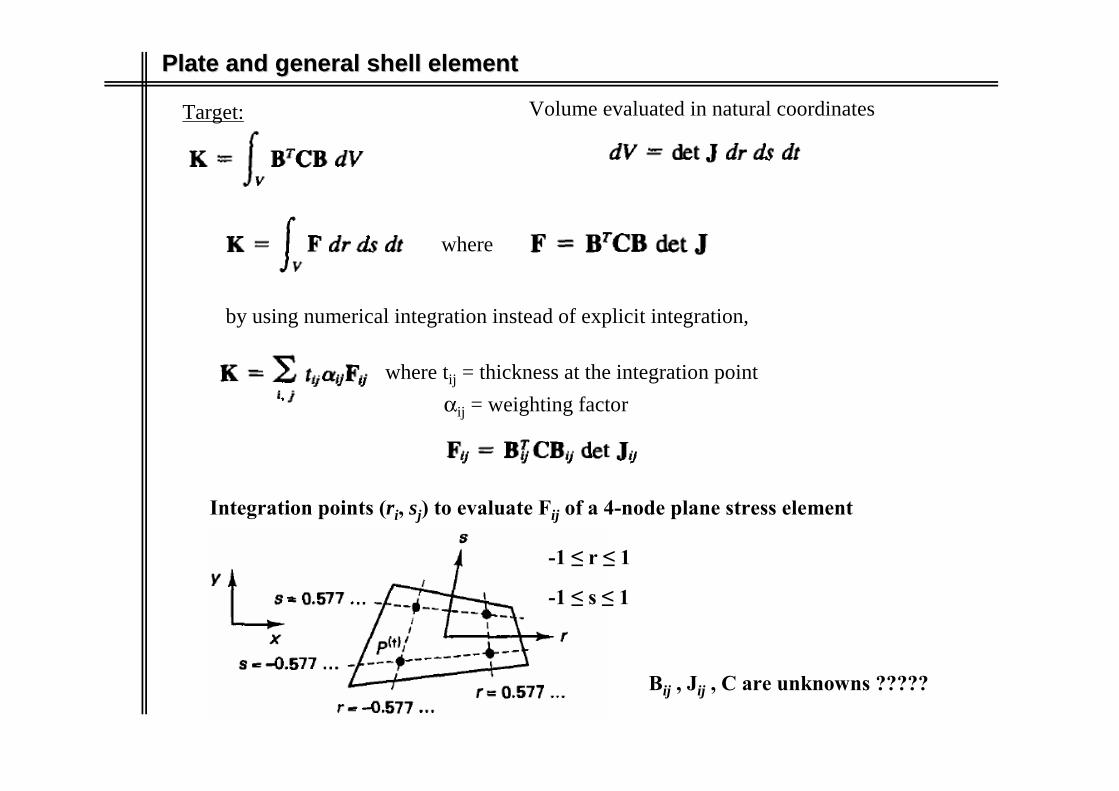
Plate and general shell elementPlate and general shell element
Target:
where
by using numerical integration instead of explicit integration,
where tij = thickness at the integration pointαij = weighting factor
Integration points (ri, sj) to evaluate Fij of a 4-node plane stress element
Bij , Jij , C are unknowns ?????
-1 ≤ r ≤ 1
-1 ≤ s ≤ 1
Volume evaluated in natural coordinates

Plate and general shell elementPlate and general shell element
Matrixes Jij and Bij
Shape functions to calculate the Jacobian (Jij)
x(r,s) = Σ hi (r,s) xii = 1
4
Shape functions to interpolate displacements
u(r,s) = Σ hi (r,s) uii = 1
4

Plate and general shell elementPlate and general shell element
Bij evaluated at the integration points (ri,sj)
= Bij3x8
3x1
*8x1

Plate and general shell elementPlate and general shell element
=
Plane stress and isotropic material
3x8
3x3
3x38x38x8
v1v2
4 u4
v4
u1
12
3
u2
u3
v4
K =
k11
..
k77k88
symm
Stiffness matrix (K)
k22
k12
k78
. .k17 k18k27 k28
..
.
...
k33
k13k23
8x8

Plate and general shell elementPlate and general shell element
Calculation of stress
Strains and stresses are calculated at the integration points
= TT
This example correspond to a 9-node element with 3x3 Gauss points

Plate and general shell elementPlate and general shell element
Plate bending element (4 nodes)
K δ = F
K =
k11
..
k1111k1212
symm
Stiffness matrix (K)
k22
k12
k1112
. .k111 k112k211 k212
..
.
...
k33
k13k23
δT = [w1, θx1, θy1, w2, θx2, θy2, w3, θx3, θy3, w4, θx4, θy4]
FT = [Fz1, Mx1, My1, Fz2, Mx2, My2, Fz3, Mx3, My3, Fz4, Mx4, My4]
y
z
x
4
θy1
w1
1
2
3
θx1
θy2
w2 θx2
w3
θx3
θy3
44
4

Plate and general shell elementPlate and general shell element
-1 ≤ r ≤ 1
-1 ≤ s ≤ 1
w(r,s) = Σ hi (r,s) wii = 1
4
βx(r,s)= -Σ hi (r,s) θyii = 1
4
Displacement, Rotation and Coordinate Interpolation
h1 = (1+r) (1+s) / 4h2 …
Plate bending element (4 nodes)
βy(r,s) = Σ hi (r,s) θxii = 1
4

Plate and general shell elementPlate and general shell element
Area evaluated in natural coordinates
dA = det J dr ds
Bending momentShear force
k (shear correction factor for rectangular cross sections) = 5/6

Plate and general shell elementPlate and general shell element
4
θy1
w1
1
2
3
θx1
θy2
w2 θx2
w3
θx3
θy3
44
4
Fext = K * u12x12
12x13x123x1 2x1 12x12x12 12x1
Bk and Bγ are valuated at the integration points (ri,sj)
12x12 12x3 3x3 3x12 12x2 2x2 2x12
12x112x1
Fext =
Linear shape functions to interpolate area forces
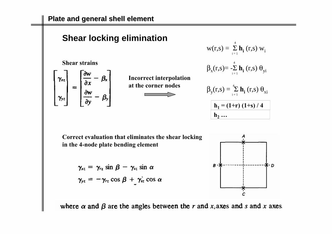
Plate and general shell elementPlate and general shell element
Shear locking elimination
Shear strains
Incorrect interpolation at the corner nodes
Correct evaluation that eliminates the shear locking in the 4-node plate bending element
w(r,s) = Σ hi (r,s) wii = 1
4
βx(r,s)= -Σ hi (r,s) θyii = 1
4
h1 = (1+r) (1+s) / 4h2 …
βy(r,s) = Σ hi (r,s) θxii = 1
4

Plate and general shell elementPlate and general shell element
Shell element
Rotational stiffness perpendicular to the element surface is not defined
Easy solution
One elegant solutions is to add a “real” rotational stiffness for θz,
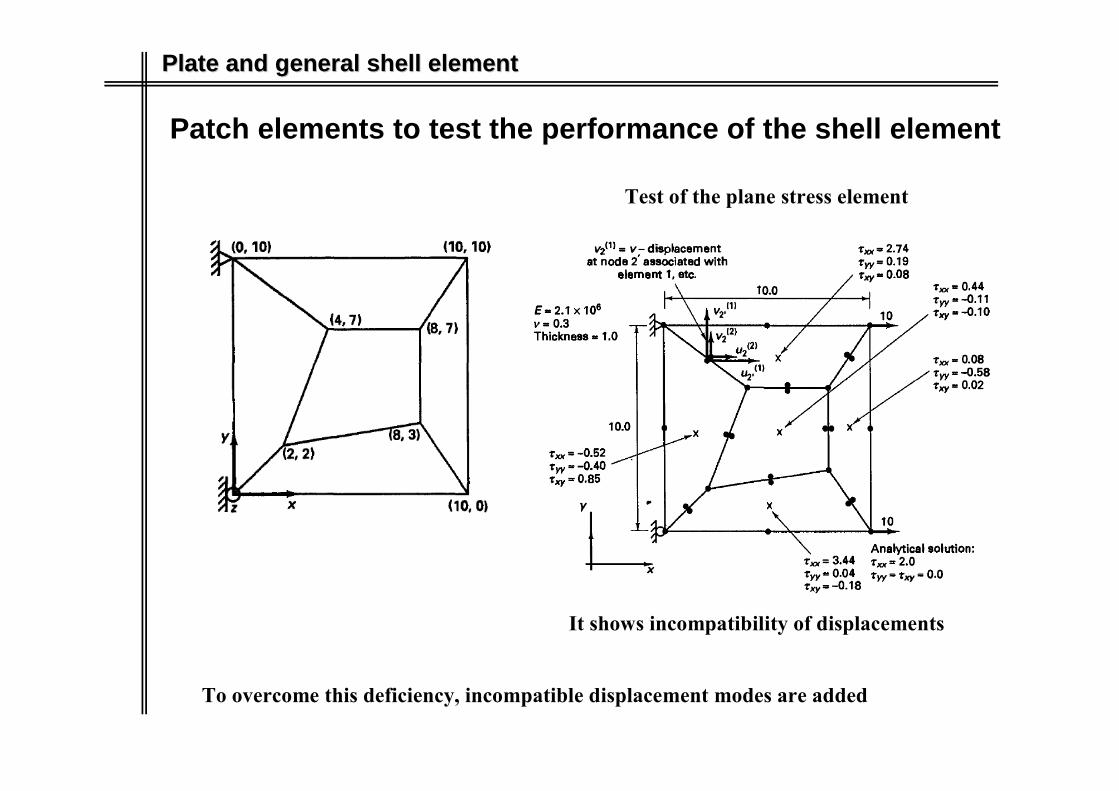
Plate and general shell elementPlate and general shell element
Patch elements to test the performance of the shell element
It shows incompatibility of displacements
To overcome this deficiency, incompatible displacement modes are added
Test of the plane stress element

Plate and general shell elementPlate and general shell element
Incompatible displacement modes
Correction of the incompatible strain-displacement matrixStiffness matrix (K)
12x12
12x1 12x1
Stiffness matrix (8x8) is obtained by applying static condensation(kCC – kCI kII
-1 kIC) u = R8x8 8x1 8x1

Plate and general shell elementPlate and general shell element
Higher order patch tests
For the plane stress element
For the plate bending element

Plate and general shell elementPlate and general shell element
General Shell element
Analysis of complex shell geometries
r = 1, s = 1
-1 ≤ r ≤ 1
-1 ≤ s ≤ 1
-1 ≤ t ≤ 1

Plate and general shell elementPlate and general shell element
General Shell element
Coordinate interpolation
r = 1, s = 1
x
y
z
in plane yz
-1 ≤ t ≤ 1
x = x1
y = y1 + 0.5 * 0.8√0.2 * (-1/√2)
For t = 1
z = z1 + 0.5 * 0.8√0.2 * (1/√2)
x = x1
y = y1 + -0.5 * 0.8√0.2 * (-1/√2)
For t = -1
z = z1 + -0.5 * 0.8√0.2 * (1/√2)

Plate and general shell elementPlate and general shell element
General Shell element
Displacement interpolation
Strain – displacement matrix B(r,s,t)
B(r,s,t)

Plate and general shell elementPlate and general shell element
General Shell element
Stress-strain law

Plate and general shell elementPlate and general shell element
General Shell element
Shear locking
9-node shell element

Plate and general shell elementPlate and general shell element
Boundary conditions
Solid element Shell element
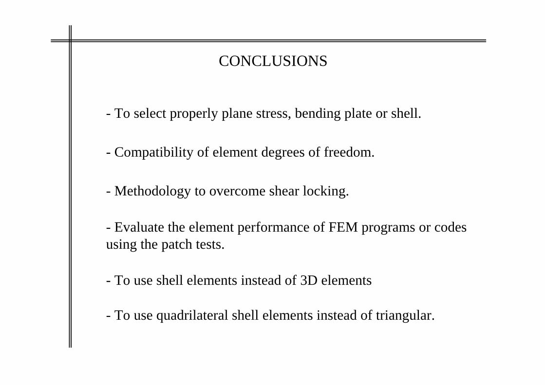
CONCLUSIONS
- Evaluate the element performance of FEM programs or codes using the patch tests.
- Methodology to overcome shear locking.
- To use shell elements instead of 3D elements
- To use quadrilateral shell elements instead of triangular.
- Compatibility of element degrees of freedom.
- To select properly plane stress, bending plate or shell.

THANK YOU


![Research Article Finite Element Formulation for Stability ...isoparametric formulation, displacement and rotation elds are assumed dependently with the same order [ ]. Based ... In](https://img.pdfslide.us/doc/110x75/60a51997bcbce27c2e343007/research-article-finite-element-formulation-for-stability-isoparametric-formulation.jpg)