Embed Size (px)
Citation preview
1
““Automatic Synthesis of Automatic Synthesis of a Planar Linkage Mechanisma Planar Linkage Mechanism””
Yoon Young Kim
Seoul National University
2
Our Goal: Automatic Mechanism Synthesis?
?
2
3
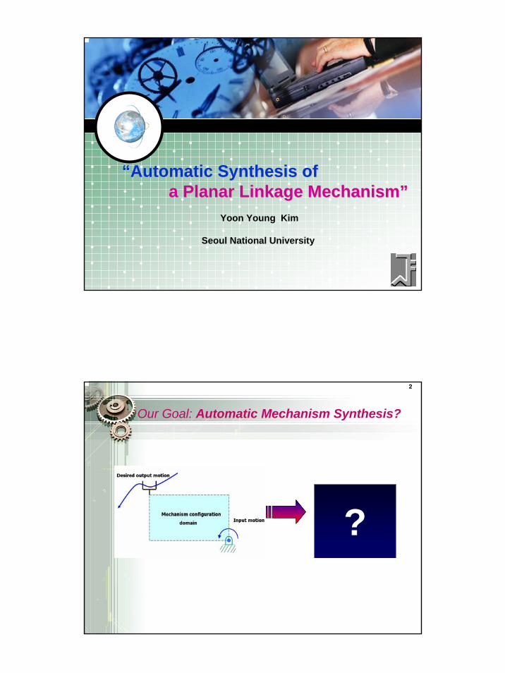
Research MotivationResearch Motivation…………
More Use of Robots or artificial life-forms Motion-generating mechanisms become also important.
Optimization Methodology Can Be a Critical Design Tool.
Space Robot at MIT Binary Manipulatorat Johns Hopkins
Arrow Model at Brandeis Univ. Binary Manipulator
at SNU
4
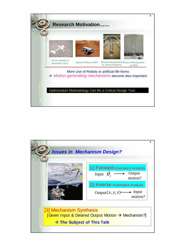
Issues in Mechanism Design?
1θ
2θ
3θ
( , , )x y z
[1] Forward Kinematics Analysis
Input iθ Output motion?
[2] Inverse Kinematics Analysis
Output( , , )x y z Input motion?
[3] Mechanism Synthesis [Given Input & Desired Output Motion Mechanism?]
The Subject of This Talk
3
5
Related Research
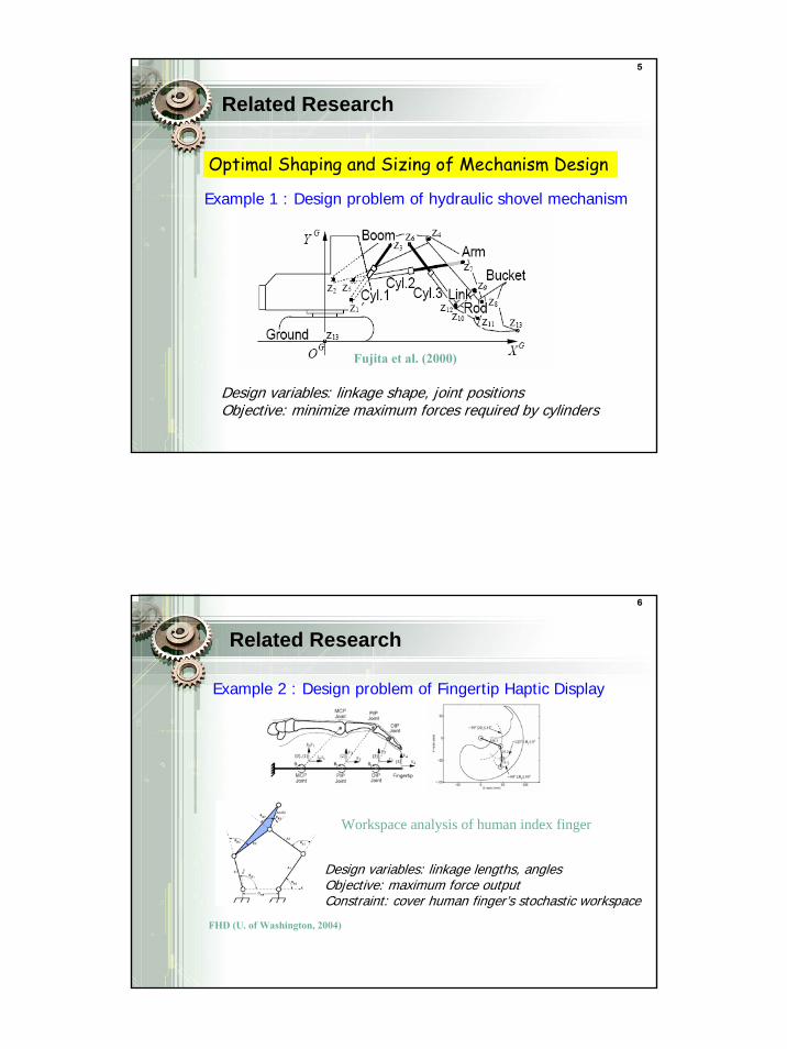
Design variables: linkage shape, joint positionsObjective: minimize maximum forces required by cylinders
Optimal Shaping and Sizing of Mechanism Design
Fujita et al. (2000)
Example 1 : Design problem of hydraulic shovel mechanism
6
Related Research
Design variables: linkage lengths, anglesObjective: maximum force outputConstraint: cover human finger’s stochastic workspace
Workspace analysis of human index finger
Example 2 : Design problem of Fingertip Haptic Display
FHD (U. of Washington, 2004)
4
7
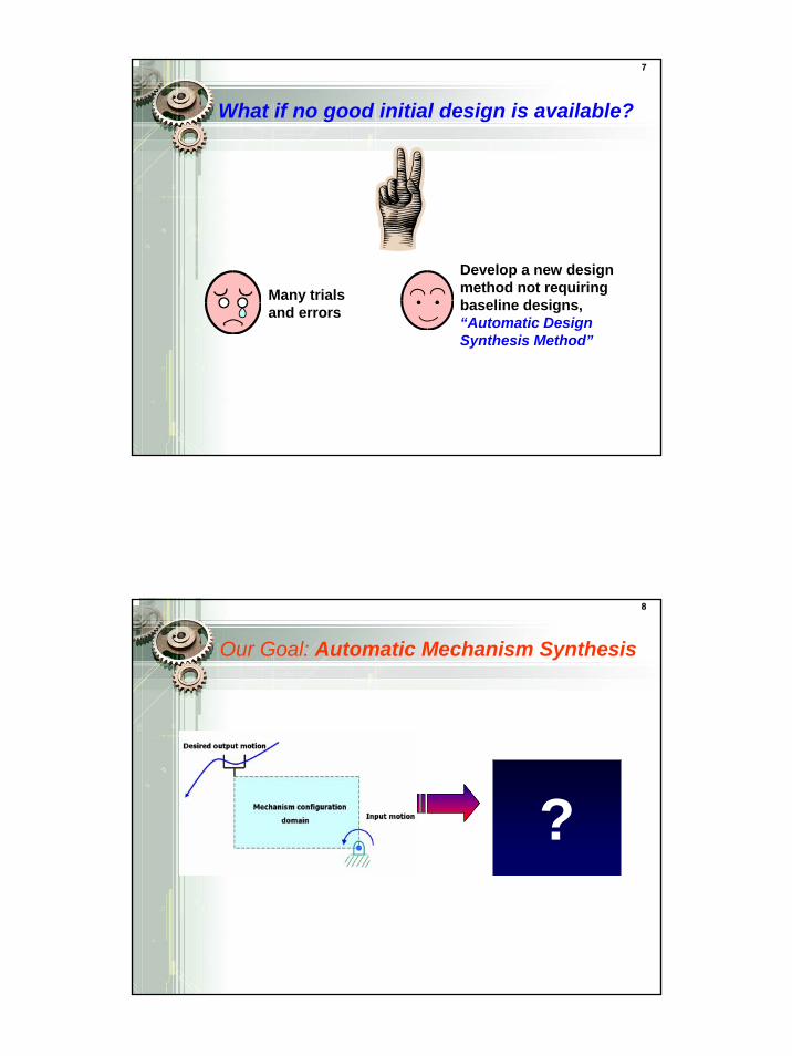
What if no good initial design is available?
Develop a new design method not requiring baseline designs, “Automatic Design Synthesis Method”
Many trials and errors
8
Our Goal: Automatic Mechanism Synthesis
?
5
9
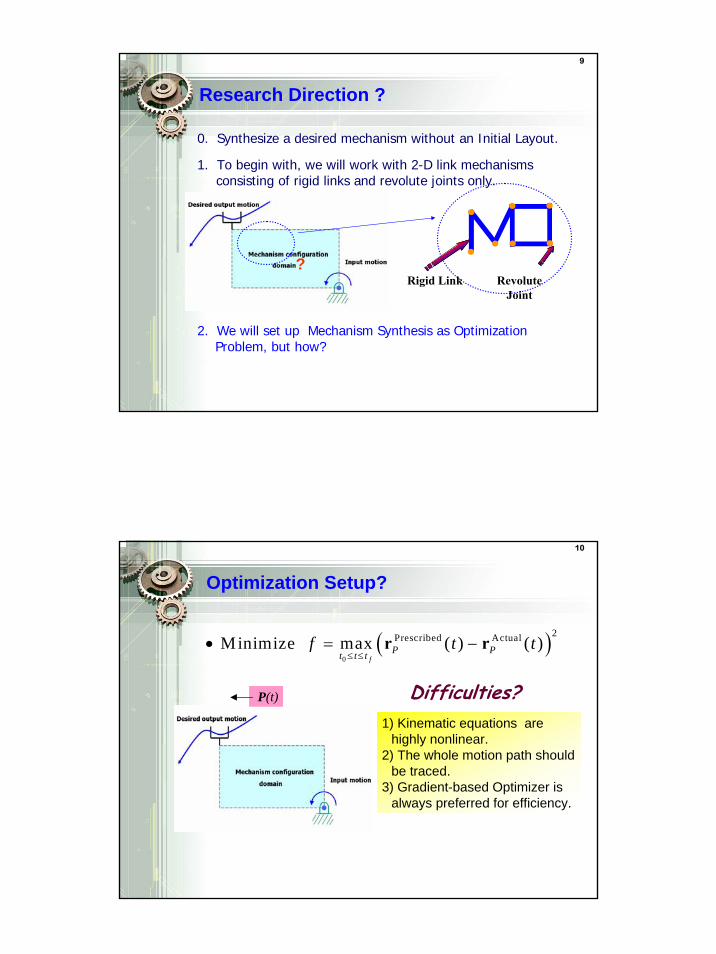
Research Direction ?
0. Synthesize a desired mechanism without an Initial Layout.
?Rigid Link Revolute
Joint
1. To begin with, we will work with 2-D link mechanisms consisting of rigid links and revolute joints only.
2. We will set up Mechanism Synthesis as Optimization Problem, but how?
10
Optimization Setup?
( )0
2Prescribed Actual Minimize max ( ) ( )f
P Pt t tf t t
≤ ≤• = −r r
P(t)
1) Kinematic equations are highly nonlinear.
2) The whole motion path should be traced.
3) Gradient-based Optimizer is always preferred for efficiency.
Difficulties?
6
11
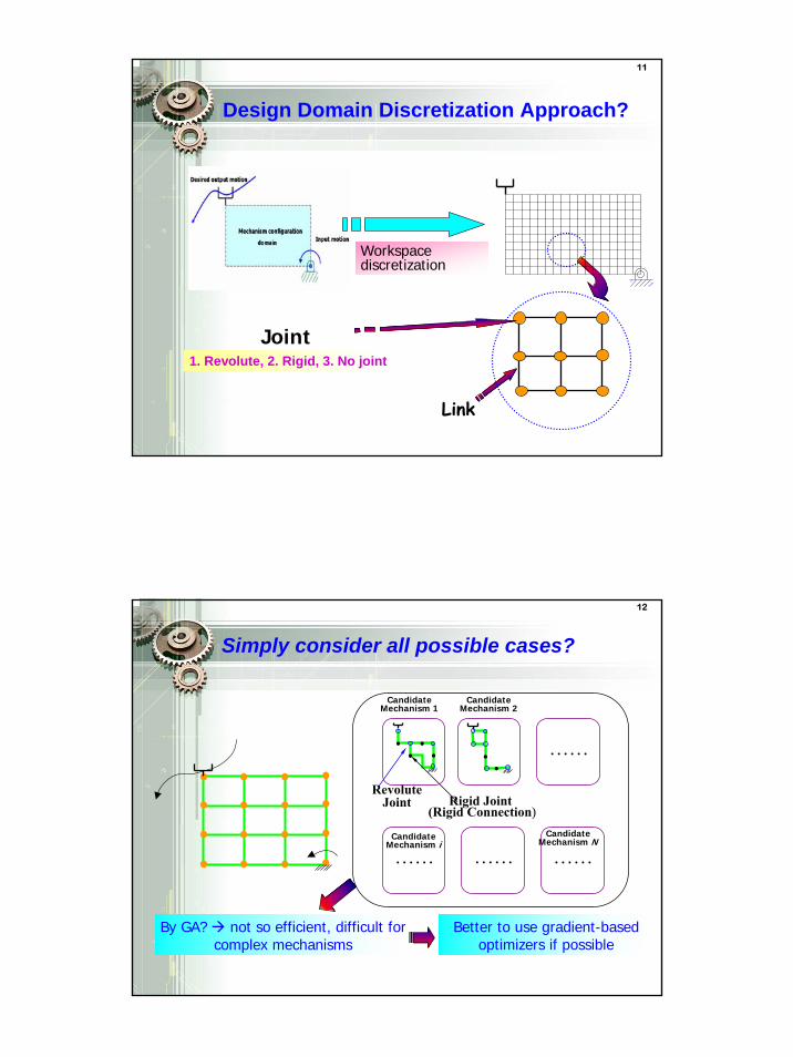
Design Domain Discretization Approach?
Workspace discretization
Link
Joint1. Revolute, 2. Rigid, 3. No joint
12
Simply consider all possible cases?
Revolute Joint Rigid Joint
(Rigid Connection)
Candidate Mechanism 1
. . . . . .
. . . . . . . . . . . . . . . . . .
Candidate Mechanism 2
Candidate Mechanism i
Candidate Mechanism N
By GA? not so efficient, difficult for complex mechanisms
Better to use gradient-based optimizers if possible
7
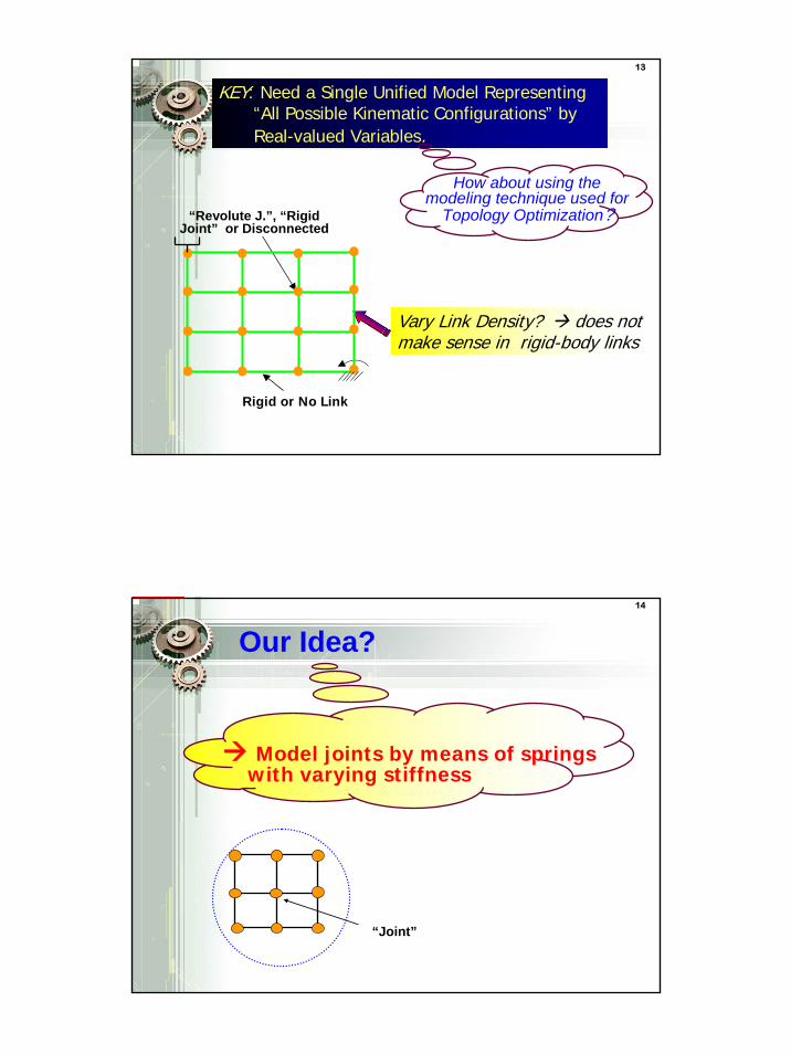
13
KEY: Need a Single Unified Model Representing “All Possible Kinematic Configurations” by Real-valued Variables.
Vary Link Density? does not make sense in rigid-body links
How about using the modeling technique used for
Topology Optimization?
Rigid or No Link
“Revolute J.”, “Rigid Joint” or Disconnected
14
Model joints by means of springs with varying stiffness
Our Idea?
“Joint”
8
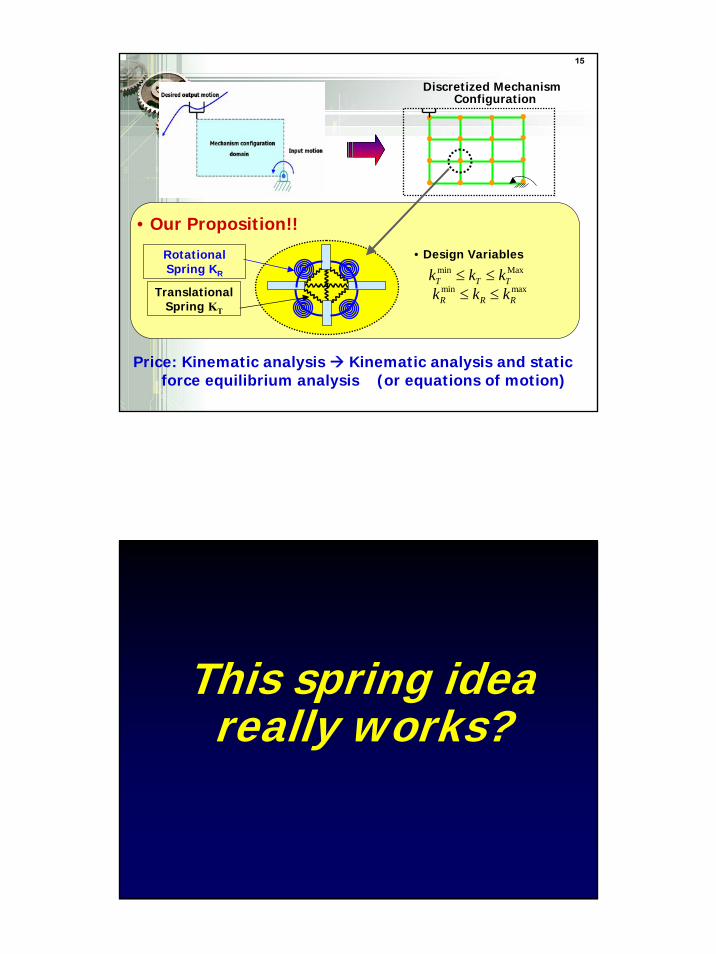
15
Discretized Mechanism Configuration
Translational Spring KT
Rotational Spring KR
• Design Variables min MaxT T Tk k k≤ ≤
min maxR R Rk k k≤ ≤
Price: Kinematic analysis Kinematic analysis and static force equilibrium analysis (or equations of motion)
• Our Proposition!!
16
This spring idea really works?
9
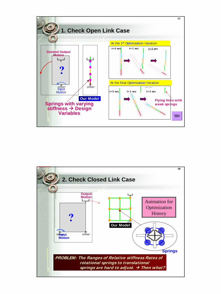
17
1. Check Open Link Case1. Check Open Link Case
?Input
Motion
Desired Output Motion
Springs with varying stiffness Design
Variables
Our Model
t=0 sec t=1 sec t=2 sec
t=0 sec t=1 sec t=2 sec
Flying links with weak springs
At the 1st Optimization Iteration
At the final Optimization Iteration
18
2. Check Closed Link Case
Known Solution (Mechanism)
Springs
Our Model?
Input Motion
Output Motion
PROBLEM: The Ranges of Relative stiffness Rates of rotational springs to translational springs are hard to adjust. Then what?
Animation for Optimization
History
10
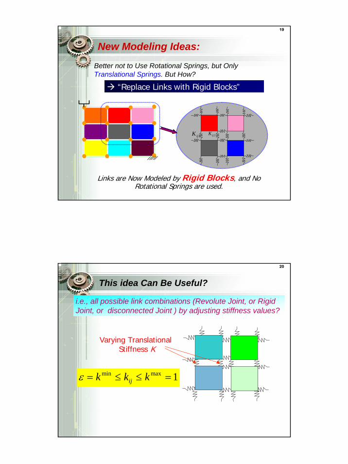
19
New Modeling Ideas:
“Replace Links with Rigid Blocks”
Links are Now Modeled by Rigid Blocks, and No Rotational Springs are used.
1ijK 2ijK
Better not to Use Rotational Springs, but Only Translational Springs. But How?
20
This idea Can Be Useful?
i.e., all possible link combinations (Revolute Joint, or Rigid Joint, or disconnected Joint ) by adjusting stiffness values?
min max 1ijk k kε = ≤ ≤ =
Varying Translational Stiffness K
11
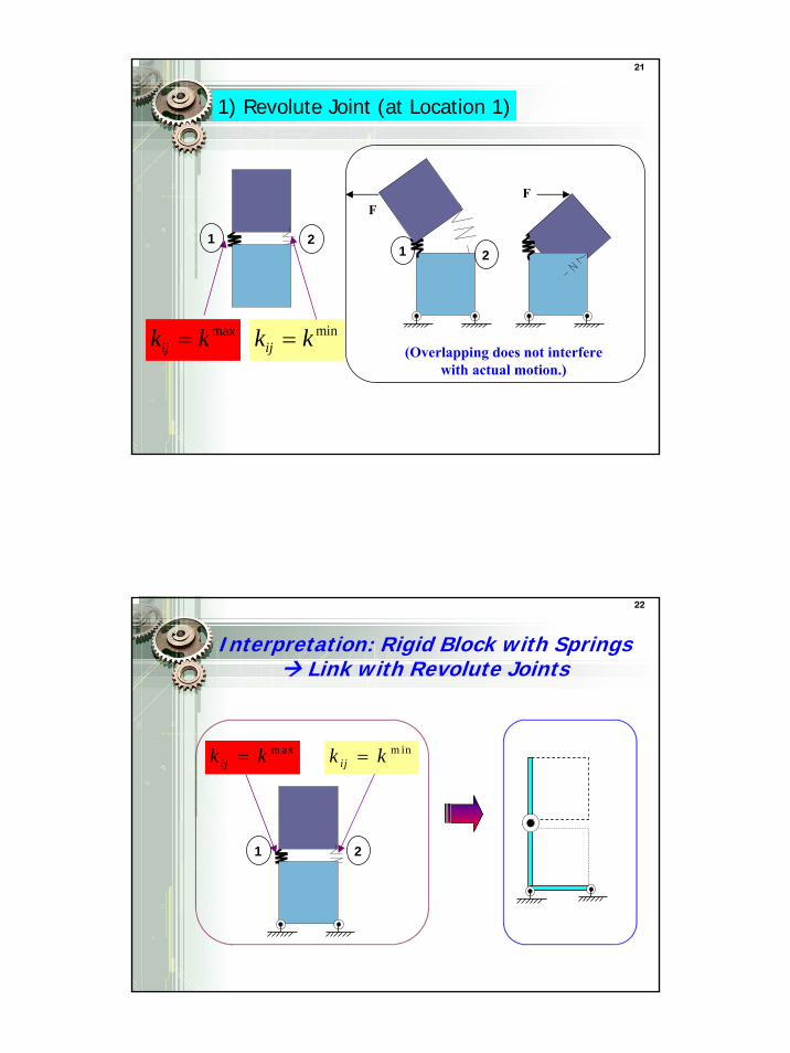
21
1) Revolute Joint (at Location 1)
maxijk k= min
ijk k=
1 2
F
(Overlapping does not interfere with actual motion.)
F
1 2
22
m inijk k=
1 2
m axijk k=
Interpretation: Rigid Block with Springs Link with Revolute Joints
12
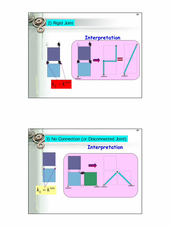
23
2) Rigid Joint
Interpretation
maxijk k=
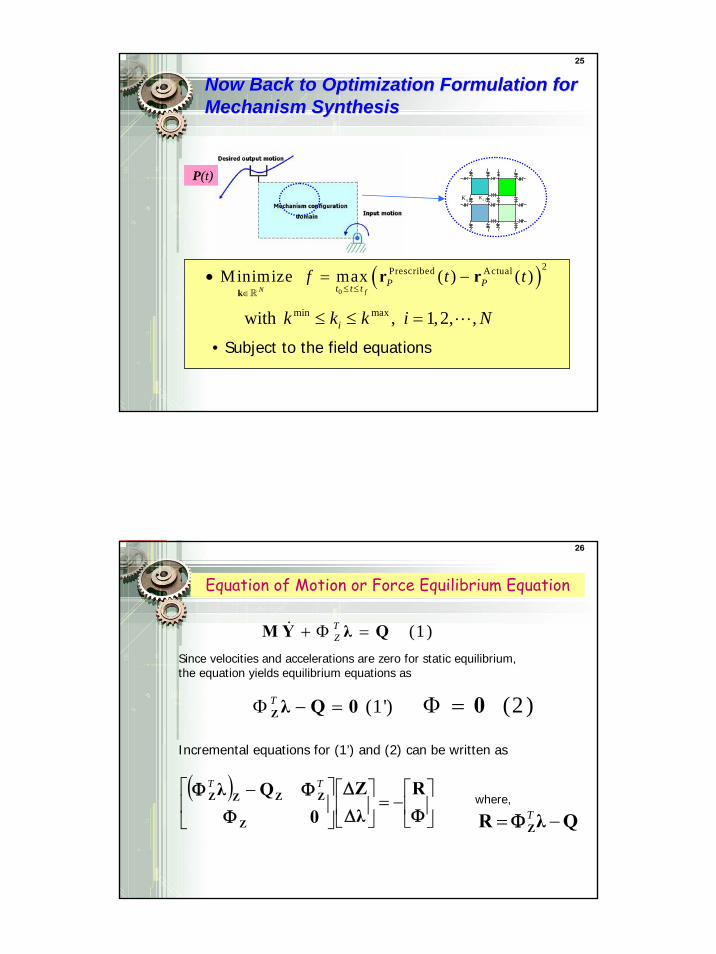
24
3) No Connection (or Disconnected Joint)
minijk k=
Interpretation
13
25
Now Back to Optimization Formulation for Now Back to Optimization Formulation for Mechanism SynthesisMechanism Synthesis
P(t)1ijK 2ijK
min maxwith , 1,2, ,ik k k i N≤ ≤ =
( )0
2Prescribed Actual Minimize max ( ) ( )N f
P Pt t tf t t
≤ ≤∈• = −
kr r
• Subject to the field equations
26
Equation of Motion or Force Equilibrium Equation
(1 )TZ+ Φ =M Y λ Q
Since velocities and accelerations are zero for static equilibrium, the equation yields equilibrium equations as
(1')TΦ − =Zλ Q 0 (2 )Φ = 0
Incremental equations for (1’) and (2) can be written as
( )⎥⎦
⎤⎢⎣
⎡−=⎥
⎦
⎤⎢⎣
⎡⎥⎦
⎤⎢⎣
⎡ −ΦΔ
Δ
ΦΦΦ R
λZ
0Qλ
Z
ZZZZTT
QλR Z −= TΦwhere,
14
27
Mechanism Synthesis : Case Study
Input Motion
?oMotion 2:-20 Time×
oMotion 1:30 Time×
Objective: Minimize
Number of Design Variables: 19(open), 8(closed)( )
0
2Prescribed Actualmax ( ) ( )f
P Pt t tt t
≤ ≤−r r
Output Motion
Input Motion ?
oMotion :30 Time×
Output Motion
Open linkage
Closed linkage
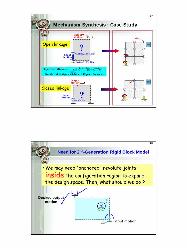
28
Need for 2nd-Generation Rigid Block Model
•We may need “anchored” revolute joints inside the configuration region to expand the design space. Then, what should we do ?
Input motion
Desired output motion ?
15
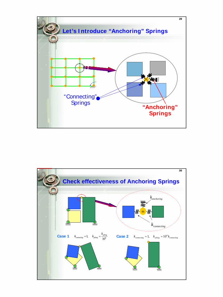
29
m
“Connecting”Springs
Let’s Introduce “Anchoring” Springs
“Anchoring”Springs
30
Check effectiveness of Anchoring Springs
anchoringk
connectingk
m
Case 1 41,10piling
connecting piling
kk k= = Case 2 41, 10connecting piling connectingk k k= =
16
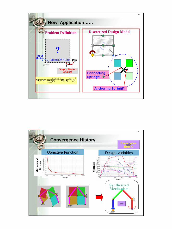
31
Now, Application……
Input Motion
?oMotion :30 Time×
( )0
2Prescribed ActualMinimize max ( ) ( )f
P Pt t tt t
≤ ≤−r r
Problem Definition
P(t)
Output Motion (click!) Connecting
Springs:
Anchoring Springs:
Discretized Design Model
32
Convergence History
Max
imum
of
Dis
tanc
e
Stiff
ness
Objective Function Design variables
Convergence History
Synthesized Mechanism
17
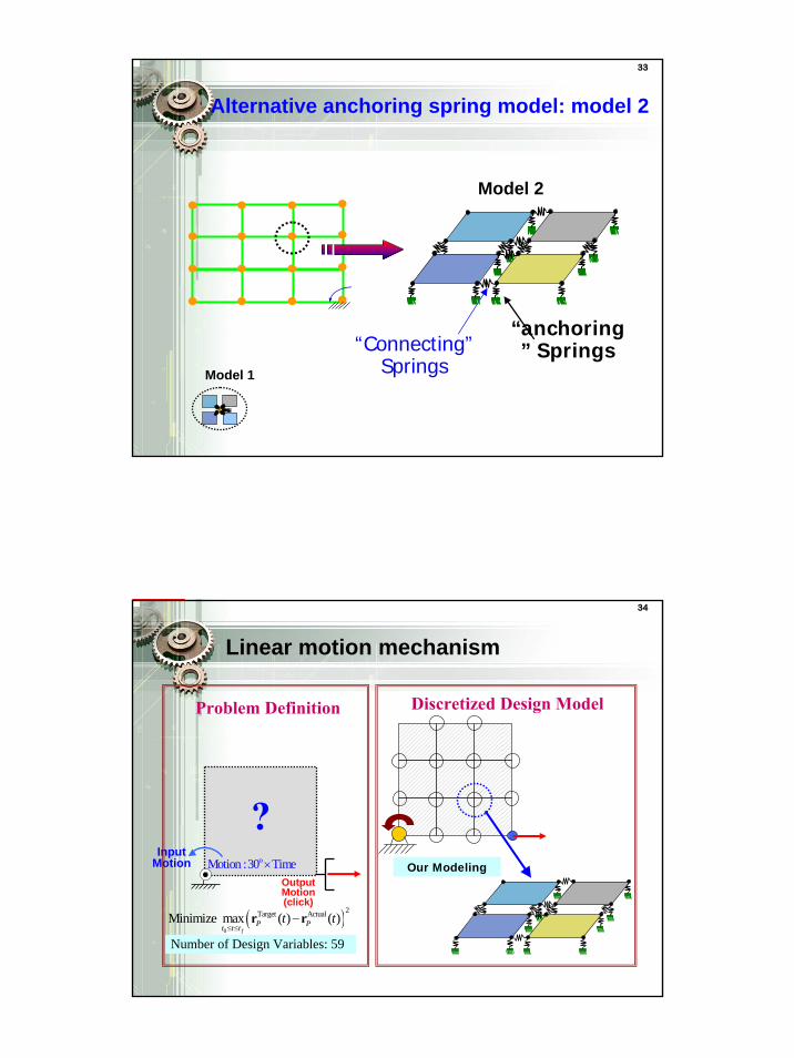
33
Alternative anchoring spring model: model 2
“Connecting”Springs
“anchoring” Springs
m
Model 1
Model 2
34
Linear motion mechanism
Number of Design Variables: 59
Problem Definition
Input Motion
( )0
2Target ActualMinimize max ( ) ( )f
P Pt t tt t
≤ ≤−r r
?oMotion :30 Time×
Output Motion (click)
Discretized Design Model
Our Modeling
18
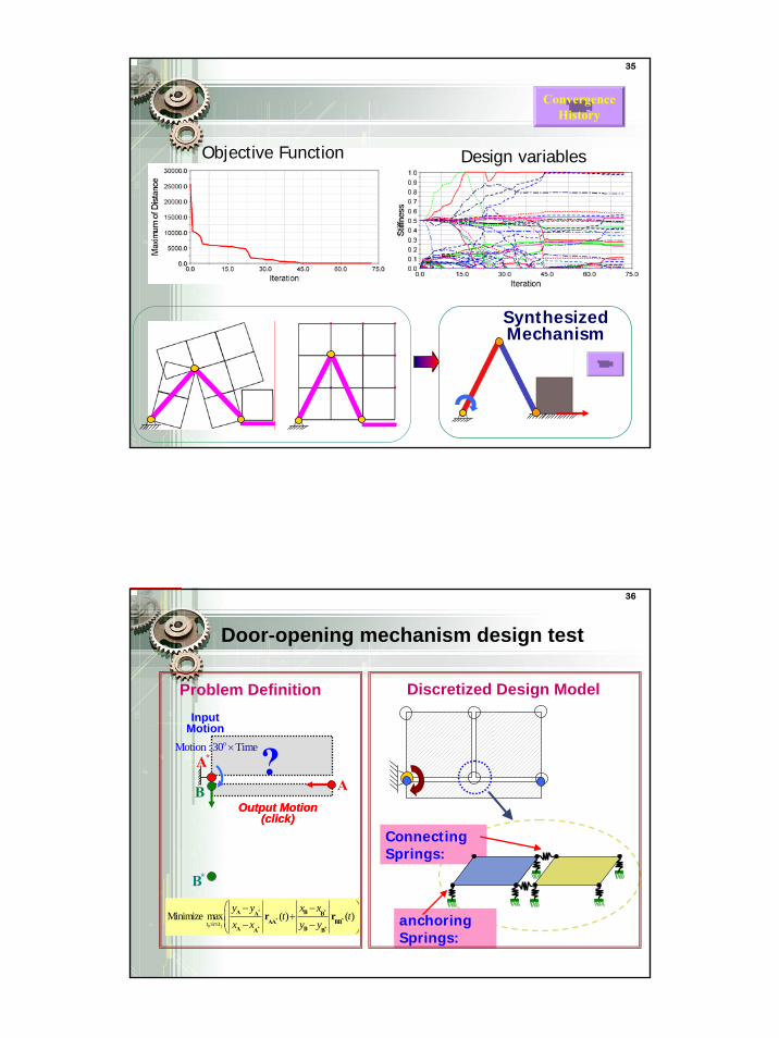
35
Objective Function Design variables
Convergence History
Synthesized Mechanism
36
Door-opening mechanism design test
Problem Definition
Output Motion (click)
0
Minimize max ( ) ( )ft t t
y y x xt t
x x y y≤ ≤
⎛ ⎞− −+⎜ ⎟
⎜ ⎟− −⎝ ⎠
* *
* *
* *
A BA BAA BB
A BA B
r r
Connecting Springs:
anchoring Springs:
Discretized Design Model
?oMotion :30 Time×
Input Motion
Output Motion (click)
*AA
*B
B
19
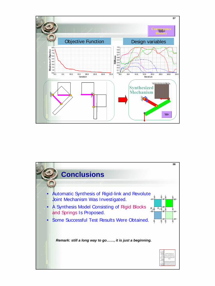
37
Objective Function Design variables
Convergence History
Synthesized Mechanism
38
ConclusionsConclusions
• Automatic Synthesis of Rigid-link and Revolute Joint Mechanism Was Investigated.
• A Synthesis Model Consisting of Rigid Blocks and Springs Is Proposed.
• Some Successful Test Results Were Obtained.
Remark: still a long way to go……, it is just a beginning.
1ijK 2ijK
20
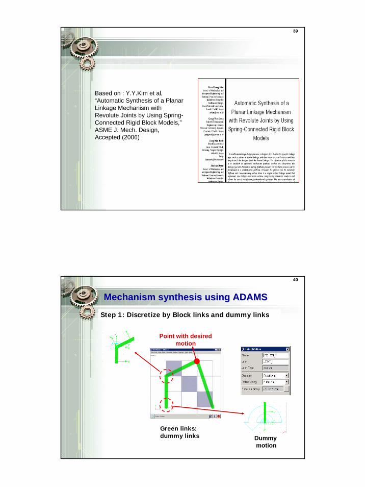
39
Based on : Y.Y.Kim et al, “Automatic Synthesis of a Planar Linkage Mechanism with Revolute Joints by Using Spring-Connected Rigid Block Models,”ASME J. Mech. Design, Accepted (2006)
40
Mechanism synthesis using ADAMS Mechanism synthesis using ADAMS
Step 1: Discretize by Block links and dummy links
Green links: dummy links Dummy
motion
Point with desired motion
21
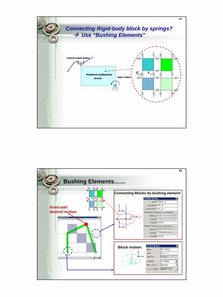
41
1ijK 2ijK
Connecting Rigid-body block by springs? Use “Bushing Elements”
42
Block motion
Point with desired motion
Connecting Blocks by bushing element
Bushing ElementsBushing Elements…………
1ijK 2ijK
22
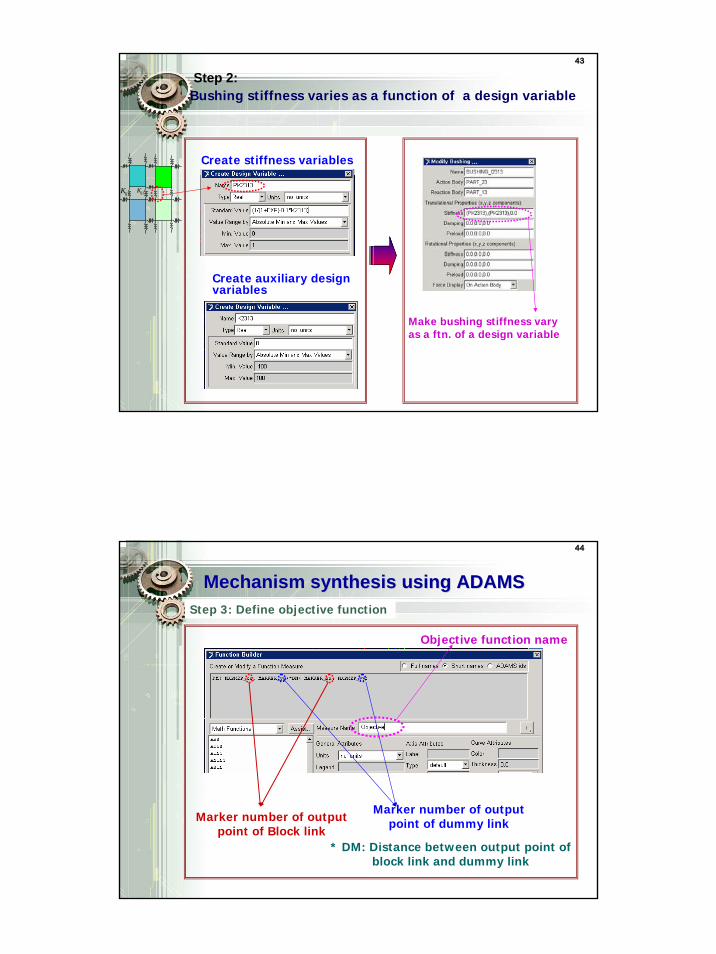
43
Bushing stiffness varies as a function of a design variable
Create stiffness variables
Create auxiliary design variables
Make bushing stiffness vary as a ftn. of a design variable
Step 2:
1ijK 2ijK
44
Mechanism synthesis using ADAMS Mechanism synthesis using ADAMS Step 3: Define objective function
Marker number of output point of Block link
Marker number of output point of dummy link
Objective function name
* DM: Distance between output point of block link and dummy link
23
45
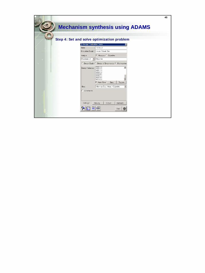
Mechanism synthesis using ADAMS Mechanism synthesis using ADAMS
Step 4: Set and solve optimization problem


![DESIGN OPTIMIZATION OF A PRISMATIC-REVOLUTE-REVOLUTE … · the utility of a hand that combines prismatic and revolute joints in series in each finger [36]. Building upon these results,](https://img.pdfslide.us/doc/110x75/5f827b97758214192765ee25/design-optimization-of-a-prismatic-revolute-revolute-the-utility-of-a-hand-that.jpg)