Embed Size (px)
DESCRIPTION
Â
Citation preview
AO1
Geoffrey Goerling (698748)
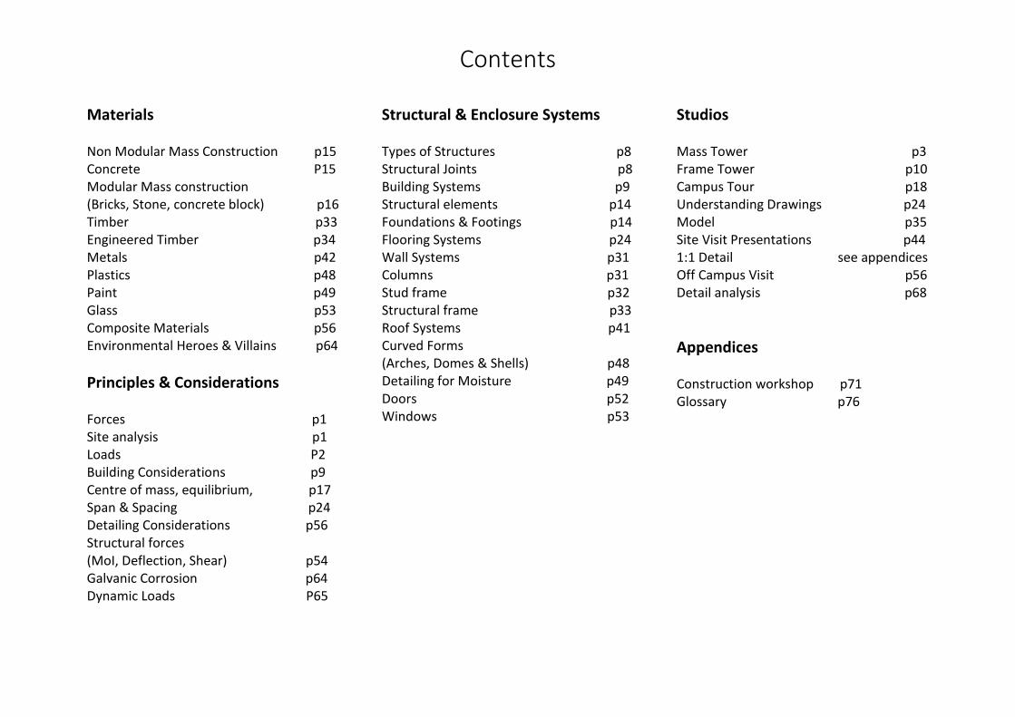
Contents
Materials Non Modular Mass Construction p15 Concrete P15 Modular Mass construction (Bricks, Stone, concrete block) p16 Timber p33 Engineered Timber p34 Metals p42 Plastics p48 Paint p49 Glass p53 Composite Materials p56 Environmental Heroes & Villains p64
Principles & Considerations Forces p1 Site analysis p1 Loads P2 Building Considerations p9 Centre of mass, equilibrium, p17 Span & Spacing p24 Detailing Considerations p56 Structural forces (MoI, Deflection, Shear) p54 Galvanic Corrosion p64 Dynamic Loads P65
Structural & Enclosure Systems Types of Structures p8 Structural Joints p8 Building Systems p9 Structural elements p14 Foundations & Footings p14 Flooring Systems p24 Wall Systems p31 Columns p31 Stud frame p32 Structural frame p33 Roof Systems p41 Curved Forms (Arches, Domes & Shells) p48 Detailing for Moisture p49 Doors p52 Windows p53
Studios Mass Tower p3 Frame Tower p10 Campus Tour p18 Understanding Drawings p24 Model p35 Site Visit Presentations p44 1:1 Detail see appendices Off Campus Visit p56 Detail analysis p68
Appendices Construction workshop p71 Glossary p76

Page | 1
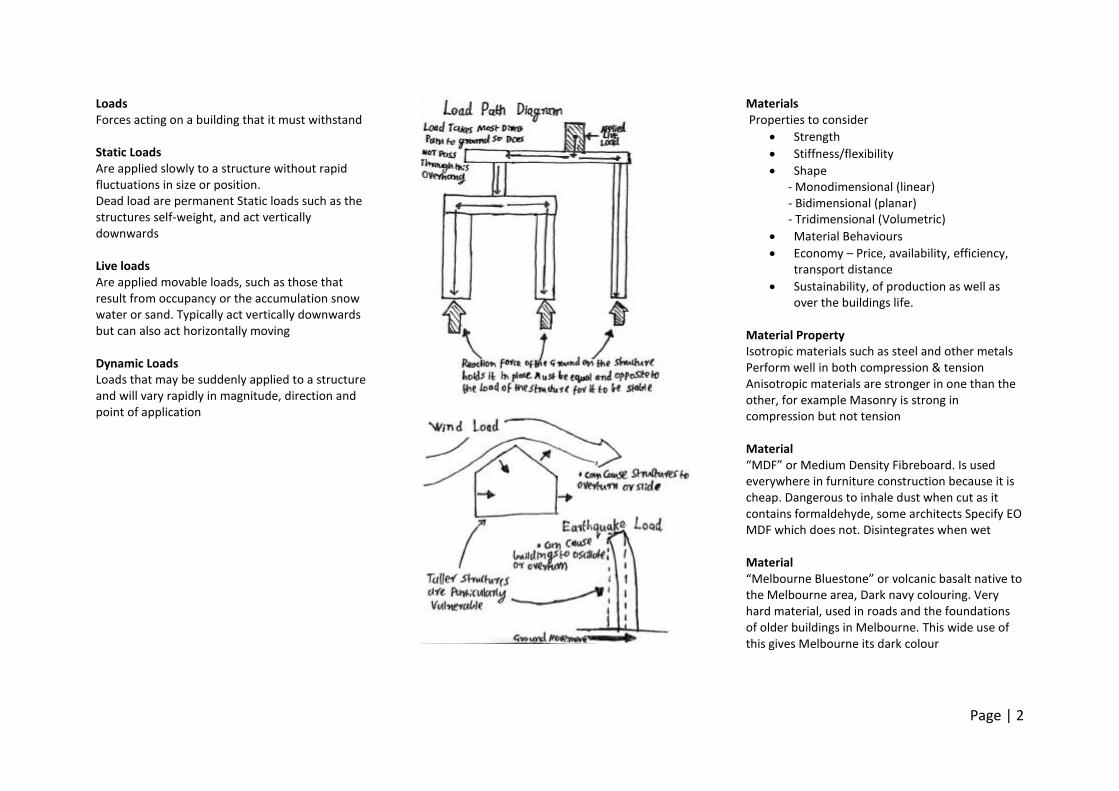
Forces “A force is any influence that produces a change in the shape or movement of a body” (Ching Building Construction illustrated 4th ed 2.11) forces are vector quantities represented by arrows whose orientation represents the direction of the force and size the magnitude. Collinear forces Occur along the same line of action. The resultant force is the algebraic sum of the component forces. Concurrent forces Have lines of action that intersect at a single point. Their effect is equal to their vector sum. This can be found by resolving the vectors into their horizontal and vertical components or adding the forces graphically ‘head to tail’ A Moment is a force that causes a body to rotate about a point. Similarly a couple is a pair of parallel forces acting in opposite directions but along different lines that cause rotation. Buildings can be overturned by lateral loads above a buildings centre if they are not counterbalanced by the restoring moment of the structures dead weight
Site Analysis take into account
Area & shape of site defined by its legal boundaries
Area required for the building, any landscaping or future development
Topography, soil conditions, drainage patterns and water table depth.
Vegetation, waterways or heritage features that should be preserved
Climatic conditions including path of the sun in various seasons, prevailing wind direction etc.
Availability and location of on-site of utilities such as water, phone lines & electricity.
access to roads & how to circulate foot and vehicle traffic on site
context of the site as part of a larger area, eg character of the neighbourhood, sources of noise or congestion, desirable or undesirable view
Page | 2
Loads Forces acting on a building that it must withstand Static Loads Are applied slowly to a structure without rapid fluctuations in size or position. Dead load are permanent Static loads such as the structures self-weight, and act vertically downwards Live loads Are applied movable loads, such as those that result from occupancy or the accumulation snow water or sand. Typically act vertically downwards but can also act horizontally moving Dynamic Loads Loads that may be suddenly applied to a structure and will vary rapidly in magnitude, direction and point of application
Materials Properties to consider
Strength
Stiffness/flexibility
Shape - Monodimensional (linear)
- Bidimensional (planar) - Tridimensional (Volumetric)
Material Behaviours
Economy – Price, availability, efficiency, transport distance
Sustainability, of production as well as over the buildings life.
Material Property Isotropic materials such as steel and other metals Perform well in both compression & tension Anisotropic materials are stronger in one than the other, for example Masonry is strong in compression but not tension Material “MDF” or Medium Density Fibreboard. Is used everywhere in furniture construction because it is cheap. Dangerous to inhale dust when cut as it contains formaldehyde, some architects Specify EO MDF which does not. Disintegrates when wet Material “Melbourne Bluestone” or volcanic basalt native to the Melbourne area, Dark navy colouring. Very hard material, used in roads and the foundations of older buildings in Melbourne. This wide use of this gives Melbourne its dark colour
Page | 3
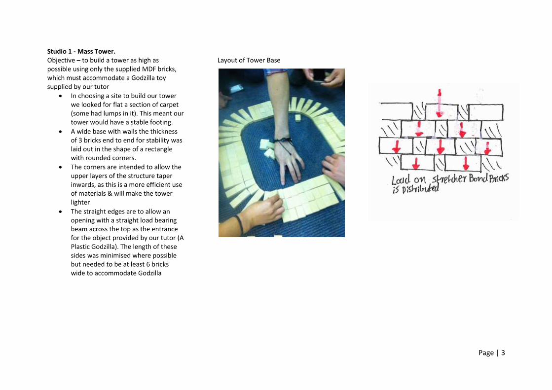
Studio 1 - Mass Tower. Objective – to build a tower as high as possible using only the supplied MDF bricks, which must accommodate a Godzilla toy supplied by our tutor
In choosing a site to build our tower we looked for flat a section of carpet (some had lumps in it). This meant our tower would have a stable footing.
A wide base with walls the thickness of 3 bricks end to end for stability was laid out in the shape of a rectangle with rounded corners.
The corners are intended to allow the upper layers of the structure taper inwards, as this is a more efficient use of materials & will make the tower lighter
The straight edges are to allow an opening with a straight load bearing beam across the top as the entrance for the object provided by our tutor (A Plastic Godzilla). The length of these sides was minimised where possible but needed to be at least 6 bricks wide to accommodate Godzilla
Layout of Tower Base
Page | 4
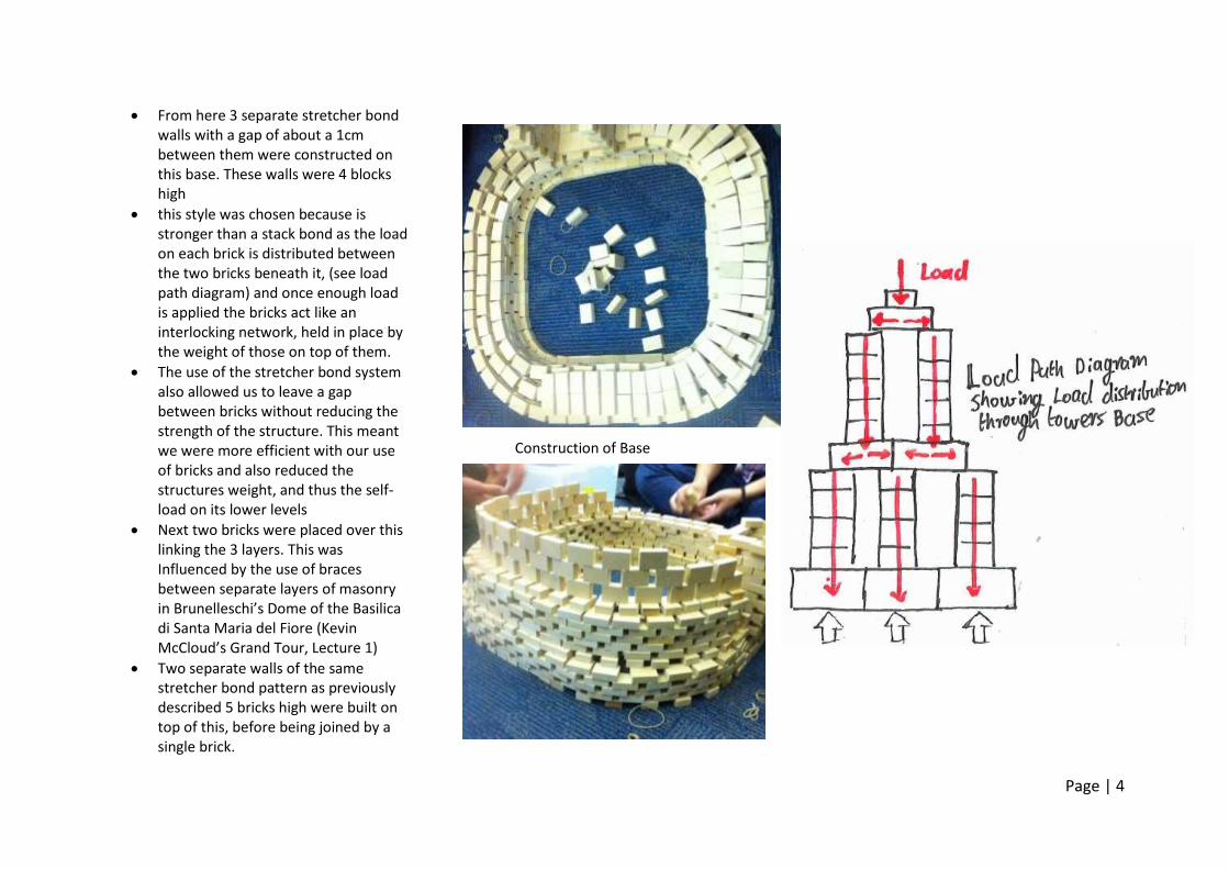
From here 3 separate stretcher bond walls with a gap of about a 1cm between them were constructed on this base. These walls were 4 blocks high
this style was chosen because is stronger than a stack bond as the load on each brick is distributed between the two bricks beneath it, (see load path diagram) and once enough load is applied the bricks act like an interlocking network, held in place by the weight of those on top of them.
The use of the stretcher bond system also allowed us to leave a gap between bricks without reducing the strength of the structure. This meant we were more efficient with our use of bricks and also reduced the structures weight, and thus the self-load on its lower levels
Next two bricks were placed over this linking the 3 layers. This was Influenced by the use of braces between separate layers of masonry in Brunelleschi’s Dome of the Basilica di Santa Maria del Fiore (Kevin McCloud’s Grand Tour, Lecture 1)
Two separate walls of the same stretcher bond pattern as previously described 5 bricks high were built on top of this, before being joined by a single brick.
Construction of Base
Page | 5
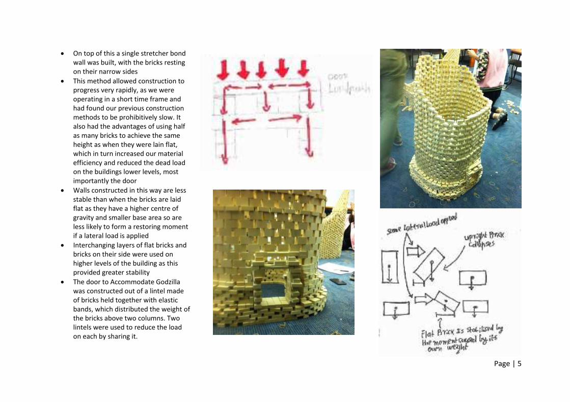
On top of this a single stretcher bond wall was built, with the bricks resting on their narrow sides
This method allowed construction to progress very rapidly, as we were operating in a short time frame and had found our previous construction methods to be prohibitively slow. It also had the advantages of using half as many bricks to achieve the same height as when they were lain flat, which in turn increased our material efficiency and reduced the dead load on the buildings lower levels, most importantly the door
Walls constructed in this way are less stable than when the bricks are laid flat as they have a higher centre of gravity and smaller base area so are less likely to form a restoring moment if a lateral load is applied
Interchanging layers of flat bricks and bricks on their side were used on higher levels of the building as this provided greater stability
The door to Accommodate Godzilla was constructed out of a lintel made of bricks held together with elastic bands, which distributed the weight of the bricks above two columns. Two lintels were used to reduce the load on each by sharing it.
Page | 6
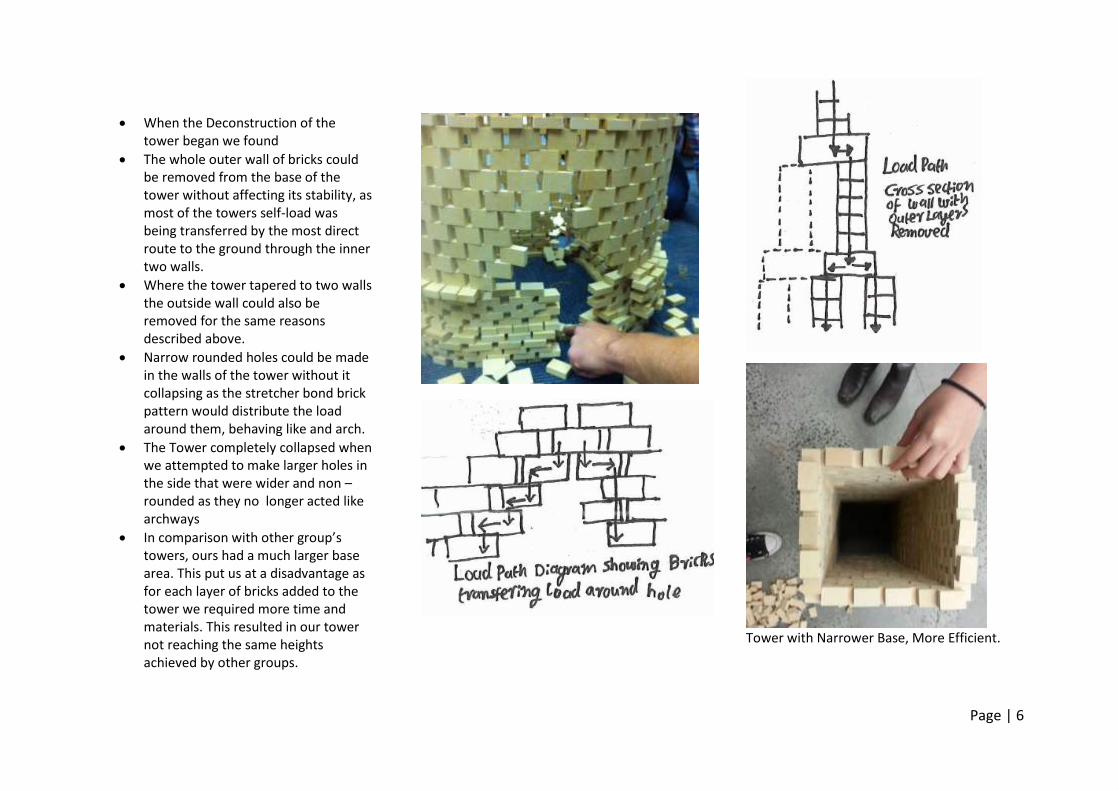
When the Deconstruction of the tower began we found
The whole outer wall of bricks could be removed from the base of the tower without affecting its stability, as most of the towers self-load was being transferred by the most direct route to the ground through the inner two walls.
Where the tower tapered to two walls the outside wall could also be removed for the same reasons described above.
Narrow rounded holes could be made in the walls of the tower without it collapsing as the stretcher bond brick pattern would distribute the load around them, behaving like and arch.
The Tower completely collapsed when we attempted to make larger holes in the side that were wider and non – rounded as they no longer acted like archways
In comparison with other group’s towers, ours had a much larger base area. This put us at a disadvantage as for each layer of bricks added to the tower we required more time and materials. This resulted in our tower not reaching the same heights achieved by other groups.
Tower with Narrower Base, More Efficient.
Page | 7
Wk 1 References ENVS10003 (2014, March 6). Melbourne’s Bluestone. Retrieved March 11, 2014, from http://youtube.com/watch?v=CGMA71_3H6o&feature=youtu.be ENVS10003 (2014, March 5). Introduction to Materials. Retrieved March 11, 2014, from http://youtube.com/watch?v=s4CJ8o_1jbg&feature=youtu.be ENVS10003 (2014, March 5). W01 s1 Load Path Diagrams. Retrieved March 11, 2014, from http://www.youtube.com/watch?v=y__V15j3IX4&feature=youtu.be McCloud, K. (Presenter). (2009). Episode 2 [television series episode]. Kevin McCloud’s Grand Tour. England: Channel 4 [UK] Ching, F. (2008) Building Construction Illustrated (4th Ed.). Hoboken, NJ: John Wiley & Sons.
Page | 8
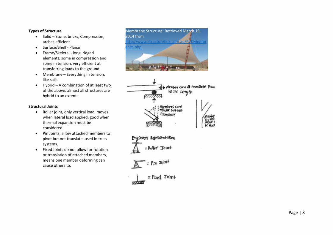
Types of Structure
Solid – Stone, bricks, Compression, arches efficient
Surface/Shell - Planar
Frame/Skeletal - long, ridged elements, some in compression and some in tension, very efficient at transferring loads to the ground.
Membrane – Everything in tension, like sails
Hybrid – A combination of at least two of the above. almost all structures are hybrid to an extent
Structural Joints
Roller joint, only vertical load, moves when lateral load applied, good when thermal expansion must be considered
Pin Joints, allow attached members to pivot but not translate, used in truss systems.
Fixed Joints do not allow for rotation or translation of attached members, means one member deforming can cause others to.
Membrane Structure: Retrieved March 19, 2014 from http://www.structureflex.com.au/PVCMembranes.php
Page | 9
Considerations When Building Precedent is often a good guide
Regulatory Constraints
Aesthetic
Economic – Initial Cost & life cycle cost (longevity and cost to run over lifetime)
Environmental Impact – Linked to lifecycle cost. Good design can reduce electricity & water use & waste during construction. Consider embodied energy/CO2– the amount of Energy/CO2 used in sourcing manufacturing & transporting a product. Recyclability of products, try to think of construction process as a circle not linear.
Common ESD Strategies – local materials, material efficiency, thermal mass, night air purging, solar & wind energy, cross ventilation, insulation, water harvesting & recycling, smart solar design
Performance Requirements – Insulation of heat & Noise, fire resistance, resistance to corrosion, strength
Constructability – Difficulty of construction. Labour, equipment, access to site.
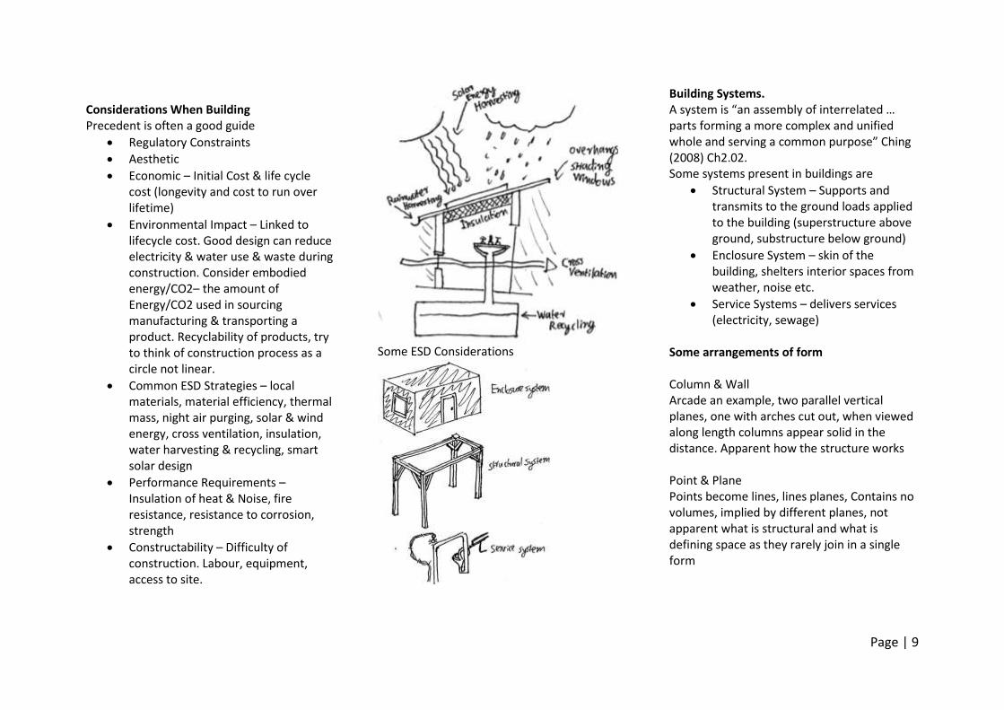
Some ESD Considerations
Building Systems. A system is “an assembly of interrelated … parts forming a more complex and unified whole and serving a common purpose” Ching (2008) Ch2.02. Some systems present in buildings are
Structural System – Supports and transmits to the ground loads applied to the building (superstructure above ground, substructure below ground)
Enclosure System – skin of the building, shelters interior spaces from weather, noise etc.
Service Systems – delivers services (electricity, sewage)
Some arrangements of form Column & Wall Arcade an example, two parallel vertical planes, one with arches cut out, when viewed along length columns appear solid in the distance. Apparent how the structure works Point & Plane Points become lines, lines planes, Contains no volumes, implied by different planes, not apparent what is structural and what is defining space as they rarely join in a single form
Page | 10
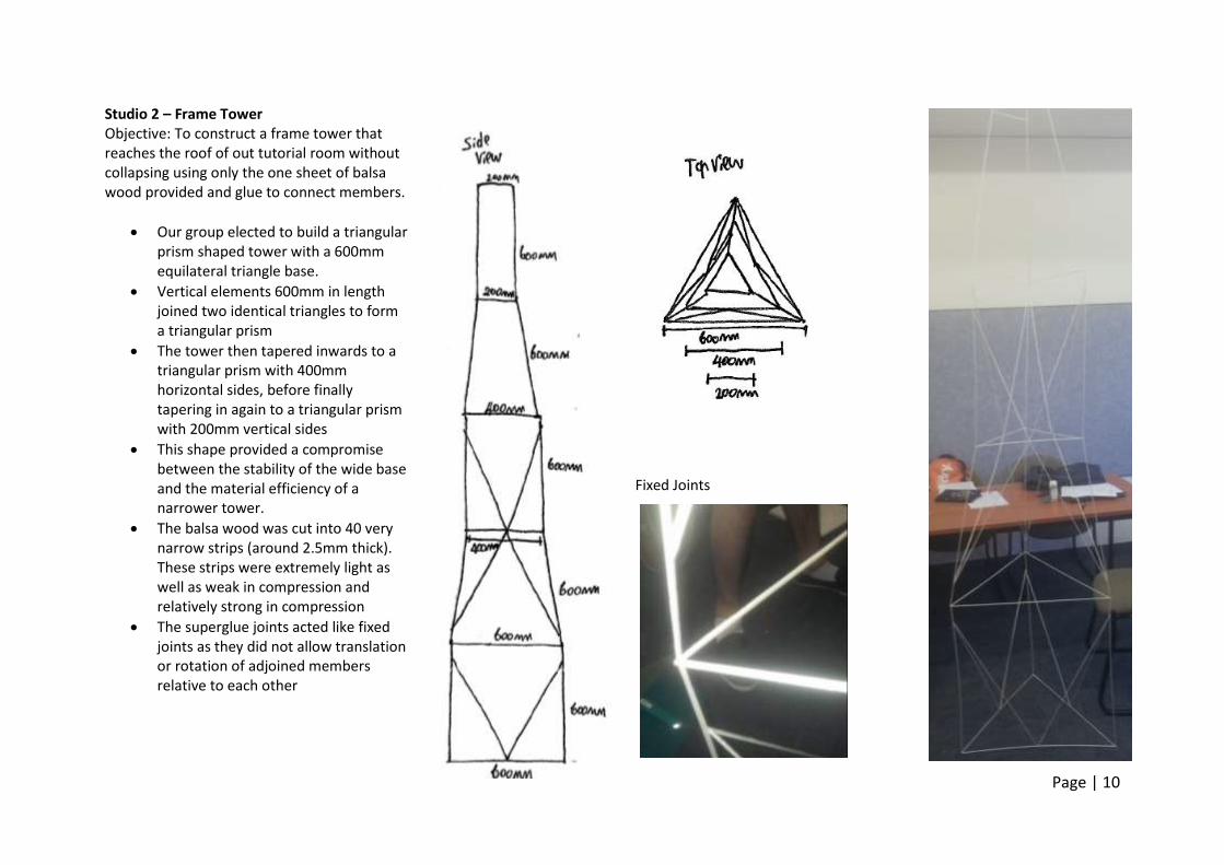
Studio 2 – Frame Tower Objective: To construct a frame tower that reaches the roof of out tutorial room without collapsing using only the one sheet of balsa wood provided and glue to connect members.
Our group elected to build a triangular prism shaped tower with a 600mm equilateral triangle base.
Vertical elements 600mm in length joined two identical triangles to form a triangular prism
The tower then tapered inwards to a triangular prism with 400mm horizontal sides, before finally tapering in again to a triangular prism with 200mm vertical sides
This shape provided a compromise between the stability of the wide base and the material efficiency of a narrower tower.
The balsa wood was cut into 40 very narrow strips (around 2.5mm thick). These strips were extremely light as well as weak in compression and relatively strong in compression
The superglue joints acted like fixed joints as they did not allow translation or rotation of adjoined members relative to each other
Fixed Joints
Page | 11
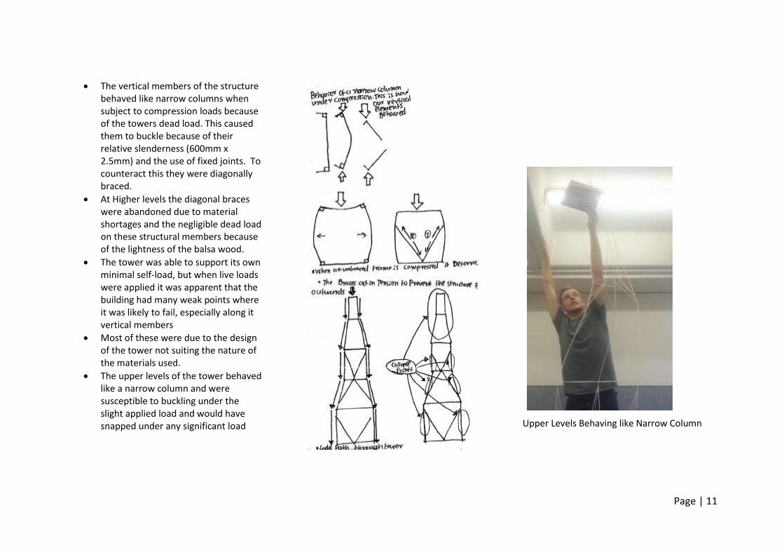
The vertical members of the structure behaved like narrow columns when subject to compression loads because of the towers dead load. This caused them to buckle because of their relative slenderness (600mm x 2.5mm) and the use of fixed joints. To counteract this they were diagonally braced.
At Higher levels the diagonal braces were abandoned due to material shortages and the negligible dead load on these structural members because of the lightness of the balsa wood.
The tower was able to support its own minimal self-load, but when live loads were applied it was apparent that the building had many weak points where it was likely to fail, especially along it vertical members
Most of these were due to the design of the tower not suiting the nature of the materials used.
The upper levels of the tower behaved like a narrow column and were susceptible to buckling under the slight applied load and would have snapped under any significant load
Upper Levels Behaving like Narrow Column
Page | 12
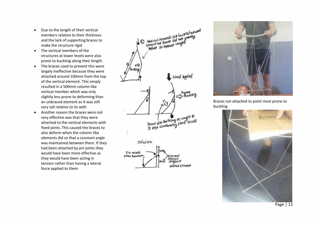
Due to the length of their vertical members relative to their thickness and the lack of supporting braces to make the structure rigid
The vertical members of the structures at lower levels were also prone to buckling along their length.
The braces used to prevent this were largely ineffective because they were attached around 100mm from the top of the vertical element. This simply resulted in a 500mm column like vertical member which was only slightly less prone to deforming than an unbraced element as it was still very tall relative to its with
Another reason the braces were not very effective was that they were attached to the vertical elements with fixed joints. This caused the braces to also deform when the column like elements did so that a constant angle was maintained between them. If they had been attached by pin joints they would have been more effective as they would have been acting in tension rather than having a lateral force applied to them
Braces not attached to point most prone to buckling
Page | 13
Braces Bending to Maintain Fixed Angle Wk 2 References Envs10003 (2014, March 9). W02 c1 Construction Systems. Retrieved March 13, 2014, from http://www.youtube.com/watch?v=8zTarEeGXOo&feature=youtu.be ENVS10003 (2014, March 9). W02 s1 Structural Systems. Retrieved March 13, 2014, from http://www.youtube.com/watch?v=l--JtPpI8uw&feature=youtu.be ENVS10003 (2014, March 9). W02 s2 Structural Joints. Retrieved March 13, 2014, from http://www.youtube.com/watch?v=kxRdY0jSoJo&feature=youtu.be ENVS10003 (2014, March 9). ESD & Selecting Materials. Retrieved March 13, 2014, from http://www.youtube.com/watch?v=luxirHHxjIY&feature=youtu.be ENVS10003 (2014, March 9). Framework for Analysing Form. Retrieved March 13, 2014, from http://www.youtube.com/watch?v=KJ97Whk1kGU&feature=youtu.be Ching, F. (2008) Building Construction Illustrated (4th Ed.). Hoboken, NJ: John Wiley & Sons.
Page | 14
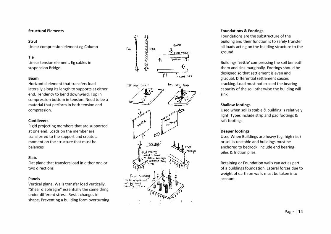
Structural Elements Strut Linear compression element eg Column Tie Linear tension element. Eg cables in suspension Bridge Beam Horizontal element that transfers load laterally along its length to supports at either end. Tendency to bend downward. Top in compression bottom in tension. Need to be a material that perform in both tension and compression. Cantilevers Rigid projecting members that are supported at one end. Loads on the member are transferred to the support and create a moment on the structure that must be balances Slab. Flat plane that transfers load in either one or two directions Panels Vertical plane. Walls transfer load vertically. “Shear diaphragm” essentially the same thing under different stress. Resist changes in shape, Preventing a building form overturning
Foundations & Footings Foundations are the substructure of the building and their function is to safely transfer all loads acting on the building structure to the ground Buildings ‘settle’ compressing the soil beneath them and sink marginally. Footings should be designed so that settlement is even and gradual. Differential settlement causes cracking. Load must not exceed the bearing capacity of the soil otherwise the building will sink. Shallow footings Used when soil is stable & building is relatively light. Types include strip and pad footings & raft footings Deeper footings Used When Buildings are heavy (eg. high rise) or soil is unstable and buildings must be anchored to bedrock. Include end bearing piles & friction piles. Retaining or Foundation walls can act as part of a buildings foundation. Lateral forces due to weight of earth on walls must be taken into account
Page | 15
Mass Construction Is made of unitised masses and transfers loads to the ground using only compression forces
Non Modular Rammed earth Monolithic stone Concrete – ‘Artificial Rock’
Standard mixture made of 1 part cement, 2 parts fine aggregate, 4 parts coarse aggregate and 0.5 parts water.
Formed by a chemical reaction between cement and water binding aggregate called curing.
Reinforced Concrete
Steel mesh or bars added, making it strong in tension as well as compression.
Properties
Fluid before it hardens so it can be easily shaped.
Poured into moulds made called formwork. Props & Bracing supports concretes weight during drying. Reaches 75% compressive strength after 7 days, full after 28.
Finishing textures can be added while concrete is wet (raking, Board & Batin) or dry (sandblasted).
Pigment can alter colour and aggregate can add texture, concrete can be polished.
High embodied energy, but very long lifespan, can be partially recycled as aggregate. Generally cost effective. Susceptible to water penetration.
Porous, can become saturated.
Tends to shrink over time.
Weak in tension strong in compression
In – Situ – Poured into formwork and cured on site. Sometimes Sacrificial formwork is left in place after concrete dries Limited time before concrete hardens and is unworkable, must be poured, vibrated to remove air bubbles and finished applied. Labour intensive. Used for structural purposes, floor slabs or non-standard elements
Construction joints divide slabs into more manageable sections to work
Control Joints required to absorb the thermal expansion and contraction of concrete over time.
Both potential weak points Pre Cast – Fabricates off site in a controlled environment and transported to site. More standardised outcome and higher quality product & finishes. Concrete is often in standard sized panels which has cost benefits and allows work on site to progress much
faster. Size limited by need to transport Panels often lifted into place with a crane. Rarely used in footings but common in Walls and columns. Roman Concrete
First developed in Ancient Rome, used large aggregate held together with cement paste. Less fluid than modern concrete. Volcanic residue called Potsilana made very strong concrete and would set it even in the presence of water
Pantheon Built in the 1st century AD in Rome. 6.15m Thick brick faced concrete walls in in drum like element supports 43.2m Diameter concrete dome. The largest concrete shell dome in existence, and was the largest span in existence until contemporary times. Made possible by the use of different aggregate materials footing –hard limestone – maximum compressive resistance. Higher up lighter rock called tufa was used, and on top of that a brick aggregate, in the actual shell volcanic pumice was used. ‘Oculus’ or the hole in the centre removes point that is most likely to fail. A compression ring of brick behaving like a horizontal arch prevented it pushing inward
Page | 16
Modular
Discrete units Masonry Discrete units held together by a bonding agent, usually mortar. Used to construct walls, columns, lintels, vaults, domes Terminology
Bond – arrangement of units
Course – Horizontal row of units,
Joint – the way units are connected. Materials
Stone
Earth – Mud Brick or Rammed Earth.
Clay – Bricks
Concrete – monolithic or block Bricks
Clay shaped then hardened by heat in kiln.
Oldest bricks handmade, then machine pressed now extruded.
Colour varies because of different compositions of clay. Fe For red, Mn for Grey.
Can become soaked after prolonged exposure to water and expand.
Long lifespan, easily re used or crushed into aggregate, tend to be locally produced but firing process is energy intensive. Relatively cheap but labour intensive
Concrete Blocks
Similar properties to brick but Chemically Manufactured and often larger.
Hollow, improving insulation and allowing for reinforcement.
Used to construct walls, divided into load bearing and non-load bearing blocks.
Carbon footprint High but can be reduced by using recycled products in manufacture.
Cheap but labour intensive. Shrink with age, opposite to brick but both require movement joints.
Stone 3 Types Igneous – dense, hard. Eg basalt bluestone granite, used in foundations. very strong in compression and impervious. Sedimentary – softer, less dense. Eg Limestone & sandstone. favoured because it is easy to work. Light in colour Metamorphic – High cost, not often used in construction except in decorative veneer finishes Uses Gabion Wall – Rocks in wire cages, usually used in retaining walls rather than building Monolithic Stones – Large Individual stones forming individual units. Largely impractical.
Ashlar – stones carved into flat faced modular elements bonded together Rubble – Stones used as found and bonded together Properties vary hugely with chemical compositions. Re-usable, transport main impact on carbon footprint.
Page | 17
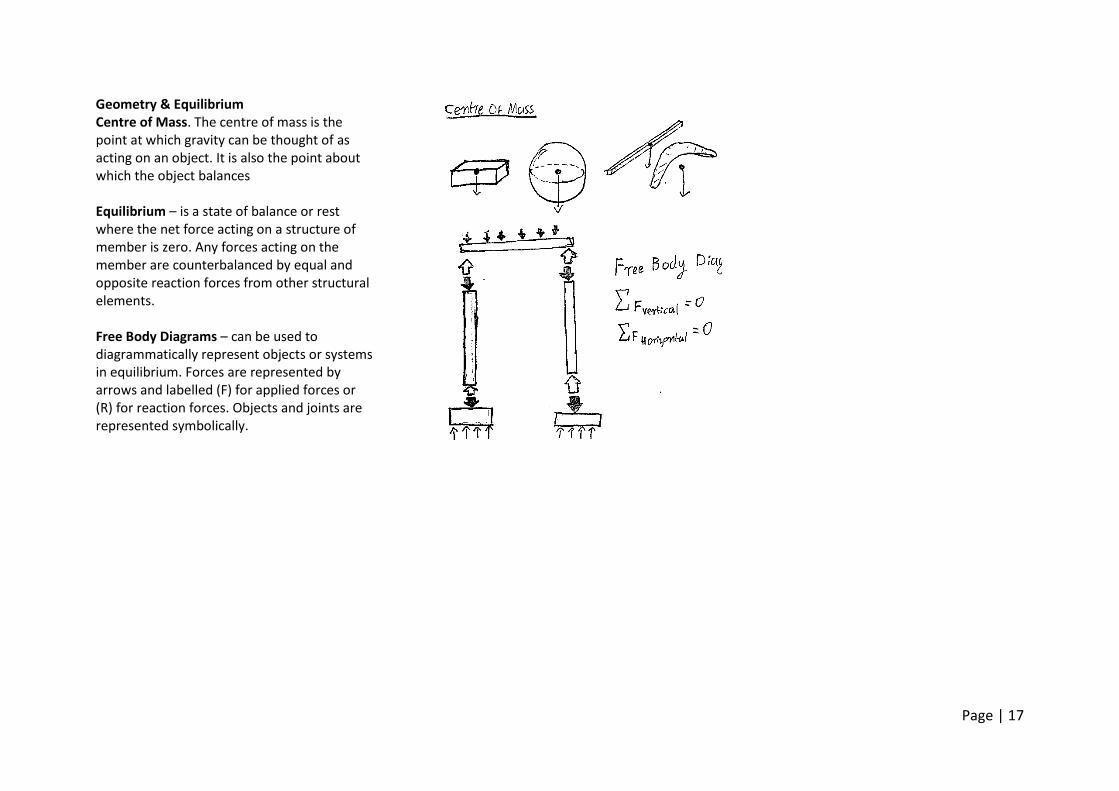
Geometry & Equilibrium Centre of Mass. The centre of mass is the point at which gravity can be thought of as acting on an object. It is also the point about which the object balances Equilibrium – is a state of balance or rest where the net force acting on a structure of member is zero. Any forces acting on the member are counterbalanced by equal and opposite reaction forces from other structural elements. Free Body Diagrams – can be used to diagrammatically represent objects or systems in equilibrium. Forces are represented by arrows and labelled (F) for applied forces or (R) for reaction forces. Objects and joints are represented symbolically.
Page | 18
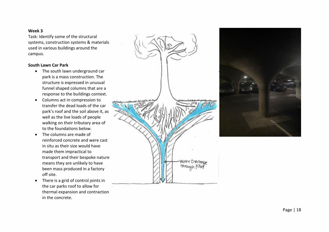
Week 3 Task: Identify some of the structural systems, construction systems & materials used in various buildings around the campus. South Lawn Car Park
The south lawn underground car park is a mass construction. The structure is expressed in unusual funnel shaped columns that are a response to the buildings context.
Columns act in compression to transfer the dead loads of the car park’s roof and the soil above it, as well as the live loads of people walking on their tributary area of to the foundations below.
The columns are made of reinforced concrete and were cast in situ as their size would have made them impractical to transport and their bespoke nature means they are unlikely to have been mass produced in a factory off site.
There is a grid of control joints in the car parks roof to allow for thermal expansion and contraction in the concrete.
Page | 19
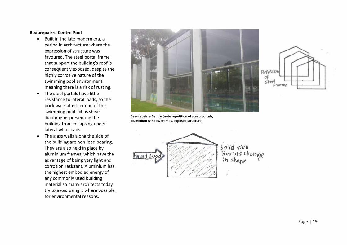
Beaurepairre Centre Pool
Built in the late modern era, a period in architecture where the expression of structure was favoured. The steel portal frame that support the building’s roof is consequently exposed, despite the highly corrosive nature of the swimming pool environment meaning there is a risk of rusting.
The steel portals have little resistance to lateral loads, so the brick walls at either end of the swimming pool act as shear diaphragms preventing the building from collapsing under lateral wind loads
The glass walls along the side of the building are non-load bearing. They are also held in place by aluminium frames, which have the advantage of being very light and corrosion resistant. Aluminium has the highest embodied energy of any commonly used building material so many architects today try to avoid using it where possible for environmental reasons.
Beaurepairre Centre (note repetition of steep portals, aluminium window frames, exposed structure)
Page | 20
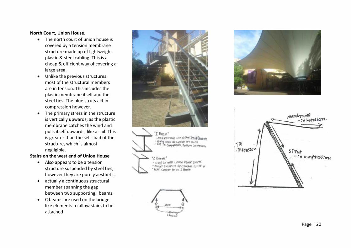
North Court, Union House.
The north court of union house is covered by a tension membrane structure made up of lightweight plastic & steel cabling. This is a cheap & efficient way of covering a large area.
Unlike the previous structures most of the structural members are in tension. This includes the plastic membrane itself and the steel ties. The blue struts act in compression however.
The primary stress in the structure is vertically upwards, as the plastic membrane catches the wind and pulls itself upwards, like a sail. This is greater than the self-load of the structure, which is almost negligible.
Stairs on the west end of Union House
Also appears to be a tension structure suspended by steel ties, however they are purely aesthetic.
actually a continuous structural member spanning the gap between two supporting I beams.
C beams are used on the bridge like elements to allow stairs to be attached
Page | 21
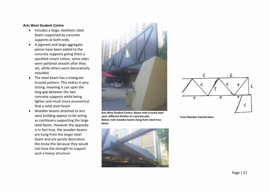
Arts West Student Centre
Includes a large, Aesthetic steel beam supported by concrete supports at both ends.
A pigment and large aggregate pieces have been added to the concrete supports giving them a speckled cream colour, some sides were polished smooth after they set, while others were decoratively moulded.
The steel beam has a triangular trussed pattern. This makes it very strong, meaning it can span the long gap between the two concrete supports while being lighter and much more economical that a solid steel beam
Wooden beams attached to arts west building appear to be acting as cantilevers supporting the large steel beam. However the opposite is in fact true, the wooden beams are hung from the larger steel beam and are purely decorative. We know this because they would not have the strength to support such a heavy structure.
Arts West Student Centre: Above note trussed steel span, different finishes on concrete pier. Below: note wooden beams hung from steel truss beam.
Truss Member Classification
Page | 22
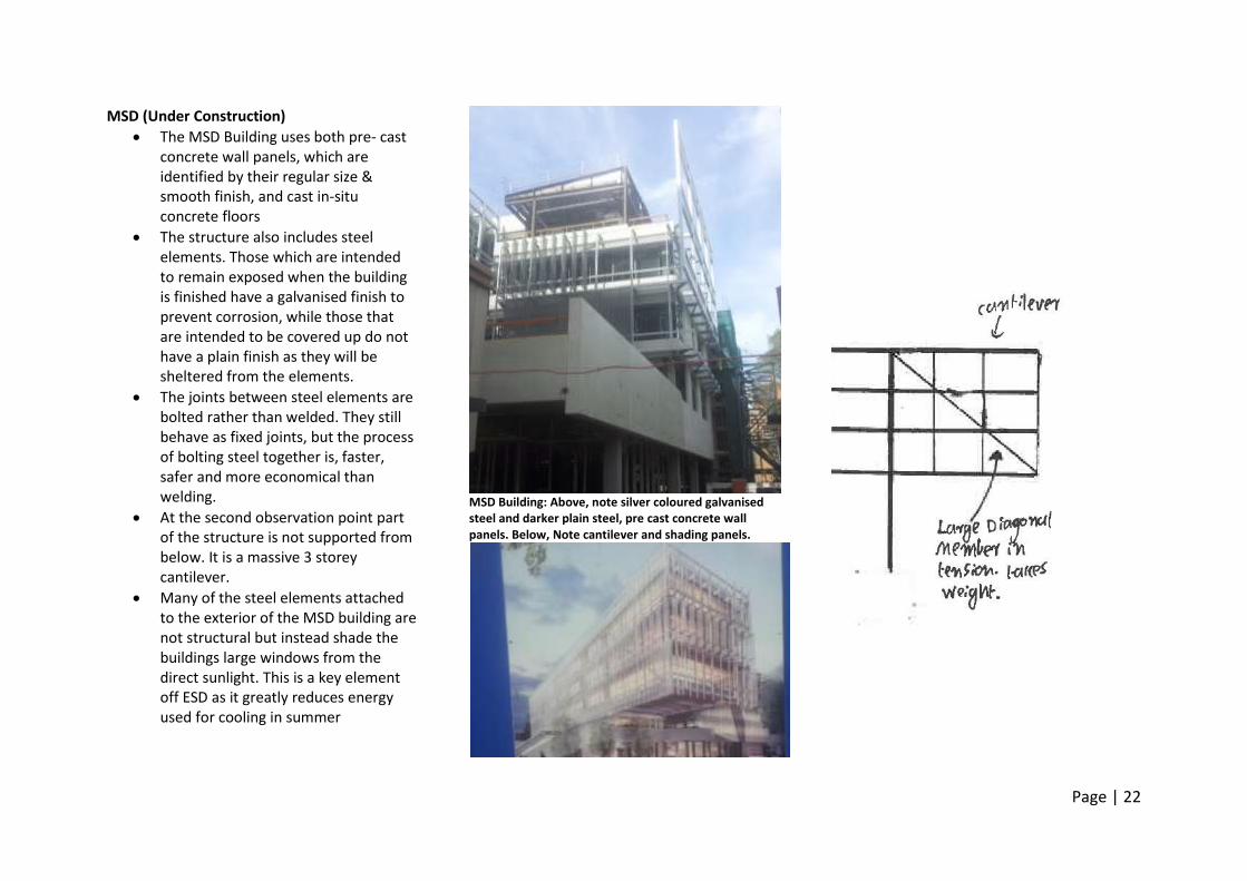
MSD (Under Construction)
The MSD Building uses both pre- cast concrete wall panels, which are identified by their regular size & smooth finish, and cast in-situ concrete floors
The structure also includes steel elements. Those which are intended to remain exposed when the building is finished have a galvanised finish to prevent corrosion, while those that are intended to be covered up do not have a plain finish as they will be sheltered from the elements.
The joints between steel elements are bolted rather than welded. They still behave as fixed joints, but the process of bolting steel together is, faster, safer and more economical than welding.
At the second observation point part of the structure is not supported from below. It is a massive 3 storey cantilever.
Many of the steel elements attached to the exterior of the MSD building are not structural but instead shade the buildings large windows from the direct sunlight. This is a key element off ESD as it greatly reduces energy used for cooling in summer
MSD Building: Above, note silver coloured galvanised steel and darker plain steel, pre cast concrete wall panels. Below, Note cantilever and shading panels.
Page | 23
Wk 3 references ENVS100003 (2014, March 17). W03_s1 STRUCTURAL ELEMENTS. Retrieved March 20, 2014, from http://www.youtube.com/watch?v=wQIa1O6fp98&feature=youtu.be ENVS10003 (2014, March 17). W03_c1 FOOTINGS & FOUDATIONS. Retrieved March 20, 2014, from http://www.youtube.com/watch?v=PAcuwrecIz8&feature=youtu.be ENVS10003 (2014, March 16). W03_m2 INTRODUCTION TO MASONRY. Retrieved March 21, 2014, from http://www.youtube.com/watch?v=DC8Hv8AKQ8A&feature=youtu.be ENVS10003 (2014, March 16). W03_m1 INTRODUCTON TO MASS CONSTRUCTION. Retrieved March 21, 2014, from http://www.youtube.com/watch?v=8Au2upE9JN8&feature=youtu.be ENVS1003 (2014, March 16). W03_m5 CONCRETE BLOCKS. Retrieved March 21, 2014 from http://www.youtube.com/watch?v=geJv5wZQtRQ&feature=youtu.be ENVS10003 (2014, March 16). W03_m3 BRICKS. Retrieved March 21, 2014, from http://www.youtube.com/watch?v=4lYlQhkMYmE&feature=youtu.be ENVS10003 (2014, March 25). W4_m1 Concrete. Retrieved March 27, 2014, from http://www.youtube.com/watch?v=c1M19C25MLU&feature=youtu.be ENVS10003 (2014, March 25). W04_m3 PRE CAST CONCRETE. Retrieved March 27, 2014, from http://www.youtube.com/watch?v=scYY-MMezI0&feature=youtu.be
ENVS10003 (2014, march 25). W04_m2 IN SITU CONCRETE. Retrieved March 27, 2014, from http://www.youtube.com/watch?v=c3zW_TBGjfE&feature=youtu.be Ching, Francis D.K., Building Construction Illustrated. Wiley & Sons, Inc., 2011 e-Book Vassigh, Shahin, InteracGve Structures Version 2.0, Wiley & Sons, Inc., 2008 DVD-ROM Hunt, T., Tony Hunt’s Structures Notebook, Architectural Press, 2003
Page | 24
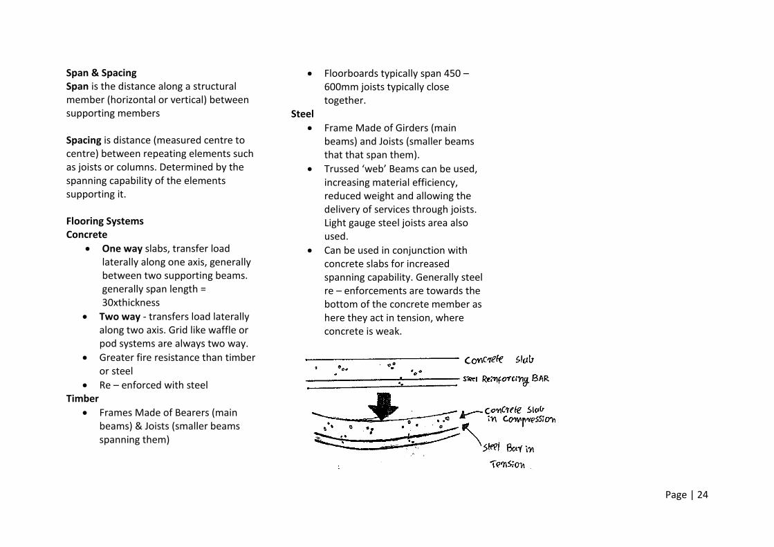
Span & Spacing Span is the distance along a structural member (horizontal or vertical) between supporting members Spacing is distance (measured centre to centre) between repeating elements such as joists or columns. Determined by the spanning capability of the elements supporting it. Flooring Systems Concrete
One way slabs, transfer load laterally along one axis, generally between two supporting beams. generally span length = 30xthickness
Two way - transfers load laterally along two axis. Grid like waffle or pod systems are always two way.
Greater fire resistance than timber or steel
Re – enforced with steel Timber
Frames Made of Bearers (main beams) & Joists (smaller beams spanning them)
Floorboards typically span 450 – 600mm joists typically close together.
Steel
Frame Made of Girders (main beams) and Joists (smaller beams that that span them).
Trussed ‘web’ Beams can be used, increasing material efficiency, reduced weight and allowing the delivery of services through joists. Light gauge steel joists area also used.
Can be used in conjunction with concrete slabs for increased spanning capability. Generally steel re – enforcements are towards the bottom of the concrete member as here they act in tension, where concrete is weak.
Page | 25
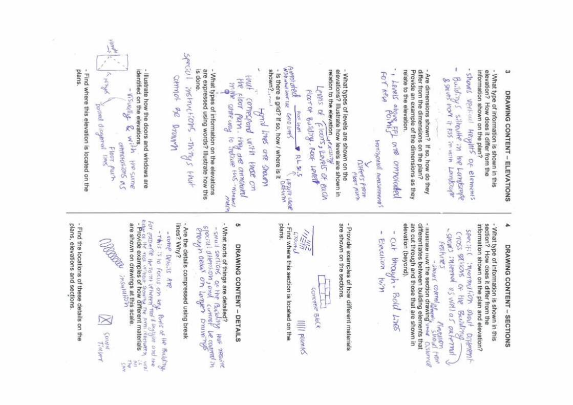
Week 4 Scale, Annotation and working Drawing conventions Activity Scale, in terms of construction documentation, is a numerical factor by which the size of drawings of buildings are multiplied to give their actual size. For example, when a drawing is at a scale of 1:100, the actual structure is 100 times larger than the drawing. This can be thought of as 1cm on paper representing 100cm in the building. The use of scale allows for large structures to be represented on ordinary paper. This is more practical than a life size representation of the building. A 1:1 scale construction document would be impractical to handle, store and print. Scale also allows documents to provide an accurate representation of the actual size of a buildings elements. This is because it allows people to measure the size of the drawn representation of the elements and multiply the result by a numerical factor, giving the elements actual size. The units used in construction documentation are millimetres (mm) and meters (M). Millimetres are useful for precisely describing the size of small structural elements. A meter is 1000mm and is a more practical unit of measure for larger structural elements.
Page | 26
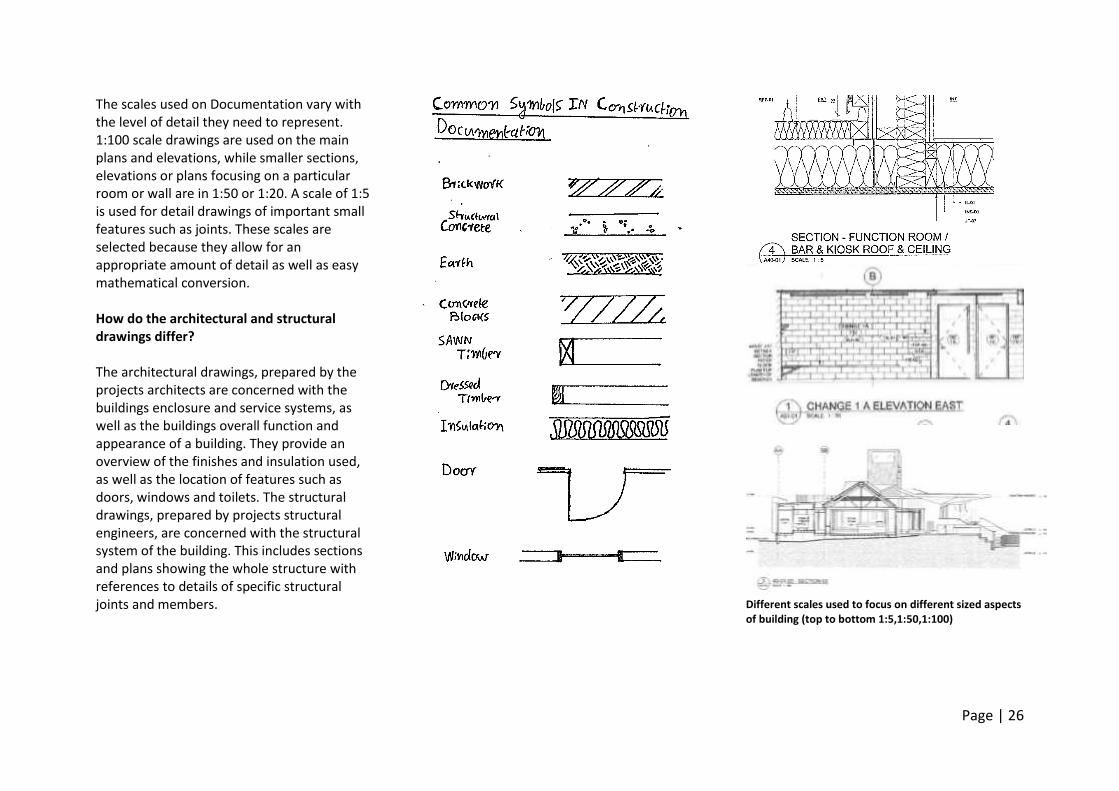
The scales used on Documentation vary with the level of detail they need to represent. 1:100 scale drawings are used on the main plans and elevations, while smaller sections, elevations or plans focusing on a particular room or wall are in 1:50 or 1:20. A scale of 1:5 is used for detail drawings of important small features such as joints. These scales are selected because they allow for an appropriate amount of detail as well as easy mathematical conversion. How do the architectural and structural drawings differ? The architectural drawings, prepared by the projects architects are concerned with the buildings enclosure and service systems, as well as the buildings overall function and appearance of a building. They provide an overview of the finishes and insulation used, as well as the location of features such as doors, windows and toilets. The structural drawings, prepared by projects structural engineers, are concerned with the structural system of the building. This includes sections and plans showing the whole structure with references to details of specific structural joints and members.
Different scales used to focus on different sized aspects of building (top to bottom 1:5,1:50,1:100)
Page | 27
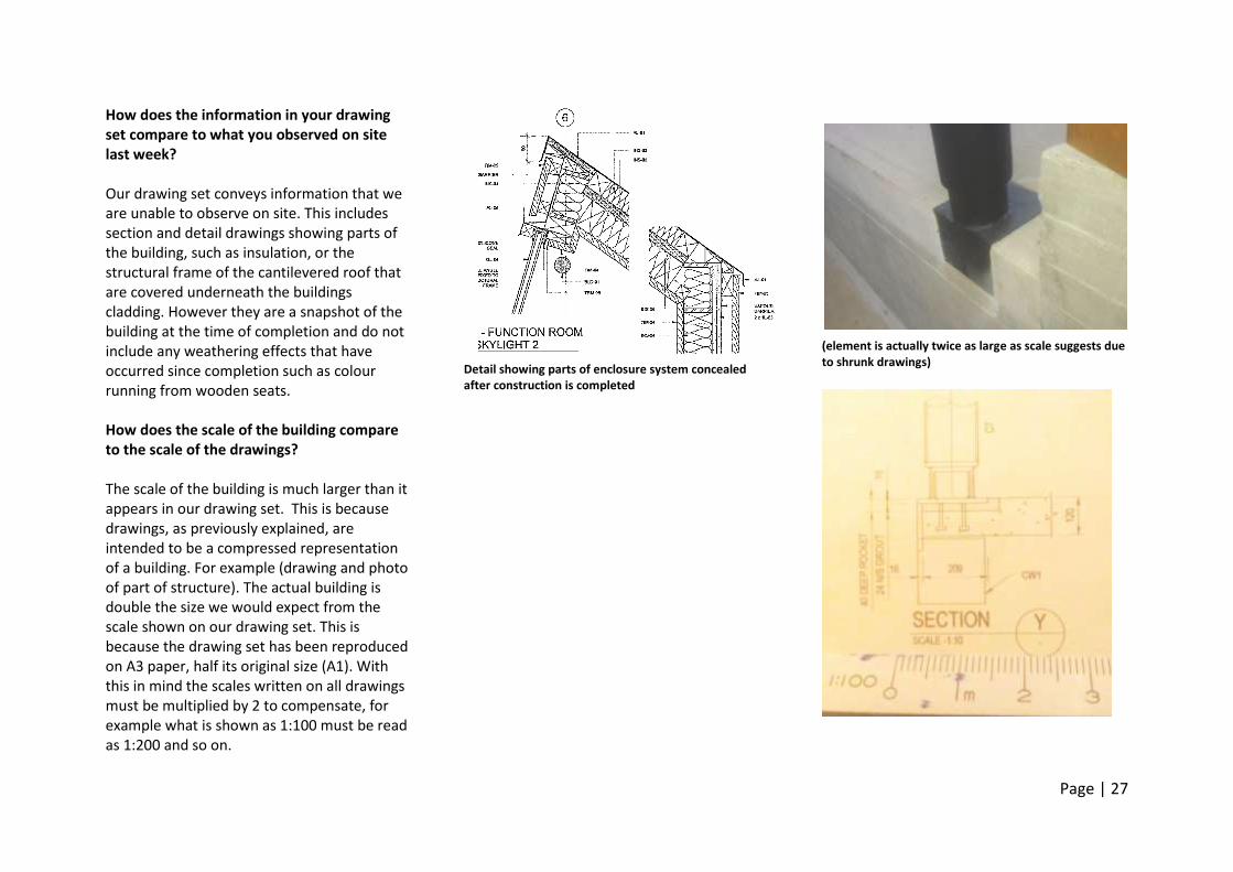
How does the information in your drawing set compare to what you observed on site last week? Our drawing set conveys information that we are unable to observe on site. This includes section and detail drawings showing parts of the building, such as insulation, or the structural frame of the cantilevered roof that are covered underneath the buildings cladding. However they are a snapshot of the building at the time of completion and do not include any weathering effects that have occurred since completion such as colour running from wooden seats. How does the scale of the building compare to the scale of the drawings? The scale of the building is much larger than it appears in our drawing set. This is because drawings, as previously explained, are intended to be a compressed representation of a building. For example (drawing and photo of part of structure). The actual building is double the size we would expect from the scale shown on our drawing set. This is because the drawing set has been reproduced on A3 paper, half its original size (A1). With this in mind the scales written on all drawings must be multiplied by 2 to compensate, for example what is shown as 1:100 must be read as 1:200 and so on.
Detail showing parts of enclosure system concealed after construction is completed
(element is actually twice as large as scale suggests due to shrunk drawings)
Page | 28
Page | 29
Wk 4 references
Page | 30
ENVS10003 (2014, March 25) W04_c1 FLOORING SYSTEMS. Retrieved March 27, 2014 from http://www.youtube.com/watch?v=otKffehOWaw&feature=youtu.be Ching, F. (2008) Building Construction Illustrated (4th Ed.). Hoboken, NJ: John Wiley & Sons.
Page | 31
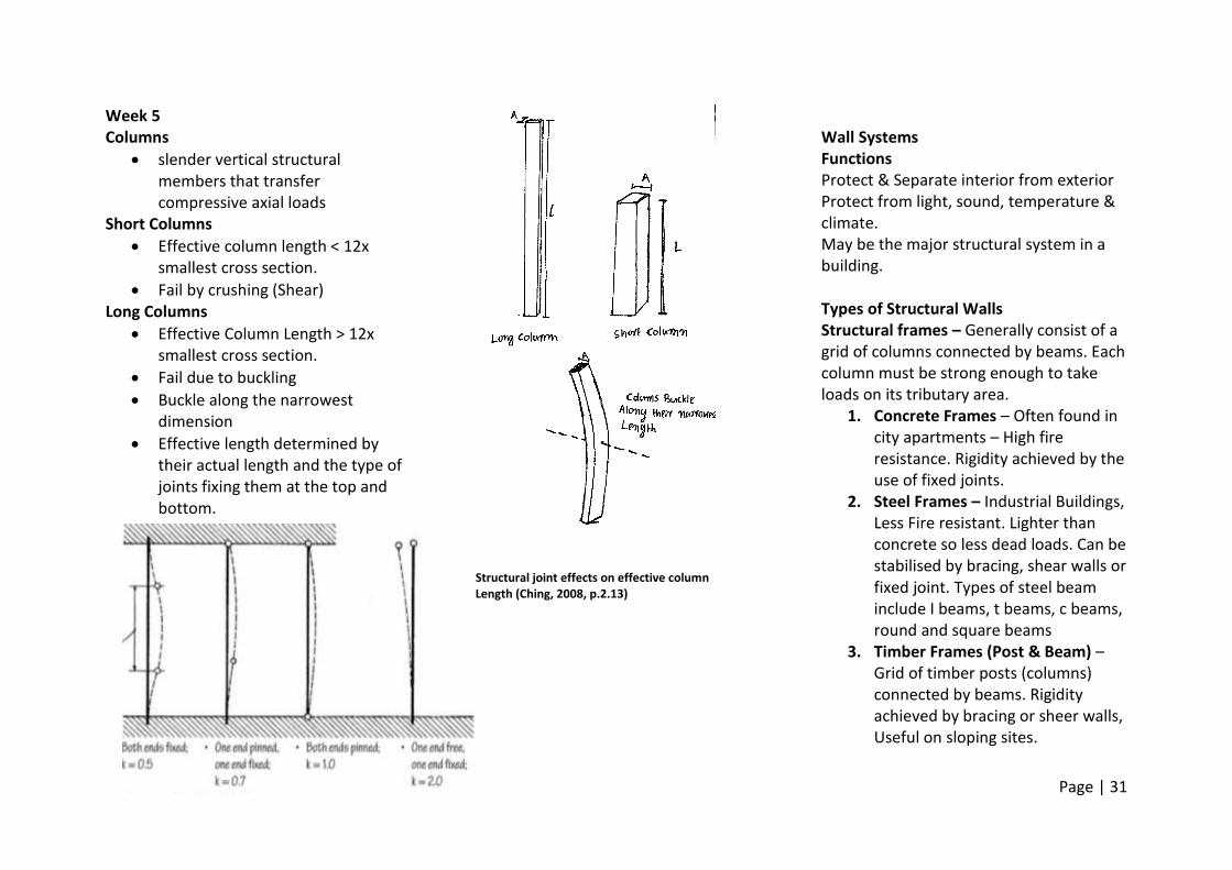
Week 5 Columns
slender vertical structural members that transfer compressive axial loads
Short Columns
Effective column length < 12x smallest cross section.
Fail by crushing (Shear) Long Columns
Effective Column Length > 12x smallest cross section.
Fail due to buckling
Buckle along the narrowest dimension
Effective length determined by their actual length and the type of joints fixing them at the top and bottom.
Structural joint effects on effective column Length (Ching, 2008, p.2.13)
Wall Systems Functions Protect & Separate interior from exterior Protect from light, sound, temperature & climate. May be the major structural system in a building. Types of Structural Walls Structural frames – Generally consist of a grid of columns connected by beams. Each column must be strong enough to take loads on its tributary area.
1. Concrete Frames – Often found in city apartments – High fire resistance. Rigidity achieved by the use of fixed joints.
2. Steel Frames – Industrial Buildings, Less Fire resistant. Lighter than concrete so less dead loads. Can be stabilised by bracing, shear walls or fixed joint. Types of steel beam include I beams, t beams, c beams, round and square beams
3. Timber Frames (Post & Beam) – Grid of timber posts (columns) connected by beams. Rigidity achieved by bracing or sheer walls, Useful on sloping sites.
Page | 32
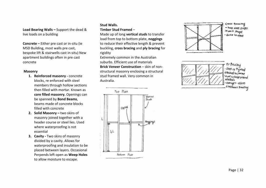
Load Bearing Walls – Support the dead & live loads on a building Concrete – Either pre cast or in-situ (ie MSD Building, most walls pre cast, bespoke lift & stairwells cast in-situ) New apartment buildings often in pre cast concrete Masonry
1. Reinforced masonry - concrete blocks, re enforced with steel members through hollow sections then filled with mortar. Known as core filled masonry. Openings can be spanned by Bond Beams, beams made of concrete blocks filled with concrete
2. Solid Masonry – two skins of masonry joined together with a header course or steel lies. Used where waterproofing is not essential
3. Cavity - Two skins of masonry divided by a cavity. Allows for waterproofing and insulation to be placed between layers. Occasional Perpends left open as Weep Holes to allow moisture to escape.
Stud Walls. Timber Stud Framed – Made up of long vertical studs to transfer load from top to bottom plate, noggings to reduce their effective length & prevent buckling, cross bracing and ply bracing for rigidity Extremely common in the Australian suburbs. Efficient use of materials Brick Veneer Construction – skin of non-structural masonry enclosing a structural stud framed wall. Very common in Australia.
Page | 33
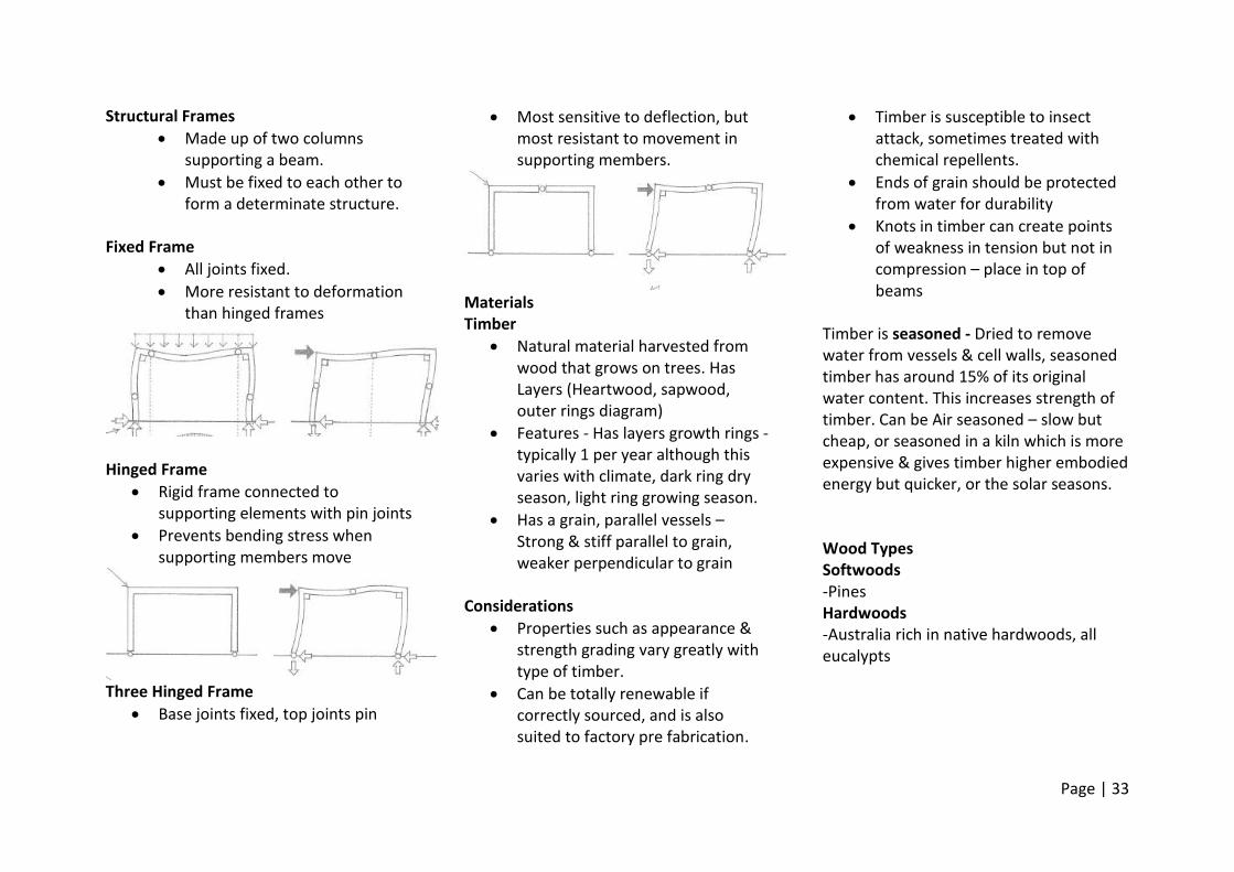
Structural Frames
Made up of two columns supporting a beam.
Must be fixed to each other to form a determinate structure.
Fixed Frame
All joints fixed.
More resistant to deformation than hinged frames
Hinged Frame
Rigid frame connected to supporting elements with pin joints
Prevents bending stress when supporting members move
Three Hinged Frame
Base joints fixed, top joints pin
Most sensitive to deflection, but most resistant to movement in supporting members.
Materials Timber
Natural material harvested from wood that grows on trees. Has Layers (Heartwood, sapwood, outer rings diagram)
Features - Has layers growth rings - typically 1 per year although this varies with climate, dark ring dry season, light ring growing season.
Has a grain, parallel vessels – Strong & stiff parallel to grain, weaker perpendicular to grain
Considerations
Properties such as appearance & strength grading vary greatly with type of timber.
Can be totally renewable if correctly sourced, and is also suited to factory pre fabrication.
Timber is susceptible to insect attack, sometimes treated with chemical repellents.
Ends of grain should be protected from water for durability
Knots in timber can create points of weakness in tension but not in compression – place in top of beams
Timber is seasoned - Dried to remove water from vessels & cell walls, seasoned timber has around 15% of its original water content. This increases strength of timber. Can be Air seasoned – slow but cheap, or seasoned in a kiln which is more expensive & gives timber higher embodied energy but quicker, or the solar seasons. Wood Types Softwoods -Pines Hardwoods -Australia rich in native hardwoods, all eucalypts
Page | 34
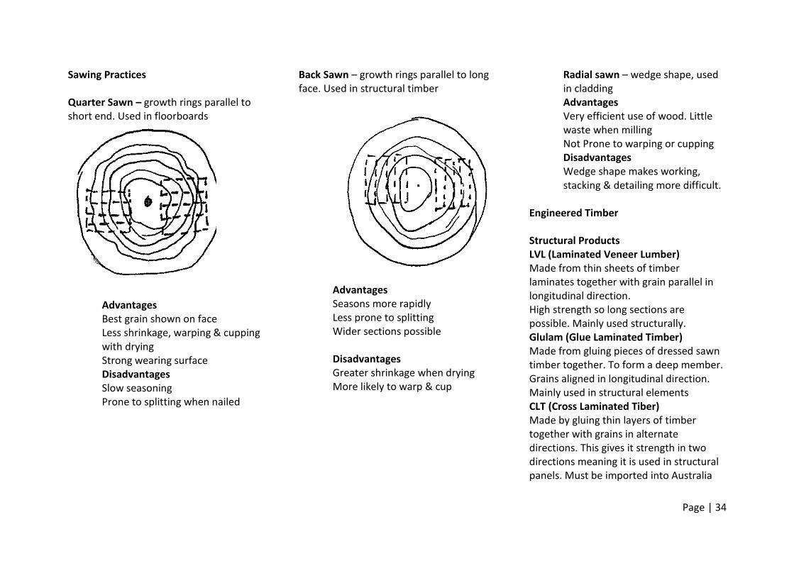
Sawing Practices Quarter Sawn – growth rings parallel to short end. Used in floorboards
Advantages Best grain shown on face Less shrinkage, warping & cupping with drying Strong wearing surface Disadvantages Slow seasoning Prone to splitting when nailed
Back Sawn – growth rings parallel to long face. Used in structural timber
Advantages Seasons more rapidly Less prone to splitting Wider sections possible Disadvantages Greater shrinkage when drying More likely to warp & cup
Radial sawn – wedge shape, used in cladding Advantages Very efficient use of wood. Little waste when milling Not Prone to warping or cupping Disadvantages Wedge shape makes working, stacking & detailing more difficult.
Engineered Timber Structural Products LVL (Laminated Veneer Lumber) Made from thin sheets of timber laminates together with grain parallel in longitudinal direction. High strength so long sections are possible. Mainly used structurally. Glulam (Glue Laminated Timber) Made from gluing pieces of dressed sawn timber together. To form a deep member. Grains aligned in longitudinal direction. Mainly used in structural elements CLT (Cross Laminated Tiber) Made by gluing thin layers of timber together with grains in alternate directions. This gives it strength in two directions meaning it is used in structural panels. Must be imported into Australia
Page | 35
Sheet Products Plywood Thin layers of wood glued together with grains in alternating directions. Used in ply bracing, structural bracing & joinery MDF Made of waste wood fibre bonded by wax & resin at high temperature. Very dense & has even properties. Used in non-structural applications Chipboard/Strandboard Made of wood chips with a specific orientation bound with wax & resin at high temperature. Can be used in structural elements or cladding. Other Manufactured Products -I Beams Ply web & solid timber flanges. This is lightweight and suitable for beams such as floor joists Box Beams Solid timber flanges joined by two plywood webs. Suitable for longer spans than I beams and also more aesthetic. Used in floor joists or rafters
Gehry ‘s Own Home Foreshadowed several directions in contemporary construction Everyday Materials
- Worked with discarded materials that he found around him in the streets of LA. Such as cardboard, sheet metal, chain fencing, plywood. Recycled lightweight everyday materials used to clad his buildings.
Page | 36
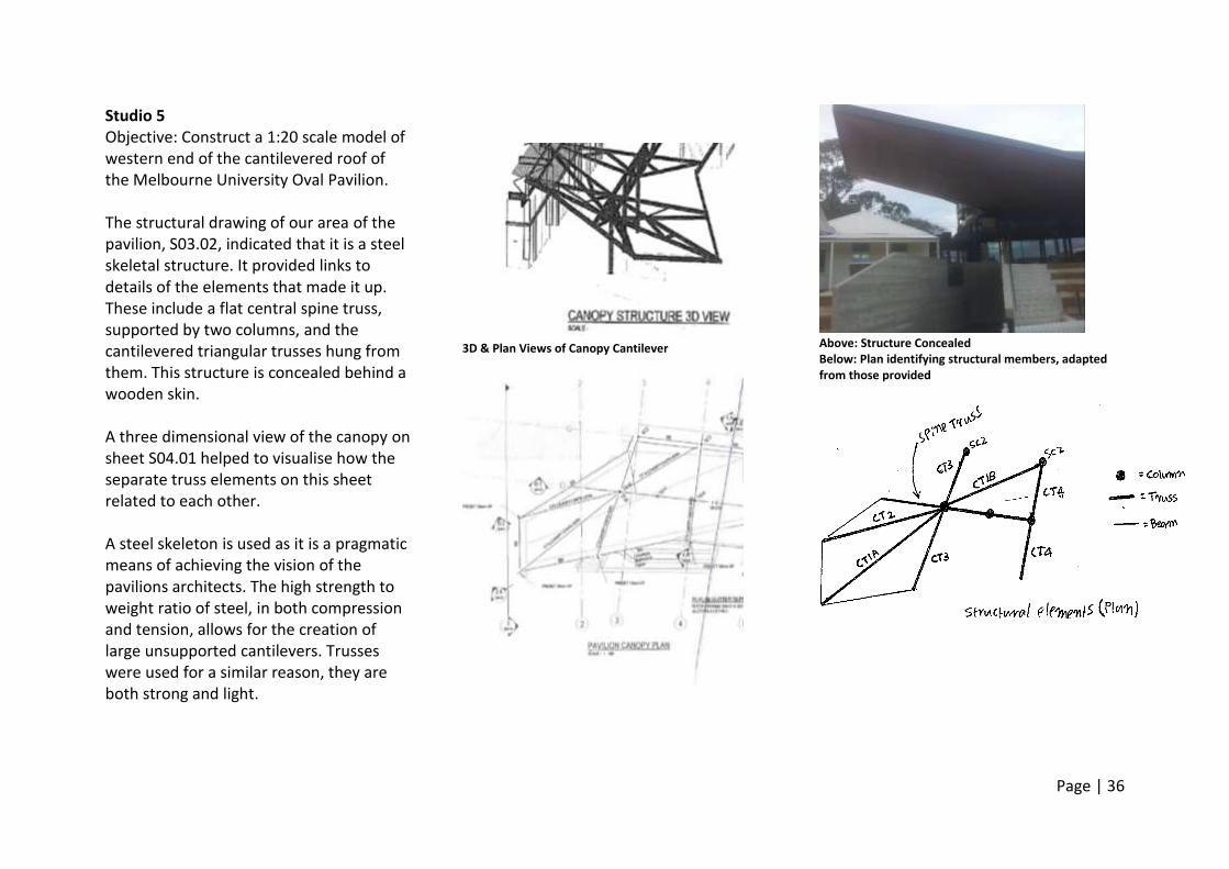
Studio 5 Objective: Construct a 1:20 scale model of western end of the cantilevered roof of the Melbourne University Oval Pavilion. The structural drawing of our area of the pavilion, S03.02, indicated that it is a steel skeletal structure. It provided links to details of the elements that made it up. These include a flat central spine truss, supported by two columns, and the cantilevered triangular trusses hung from them. This structure is concealed behind a wooden skin. A three dimensional view of the canopy on sheet S04.01 helped to visualise how the separate truss elements on this sheet related to each other. A steel skeleton is used as it is a pragmatic means of achieving the vision of the pavilions architects. The high strength to weight ratio of steel, in both compression and tension, allows for the creation of large unsupported cantilevers. Trusses were used for a similar reason, they are both strong and light.
3D & Plan Views of Canopy Cantilever
Above: Structure Concealed Below: Plan identifying structural members, adapted from those provided
Page | 37
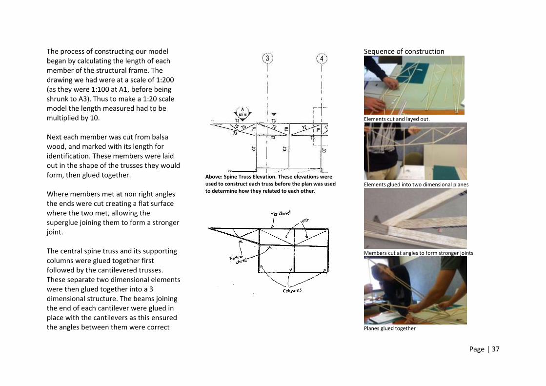
The process of constructing our model began by calculating the length of each member of the structural frame. The drawing we had were at a scale of 1:200 (as they were 1:100 at A1, before being shrunk to A3). Thus to make a 1:20 scale model the length measured had to be multiplied by 10. Next each member was cut from balsa wood, and marked with its length for identification. These members were laid out in the shape of the trusses they would form, then glued together. Where members met at non right angles the ends were cut creating a flat surface where the two met, allowing the superglue joining them to form a stronger joint. The central spine truss and its supporting columns were glued together first followed by the cantilevered trusses. These separate two dimensional elements were then glued together into a 3 dimensional structure. The beams joining the end of each cantilever were glued in place with the cantilevers as this ensured the angles between them were correct
Above: Spine Truss Elevation. These elevations were used to construct each truss before the plan was used to determine how they related to each other.
Sequence of construction
Elements cut and layed out.
Elements glued into two dimensional planes
Members cut at angles to form stronger joints
Planes glued together
Page | 38
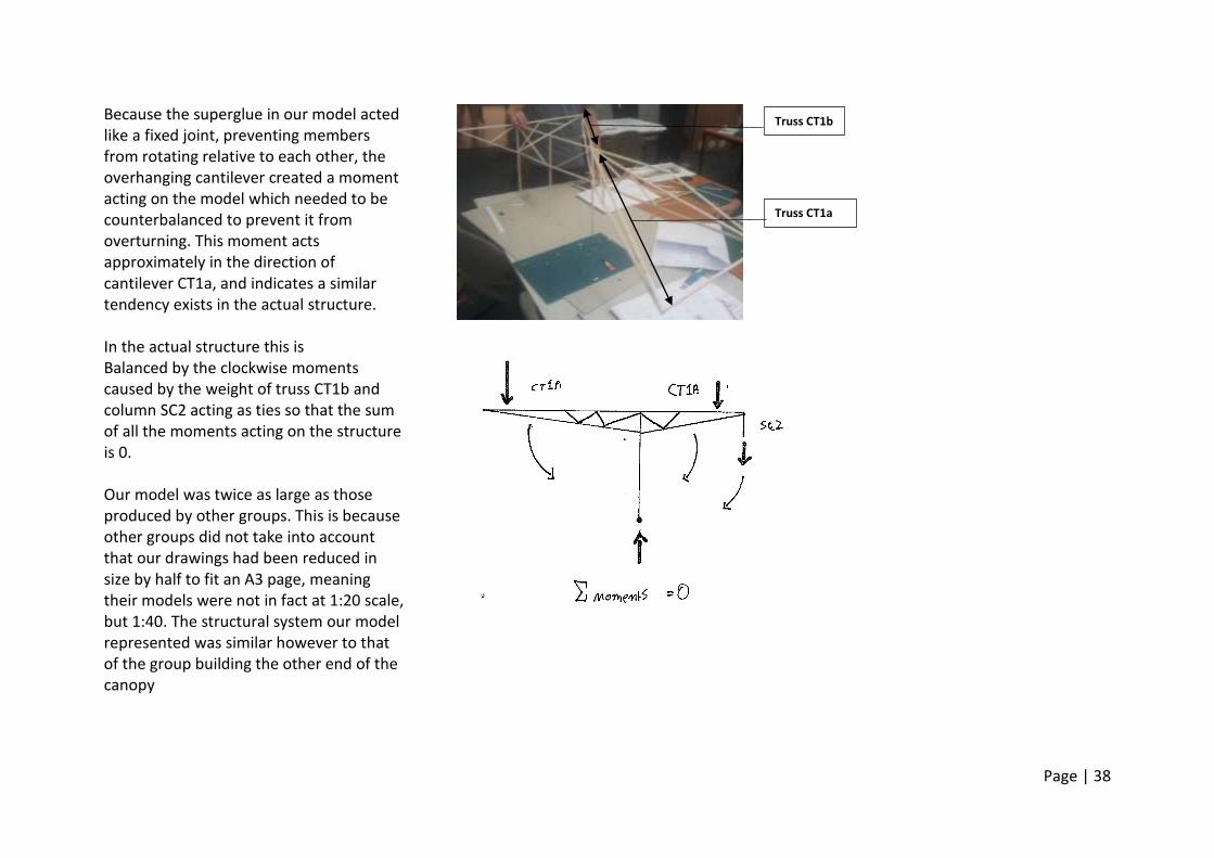
Because the superglue in our model acted like a fixed joint, preventing members from rotating relative to each other, the overhanging cantilever created a moment acting on the model which needed to be counterbalanced to prevent it from overturning. This moment acts approximately in the direction of cantilever CT1a, and indicates a similar tendency exists in the actual structure. In the actual structure this is Balanced by the clockwise moments caused by the weight of truss CT1b and column SC2 acting as ties so that the sum of all the moments acting on the structure is 0. Our model was twice as large as those produced by other groups. This is because other groups did not take into account that our drawings had been reduced in size by half to fit an A3 page, meaning their models were not in fact at 1:20 scale, but 1:40. The structural system our model represented was similar however to that of the group building the other end of the canopy
Truss CT1a
Truss CT1b
Page | 39
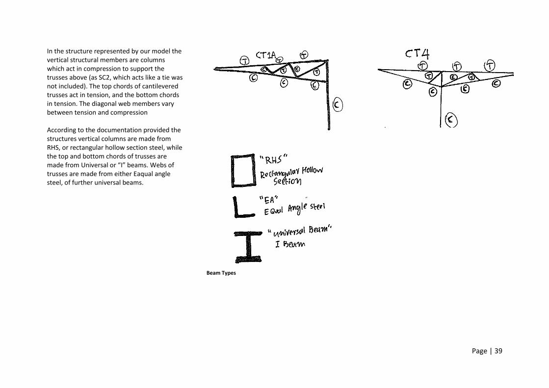
In the structure represented by our model the vertical structural members are columns which act in compression to support the trusses above (as SC2, which acts like a tie was not included). The top chords of cantilevered trusses act in tension, and the bottom chords in tension. The diagonal web members vary between tension and compression According to the documentation provided the structures vertical columns are made from RHS, or rectangular hollow section steel, while the top and bottom chords of trusses are made from Universal or “I” beams. Webs of trusses are made from either Eaqual angle steel, of further universal beams.
Beam Types
Page | 40
Wk 5 References ENVS10003. (2014, April 1). Gehry’s Own Home. Retrieved April 20, 2014, from http://www.youtube.com/watch?v=iqn2bYoO8j4&feature=youtu.be ENVS10003. (2014, April 1). W05_m3 Engineered Timber Products. Retrieved April 20, 2014 from http://www.youtube.com/watch?v=0YrYOGSwtVc&feature=youtu.be ENVS10003. (2014, April 1). W05_m2 Timber Properties and Considerations. Retrieved April 20, 2014 from http://www.youtube.com/watch?v=ul0r9OGkA9c&feature=youtu.be ENVS10003. (2014, April 1). W05_m1 From Wood to Timber. Retrieved April 20, 2014 from http://www.youtube.com/watch?v=YJL0vCwM0zg&feature=youtu.be ENVS10003. (2014, April 1). W05_c1 WALLS, GRIDS AND COLUMNS. Retrieved April 20, 2014 from http://www.youtube.com/watch?v=Vq41q6gUIjI&feature=youtu.be Ching, F. (2008) Building Construction Illustrated (4th Ed.). Hoboken, NJ: John Wiley & Sons. Cox Architects. (2012). Oval Pavilion Construction Drawings. Melbourne, AU
Page | 41
Week 6 Roof Systems Flat <3 Degrees Pitch
Generally not perfectly flat, leads to water ponding, adding dead load and leakage
Constructed from concrete slabs, trusses, beams & decking
Pitched/Sloping >3 Degrees Pitch
Rafters
Beams & purlins
Trusses Structural Materials Concrete
Most expensive
Large load requires significant supporting members
Also requires waterproof membrane to prevent water penetration.
Trafficable – Used in car parks and roof gardens
Structural Steel Frames
Much more common – Cheaper industrial buildings
Flat – Primary & secondary roof beams.
Sloping – Consists of roof beams and purlins.
Portal Frame – Series of braced rigid frames braced together purlins laid.
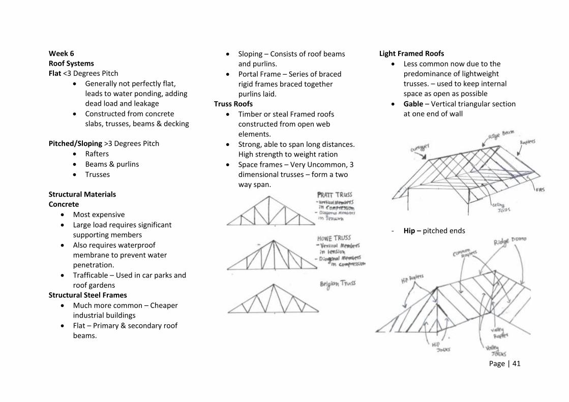
Truss Roofs
Timber or steal Framed roofs constructed from open web elements.
Strong, able to span long distances. High strength to weight ration
Space frames – Very Uncommon, 3 dimensional trusses – form a two way span.
Light Framed Roofs
Less common now due to the predominance of lightweight trusses. – used to keep internal space as open as possible
Gable – Vertical triangular section at one end of wall
- Hip – pitched ends
Page | 42
Cladding
Tiles, pitch > 15 degrees
Sheet metal pitch > 3 Degrees Spanning Spaces
The main technical challenge in building.
In Stone, beams or slabs. Corbels (overlapping stones tapering to a point). Neither can span a large space.
Arches- Can span space as a vault. Fail by deforming, not an issue when built into walls, very strong. Difficult to build because arches require supporting while under construction.
Column Grid, first method that was used to span large spaces, Hittite culture.
Romans later used arches to span large spaces, had the advantage of concrete.
Metals
Different metals used throughout different historical periods. Pre & post-industrial eras.
Are malleable, ductile and non – brittle.
Good Conductors. Has useful applications (wiring) but makes them point of weakness in terms temperature insulation of buildings. Window frames – cold bridges
High embodied energy but also quite recyclable
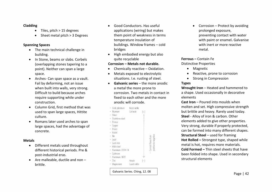
Corrosion – Metals not durable.
Chemically reactive – Oxidation.
Metals exposed to electrolytic situations. I.e. rusting of steel.
Galvanic series – the more anodic a metal the more prone to corrosion. Two metals in contact in fixed to each other and the more anodic will corrode.
Corrosion – Protect by avoiding prolonged exposure, preventing contact with water with paint or enamel. Galvanise with inert or more reactive metal.
Ferrous – Contain Fe Distinctive Properties
Magnetic
Reactive, prone to corrosion
Strong in Compression Types Wrought Iron – Heated and hammered to a shape. Used occasionally in decorative elements Cast Iron – Poured into moulds when molten and set. High compressive strength but brittle and heavy. Rarely used today. Steel - Alloy of iron & carbon. Other elements added to give other properties. Very strong, durable if properly protected, can be formed into many different shapes. Structural Steel – used for framing Hot Rolled – Strongest type, shaped while metal is hot, requires more materials. Cold Formed – Thin steel sheets that have been folded into shape. Used in secondary structural elements
Galvanic Series. Ching, 12. 08
Page | 43
Reinforcing bars - Bars set into concrete to produce reinforced concrete. Rough edges allow them to bond to concrete better.
1. Steel Sheeting – Used in cladding and roofing. Must be protected from corrosion
2. Stainless steel - Chromium is added to steel alloy making it more resistant to corrosion. Very rarely used due to prohibitive cost. Used in corrosive environments such as kitchens or hear the ocean.
Non Ferrous – Do not contain Fe Aluminium – Distinctive properties. Lightest metal, non-magnetic, easily shaped, Very expensive and high embodied energy. Used in window frames or fixtures. Can be used as a cladding. Naturally reacts with air to create protective oxide coating Copper – Disting properties. Excellent conductor, very malleable and ductile, distinct colour (salmon corrodes to green) Traditionally used in roofing. Still used in wiring and piping
Zinc – A thin layer is applied to steel element, known as galvanising, to protect them from corrosion. Less commonly used as a cladding Lead – No longer used commonly as it can cause lead poisoning in ingested. Tin - Rarely used today. Decorative elements or as a corrosion protection for roof cladding. Titanium – occasionally used as a cladding material as it is light, has a high strength to weight ration and has excellent corrosion resistance. It is prohibitively expensive however. Alloys – A mixture of at least two metals. Bronze – Copper & Tin. Used historically in external applications but has largely been superseded by aluminium. Brass – Copper + Zinc. Easy to work. Used In small fixings such as taps or screws.
Page | 44
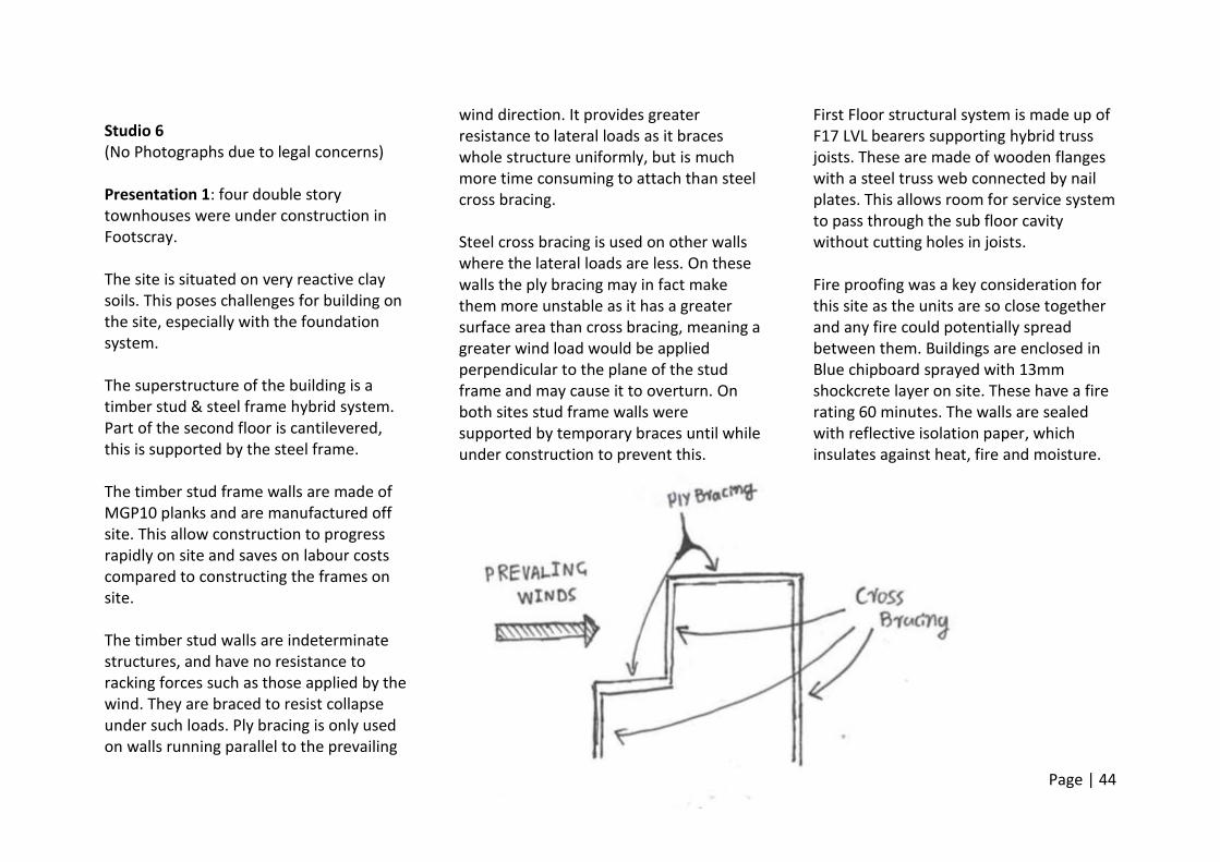
Studio 6 (No Photographs due to legal concerns) Presentation 1: four double story townhouses were under construction in Footscray. The site is situated on very reactive clay soils. This poses challenges for building on the site, especially with the foundation system. The superstructure of the building is a timber stud & steel frame hybrid system. Part of the second floor is cantilevered, this is supported by the steel frame. The timber stud frame walls are made of MGP10 planks and are manufactured off site. This allow construction to progress rapidly on site and saves on labour costs compared to constructing the frames on site. The timber stud walls are indeterminate structures, and have no resistance to racking forces such as those applied by the wind. They are braced to resist collapse under such loads. Ply bracing is only used on walls running parallel to the prevailing
wind direction. It provides greater resistance to lateral loads as it braces whole structure uniformly, but is much more time consuming to attach than steel cross bracing. Steel cross bracing is used on other walls where the lateral loads are less. On these walls the ply bracing may in fact make them more unstable as it has a greater surface area than cross bracing, meaning a greater wind load would be applied perpendicular to the plane of the stud frame and may cause it to overturn. On both sites stud frame walls were supported by temporary braces until while under construction to prevent this.
First Floor structural system is made up of F17 LVL bearers supporting hybrid truss joists. These are made of wooden flanges with a steel truss web connected by nail plates. This allows room for service system to pass through the sub floor cavity without cutting holes in joists. Fire proofing was a key consideration for this site as the units are so close together and any fire could potentially spread between them. Buildings are enclosed in Blue chipboard sprayed with 13mm shockcrete layer on site. These have a fire rating 60 minutes. The walls are sealed with reflective isolation paper, which insulates against heat, fire and moisture.
Page | 45
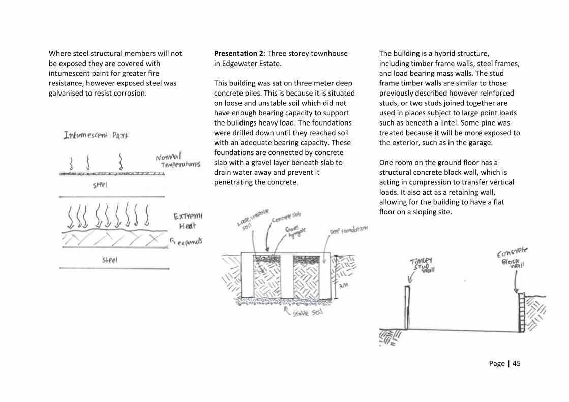
Where steel structural members will not be exposed they are covered with intumescent paint for greater fire resistance, however exposed steel was galvanised to resist corrosion.
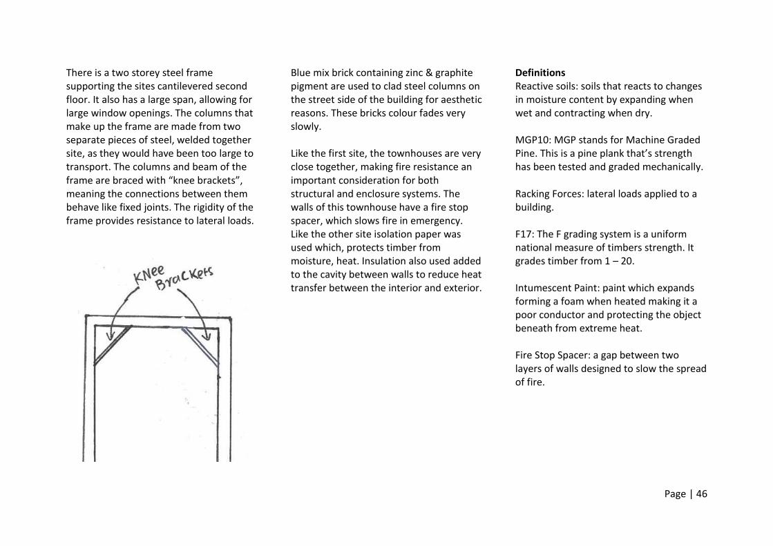
Presentation 2: Three storey townhouse in Edgewater Estate. This building was sat on three meter deep concrete piles. This is because it is situated on loose and unstable soil which did not have enough bearing capacity to support the buildings heavy load. The foundations were drilled down until they reached soil with an adequate bearing capacity. These foundations are connected by concrete slab with a gravel layer beneath slab to drain water away and prevent it penetrating the concrete.
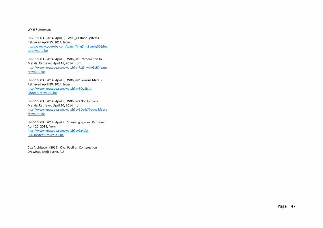
The building is a hybrid structure, including timber frame walls, steel frames, and load bearing mass walls. The stud frame timber walls are similar to those previously described however reinforced studs, or two studs joined together are used in places subject to large point loads such as beneath a lintel. Some pine was treated because it will be more exposed to the exterior, such as in the garage. One room on the ground floor has a structural concrete block wall, which is acting in compression to transfer vertical loads. It also act as a retaining wall, allowing for the building to have a flat floor on a sloping site.
Page | 46
There is a two storey steel frame supporting the sites cantilevered second floor. It also has a large span, allowing for large window openings. The columns that make up the frame are made from two separate pieces of steel, welded together site, as they would have been too large to transport. The columns and beam of the frame are braced with “knee brackets”, meaning the connections between them behave like fixed joints. The rigidity of the frame provides resistance to lateral loads.
Blue mix brick containing zinc & graphite pigment are used to clad steel columns on the street side of the building for aesthetic reasons. These bricks colour fades very slowly. Like the first site, the townhouses are very close together, making fire resistance an important consideration for both structural and enclosure systems. The walls of this townhouse have a fire stop spacer, which slows fire in emergency. Like the other site isolation paper was used which, protects timber from moisture, heat. Insulation also used added to the cavity between walls to reduce heat transfer between the interior and exterior.
Definitions Reactive soils: soils that reacts to changes in moisture content by expanding when wet and contracting when dry. MGP10: MGP stands for Machine Graded Pine. This is a pine plank that’s strength has been tested and graded mechanically. Racking Forces: lateral loads applied to a building. F17: The F grading system is a uniform national measure of timbers strength. It grades timber from 1 – 20. Intumescent Paint: paint which expands forming a foam when heated making it a poor conductor and protecting the object beneath from extreme heat. Fire Stop Spacer: a gap between two layers of walls designed to slow the spread of fire.
Page | 47
Wk 6 References ENVS10003. (2014, April 9). W06_c1 Roof Systems. Retrieved April 15, 2014, from https://www.youtube.com/watch?v=q5ms8vmhs50&feature=youtu.be ENVS10003. (2014, April 9). W06_m1 Introduction to Metals. Retrieved April 15, 2014, from http://www.youtube.com/watch?v=RttS_wgXGbI&feature=youtu.be ENVS10003. (2014, April 9). W06_m2 Ferrous Metals. Retrieved April 20, 2014, from http://www.youtube.com/watch?v=SQy3IyJy-is&feature=youtu.be ENVS10003. (2014, April 9). W06_m3 Non Ferrous Metals. Retrieved April 20, 2014, from http://www.youtube.com/watch?v=EDtxb7Pgcrw&feature=youtu.be ENVS10003. (2014, April 9). Spanning Spaces. Retrieved April 20, 2014, from http://www.youtube.com/watch?v=Zx4tM-uSaO8&feature=youtu.be Cox Architects. (2012). Oval Pavilion Construction Drawings. Melbourne, AU
Page | 48
Week 7 Curved forms Arches
Curved structures that span an opening. They are designed to support a vertical load by transforming it into inclined components and transmit them by compression to supporting abutments.
Arches can be made of wedge shaped masonry blocks or curved rigid members. (illustrate)
Elongated arches are known as vaults
Domes
Spherical surface structures constructed from stacked blocks or a continuous rigid material.
Supports vertical loads by acting in compression near the crown and tension near the base (illustrate)
A tension ring generally exists around the bottom of domes to prevent outwards movement.
Shells
Thin curved plate structures that transfer compressive and tensile
stresses along the plane of their surfaces. They can support large, uniformly applied forces but not concentrated or point loads due to their thinness.
3 kinds. translational (sliding a curve along a plane or curve), rotational, (rotating a curve about an axis) or ruled (generated by the motion of a straight line)
Vaults. Arch translated in a straight line. Behaves like an arch if length < 3x span. Behaves like a deep beam if Length > 3x span
Plastics
Produced by chemical processes. Monomers to polymers (hydrocarbons or silicates).
Properties vary greatly. Generally flexible, lightweight, waterproof and poor conductors. Can be durable & very cost effective. Some can be recycled, but derived from non-renewable petrochemicals.
Thermoplastics Mouldable when heated solidify when cooled. Recyclable.
PVC – used in piping, very cheap but environmentally harmful. Polycarbonate – can be used as a cladding Perspex – used as a substitute for glass as it does not shatter. Thermosetting plastics
Can only be shaped once, less recyclable
Laminex – used in finishing due to its lack of reactivity.
Rubber
Either manufactured from the sap of rubber trees or artificial rubber, an elastomer plastic with very similar properties to rubber manufactured chemically.
Properties, highly elastic, waterproof & poor conductor. Can be recyclable, cost effective. Embodied energy is small for natural rubber but greater for artificial.
Uses. – sealant, insulation, hosing
Deteriorated when exposed to the sun.
Page | 49
Paints
Liquid applied to a surface forming a thin skin which solidifies. Add colour and protect elements.
Clear paints are known as lacquers or varnishes
Water Based
Most common today. Durable, easier and safer to work as they are water soluble. brushes can be cleaned in water
Oil Based
More common historically. Can attain high gloss finishes, less safe and easy to use as they are not water soluble and must be cleaned with turpentine.
Properties
Vary greatly. Red paints tend to fade quicker in the sunlight. Durability varies with paint but also surface to which it is applied.
Detailing for moisture Excluding water
Can penetrate anywhere there is 1. An opening, 2. Water present at the opening 3. A force to move it through the opening.
Removing any one of these will prevent water penetration. Removing two or more is preferable in case one fails.
Removing openings
Walls often contain a vapour barrier, a membrane that prevents water from passing from one side to the other. A common example of this is sizilation.
Sealants or gaskets (preformed rubber shapes) used. These deteriorate and must be re – applied.
Keeping water from openings.
Roofs are sloped so that rainwater is discharged into gutter and downpipes then directed away from the building. Downpipes are usually external as there is less risk if they fail or become blocked. Eves protect walls from water that would run straight down them and pool at the base
Overlapping cladding elements protects joints from water.
Neutralising forces.
Gravity – flashing (cavity between walls, above windows), sills, paving. All slope away from building.
Page | 50
Surface tension – drips or breaks between surfaces used to prevent water creeping through gaps in joints by surface tension or capillary action
o Wind action – can push water
though simple gaps. Often constructed in complex shapes that slow water momentum and cause it to drain towards the outside of the building.
Air pressure – gusts of wind can cause air on the outside of a building to be at a higher pressure than that on the inside. Water “pumped” from high to low pressures. Seal placed on the internal side of gap to create a pressure chamber preventing this.
Basements
in wet areas need to be “tanked” wrapped in a waterproof membrane, typically artificial rubber
Dry areas. An “agricultural drain” can be installed. Slotted pipe near base of wall which water drains into through a coarse aggregate. Carries water away from site
Detailing for Heat
Controlling heat loss and gain saves energy, money and increase comfort for occupants.
Conducted though the building envelope. Three strategies used to prevent this, Thermal Insulation, Thermal beaks (gaps between highly conductive materials), Double glazing.
Radiation heat loss/gain. Prevented by using reflective/light coloured surfaces. Absorb less energy. spading buildings surfaces, preventing direct solar radiation.
Thermal mass. Materials that store heat and release it slowly. Used in climates where there is a large temperature difference between day and night. Heat absorbed during the day released at night. keeps the building warm. Concrete, stone and masonry known for their thermal mass
Preventing air leakage. Very similar to preventing water leakage. (3 conditions needed for leakage etc.) Prevents warm/cool air being lost.
Page | 51
Wk 07 References ENVS10003. (2014, April 16). Detailing for Heat and Moisture. Retrieved April 22, 2014, from http://www.youtube.com/watch?v=Lhwm8m5R_Co&feature=youtu.be ENVS10003. (2014, April 16). W07_m2 Plastics. Retrieved April 22, 2014 from http://www.youtube.com/watch?v=5pfnCtUOfy4&feature=youtu.be ENVS10003. (2014, April 16). W07_m1 Rubber. Retrieved April 22, 2014 from http://www.youtube.com/watch?v=OPhjDijdf6I&feature=youtu.be ENVS10003. (2014, April 16). W07_m3 Paints. Retrieved April 22, 2014 from https://www.youtube.com/watch?v=WrydR4LA5e0&feature=youtu.be Ching, F. (2008) Building Construction Illustrated (4th Ed.). Hoboken, NJ: John Wiley & Sons.
Page | 52
Week 8
Openings Important to how we use buildings
(function) and also how they appear (composition)
Allow light & ventilation, access, contribute views &architectural character.
Structures must be designed to transfer load around openings.
Fly screens sometimes added to allow ventilation but exclude insects
Frame materials
Aluminium – lightweight, poor insulator - forms Heat Bridge thermal breaks often used to combat this, high embodied energy, corrosion resistant.
Wood -
Steel – Durable & resistant to physical damage. Expensive. Often used for bespoke designs.
Curtain Walls
Hybrid system, repeating window units that make the walling system of a building.
Hung directly from the buildings primary structure.
Carry their own load
Doors
Styles - Swinging, Sliding, folding
Made of a range of materials, n including timber, aluminium, steel
Terminology (https://www.youtube.com/watch?v=g7QQIue58xY&feature=youtu.be)
(Ching, 8.04)
Page | 53
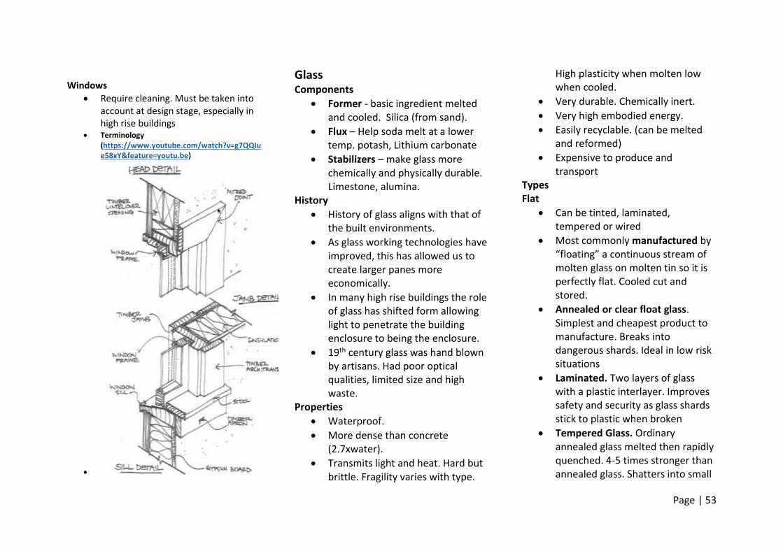
Windows
Require cleaning. Must be taken into account at design stage, especially in high rise buildings
Terminology (https://www.youtube.com/watch?v=g7QQIue58xY&feature=youtu.be)
Glass
Components
Former - basic ingredient melted and cooled. Silica (from sand).
Flux – Help soda melt at a lower temp. potash, Lithium carbonate
Stabilizers – make glass more chemically and physically durable. Limestone, alumina.
History
History of glass aligns with that of the built environments.
As glass working technologies have improved, this has allowed us to create larger panes more economically.
In many high rise buildings the role of glass has shifted form allowing light to penetrate the building enclosure to being the enclosure.
19th century glass was hand blown by artisans. Had poor optical qualities, limited size and high waste.
Properties
Waterproof.
More dense than concrete (2.7xwater).
Transmits light and heat. Hard but brittle. Fragility varies with type.
High plasticity when molten low when cooled.
Very durable. Chemically inert.
Very high embodied energy.
Easily recyclable. (can be melted and reformed)
Expensive to produce and transport
Types Flat
Can be tinted, laminated, tempered or wired
Most commonly manufactured by “floating” a continuous stream of molten glass on molten tin so it is perfectly flat. Cooled cut and stored.
Annealed or clear float glass. Simplest and cheapest product to manufacture. Breaks into dangerous shards. Ideal in low risk situations
Laminated. Two layers of glass with a plastic interlayer. Improves safety and security as glass shards stick to plastic when broken
Tempered Glass. Ordinary annealed glass melted then rapidly quenched. 4-5 times stronger than annealed glass. Shatters into small
Page | 54
pieces rather than shards. Ideal in exposed areas (glass balustrades or facades. if the surface of glass is broken in one place the whole pane shatters as the surface is in tension.
Can be tinted to reduce light transfer, wired as an alternative to lamination, Patterned for opacity to allow privacy or have Photovoltaic cells integrated.
Shaped
Curved, blocks, tubes Double/Triple Glazing
Heat transfer through windows is problematic in winter and summer.
Layer of air between two panes of glass improves insulating properties by reducing conduction
More effective in preventing ambient heat loss in winter but less effective in preventing heat gains due to radiation in summer
Structural Forces
Moment of Inertia: I = MR^2 where I = moment of inertia, M = Mass of object, R = distance of mass from rotation axis.
It is a measure of an objects rotational inertial, or how difficult it is to rotate. The higher an objects moment of inertia the more difficult it is to rotate
Objects with mass further from their rotational axis have a higher moment of inertia.
Deformation
Buckling – see columns
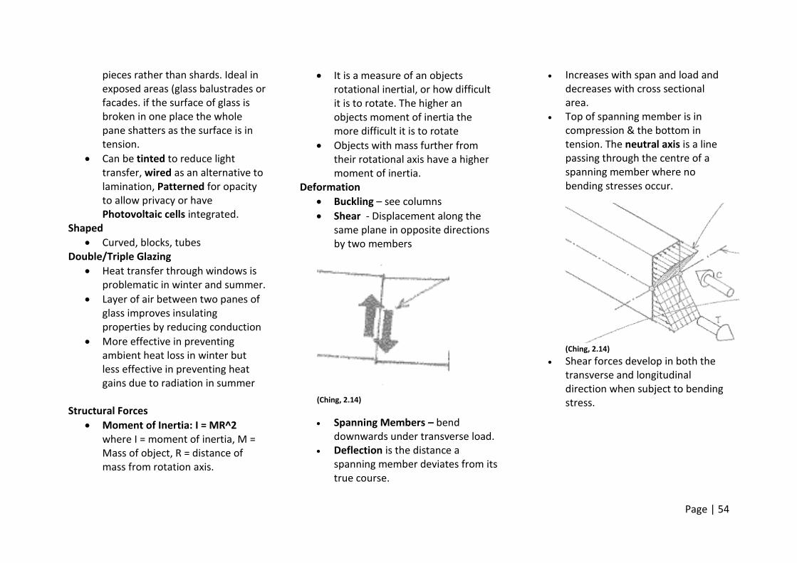
Shear - Displacement along the same plane in opposite directions by two members
(Ching, 2.14)
Spanning Members – bend downwards under transverse load.
Deflection is the distance a spanning member deviates from its true course.
Increases with span and load and decreases with cross sectional area.
Top of spanning member is in compression & the bottom in tension. The neutral axis is a line passing through the centre of a spanning member where no bending stresses occur.
(Ching, 2.14)
Shear forces develop in both the transverse and longitudinal direction when subject to bending stress.
Page | 55
Wk 8 References ENVI10003. (2014, April 3). W08_c1 OPENINGS: DOORS & WINDOWS. Retrieved May 3, 2014, from https://www.youtube.com/watch?v=g7QQIue58xY&feature=youtu.be ENVI10003. (2014, April 3). GLASS SKINS. Retrieved May 3, 2014, from https://www.youtube.com/watch?v=NW_GibnyBZc&feature=youtu.be ENVI10003. (2014, April 3). W08_m1 Glass. Retrieved May 3, 2014, from https://www.youtube.com/watch?v=_I0Jqcrfcyk&feature=youtu.be Ching, F. (2008) Building Construction Illustrated (4th Ed.). Hoboken, NJ: John Wiley & Sons.
Page | 56
Week 9
Composite Materials
Two or more materials combined in such a way that the properties of individual materials are still distinguishable.
Combination of materials that differ in composition that are bonded together.
retaining their individual identities and properties but act together to improve specific synergistic characteristics not obtainable by either original material alone
Types Fibrous – contain discontinuous fibres Laminar – layers of different materials (yellow core MDF or sandwich panels) Particulate – Particles bonded together (gravel in resin) Hybrid – Two or more types of composite material Examples Fibre reinforced Cement (FRC)
Made from Glass fibre, cement, sand and water.
Found In Sheets or shaped products such as roof tiles
Used in exterior cladding, interior wet areas and under tiles
Does not burn, resistant to water and termite damage. Resistant to rotting and warping, inexpensive
Fibreglass
Made from glass fibres and epoxy resin.
Flat or profiled sheet products.
Translucent cladding or pre – formed shaped water holding products.
Fire resistant, weatherproof, lightweight and strong
Aluminium Sheet Composite “sandwich panel”
Aluminium sheet skins on plastic honeycomb core
Feature cladding material
Reduces amount of aluminium used to achieve same effect, lighter weight, less expensive. Weather resistant, shock resistant and very durable. Can be folded or fitted into window frames to achieve seamless finishes
Timber Composites
Structural beams. Timber top and bottom cords with steel, or engineered timber webs.
Used in beams and trusses
Materially efficient, cost effective, easy to install and accommodate services.
Fibre Reinforced Polymer
Polymers reinforced by glass/timber/carbon fibres.
Moulded products
Used externally as cladding, or in exposed structural elements
Extremely high strength to weight ratio (greater than steel). Corrosion resistant
Construction Detailing
Principals to consider Movement Joints
Allow for movement due to thermal expansion/contraction or differential soil movement. Prevents building from cracking.
Should provide separation between materials and allow for free movement while maintaining weather tightness
Filled with sealants such as caulking of foam.
3 types 1. Expansion joints – continuous
unobstructed slots between two parts of a building that allow for expansion
2. Control joints – grooves in concrete that form a plane of weakness, regulating the location of cracking from
Page | 57
drying shrinkage or other movement
3. Isolation Joints – divide a structure into sections to allow for differential settlement
Used in brick walls at openings or any change in direction.
Structural Joints
The structural requirements of connecting two element can affect the finished detail.
Bolts heads may leave lumps, however details can be designed to avid this (recessing, countersunk cap screws)
If structural connections are to be exposed aesthetics should be taken into consideration when detailing (ie consider connecting wood with a moulded joint rather than nail plates)
Health and safety
Building codes specify detailing for safety ie
balustrades and stairs
Material selection limited in wet areas
Fire resistant materials. Different sizes and occupancies require different levels of fire resistance
Tumescent paint. Expands when heated insulating material against heat
Disabled access also required
Aging
Material/coatings need to be selected appropriately for buildings location or use. Buildings in harsh areas (marine or industrial) age quicker.
Matte finishes age better than glossy ones (lose finish), with the exception of enamelled/glazed form
Some materials improve with age (copper, some woods)
Reparability
Materials should be able to be replaced/repaired easily
Detailing can improve damage resistance. Ie skirting protects walls.
Corners are also vulnerable Cleanablilty
Important in restaurants/hospitals
Corners difficult to clean, trap dirt. Rounded or “coved” corners useful
Constuctability
The more difficult to construct = more expensive
3 general principals. 1 easy to assemble (ie use off the shelf products, ones there is the local expertise in using, and that are easy to assemble), 2 forgiving of minor errors, 3 efficient use of facilities/labour
Finish Work
Materials used to finish interior surfaces.
should be wear resistant, cleanable and have desirable aesthetics
Acoustic performance, fire resistance and thermal insulation should also be considered.
Surface materials include plasterboard, gypsum board, wood veneer, and plastic laminate
Baseboards conceal the joint between floor and wall and cornices do conceal the joint between roof and walls
Page | 58
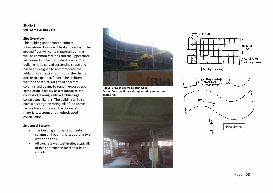
Studio 9 Off- Campus site visit Site Overview The building under construction at International House will be 4 storeys high. The ground floor will contain tutorial rooms as well as common facilities and the upper three will house flats for graduate students. The building has a curved serpentine shape and has been designed to accommodate the addition of an extra floor should the clients decide to expand in future. The architect wanted the structural grid of concrete columns and beams to remain exposed upon completion, partially as a response to the context of sharing a site with buildings constructed like this. The building will also have a 5 star green rating. All of the above factors have influenced the choice of materials, systems and methods used in construction. Structural System
The building employs a concrete column and beam grid supporting two way floor slabs.
All concrete was cast in situ, atypically of this construction method it has a class A finish.
Above: View of site from south west. Below: Concrete floor slab supported by column and beam grid.
Plan Sketch
Page | 59
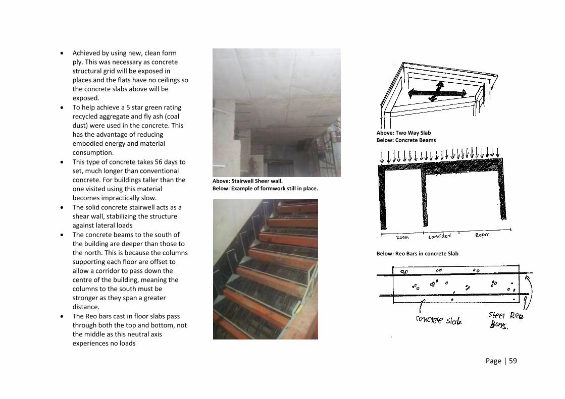
Achieved by using new, clean form ply. This was necessary as concrete structural grid will be exposed in places and the flats have no ceilings so the concrete slabs above will be exposed.
To help achieve a 5 star green rating recycled aggregate and fly ash (coal dust) were used in the concrete. This has the advantage of reducing embodied energy and material consumption.
This type of concrete takes 56 days to set, much longer than conventional concrete. For buildings taller than the one visited using this material becomes impractically slow.
The solid concrete stairwell acts as a shear wall, stabilizing the structure against lateral loads
The concrete beams to the south of the building are deeper than those to the north. This is because the columns supporting each floor are offset to allow a corridor to pass down the centre of the building, meaning the columns to the south must be stronger as they span a greater distance.
The Reo bars cast in floor slabs pass through both the top and bottom, not the middle as this neutral axis experiences no loads
Above: Stairwell Sheer wall. Below: Example of formwork still in place.
Above: Two Way Slab Below: Concrete Beams
Below: Reo Bars in concrete Slab
Page | 60
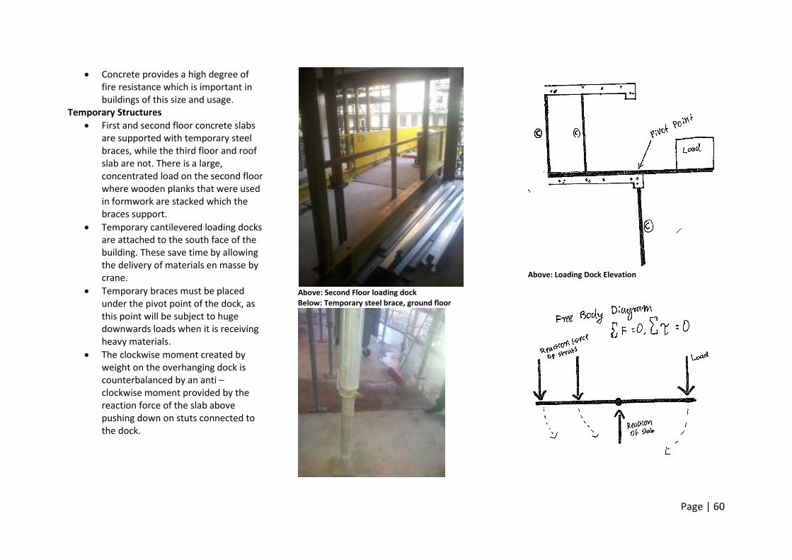
Concrete provides a high degree of fire resistance which is important in buildings of this size and usage.
Temporary Structures
First and second floor concrete slabs are supported with temporary steel braces, while the third floor and roof slab are not. There is a large, concentrated load on the second floor where wooden planks that were used in formwork are stacked which the braces support.
Temporary cantilevered loading docks are attached to the south face of the building. These save time by allowing the delivery of materials en masse by crane.
Temporary braces must be placed under the pivot point of the dock, as this point will be subject to huge downwards loads when it is receiving heavy materials.
The clockwise moment created by weight on the overhanging dock is counterbalanced by an anti – clockwise moment provided by the reaction force of the slab above pushing down on stuts connected to the dock.
Above: Second Floor loading dock Below: Temporary steel brace, ground floor
Above: Loading Dock Elevation
Page | 61
Enclosure System
Much of the buildings skin on the north/south walls will be glass, which has yet to be delivered to site.
Double glazing and aluminium window frames with a thermal break will be used to reduce heat transfer through the skin
Most elevations will also be covered by exterior perforated galvanised steel sun shading to protect from direct summer sun. Especially important on the north facing glass wall.
Glass skin allows direct sunlight onto concrete in winter, utilising its high thermal mass.
Enamelled white bricks have been installed as part of the buildings skin on the royal park side of the site. Match those used on a nearby building, and are also quite durable, as exemplified in that building which is over 10 years old and not showing signs of aging.
Internal walls
Internal dividing walls are made of non-structural light gauge steel stud frames.
A double stud wall is used in the gap between rooms to provide acoustic separation between rooms.
Are straight despite buildings shape to save cost.
Above: White enamelled brick skin and cantilevers to hang sun shades. Below: Double light gauge steel stud frame walls dividing flats
Page | 62
Service System
To allow for exposed concrete beams holes must be made in beams to allow the delivery of services through them, rather than beneath as would normally be the case.
This was achieved by placing polystyrene blocks in the formwork, which would create negative space in the beam when the concrete is cured and they are removed.
As the standard services found in a domestic building regulation also requires emergency sprinklers in a building of this size in case of fire.
As the exposed concrete slab will act as the ceiling in most flats services that are usually delivered through the ceiling cavity, such as wiring for lighting, are to be delivered through the gap between the double stud walls dividing rooms.
Another concession to allow for exposed concrete beams is the delivery of air conditioning ducts through the floor in ground floor tutorial rooms.
Water pipes are insulated with plastic to reduce heat loss as copper is a good conductor and water must be transported a long distance.
`
Above: hot/cold water and fire sprinkler services passing through holes cast in concrete beams.
Page | 63
Wk 9 References ENVS10003. (2014, May 7). W09_m1 Composite Materials. Retrieved May 8, 2014 from https://www.youtube.com/watch?v=Uem1_fBpjVQ&feature=youtu.be ENVS10003. (2014, May 7). W09_m1 Construction Detailing. Retrieved May 11, 2014 from https://www.youtube.com/watch?v=yqVwAV7yJCI&feature=youtu.be Ching, F. (2008) Building Construction Illustrated (4th Ed.). Hoboken, NJ: John Wiley & Sons.
Page | 64
Week 10 When things go wrong Galvanic Corrosion Metals at different ends of the galvanic series corrode when in contact. The statue of liberty. Copper skin supported by steel frame and ribs. Galvanic corrosion was considered, and the two were separated by a varnished asbestos cloth. Over time this became porous and held moisture, creating ideal conditions for galvanic corrosion. Thus iron was oxidised, expanding and potentially breaking the saddles holding the skin to the frame. Modern solution, replace iron armature with one coated in Teflon, as this will last for a long time. Continued monitoring is still required as the presence of two metals still leaves the potential for galvanic corrosion. Materials Environmental Considerations Adverse Health Effects.
Reduce VOC’s. Given off by oil based paints when drying, replace with water based ones. Also found in sealants and glues.
Minimise dust inhalation. Reduce horizontal shelves, carpets etc.
Choose materials that can be cleaned without chemicals.
Heros Villains
Materials that do not require a chemical finish Carpets Oil based paints Adhesives Treated pine.
Materials that require varnishing etc. Termite protection mesh.
Household Waste.
Economically and environmentally inefficient. Wastes limited resources and space.
Use Renewable resources, eg. Plantation or recycled timber instead of hardwoods. Grasses like bamboo that grow quicker than hardwoods.
Heros Villains
Bamboo Sustainable forestry Plantation timber Recycled materials
Old growth hardwoods Tiling (lot of offcuts)
Energy use and Embodied energy.
Drives Climate Change and produces pollution
Embodied energy: the amount of energy used to produce a product.
Including extraction, manufacture and transport.
Heros Villains
Timber Australian Products LEDs
Aluminium Incandescent lights
Pollution.
Smog, ozone depletion, eutrophication, acid rain.
Minimise waste, choose natural and organic materials
Heros Villains
Linoleum (as an alternative) Wool
PVC
Life Cycle.
How long it lasts and how it changes over time. Is it recyclable
Detailing Failures Consider: exposure, compatibility, strength and deflection, long term performance, workmanship, maintenance. Examples of failures
Thin materials painted black on one side warp in the sun, as one side as differential heating causes it to warp
Glues and sealants can fail under sunlight and heat, allowing water to penetrate buildings skin.
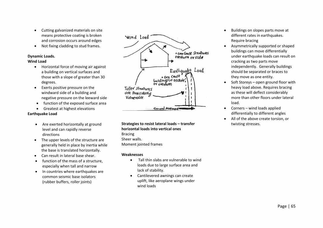
Page | 65
Cutting galvanized materials on site means protective coating is broken and corrosion occurs around edges
Not fixing cladding to stud frames. Dynamic Loads. Wind Load
Horizontal force of moving air against a building on vertical surfaces and those with a slope of greater than 30 degrees.
Exerts positive pressure on the windward side of a building and negative pressure on the leeward side
function of the exposed surface area
Greatest at highest elevations Earthquake Load
Are exerted horizontally at ground level and can rapidly reverse directions
The upper levels of the structure are generally held in place by inertia while the base is translated horizontally.
Can result in lateral base shear.
function of the mass of a structure, especially when tall and narrow
In countries where earthquakes are common seismic base isolators (rubber buffers, roller joints)
Strategies to resist lateral loads – transfer horizontal loads into vertical ones Bracing Sheer walls. Moment jointed frames Weaknesses
Tall thin slabs are vulnerable to wind loads due to large surface area and lack of stability.
Cantilevered awnings can create uplift, like aeroplane wings under wind loads
Buildings on slopes parts move at different rates in earthquakes. Require bracing
Asymmetrically supported or shaped buildings can move differentially under earthquake loads can result on cracking as two parts move independently. Generally buildings should be separated or braces to they move as one entity.
Soft Storeys – open ground floor with heavy load above. Requires bracing as these will deflect considerably more than other floors under lateral load.
Corners – wind loads applied differentially to different angles
All of the above create torsion, or twisting stresses.
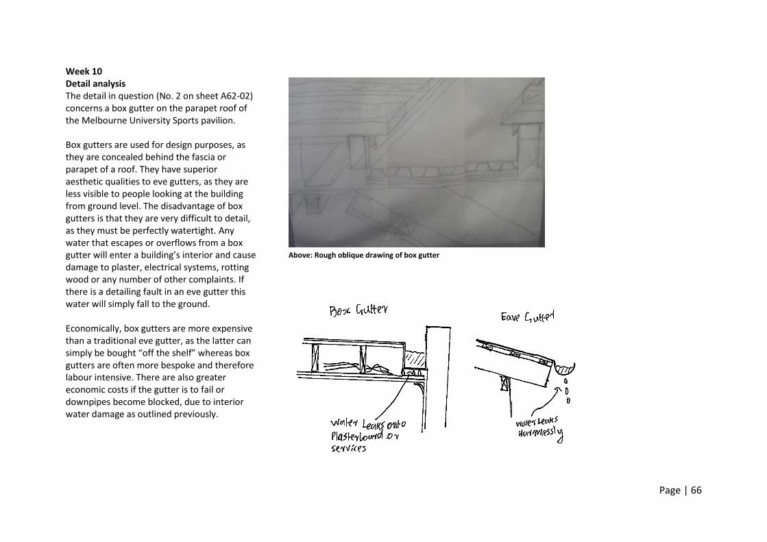
Page | 66
Week 10 Detail analysis The detail in question (No. 2 on sheet A62-02) concerns a box gutter on the parapet roof of the Melbourne University Sports pavilion. Box gutters are used for design purposes, as they are concealed behind the fascia or parapet of a roof. They have superior aesthetic qualities to eve gutters, as they are less visible to people looking at the building from ground level. The disadvantage of box gutters is that they are very difficult to detail, as they must be perfectly watertight. Any water that escapes or overflows from a box gutter will enter a building’s interior and cause damage to plaster, electrical systems, rotting wood or any number of other complaints. If there is a detailing fault in an eve gutter this water will simply fall to the ground. Economically, box gutters are more expensive than a traditional eve gutter, as the latter can simply be bought “off the shelf” whereas box gutters are often more bespoke and therefore labour intensive. There are also greater economic costs if the gutter is to fail or downpipes become blocked, due to interior water damage as outlined previously.
Above: Rough oblique drawing of box gutter
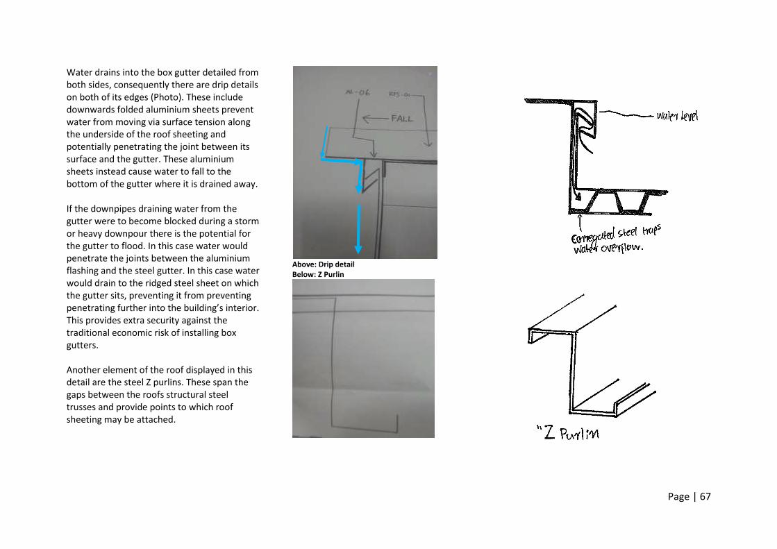
Page | 67
Water drains into the box gutter detailed from both sides, consequently there are drip details on both of its edges (Photo). These include downwards folded aluminium sheets prevent water from moving via surface tension along the underside of the roof sheeting and potentially penetrating the joint between its surface and the gutter. These aluminium sheets instead cause water to fall to the bottom of the gutter where it is drained away. If the downpipes draining water from the gutter were to become blocked during a storm or heavy downpour there is the potential for the gutter to flood. In this case water would penetrate the joints between the aluminium flashing and the steel gutter. In this case water would drain to the ridged steel sheet on which the gutter sits, preventing it from preventing penetrating further into the building’s interior. This provides extra security against the traditional economic risk of installing box gutters. Another element of the roof displayed in this detail are the steel Z purlins. These span the gaps between the roofs structural steel trusses and provide points to which roof sheeting may be attached.
Above: Drip detail Below: Z Purlin
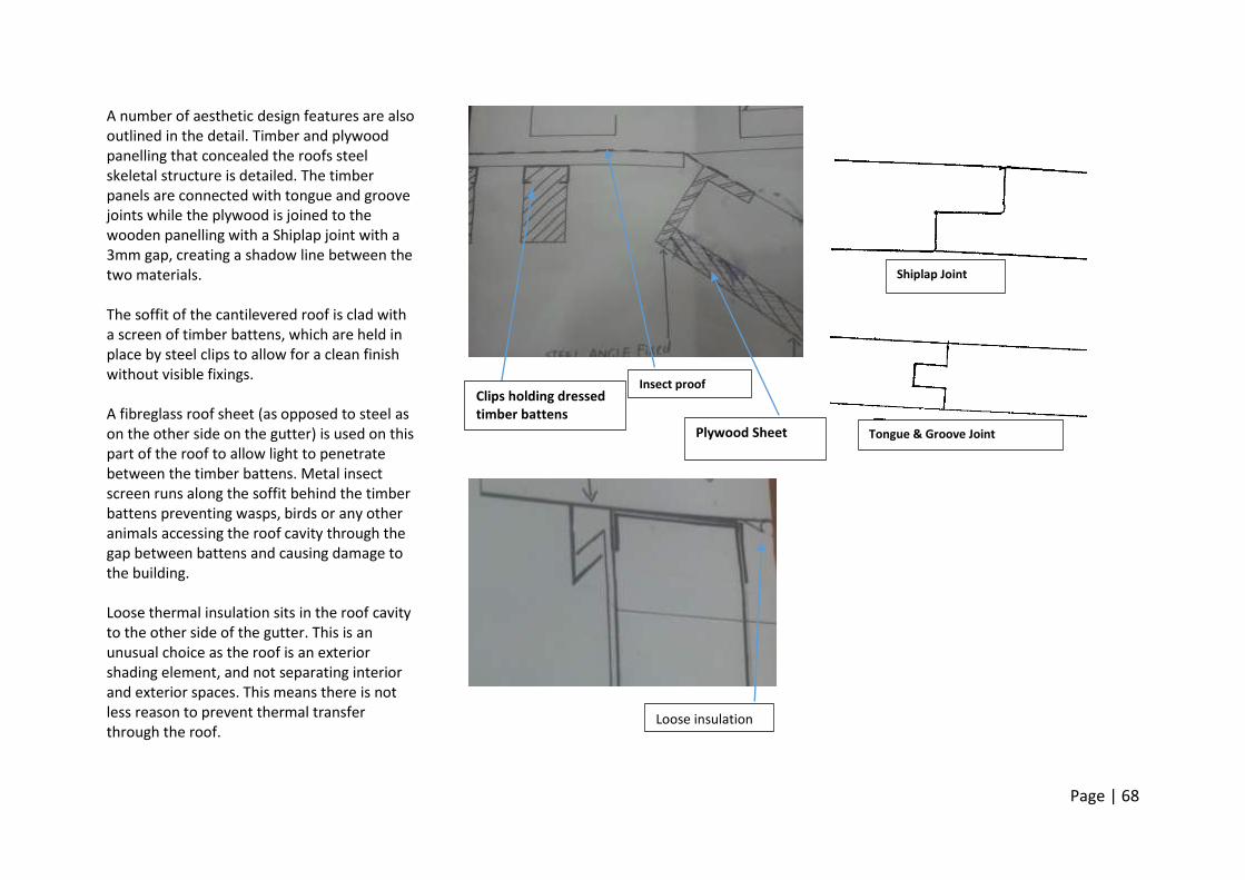
Page | 68
A number of aesthetic design features are also outlined in the detail. Timber and plywood panelling that concealed the roofs steel skeletal structure is detailed. The timber panels are connected with tongue and groove joints while the plywood is joined to the wooden panelling with a Shiplap joint with a 3mm gap, creating a shadow line between the two materials. The soffit of the cantilevered roof is clad with a screen of timber battens, which are held in place by steel clips to allow for a clean finish without visible fixings. A fibreglass roof sheet (as opposed to steel as on the other side on the gutter) is used on this part of the roof to allow light to penetrate between the timber battens. Metal insect screen runs along the soffit behind the timber battens preventing wasps, birds or any other animals accessing the roof cavity through the gap between battens and causing damage to the building. Loose thermal insulation sits in the roof cavity to the other side of the gutter. This is an unusual choice as the roof is an exterior shading element, and not separating interior and exterior spaces. This means there is not less reason to prevent thermal transfer through the roof.
Clips holding dressed timber battens
Plywood Sheet
Insect proof screen
Loose insulation
Shiplap Joint
Tongue & Groove Joint
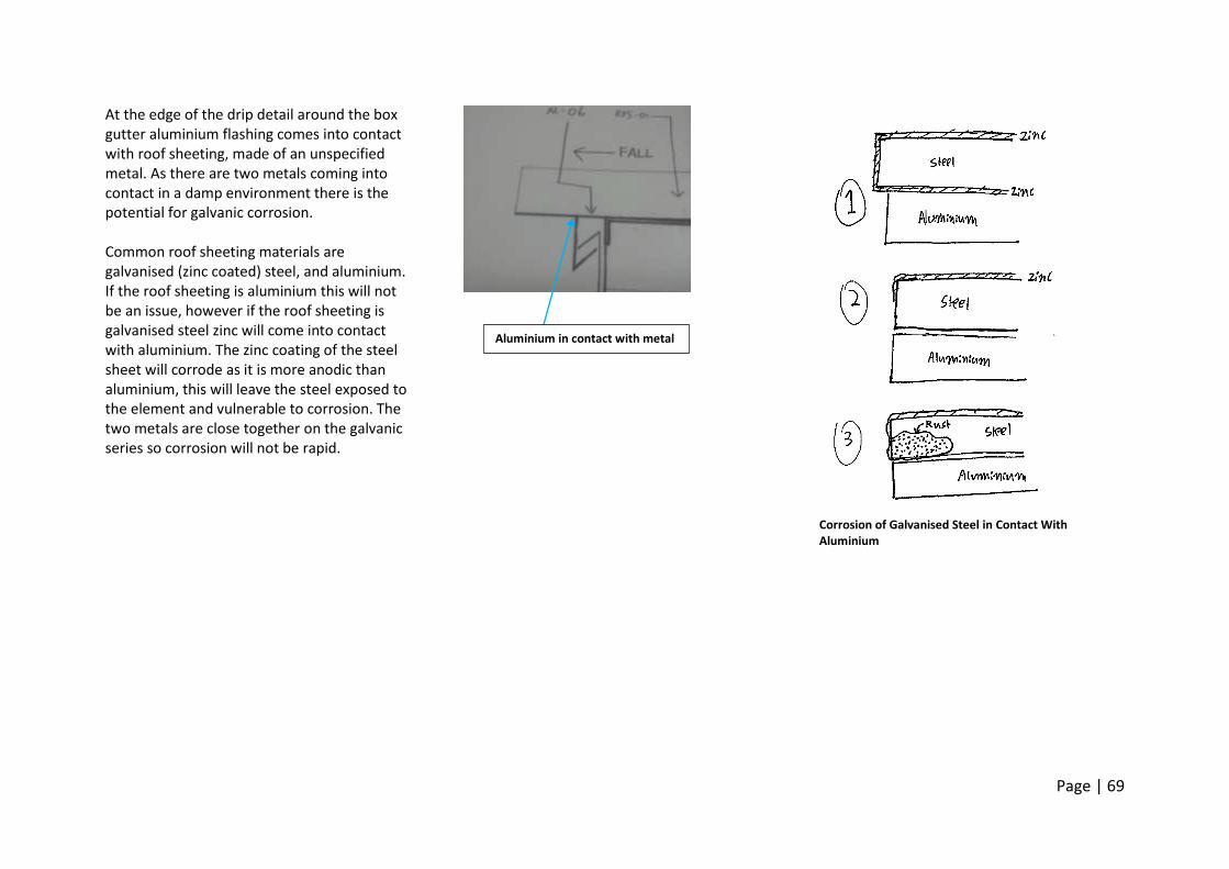
Page | 69
At the edge of the drip detail around the box gutter aluminium flashing comes into contact with roof sheeting, made of an unspecified metal. As there are two metals coming into contact in a damp environment there is the potential for galvanic corrosion. Common roof sheeting materials are galvanised (zinc coated) steel, and aluminium. If the roof sheeting is aluminium this will not be an issue, however if the roof sheeting is galvanised steel zinc will come into contact with aluminium. The zinc coating of the steel sheet will corrode as it is more anodic than aluminium, this will leave the steel exposed to the element and vulnerable to corrosion. The two metals are close together on the galvanic series so corrosion will not be rapid.
Corrosion of Galvanised Steel in Contact With Aluminium
Aluminium in contact with metal
Page | 70
WK 10 References ENVS10003. (2014, may 13) W10_m2 A Tale of Corrosion. Retrieved may 16, 2012 from https://www.youtube.com/watch?v=2IqhvAeDjlg&feature=youtu.be ENVS10003. (2014, may 13) W10_s1 Lateral Supports. Retrieved may 16, 2012 from https://www.youtube.com/watch?v=BodoWgcQapA ENVS10003. (2014, may 13). W10_m1 Heroes and Culprits. Retrieved may 16, 2012 from https://www.youtube.com/watch?v=FhdfwGNp_6g&feature=youtu.be ENVS10003. (2014, may 13) Collapses and Failures. Retrieved may 16, 2012 from https://www.youtube.com/watch?v=yNEl-fYRi_I&feature=youtu.be Ching, F. (2008) Building Construction Illustrated (4th Ed.). Hoboken, NJ: John Wiley & Sons.
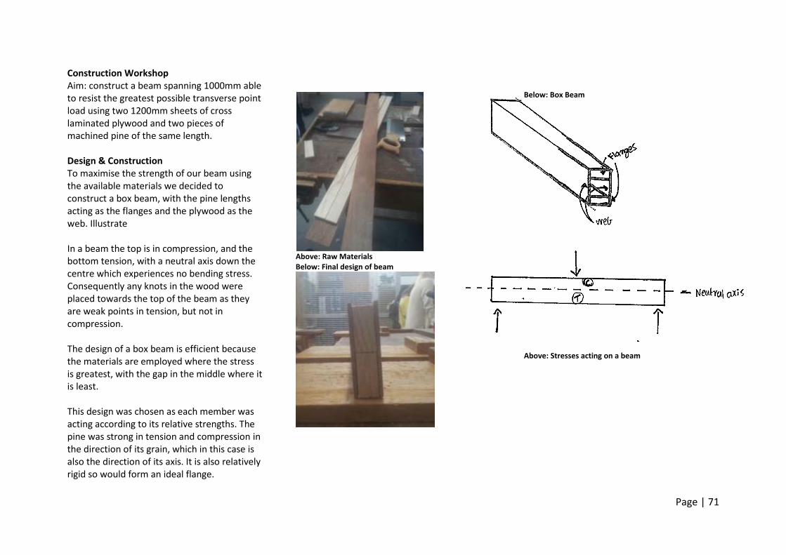
Page | 71
Construction Workshop Aim: construct a beam spanning 1000mm able to resist the greatest possible transverse point load using two 1200mm sheets of cross laminated plywood and two pieces of machined pine of the same length. Design & Construction To maximise the strength of our beam using the available materials we decided to construct a box beam, with the pine lengths acting as the flanges and the plywood as the web. Illustrate In a beam the top is in compression, and the bottom tension, with a neutral axis down the centre which experiences no bending stress. Consequently any knots in the wood were placed towards the top of the beam as they are weak points in tension, but not in compression. The design of a box beam is efficient because the materials are employed where the stress is greatest, with the gap in the middle where it is least. This design was chosen as each member was acting according to its relative strengths. The pine was strong in tension and compression in the direction of its grain, which in this case is also the direction of its axis. It is also relatively rigid so would form an ideal flange.
Above: Raw Materials Below: Final design of beam
Below: Box Beam
Above: Stresses acting on a beam
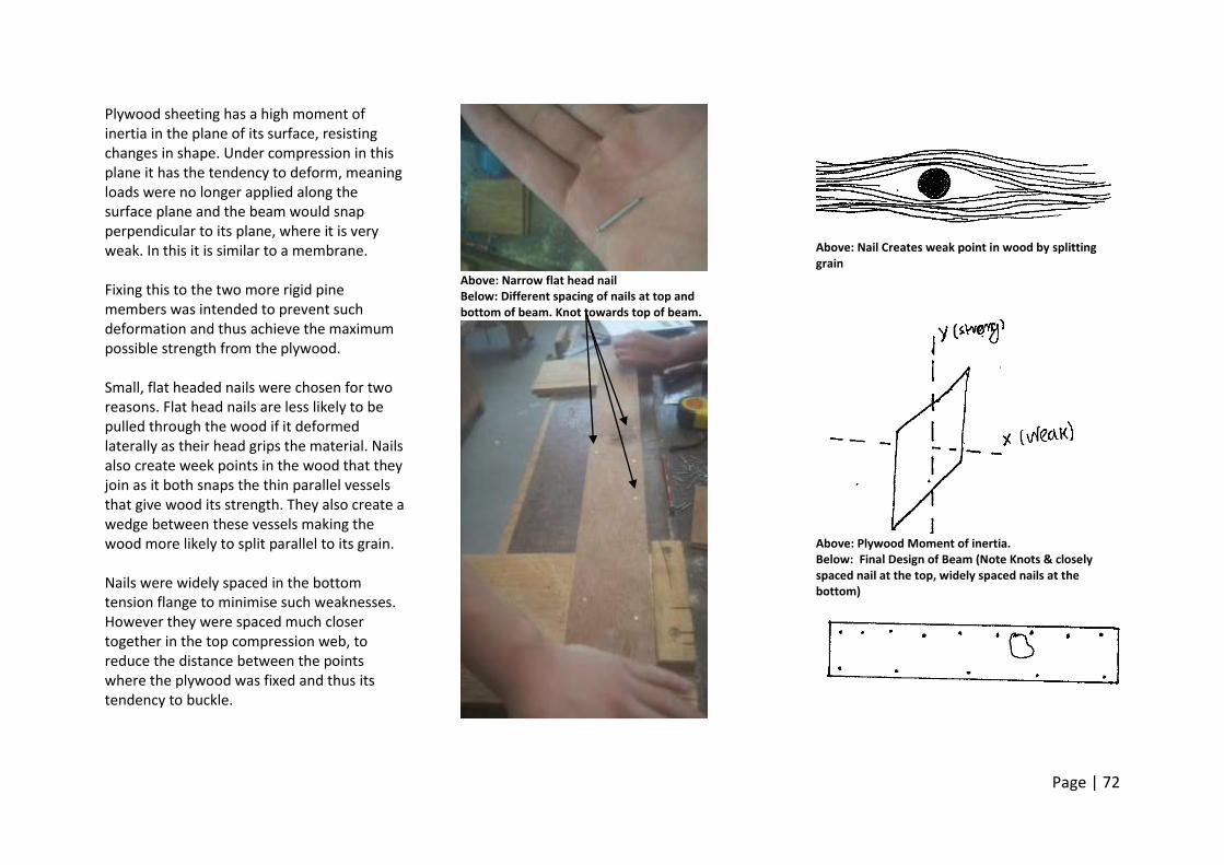
Page | 72
Plywood sheeting has a high moment of inertia in the plane of its surface, resisting changes in shape. Under compression in this plane it has the tendency to deform, meaning loads were no longer applied along the surface plane and the beam would snap perpendicular to its plane, where it is very weak. In this it is similar to a membrane. Fixing this to the two more rigid pine members was intended to prevent such deformation and thus achieve the maximum possible strength from the plywood. Small, flat headed nails were chosen for two reasons. Flat head nails are less likely to be pulled through the wood if it deformed laterally as their head grips the material. Nails also create week points in the wood that they join as it both snaps the thin parallel vessels that give wood its strength. They also create a wedge between these vessels making the wood more likely to split parallel to its grain. Nails were widely spaced in the bottom tension flange to minimise such weaknesses. However they were spaced much closer together in the top compression web, to reduce the distance between the points where the plywood was fixed and thus its tendency to buckle.
Above: Narrow flat head nail Below: Different spacing of nails at top and bottom of beam. Knot towards top of beam.
Above: Nail Creates weak point in wood by splitting grain
Above: Plywood Moment of inertia. Below: Final Design of Beam (Note Knots & closely spaced nail at the top, widely spaced nails at the bottom)
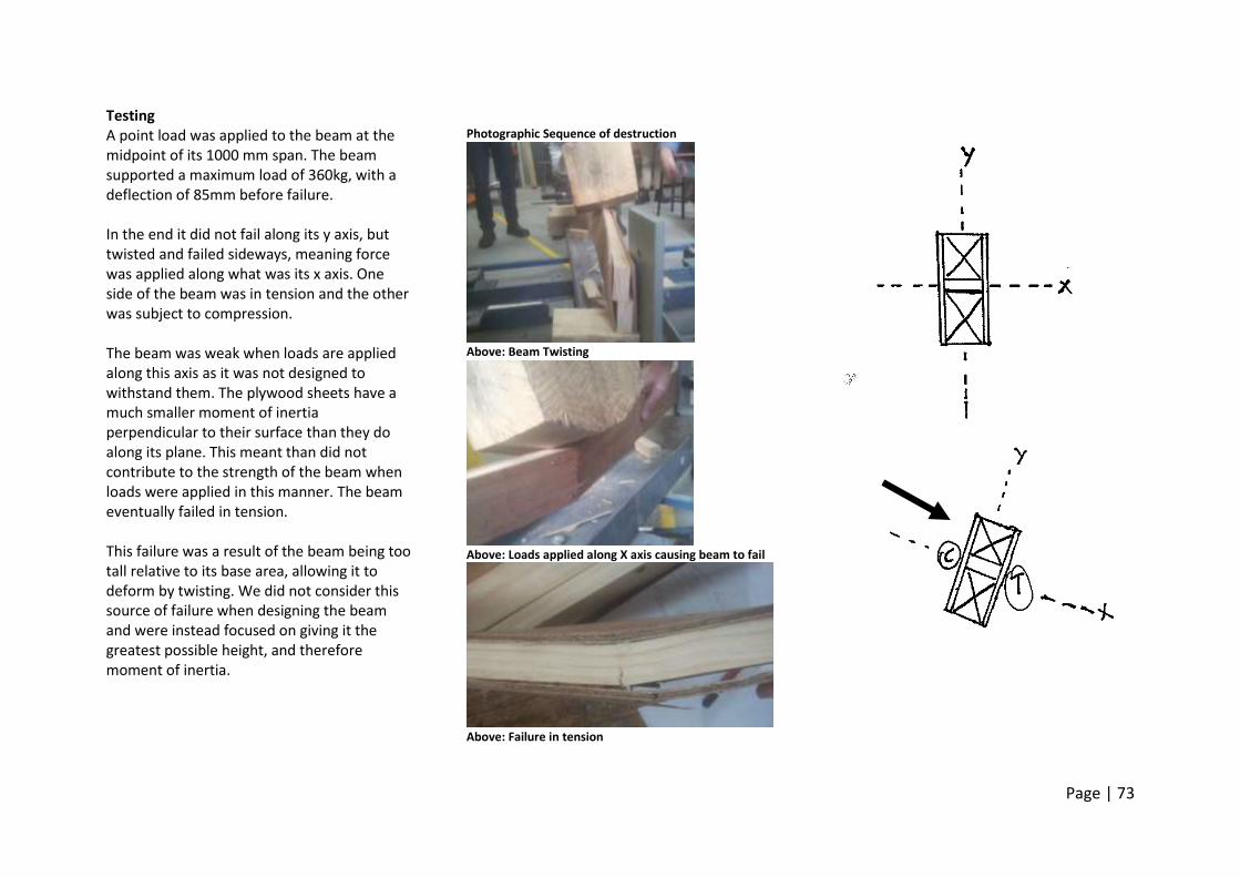
Page | 73
Testing A point load was applied to the beam at the midpoint of its 1000 mm span. The beam supported a maximum load of 360kg, with a deflection of 85mm before failure. In the end it did not fail along its y axis, but twisted and failed sideways, meaning force was applied along what was its x axis. One side of the beam was in tension and the other was subject to compression. The beam was weak when loads are applied along this axis as it was not designed to withstand them. The plywood sheets have a much smaller moment of inertia perpendicular to their surface than they do along its plane. This meant than did not contribute to the strength of the beam when loads were applied in this manner. The beam eventually failed in tension. This failure was a result of the beam being too tall relative to its base area, allowing it to deform by twisting. We did not consider this source of failure when designing the beam and were instead focused on giving it the greatest possible height, and therefore moment of inertia.
Photographic Sequence of destruction
Above: Beam Twisting
Above: Loads applied along X axis causing beam to fail
Above: Failure in tension
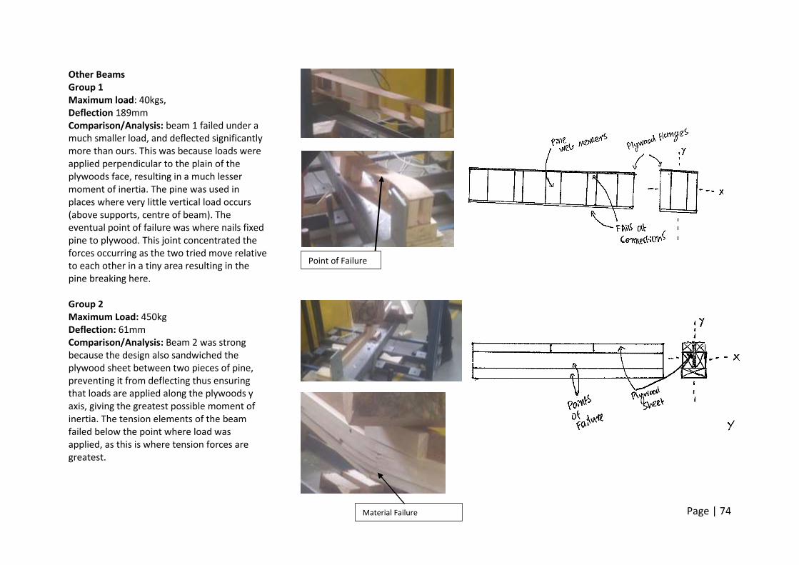
Page | 74
Other Beams Group 1 Maximum load: 40kgs, Deflection 189mm Comparison/Analysis: beam 1 failed under a much smaller load, and deflected significantly more than ours. This was because loads were applied perpendicular to the plain of the plywoods face, resulting in a much lesser moment of inertia. The pine was used in places where very little vertical load occurs (above supports, centre of beam). The eventual point of failure was where nails fixed pine to plywood. This joint concentrated the forces occurring as the two tried move relative to each other in a tiny area resulting in the pine breaking here. Group 2 Maximum Load: 450kg Deflection: 61mm Comparison/Analysis: Beam 2 was strong because the design also sandwiched the plywood sheet between two pieces of pine, preventing it from deflecting thus ensuring that loads are applied along the plywoods y axis, giving the greatest possible moment of inertia. The tension elements of the beam failed below the point where load was applied, as this is where tension forces are greatest.
Point of Failure
Material Failure
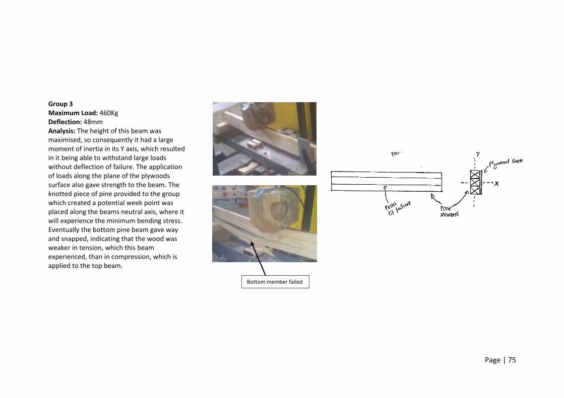
Page | 75
Group 3 Maximum Load: 460Kg Deflection: 48mm Analysis: The height of this beam was maximised, so consequently it had a large moment of inertia in its Y axis, which resulted in it being able to withstand large loads without deflection of failure. The application of loads along the plane of the plywoods surface also gave strength to the beam. The knotted piece of pine provided to the group which created a potential week point was placed along the beams neutral axis, where it will experience the minimum bending stress. Eventually the bottom pine beam gave way and snapped, indicating that the wood was weaker in tension, which this beam experienced, than in compression, which is applied to the top beam.
Bottom member failed
Page | 76
Glossary Tension forces Occur when part of a structure is pulled and particles in it move apart. The amount a material stretches depends on the magnitude of the load, its cross sectional area and the individual properties of that material Compression forces Occur when a force part of a structure and particles move closer together. This shortens the material. Columns Relatively thin, rigid vertical structural members designed to support axial compression loads applied to their ends Beams Rigid horizontal structural members Designed to transfer vertically applied loads laterally across space to supporting members. Subject to bending which must be resisted by materials internal strength.
Load Path The Path through which a load on a building is transferred to the ground. Loads always take the most direct route possible. Reaction Force The force applied by the ground on structural members that push down on it, in accordance with newtons third law. For a structure to be stable this must be equal and opposite too the applied load, holding it still. Point Load A load that acts on a structural member at a specific point rather than being distributed across it. Structural Joint The means by which two discrete structural members are fixed to each other and how loads or forces are transferred from one to the other. Frame A type of structure composed of long, ridged elements, some in compression and some in tension, very efficient at transferring loads to the ground.
Stability The likelihood of a structure to collapse. Its ability to resist external forces applied to it and those of its own self load. Bracing The use of diagonal member(s) to strengthen a square frame structure against lateral loads Masonry Discrete building blocks (eg stone, bricks, concrete blocks) held together with mortar. Masonry walls are strong in compression but weak in tension Moment A Moment is a force that causes a body to rotate about a point. Its magnitude is calculated by multiplying the strength of the force with the distance between its line of action and the point of rotation Retaining Wall A wall where the height on ground on one side is higher than the other. It must be strong enough to resist the lateral forces applied by the weight of the earth.
Page | 77
Pad Footing A pad or isolated footing is an individual spread footings that transfers localised loads to the ground over a wide area. Strip Footing An elongated spread footing that transfers the load of a wall or row of repeating elements Slab on Ground A flat slab known as a “raft footing” that transfers loads to ground by spreading them over a wide area. Substructure The part of a buildings structure that sits below the ground. Includes Foundations and the basement Joist The smaller, repeating beams that transfer loads on floorboards laterally to the main bearers or girders Girder The Primary beams in a steel frame flooring system that support the smaller joists.
Steel Decking A flooring system made up of steel elements including joist (secondary beams) and girders (primary beams) Span Is the distance along a structural member (horizontal or vertical) between supporting members. Measured edge to edge Spacing Distance (measured centre to centre) between repeating elements such as floors or columns. Determined by the spanning capability of the elements supporting it. Concrete Plank A flooring system made of pre- cast one way concrete beams spanning gap. Pitch The angle of a roof above horizontal. Stud The vertical members of a wooden stud frame wall. Individually they behave like narrow columns.
Nogging Short lateral braces between timber studs Lintel A Beam that vertical transfers loads laterally around a window opening. Axial Load An applied load that’s line of action is along the axis of a straight structural member. May be tensile of compressive Buckling The lateral deflection of a slender column under compressive load. Seasoned Timber Timber that has been dried until it has a moisture levels of below 15% of its original content. It is stronger than unseasoned timber Rafter A sloping structural beam that extends from the ridge or hip of a roof to the end of its eves
Page | 78
Purlin A horizontal structural beams that span the gaps between rafters, and in turn support the roof cladding. Cantilever A projecting structural member supported at only one end. Creates a moment which must be counterbalanced by the structure. Portal Frame A type of structural system made up of repeating structural frames. These must be able to resist lateral loads Eve The overhanging lower edge of a roof. Protects walls from weather Alloy A combination of two or more metals that results in physical properties differing from its constituent metals Soffit The underside of an overhanging eve. Top Chord The top beam(s) of a truss. Generally in compression.
Drip A break in the surface of a material that is wide enough to prevent the movement of water along it via capillary action, instead causing it to ‘drip’ off. Vapour barrier A membrane, usually plastic, such as sizilation that prevents the transmission of water vapour from one side to the other. Parapet Part of the buildings wall that extends above the height of its roof. Gutter Recessed channels that collect the water which drains off sloping rooves. Down Pipe Vertical pipes that discharge water caught in gutters into storm water systems or water tanks.
Flashing A thin continuous piece of impervious material (usually metal or plastic) that is installed at a joint or angle to prevent water penetration. Usually slopes towards a building’s exterior Insulation A layer of material installed in the enclosure system of a building that limits the transfer of either heat, sound, or fire through its skin. Sealant A substance that is inserted into a joint to prevent the passage of water and air, for example caulking. Sealants should durable, resilient and flexible. Sandwich Panel A composite material made up of a layer of insulation “sandwiched” between exterior panels, usually steel or aluminium. Composite Beam A beam made up of two different materials. Usually solid wooden flanges with plywood, Chipboard, of steel web flanges.
Page | 79
Bending The Deformation of a structural member from its true course. Deflection The perpendicular distance a spanning member deviates from its true course under a load. Shadow Line Joint A break between two surfaces to create a sharp aesthetic edge line. Cornice A horizontal Moulded projection that crowns a wall. It covers that joint between roof and ceiling. Skirting Also known as a baseboard. Attached to a wall at its base. Conceals the joint where the two meet and protects against damage Window Sash The framework into which window panes are set. Can be fixed or movable.
Door Furniture Also known as door hardware. Includes all the elements attached to a door to improve its functional or aesthetic qualities. This includes handles, hinges, locks, weather strips ect. Moment of Inertia An objects resistance to rotation. A measure of how difficult it is to rotate an object about a given axis. Dependent on this distance of an objects centre of mass from the point of rotation Stress The internal resistance of a material to deformation under applied loads Shear Force Forces acting on different parts of a body in opposite directions, for example the uniformly distributed downwards weight force of a beam and the upwards point forces of supports on it. Creates the tendency for the body to shear. Shear wall A solid wall capable of resisting changes in shape and transferring lateral loads to the ground.
Soft Storey A floor that has significantly less lateral stiffness than those above. Braced Frame A frame reinforced against lateral loads with diagonal members. Lifecycle The way a material behaves over the life of a building and afterwards, not just at the time of construction Fascia A horizontal band sitting directly underneath the edge of the roof. It encloses rafters. IEQ Indoor environmental Quality Corrosion The Chemical oxidation of metals.