Embed Size (px)
Citation preview
Distributed by
Any reference to Raytheon or RTN in this manual should be
interpreted as Raymarine. The names Raytheon and RTN
are owned by the Raytheon Company.

ST40 WindInstrumentOwner’sHandbook
Document number: 81160_3Date: 1st May 2001
160_3cov.p65 01/05/01, 16:141

Copyright © Raymarine Limited 2001
160_3cov.p65 01/05/01, 16:142
Preface i
Important information
WARNINGAlthough your ST40 instrument is designed to give accurate andreliable performance, it should serve only as an aid to navigationand should never lead to the erosion of good seamanship. Alwaysmaintain a permanent watch and be aware of situations as theydevelop.
EMC conformanceAll Raymarine equipment and accessories are designed to the bestindustry standards for use in the leisure marine environment.
The design and manufacture of Raymarine equipment and accessoriesconform to the appropriate Electromagnetic Compatibility (EMC)standards, but correct installation is required to ensure that performanceis not compromised.
Handbook informationTo the best of our knowledge, the information in this handbook wascorrect when it went to press. However, the Raymarine policy ofcontinuous product improvement may change product specificationswithout notice. Consequently, unavoidable differences may occurbetween the product and the handbook from time to time, for whichRaymarine cannot accept liability.
160_3pre.p65 01/05/01, 16:141

ii ST40 Wind Instrument Owner’s Handbook
160_3pre.p65 01/05/01, 16:142
Preface iii
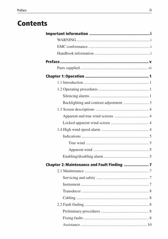
ContentsImportant information .......................................................... i
WARNING......................................................................... i
EMC conformance ............................................................. i
Handbook information ....................................................... i
Preface..................................................................................... v
Parts supplied ................................................................... vi
Chapter 1: Operation ............................................................. 1
1.1 Introduction ................................................................. 1
1.2 Operating procedures .................................................. 1
Silencing alarms .......................................................... 1
Backlighting and contrast adjustment ......................... 3
1.3 Screen descriptions ..................................................... 4
Apparent and true wind screens .................................. 4
Locked apparent wind screen ...................................... 4
1.4 High wind speed alarm ............................................... 4
Indications ................................................................... 5
True wind ............................................................... 5
Apparent wind ....................................................... 5
Enabling/disabling alarm ............................................. 5
Chapter 2: Maintenance and Fault Finding ........................ 7
2.1 Maintenance ................................................................ 7
Servicing and safety .................................................... 7
Instrument .................................................................... 7
Transducer ................................................................... 8
Cabling ........................................................................ 8
2.2 Fault finding ................................................................ 8
Preliminary procedures ............................................... 8
Fixing faults ................................................................. 8
Assistance .................................................................. 10
160_3pre.p65 01/05/01, 16:143
iv ST40 Wind Instrument Owner’s Handbook
Chapter 3: Installation ......................................................... 11
3.1 Planning your installation ......................................... 11
EMC installation guidelines ...................................... 11
Suppression Ferrites ........................................... 12
Connections to Other Equipment ......................... 12
Tools required ........................................................... 12
Site requirements ....................................................... 13
Rotavecta wind transducer ................................... 13
Instrument ............................................................ 13
3.2 Procedures ................................................................. 14
Fitting Rotavecta transducer ...................................... 14
Running transducer cable .................................... 15
Connections to the instrument ................................... 16
Stand-alone connections ...................................... 17
SeaTalk connections ............................................ 18
Fitting the instrument ................................................. 18
Desktop Mounting Bracket .................................. 20
3.3 Calibration requirement ............................................ 21
Chapter 4: Calibration ......................................................... 23
4.1 Introduction ............................................................... 23
EMC conformance .................................................... 23
4.2 User calibration ......................................................... 23
4.4 Dealer calibration ...................................................... 25
Instrument Specification .................................................... 27
Glossary ................................................................................. 29
Index ...................................................................................... 31
160_3pre.p65 01/05/01, 16:144
Preface v
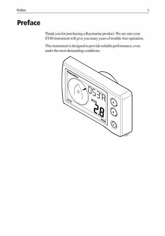
PrefaceThank you for purchasing a Raymarine product. We are sure yourST40 instrument will give you many years of trouble-free operation.
This instrument is designed to provide reliable performance, evenunder the most demanding conditions.
D4808-2
160_3pre.p65 01/05/01, 16:145
vi ST40 Wind Instrument Owner’s Handbook
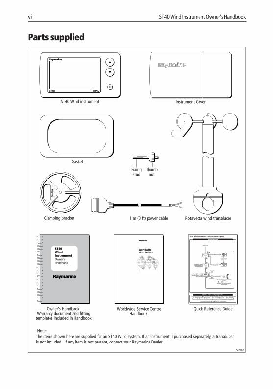
Parts supplied
Rotavecta wind transducer
D4752-3
ST40 WindInstrumentOwner'sHandbook
WorldwideDistributors
ST40 Wind instrument
Fixingstud
Thumbnut
Gasket
1 m (3 ft) power cable
Instrument Cover
Owner’s Handbook.Warranty document and fitting
templates included in Handbook
Worldwide Service CentreHandbook.
Quick Reference Guide
Clamping bracket
WINDST40
Note:The items shown here are supplied for an ST40 Wind system. If an instrument is purchased separately, a transduceris not included. If any item is not present, contact your Raymarine Dealer.
Adjusting display backlighting/contrast
Normal operation
ST40 Wind Instrument - quick reference guide
orTo exit adjust mode press or wait for 5 second timeout
LEVEL 1 LEVEL 1OFF LEVEL 2LEVEL 3LEVEL 2
To enter adjust mode, press for 1 second to adjust BACKLIGHTING and a further 1 second to adjust CONTRAST
SWITCH ON
Apparentwind
Truewind
3 seconds
Setalarmlevel
Alarm on/off
Only available on masterinstruments. Times out to the
previous permanent screenafter 5 seconds.
Highwind speed
alarm
Lockedapparent
wind
Auto lockedapparent
windAvailable only if boatspeed information is
present on SeaTalk
Course computersets vane lock
Course computersets vane lock
+
-MomentaryWith Set alarm level screen displayed,
to save the alarm level and return tonormal operation.
and keys simultaneouslypress the
160_3pre.p65 01/05/01, 16:146
Chapter 1: Operation 1
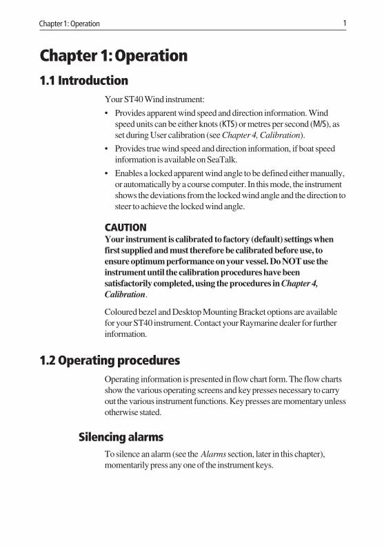
Chapter 1: Operation1.1 Introduction
Your ST40 Wind instrument:
• Provides apparent wind speed and direction information. Windspeed units can be either knots (KTS) or metres per second (M/S), asset during User calibration (see Chapter 4, Calibration).
• Provides true wind speed and direction information, if boat speedinformation is available on SeaTalk.
• Enables a locked apparent wind angle to be defined either manually,or automatically by a course computer. In this mode, the instrumentshows the deviations from the locked wind angle and the direction tosteer to achieve the locked wind angle.
CAUTIONYour instrument is calibrated to factory (default) settings whenfirst supplied and must therefore be calibrated before use, toensure optimum performance on your vessel. Do NOT use theinstrument until the calibration procedures have beensatisfactorily completed, using the procedures in Chapter 4,Calibration.
Coloured bezel and Desktop Mounting Bracket options are availablefor your ST40 instrument. Contact your Raymarine dealer for furtherinformation.
1.2 Operating proceduresOperating information is presented in flow chart form. The flow chartsshow the various operating screens and key presses necessary to carryout the various instrument functions. Key presses are momentary unlessotherwise stated.
Silencing alarmsTo silence an alarm (see the Alarms section, later in this chapter),momentarily press any one of the instrument keys.
160_3c01.p65 01/05/01, 16:141
2 ST40 Wind Instrument Owner’s Handbook
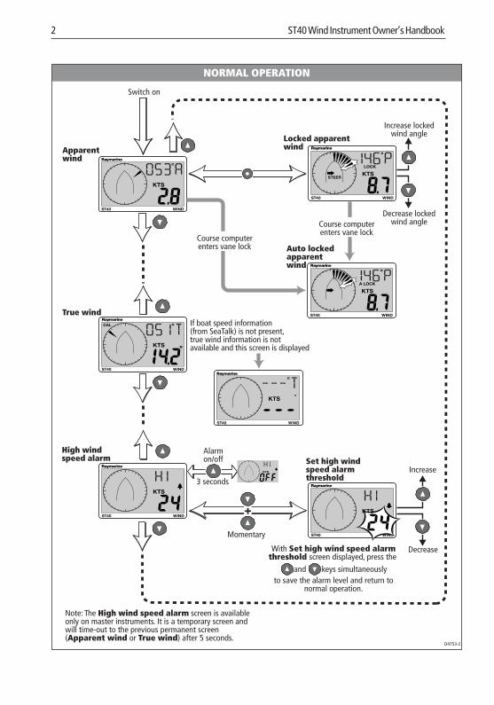
NORMAL OPERATION
Apparentwind
D4753-2
Note: The High wind speed alarm screen is availableonly on master instruments. It is a temporary screen andwill time-out to the previous permanent screen(Apparent wind or True wind) after 5 seconds.
Switch on
WIND
CAL
True wind
High windspeed alarm
STEER
Locked apparentwind
Auto lockedapparentwind
Increase lockedwind angle
Decrease lockedwind angle
Course computerenters vane lock
WINDST40
Increase
Decrease
3 seconds
Alarmon/off Set high wind
speed alarmthreshold
ST40
WINDST40
WINDST40
WINDST40
WINDST40
Course computerenters vane lock
+
With Set high wind speed alarmthreshold screen displayed, press the
to save the alarm level and return tonormal operation.
and keys simultaneously
Momentary
If boat speed information(from SeaTalk) is not present,true wind information is notavailable and this screen is displayed
160_3c01.p65 01/05/01, 16:152
Chapter 1: Operation 3
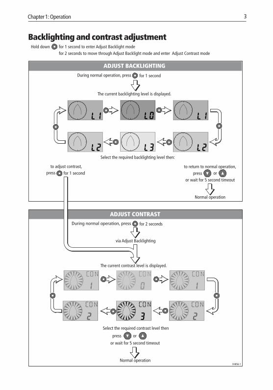
Backlighting and contrast adjustment
During normal operation, press
During normal operation, press
The current backlighting level is displayed.
for 1 second
Select the required backlighting level then:
Normal operation
ADJUST BACKLIGHTING
or wait for 5 second timeout
orpress
D4856-1
The current contrast level is displayed.
Select the required contrast level then
orpress
Normal operation
ADJUST CONTRAST
or wait for 5 second timeout
Hold down for 1 second to enter Adjust Backlight modefor 2 seconds to move through Adjust Backlight mode and enter Adjust Contrast mode
via Adjust Backlighting
for 2 seconds
press for 1 second to adjust contrast, to return to normal operation,
160_3c01.p65 01/05/01, 16:153
4 ST40 Wind Instrument Owner’s Handbook
1.3 Screen descriptions
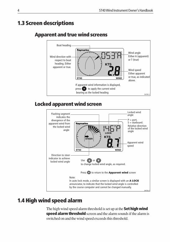
Apparent and true wind screens
If apparent wind information is displayed,
bearing as the locked headingD4792-2
Wind direction withrespect to boatheading. Either
apparent or true.
Wind angleEither A (apparent)or T (true)
Wind speedEither apparentor true, as indicatedabove.
Boat heading
to apply the current windpress
Locked apparent wind screen
D4793-2
Note:In auto lock mode, a similar screen is displayed with an A LOCKannunciator, to indicate that the locked wind angle is controlledby the course computer and cannot be changed manually.
STEER
Relative directionof the locked windangle
Flashing segmentindicates the
divergence of theapparent wind from
the locked windangle
Locked windangle
Apparent windspeed
P = port,S = starboard.
Direction to steerindicator to achieve
locked wind angle Use orto change locked wind angle, as required.
Press to return to the Apparent wind screen
1.4 High wind speed alarmThe high wind speed alarm threshold is set up at the Set high windspeed alarm threshold screen and the alarm sounds if the alarm isswitched on and the wind speed exceeds this threshold.
160_3c01.p65 01/05/01, 16:154
Chapter 1: Operation 5
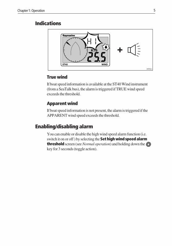
Indications
D4754-2
WINDST40
True windIf boat speed information is available at the ST40 Wind instrument(from a SeaTalk bus), the alarm is triggered if TRUE wind speedexceeds the threshold.
Apparent windIf boat speed information is not present, the alarm is triggered if theAPPARENT wind speed exceeds the threshold.
Enabling/disabling alarmYou can enable or disable the high wind speed alarm function (i.e.switch it on or off ) by selecting the Set high wind speed alarmthreshold screen (see Normal operation) and holding down the key for 3 seconds (toggle action).
160_3c01.p65 01/05/01, 16:155

6 ST40 Wind Instrument Owner’s Handbook
160_3c01.p65 01/05/01, 16:156
Chapter 2: Maintenance and Fault Finding 7
Chapter 2: Maintenance and Fault Finding2.1 Maintenance
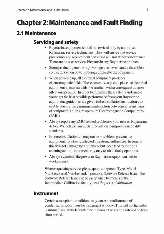
Servicing and safety• Raymarine equipment should be serviced only by authorised
Raymarine service technicians. They will ensure that serviceprocedures and replacement parts used will not affect performance.There are no user-serviceable parts in any Raymarine product.
• Some products generate high voltages, so never handle the cables/connectors when power is being supplied to the equipment.
• When powered up, all electrical equipment produceselectromagnetic fields. These can cause adjacent pieces of electricalequipment to interact with one another, with a consequent adverseaffect on operation. In order to minimise these effects and enableyou to get the best possible performance from your Raymarineequipment, guidelines are given in the installation instructions, toenable you to ensure minimum interaction between different itemsof equipment, i.e. ensure optimum Electromagnetic Compatibility(EMC).
• Always report any EMC-related problem to your nearest Raymarinedealer. We will use any such information to improve our qualitystandards.
• In some installations, it may not be possible to prevent theequipment from being affected by external influences. In generalthis will not damage the equipment but it can lead to spuriousresetting action, or momentarily may result in faulty operation.
• Always switch off the power to Raymarine equipment beforeworking on it.
When requesting service, please quote equipment Type, ModelNumber, Serial Number and, if possible, Software Release Issue. TheSoftware Release Issue can be ascertained by means of theIntermediate Calibration facility, see Chapter 4, Calibration.
InstrumentCertain atmospheric conditions may cause a small amount ofcondensation to form on the instrument window. This will not harm theinstrument and will clear after the instrument has been switched on for ashort period.
160_3c02.p65 01/05/01, 16:157
8 ST40 Wind Instrument Owner’s Handbook
Periodically clean your ST40 instrument with a soft damp cloth. DoNOT use chemical or abrasive materials to clean the instrument.
CablingExamine all cables for chafing or other damage to the outer shield and,where necessary, replace and re-secure.
2.2 Fault finding
Preliminary proceduresIf you appear to have a problem, first check the security of theconnections at the rear of the instrument and reconnect any that areloose.
Changes in the electronic environment may adversely affect theoperation of your ST40 equipment. Typical examples of such changesare:
• Electrical equipment has recently been installed or moved aboardyour vessel.
• You are in the vicinity of another vessel or shore station emittingradio signals.
Fixing faultsAll Raymarine products are subjected to comprehensive test andquality assurance programmes prior to packing and shipping. However,if a fault occurs, the following guidelines may help to identify andrectify the problem.
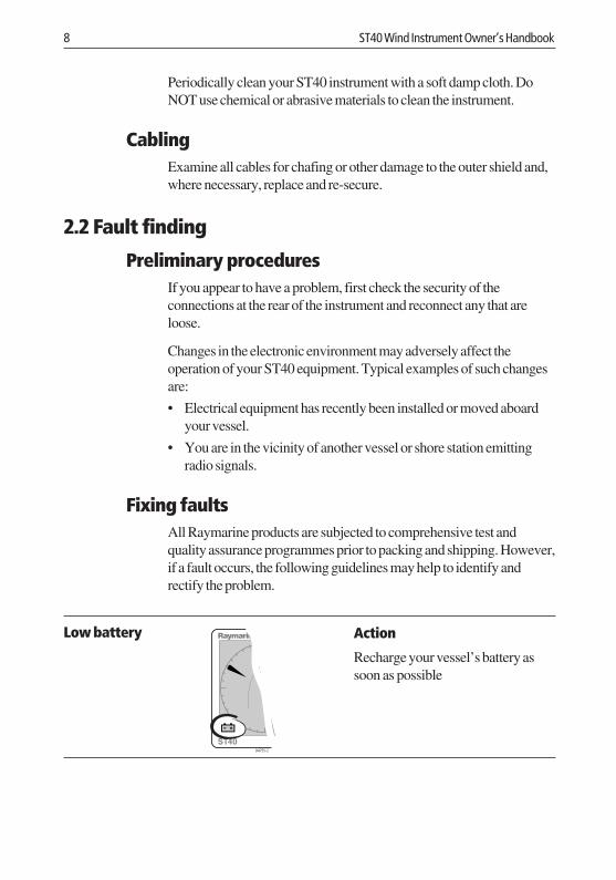
Action
Recharge your vessel’s battery assoon as possible
D4755-2
Low battery
160_3c02.p65 01/05/01, 16:158
Chapter 2: Maintenance and Fault Finding 9
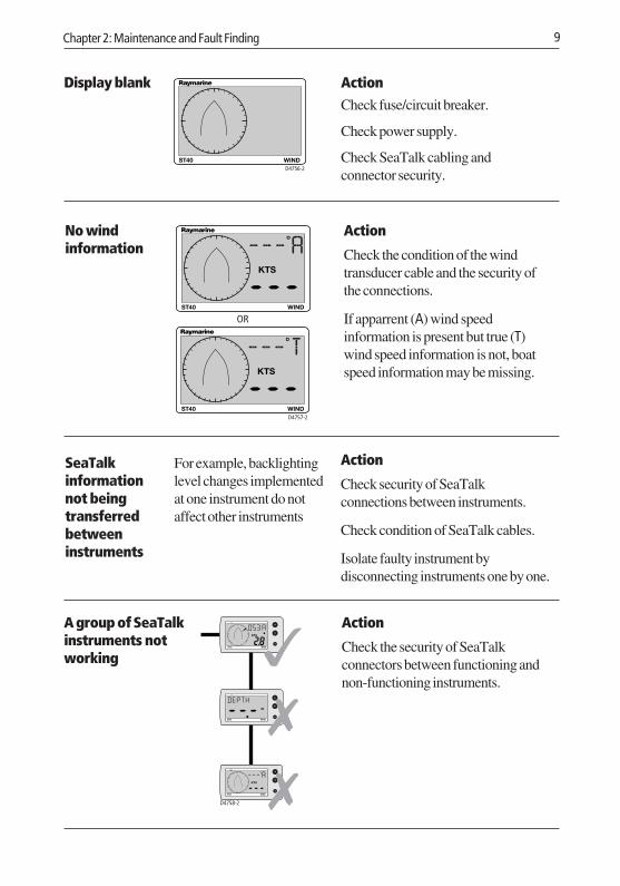
ActionCheck fuse/circuit breaker.
Check power supply.
Check SeaTalk cabling andconnector security.
D4756-2WINDST40
Action
Check the condition of the windtransducer cable and the security ofthe connections.
If apparrent (A) wind speedinformation is present but true (T)wind speed information is not, boatspeed information may be missing.
No windinformation
Display blank
D4757-2
ORWINDST40
WINDST40
A group of SeaTalkinstruments notworking
Action
Check the security of SeaTalkconnectors between functioning andnon-functioning instruments.
D4758-2
WINDST40
WINDST40
WINDST40
Action
Check security of SeaTalkconnections between instruments.
Check condition of SeaTalk cables.
Isolate faulty instrument bydisconnecting instruments one by one.
SeaTalkinformationnot beingtransferredbetweeninstruments
For example, backlightinglevel changes implementedat one instrument do notaffect other instruments
160_3c02.p65 01/05/01, 16:159

10 ST40 Wind Instrument Owner’s Handbook
AssistanceIf you are unable to rectify any problem, please contact your localRaymarine Dealer for assistance.
160_3c02.p65 01/05/01, 16:1510
Chapter 3: Installation 11
Chapter 3: InstallationThis chapter describes how to install the ST40 Wind instrument, andassociated Rotavecta wind transducer.
3.1 Planning your installationDetermine the best positions for both transducer and instrument, suchthat the EMC installation guidelines and the Site Requirements (below)are satisfied.
EMC installation guidelinesAll Raymarine equipment and accessories are designed to the bestindustry standards for use in the leisure marine environment.
Their design and manufacture conform to the appropriateElectromagnetic Compatibility (EMC) standards, but correctinstallation is required to ensure that performance is not compromised.Although every effort has been taken to ensure that they will performunder all conditions, it is important to understand what factors couldaffect the operation of the product.
The guidelines given here describe the conditions for optimum EMCperformance, but it is recognised that it may not be possible to meet allof these conditions in all situations. To ensure the best possibleconditions for EMC performance within the constraints imposed byany location, always ensure the maximum separation possible betweendifferent items of electrical equipment.
For optimum EMC performance, it is recommended that whereverpossible:
• All Raymarine equipment and cables connected to it are:
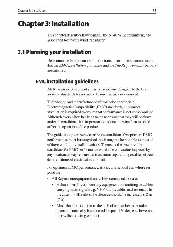
• At least 1 m (3 feet) from any equipment transmitting or cablescarrying radio signals e.g. VHF radios, cables and antennas. Inthe case of SSB radios, the distance should be increased to 2 m(7 ft).
• More than 2 m (7 ft) from the path of a radar beam. A radarbeam can normally be assumed to spread 20 degrees above andbelow the radiating element.
160_3c03 .p65 01/05/01, 16:1511
12 ST40 Wind Instrument Owner’s Handbook
• The equipment is supplied from a different battery from that used forengine start. Voltage drops below 10 V in the power supply to ourproducts, and starter motor transients, can cause the equipment toreset. This will not damage the equipment, but may cause the loss ofsome information and may change the operating mode.
• Raymarine specified cables are used at all times. Cutting andrejoining these cables can compromise EMC performance and somust be avoided unless doing so is detailed in the installationmanual.
• If a suppression ferrite is attached to a cable, this ferrite should notbe removed. If the ferrite needs to be removed during installation itmust be reassembled in the same position.
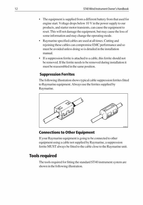
Suppression FerritesThe following illustration shows typical cable suppression ferrites fittedto Raymarine equipment. Always use the ferrites supplied byRaymarine.
D3548-2
Connections to Other EquipmentIf your Raymarine equipment is going to be connected to otherequipment using a cable not supplied by Raymarine, a suppressionferrite MUST always be fitted to the cable close to the Raymarine unit.
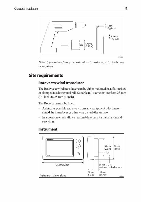
Tools requiredThe tools required for fitting the standard ST40 instrument system areshown in the following illustration.
160_3c03 .p65 01/05/01, 16:1512
Chapter 3: Installation 13
57 mm(2.25 in)
D4643-3
4 mm(5/32 inch)
2.5 mm(1/10 inch)
Note: If you intend fitting a nonstandard transducer, extra tools maybe required
Site requirements
Rotavecta wind transducerThe Rotavecta wind transducer can be either mounted on a flat surfaceor clamped to a horizontal rail. Suitable rail diameters are from 23 mm(29/32 inch) to 25 mm (1 inch).
The Rotavecta must be fitted:
• As high as possible and away from any equipment which mayshield the transducer or otherwise disturb the air flow.
• In a position which allows reasonable access for installation andservicing.
Instrument
D4644-2Instrument dimensions
126 mm (5.0 in)
21 mm(0.8 in)
17 mm(0.67 in)
55 mm(2.2 in)
70 mm(2.8 in)
30 mm (1.2 in)minimum cable clearance
ST40
160_3c03 .p65 01/05/01, 16:1513
14 ST40 Wind Instrument Owner’s Handbook
CAUTION:The presence of moisture at the rear of the instrument could causedamage either by entering the instrument through the breathinghole or by coming into contact with the electrical connectors.
Each instrument must be positioned where:
• It is easily read by the helmsman or navigator
• It is protected against physical damage
• It is at least 230 mm (9 in) from a compass
• It is at least 500 mm (20 in) from radio receiving equipment
• There is reasonable rear access for installation and servicing
• The rear of the instrument is protected from water.
3.2 ProceduresAdapt these procedures as appropriate, to suit your individualrequirement.
CAUTION:Where it is necessary to cut holes (e.g. for cable routing andinstrument mounting), ensure that these will not cause a hazard byweakening critical parts of the vessel’s structure. If in doubt, seekadvice from a reputable boat builder.
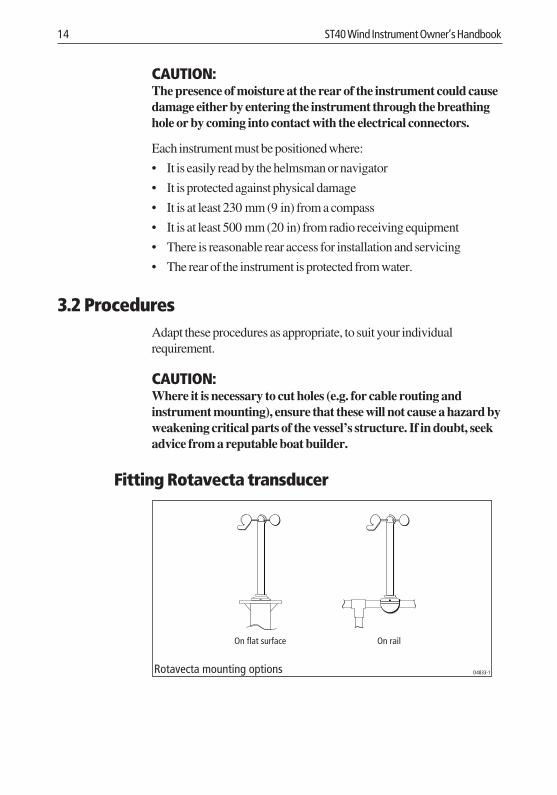
Fitting Rotavecta transducer
On rail
Rotavecta mounting options
On flat surface
D4833-1
160_3c03 .p65 01/05/01, 16:1514
Chapter 3: Installation 15
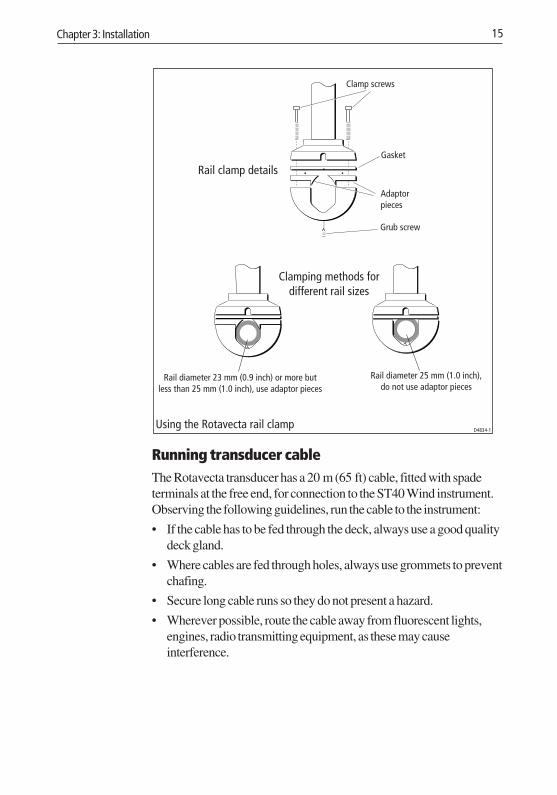
Clamp screws
Gasket
Adaptorpieces
Grub screw
Rail diameter 23 mm (0.9 inch) or more butless than 25 mm (1.0 inch), use adaptor pieces
Rail diameter 25 mm (1.0 inch),do not use adaptor pieces
Clamping methods fordifferent rail sizes
D4834-1
Rail clamp details
Using the Rotavecta rail clamp
Running transducer cableThe Rotavecta transducer has a 20 m (65 ft) cable, fitted with spadeterminals at the free end, for connection to the ST40 Wind instrument.Observing the following guidelines, run the cable to the instrument:
• If the cable has to be fed through the deck, always use a good qualitydeck gland.
• Where cables are fed through holes, always use grommets to preventchafing.
• Secure long cable runs so they do not present a hazard.
• Wherever possible, route the cable away from fluorescent lights,engines, radio transmitting equipment, as these may causeinterference.
160_3c03 .p65 01/05/01, 16:1515
16 ST40 Wind Instrument Owner’s Handbook
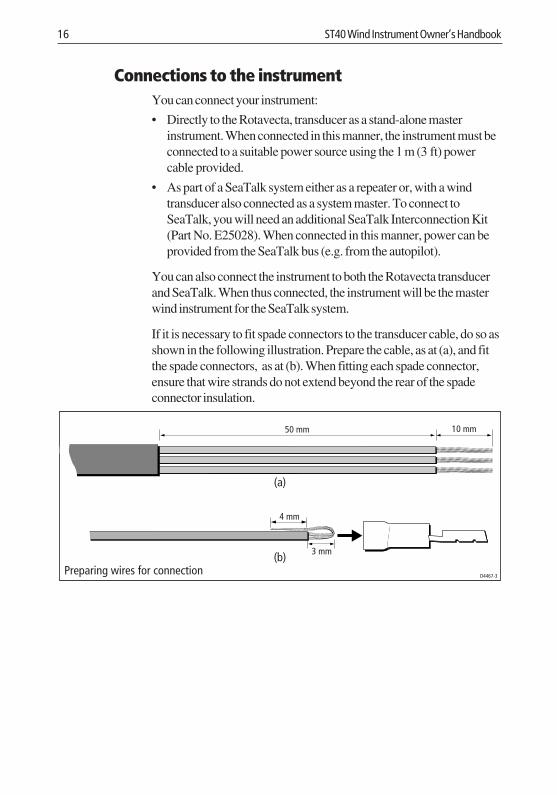
Connections to the instrumentYou can connect your instrument:
• Directly to the Rotavecta, transducer as a stand-alone masterinstrument. When connected in this manner, the instrument must beconnected to a suitable power source using the 1 m (3 ft) powercable provided.
• As part of a SeaTalk system either as a repeater or, with a windtransducer also connected as a system master. To connect toSeaTalk, you will need an additional SeaTalk Interconnection Kit(Part No. E25028). When connected in this manner, power can beprovided from the SeaTalk bus (e.g. from the autopilot).
You can also connect the instrument to both the Rotavecta transducerand SeaTalk. When thus connected, the instrument will be the masterwind instrument for the SeaTalk system.
If it is necessary to fit spade connectors to the transducer cable, do so asshown in the following illustration. Prepare the cable, as at (a), and fitthe spade connectors, as at (b). When fitting each spade connector,ensure that wire strands do not extend beyond the rear of the spadeconnector insulation.
D4467-3
3 mm
4 mm
10 mm50 mm
Preparing wires for connection
(a)
(b)
160_3c03 .p65 01/05/01, 16:1516
Chapter 3: Installation 17
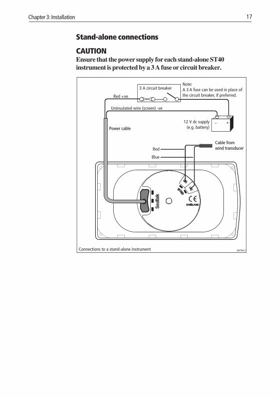
Stand-alone connections
CAUTIONEnsure that the power supply for each stand-alone ST40instrument is protected by a 3 A fuse or circuit breaker.
3 A circuit breaker
Red +ve
Uninsulated wire (screen) -ve
+_
D4794-2Connections to a stand-alone instrument
Cable from wind transducer
Power cable
Blue
Red
Note:A 3 A fuse can be used in place ofthe circuit breaker, if preferred.
12 V dc supply(e.g. battery)
160_3c03 .p65 01/05/01, 16:1517
18 ST40 Wind Instrument Owner’s Handbook
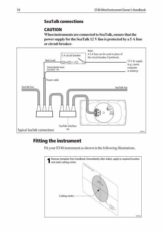
SeaTalk connections
CAUTIONWhen instruments are connected to SeaTalk, ensure that thepower supply for the SeaTalk 12 V line is protected by a 5 A fuseor circuit breaker.
5 A circuit breaker
Red (+ve) 12 V dc supply(e.g. coursecomputeror battery)
Uninsulated wire(screen) -ve
D4826-2Typical SeaTalk connections
SeaTalk bus SeaTalk bus
SeaTalk interfacekit
Power cable
Note:A 5 A fuse can be used in place ofthe circuit breaker, if preferred.
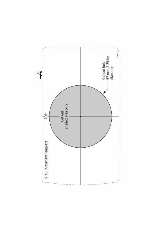
Fitting the instrumentFit your ST40 instrument as shown in the following illustrations.
1
D4759-1
Cutting centre
TOP
Cut outshaded area only
Cut out hole57 mm (2.25 in)
diameter
ST40 Instrument Template
Remove template from handbook (immediately after index), apply to required locationand mark cutting centre.
160_3c03 .p65 01/05/01, 16:1518
Chapter 3: Installation 19
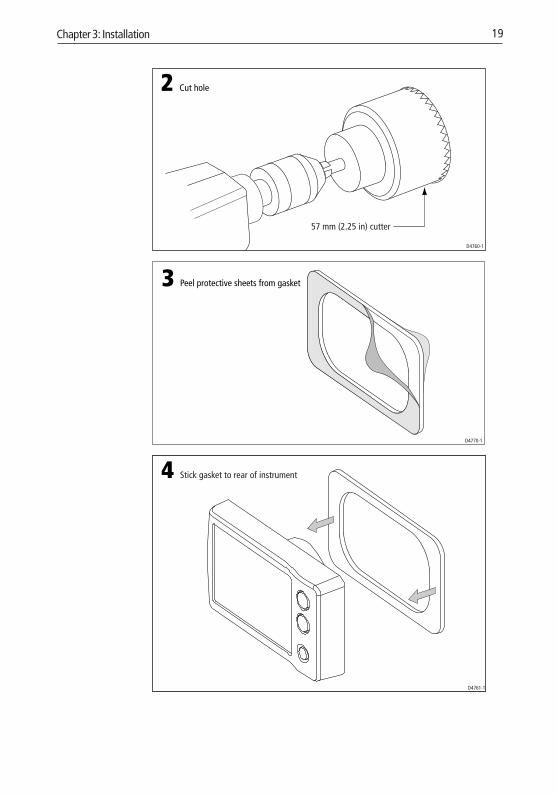
2 Cut hole
57 mm (2.25 in) cutter
D4760-1
Peel protective sheets from gasket3
D4770-1
4 Stick gasket to rear of instrument
D4761-1
160_3c03 .p65 01/05/01, 16:1619
20 ST40 Wind Instrument Owner’s Handbook
D4819-1
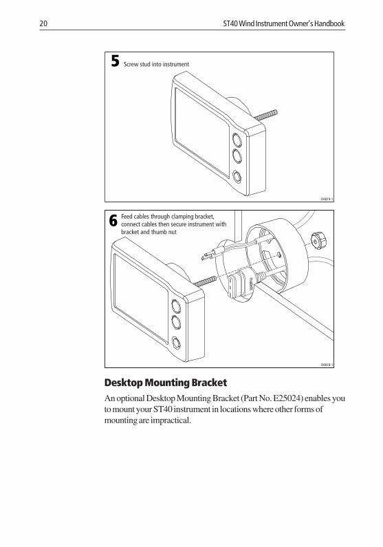
5 Screw stud into instrument
D4818-1
6 Feed cables through clamping bracket,connect cables then secure instrument withbracket and thumb nut
Desktop Mounting BracketAn optional Desktop Mounting Bracket (Part No. E25024) enables youto mount your ST40 instrument in locations where other forms ofmounting are impractical.
160_3c03 .p65 01/05/01, 16:1620
Chapter 3: Installation 21
D4646-1
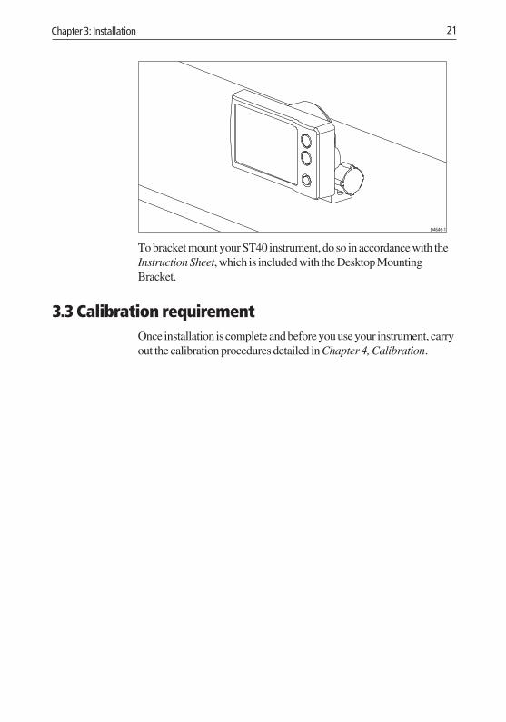
To bracket mount your ST40 instrument, do so in accordance with theInstruction Sheet, which is included with the Desktop MountingBracket.
3.3 Calibration requirementOnce installation is complete and before you use your instrument, carryout the calibration procedures detailed in Chapter 4, Calibration.
160_3c03 .p65 01/05/01, 16:1621

22 ST40 Wind Instrument Owner’s Handbook
160_3c03 .p65 01/05/01, 16:1622
Chapter 4: Calibration 23
Chapter 4: Calibration4.1 Introduction
The procedures in this Chapter must be carried out before theequipment is used operationally, to optimise the performance of theinstrument with the vessel.
Calibration information is presented in flow chart form. The flow chartsshow the various calibration screens and key presses necessary to carryout calibration. All key presses are momentary unless otherwise stated.
EMC conformance• Always check the installation before going to sea to make sure that it
is not affected by radio transmissions, engine starting etc.
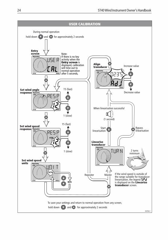
4.2 User calibrationUser calibration enables you to:
• Set the wind angle and speed response values. Use higher responsevalues for rapid updates in reasonable weather conditions (forexample, when you are trying to maintain a locked course). Uselower response values in squally conditions to damp out unstablereadings.
• Set the required wind speed units, either KTS (knots) or M/S (metresper second).
• Linearise and align the wind transducer.
Power up the instrument then follow the procedure in the Usercalibration flow diagram.
160_3c04.p65 01/05/01, 16:1623
24 ST40 Wind Instrument Owner’s Handbook
USER CALIBRATION
Entryscreen
Set wind angleresponse
for approximately 2 secondshold down and
15 (fast)
1 (slow)
D4764-2
15 (fast)
1 (slow)
Set wind speedresponse
WIND
WINDST40
CAL
WINDST40
CAL
CAL
Increase value
Decrease value
Aligntransducer
CAL
Linearisetransducer
ST40
WINDST40
WINDST40
During normal operation
for approximately 2 secondshold down and
To save your settings and return to normal operation from any screen,
MasterRepeater
Set wind speedunits
CAL
WINDST40M/S
When linearisation successful
(1 second)
Bypasslinearisation
Startlinearisation
If the wind speed is outside ofthe range suitable for transducerlinearisation, the legendis displayed on the Linearisetransducer screen.
2 turnsminimum
Note:If there is no keyactivity when theEntry screen isdisplayed, calibrationwill time out tonormal operationafter 5 seconds,
160_3c04.p65 01/05/01, 16:1624
Chapter 4: Calibration 25
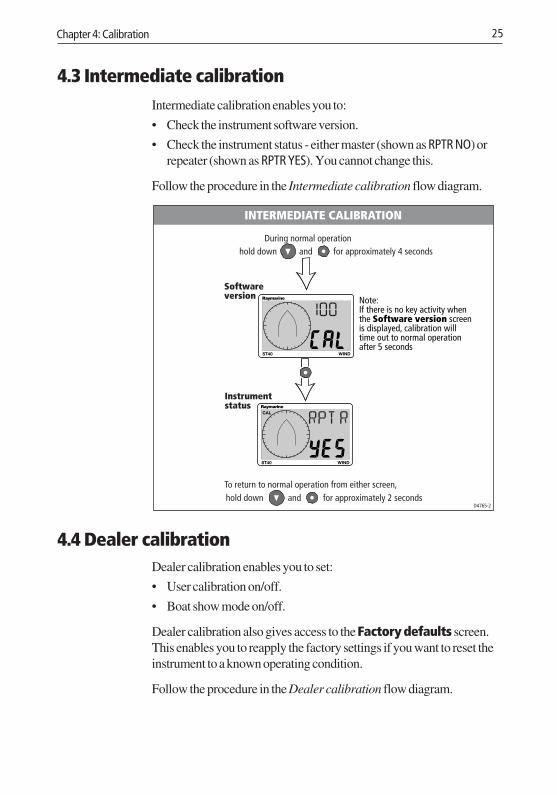
4.3 Intermediate calibrationIntermediate calibration enables you to:
• Check the instrument software version.
• Check the instrument status - either master (shown as RPTR NO) orrepeater (shown as RPTR YES). You cannot change this.
Follow the procedure in the Intermediate calibration flow diagram.
Softwareversion
D4765-2
for approximately 4 secondshold down and
Instrumentstatus
To return to normal operation from either screen,
WIND
CAL
During normal operation
ST40
WINDST40
for approximately 2 secondsandhold down
INTERMEDIATE CALIBRATION
Note:If there is no key activity whenthe Software version screenis displayed, calibration willtime out to normal operationafter 5 seconds
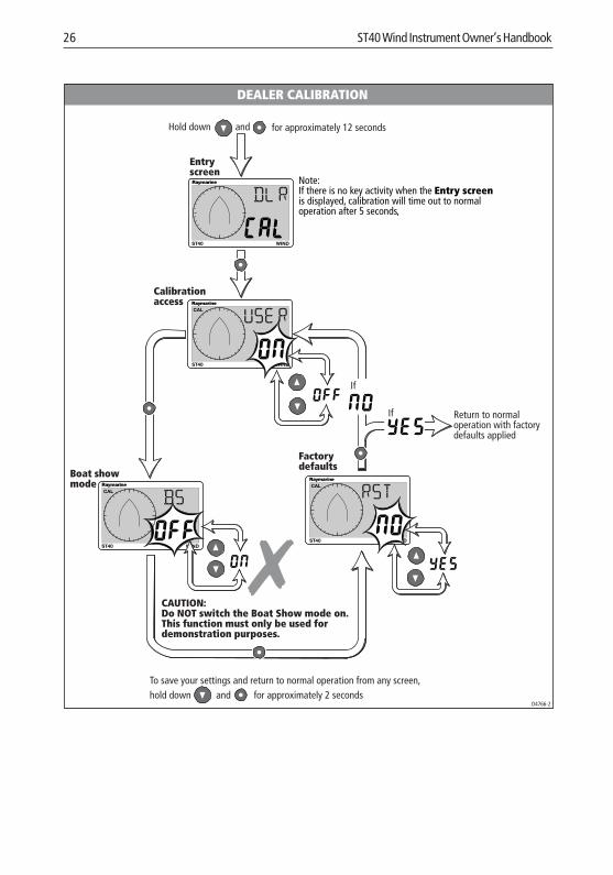
4.4 Dealer calibrationDealer calibration enables you to set:
• User calibration on/off.
• Boat show mode on/off.
Dealer calibration also gives access to the Factory defaults screen.This enables you to reapply the factory settings if you want to reset theinstrument to a known operating condition.
Follow the procedure in the Dealer calibration flow diagram.
160_3c04.p65 01/05/01, 16:1625
26 ST40 Wind Instrument Owner’s Handbook
CAUTION:Do NOT switch the Boat Show mode on.This function must only be used fordemonstration purposes.
To save your settings and return to normal operation from any screen,
DEALER CALIBRATION
Entryscreen
D4766-2
for approximately 12 secondsHold down and
Calibrationaccess
Boat showmode
Factorydefaults
for approximately 2 secondshold down and
WINDST40
CAL
Return to normaloperation with factorydefaults applied
If
If
WINDST40
CAL
WIND
CAL
ST40
WINDST40
Note:If there is no key activity when the Entry screenis displayed, calibration will time out to normaloperation after 5 seconds,
160_3c04.p65 01/05/01, 16:1626
Instrument Specification 27
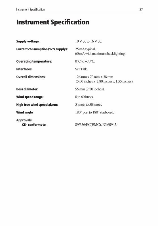
Instrument Specification
Supply voltage: 10 V dc to 16 V dc.
Current consumption (12 V supply): 25 mA typical.60 mA with maximum backlighting.
Operating temperature: 0°C to +70°C.
Interfaces: SeaTalk.
Overall dimensions: 126 mm x 70 mm x 38 mm (5.00 inches x 2.80 inches x 1.55 inches).
Boss diameter: 55 mm (2.20 inches).
Wind speed range: 0 to 60 knots.
High true wind speed alarm: 5 knots to 50 knots.
Wind angle 180° port to 180° starboard.
Approvals:CE - conforms to 89/336/EC(EMC), EN60945.
160_3spe.p65 01/05/01, 16:1627

28 ST40 Wind Instrument Owner’s Handbook
160_3spe.p65 01/05/01, 16:1628
Glossary 29
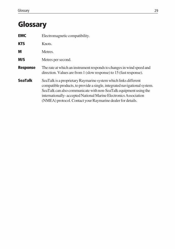
GlossaryEMC Electromagnetic compatibility.
KTS Knots.
M Metres.
M/S Metres per second.
Response The rate at which an instrument responds to changes in wind speed anddirection. Values are from 1 (slow response) to 15 (fast response).
SeaTalk SeaTalk is a proprietary Raymarine system which links differentcompatible products, to provide a single, integrated navigational system.SeaTalk can also communicate with non-SeaTalk equipment using theinternationally- accepted National Marine Electronics Association(NMEA) protocol. Contact your Raymarine dealer for details.
160_3glo.p65 01/05/01, 16:1629

30 ST40 Wind Instrument Owner’s Handbook
160_3glo.p65 01/05/01, 16:1630
Index 31
Index
A
Alarmenable/disable 5indications 5range 27setting level 2silencing 1
Align transducer 24Apparent wind speed 2Apparent/true wind screen 4
B
Backlighting 3Boat show mode 25
C
Calibration 23–26Dealer 25–26Intermediate 25setting user access 26User 23–24
Calibration requirement 1, 21Cleaning the instrument 8Condensation 7Connecting the instrument 16–18Contrast 3Current consumption 27
D
Dealer calibration 25–26Desktop Mounting Bracket 20–21Dimensions 27
E
EMCconformance i, 23installation guidelines 11–12
F
Factory defaults 25Fault finding 8
assistance 10blank display 9low battery 8no wind information 9SeaTalk problems 9
H
High wind speed alarm 4enable/disable 5indications 5setting level 2
I
Installation 11–21connecting the instrument 16–18fitting the instrument 18–21planning 11–14Rotavecta wind transducer 14–15site requirements 13–14tools required 12–13
Instrumentcleaning 8condensation 7connecting 16–18current consumption 27dimensions 27fitting 18–21site requirements 13–14status (master or repeater) 25supply voltage 27
Intermediate calibration 25
160_3ind.p65 01/05/01, 16:1631
32 ST40 Wind Instrument Owner’s Handbook
L
Linearising transducer 24Locked apparent wind screen 4Locked wind angle
auto lock 2manual setting 2
Low battery indication 8
M
Maintenance 7–8
N
Normal operation 2–3
O
Operating temperature 27Operation 1–5
P
Parts supplied vi
R
Rotavectafitting 14–15site requirements 13
S
Servicing and safety 7Setting
backlighting 3contrast 3high wind alarm level 2wind angle response 24wind speed response 24wind speed units 24
Silencing alarm 1Site requirements 13–14
instrument 13–14transducer 13
Software version 25Specifications 27
T
Transduceraligning 24fitting 14–15linearising 24site requirements 13
True wind speed 2
U
User calibration 23–24
V
Voltage 27
W
Wind angleappropriate response values 23range 27set response 24
Wind speedappropriate response values 23range 27set response 24set units 24
160_3ind.p65 01/05/01, 16:1632
D480
0-1
TOP
Cut o
utsh
aded
are
a on
ly
Cut o
ut h
ole
57 m
m (2
.25
in)
diam
eter
ST40
Inst
rum
ent T
empl
ate
160_3tem.p65 01/05/01, 16:1633

160_3tem.p65 01/05/01, 16:1634
Document number: 84064-8April 2001
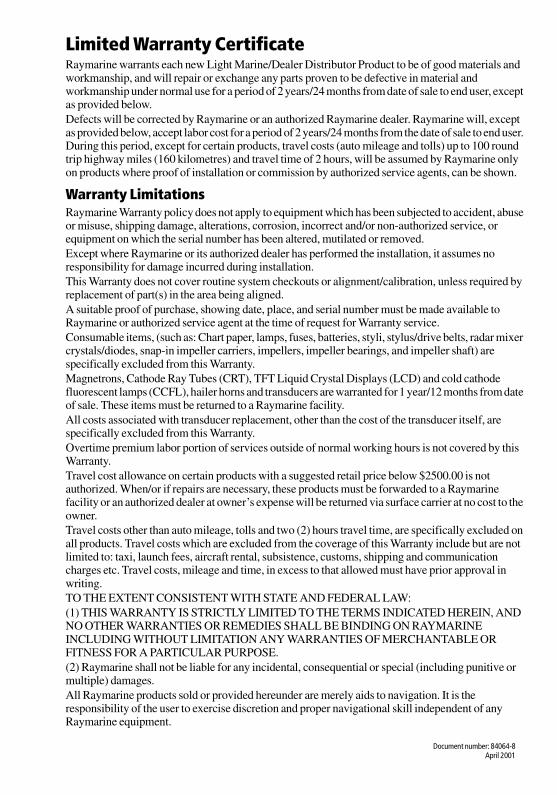
Limited Warranty CertificateRaymarine warrants each new Light Marine/Dealer Distributor Product to be of good materials and workmanship, and will repair or exchange any parts proven to be defective in material and workmanship under normal use for a period of 2 years/24 months from date of sale to end user, except as provided below.Defects will be corrected by Raymarine or an authorized Raymarine dealer. Raymarine will, except as provided below, accept labor cost for a period of 2 years/24 months from the date of sale to end user. During this period, except for certain products, travel costs (auto mileage and tolls) up to 100 round trip highway miles (160 kilometres) and travel time of 2 hours, will be assumed by Raymarine only on products where proof of installation or commission by authorized service agents, can be shown.
Warranty LimitationsRaymarine Warranty policy does not apply to equipment which has been subjected to accident, abuse or misuse, shipping damage, alterations, corrosion, incorrect and/or non-authorized service, or equipment on which the serial number has been altered, mutilated or removed.Except where Raymarine or its authorized dealer has performed the installation, it assumes no responsibility for damage incurred during installation.This Warranty does not cover routine system checkouts or alignment/calibration, unless required by replacement of part(s) in the area being aligned.A suitable proof of purchase, showing date, place, and serial number must be made available to Raymarine or authorized service agent at the time of request for Warranty service.Consumable items, (such as: Chart paper, lamps, fuses, batteries, styli, stylus/drive belts, radar mixer crystals/diodes, snap-in impeller carriers, impellers, impeller bearings, and impeller shaft) are specifically excluded from this Warranty.Magnetrons, Cathode Ray Tubes (CRT), TFT Liquid Crystal Displays (LCD) and cold cathode fluorescent lamps (CCFL), hailer horns and transducers are warranted for 1 year/12 months from date of sale. These items must be returned to a Raymarine facility.All costs associated with transducer replacement, other than the cost of the transducer itself, are specifically excluded from this Warranty.Overtime premium labor portion of services outside of normal working hours is not covered by this Warranty.Travel cost allowance on certain products with a suggested retail price below $2500.00 is not authorized. When/or if repairs are necessary, these products must be forwarded to a Raymarine facility or an authorized dealer at owner’s expense will be returned via surface carrier at no cost to the owner.Travel costs other than auto mileage, tolls and two (2) hours travel time, are specifically excluded on all products. Travel costs which are excluded from the coverage of this Warranty include but are not limited to: taxi, launch fees, aircraft rental, subsistence, customs, shipping and communication charges etc. Travel costs, mileage and time, in excess to that allowed must have prior approval in writing. TO THE EXTENT CONSISTENT WITH STATE AND FEDERAL LAW:(1) THIS WARRANTY IS STRICTLY LIMITED TO THE TERMS INDICATED HEREIN, AND NO OTHER WARRANTIES OR REMEDIES SHALL BE BINDING ON RAYMARINE INCLUDING WITHOUT LIMITATION ANY WARRANTIES OF MERCHANTABLE OR FITNESS FOR A PARTICULAR PURPOSE.(2) Raymarine shall not be liable for any incidental, consequential or special (including punitive or multiple) damages.All Raymarine products sold or provided hereunder are merely aids to navigation. It is the responsibility of the user to exercise discretion and proper navigational skill independent of any Raymarine equipment.
84064_8.fm Page 1 Monday, April 9, 2001 4:42 PM
Factory Service Centers
United States of America UK, Europe, Middle East, Far EastRaymarine Inc22 Cotton Road, Unit DNashua, NH 03063-4219, USA
Raymarine LtdAnchorage Park, PortsmouthPO3 5TD, England
Telephone: +1 603 881 5200Fax: +1 603 864 4756www.raymarine.com
Telephone: +44 (0)23 9269 3611Fax: +44 (0)23 9269 4642www.raymarine.com
Sales & Order ServicesTelephone: +1 800 539 5539 Ext. 2333 or
+1 603 881 5200 Ext. 2333
Customer SupportTelephone: +44 (0)23 9271 4713Fax: +44 (0)23 9266 1228
Technical SupportTelephone: +1 800 539 5539 Ext. 2444 or
+1 603 881 5200 Ext. 2444Email: [email protected]
Email: [email protected]
Product Repair CenterTelephone: +1 800 539 5539 Ext. 2118
Purchased from Purchase date
Dealer address
Installed by Installation date
Commissioned by
Commissioning date
Owner’s name
Mailing address
This portion should be completed and retained by the owner.
Stick barcode label here
84064_8.fm Page 2 Monday, April 9, 2001 4:42 PM