Embed Size (px)
Citation preview

a i d s
f o r t h e
s t r u c t u r a l e n g i n e e r ’ s
t o o l b o x
E N G I N E E R
’ S
N O T E B O O K
STRUCTURE magazine November 200918
Antiquated Structural Systems SeriesPart 9b – Open Web Steel JoistsBy D. Matthew Stuart, P.E., S.E., F. ASCE, SECB
For this series of articles, “antiquated” has been defined asmeaning outmoded or discarded for reasons of age. In reality,however, most of the systems that have been discussed are nolonger in use simply because they have been replaced by moreinnovative or more economical methods of construction.This article, however, deals with a method of construction
that is still very much in use today. Nevertheless, the historic,original construction practices described here may still beencountered in existing structures. Therefore, the primarypurpose of this series of articles will be fulfilled, which is tocompile and disseminate a resource of information to enablestructural engineers to share their knowledge of existingstructural systems that may no longer be in use but are capableof being adapted or reanalyzed for safe reuse in the marketplaceof today and the future.
Evaluation and Modificationof Existing Joists
The author would first like to thankthe Steel Joist Institute (SJI) for providingmuch of the material that was used in thedevelopment of this article. The evaluationand strengthening of existing open websteel joists and Joist Girders is often requiredas a result of equipment upgrades or newinstallations and adaptive reuse or changein use of a facility. The SJI provides anexcellent resource for the evaluation andmodification of existing joists and JoistGirders in Technical Digest No. #12 .The first step in the process of evaluating
an existing joist is to determine the capacityof the member. Ideally, the best methodfor doing this is through original construc-tion or shop drawings, which allow theidentity of the joist to be established.Similarly, it is also sometimes possible toidentify the joist by means of fabricationtags left attached to the joists in the field.However, if tags can be found, more oftenthan not the tag only identifies the shoppiece mark number rather than the actual joist designation.
In some instances, it may only be possibleto establish the type or series of the joist through the avai lable documenta-tion. In this situation, it is possible toassume conservatively that the capacityof the existing joist is no more than thelightest joist in the corresponding seriesfor the given depth. In addition, if it isnot clear whether a J- or H-Series joist isinvolved, the J-Series joist should alwaysbe conservatively assumed because of itslower load-carrying capacity. However, ifa definitive distinction is required, and it ispossible to secure a material sample in order
to obtain results from a standard ASTMtension coupon test, a determination as to whether the joist is 36 ksi (J- Series) or 50ksi (H-Series) can be made.If no drawings are available, it is still pos-
sible to establish the approximate capacityof the member by field measuring thechord and web member sizes, as well asthe overall configuration of the joist. Thisinformation can then be used to analyzethe structure as a simple truss. Criticalassumptions that must be made with thisapproach include the yield strength of themembers and whether the existing panelpoint welds are capable of developing thefull capacity of the connected componentmembers. An alternate method includesfilling out the Joist Investigation Formlocated on the SJI website. SJI has indi-cated considerable success in identifyingthe series and designation for many older joists with this resource.
The next step in the evaluation processis to determine all of the existing loadson the joist system. The existing and newloading criteria are then used to establishthe shear and moment envelope of theindividual joist, for comparison with theallowable shear and moment envelopebased on either the historical data providedby SJI or an independent analysis of themember as a simple truss. In the formercase, unless the joists were fabricated witha uniform shear and moment capacity overthe entire span length (i.e., KCS joists),then it is also necessary to evaluate the lo-cation of the maximum imposed moment.Typically, if the maximum moment is
within one foot of the midspan pointand the maximum applied moment isless than the joist moment capacity, the
joist is capable of safely supporting the im-posed loads. However, if the maximummoment is greater than one foot from themidspan point, the capacity of the joistmay not be sufficient even if the appliedmoment is less than the specified capacity.This situation can occur for two reasons.First, the moment capacity envelope ofthe joist may actually be less in regionsof the span that are not within one footof the midspan point. Second, a shift inthe moment envelope from that normallyassociated with a uniformly loaded simplespan (and the prerequisite shear envelope)may result in stress reversals in the webmembers (i.e., from tension to compres-sion) for which the original member wasnot designed or manufactured. A similar,although typically more advantageous, con-dition also can occur with J- or H-Series joists because of variations in the uniformshear capacity of these members. When the existing joists do not havesufficient capacity to support the newloads, one of three methods can be used torectify the condition: load redistribution,adding new joists or beams, or reinforcingthe existing joists. Load redistributioninvolves the installation of a sufficientlystiff member perpendicular to the spanof the joist as required to distribute theapplied load to enough adjacent joists suchthat no one joist is overstressed as a resultof the new loading. Adding new joists orbeams typically involves the installation ofan additional framing member parallel tothe joist span, such that all or most of thenew applied load is supported by the newframing. New self-supporting beams canalso be installed perpendicular to the joistspan, as required to reduce the original
TYP.
JOIST
HANGER ROD
CONCENTRATED LOAD
L2x2x¼ REQ’D
IF LOAD DOES NOT OCCUR
AT JOIST PANEL POINT OR
> 6” AND EXCEEDS 150#
Figure 1: Typical concentrated load on joist detail.
STRUCTURE magazine November 200919
span length of the member. Another alternativeconsists of new independent, self-supportingbeam and column frames that avoid theimposition of any new loads on the existing joist framing system. Reinforcing involves theinstallation of supplemental material to theoriginal joist as required to increase the load-carrying capacity of the member.The key to the successful use of load redis-
tribution is the installation of a structuralmember that can adequately and predictablydistribute the applied load to enough adjacent joists to justify the safe support of the load. Amethod of calculating the relative stiffness of adistribution member is available in the referencematerial noted in the online version of thisarticle. In general, if the spacing of the joists isless than approximately 78% of the calculatedrelative stiffness of the distribution memberand the joists, and the length of the distribu-tion member is less than the inverse of thecalculated relative stiffness, then the distri-bution member may be considered as rigidenough to calculate the static load reactions tothe affected joists.For load redistribution solutions, it is the
author’s preference to use trussed distributionmembers, rather than individual beams, toensure adequate transfer of the applied load.Trussed means continuous members locatedperpendicular to both the bottom and topchords of the existing joists in conjunction with diagonal web members connected to thecontinuous members at the intersection of the joist chords. The resulting configuration lookslike a truss and provides greater stiffness thanan individual beam connected to either thebottom or top joist chords alone. The authoralso recommends that no more than five joistsbe engaged by any one redistribution member.In addition, the use of pipes for the continu-ous redistribution truss chord members canbe advantageous, as this type of section fitsneatly through the V-shaped panel pointopenings created at the intersection of theexisting chords and web members. However,load redistribution solutions may be difficultto install, depending on accessibility and thepresence of existing MEP systems, ceilings orother appurtenances. As indicated above, adding new joists orbeams to an existing system can also be usedto accommodate new loads on an existing joist structure. When new members are addedparallel to the existing joists, the new framingcan be used either to reduce the tributary areaof the existing joists or to provide direct sup-port of the new loads such that there is noimpact on the existing joists. Methods usedto install new parallel framing often involvemanufacturing, shipping and erecting the newmembers using field splices. However, it is pos-sible to install new full-length manufactured
Figure 2.
joists by means of loose end bearing assem-blies. In this scenario, the joists are first erectedon a diagonal to allow the top chord to belifted above the bearing elevation. The joistis then rotated into an orthogonal position, withthe lower portion of the bearing assembly thendropped and welded into place. Typically, inthis situation, a shallower bearing seat is also pro-vided for ease of installation and then shimmedonce the new joist is in its proper position. When new beams or other similar mem-bers are added perpendicular to the joist span,the new framing serves to reduce the span ofthe existing members, thereby increasing the
load-carrying capacity of the joists. However,it is still necessary to analyze the existing joists to ensure that no load reversals haveoccurred in tension-only web members, andthat the actual applied moment falls withinthe remaining existing moment capacity en-velope of the joist. As with load redistributionsolutions, both of the above new framing ap-proaches may be difficult to install.New framing that involves the installation
of independent, stand-alone beam and columnframes is intended to provide direct supportof the new loads such that there is no impacton the existing joist framing. This type of new
STRUCTURE magazine November 200920
framing can involve beams located either be-neath or above the impacted existing framingand supported by new columns and founda-tions, or beams that frame between existingcolumns. This type of solution can also in-volve new beam frames supported from postslocated directly above existing beams or col-umns. The above solutions are typically moreadaptable to the presence of existing MEP sys-tems, ceilings or other appurtenances.Procedures for reinforcing joists are expertly
described in SJI Technical Digest No. #12 andinvolve two basic approaches: 1) ignore thestrength of the existing member and simplydesign the new reinforcement to carry all ofthe applied load, or 2) make use of the strengthof the existing member when designing thereinforcing. Both of the recommended ap-proaches typically involve significantly morelabor costs than material costs because of theexpense associated with field welding.The author prefers to avoid the use of field
reinforcement for the following reasons. Amanufactured open web steel joist is basicallya pre-engineered product; however, when anengineer involved with the modification ofan existing joist specifies new field installedreinforcement, that same engineer assumes theresponsibility for the overall adequacy of the joist. This liability extends to not only thereinforcing modifications but also, inherently,to any pre-existing, unknown conditionsor deficiencies in the joist. In addition, field welding associated with the installation ofreinforcement also poses concerns for the designengineer. Problems associated with field weldingare discussed in Technical Digest No. #12 andinclude temporary localized loss of the mate-rial strength of the existing steel due to heatgenerated by the weld, induced eccentricities,inadequate load path mechanisms, and lack ofaccess, particularly at the top chord.The only exceptions that the author makes
include the installation of supplemental webmembers as needed to transfer concentratedloads greater than 150 pounds on chords thatare located greater than 6 inches from a panelpoint to the closest adjacent panel point (Fig-ure 1, page 18 ), and reinforcement designedby the original manufacturer’s engineer. The firstexception is the author’s rule of thumb and isnot formally endorsed by SJI, because it is notapplicable in all cases; for example, it may befine for a 30K12, but not for a 10K1.The analysis of existing open web steel joists
can be a challenging undertaking and ofteninvolves a considerable amount of detective work. Unfortunately, there is typically littleor no documentation available concerningthe capacity of a specific existing joist underinvestigation. However, it is hoped that the ref-erence information provided in the online
version of this article will assist in increasingthe likelihood that the capacity of a joist can bedetermined using the historical data that isavailable from SJI.Typically, the investigation of an exist-
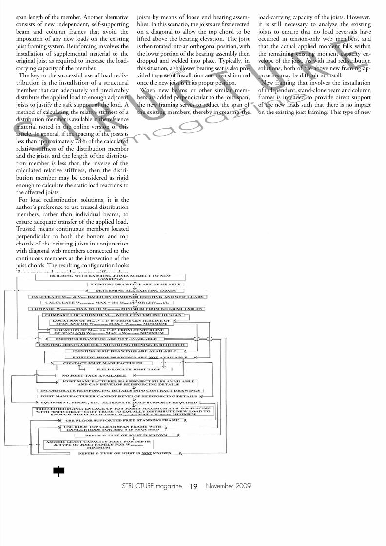
ing joist results in the need to modify thestructural system to provide for the supportof new imposed loads. At this juncture, theengineer must then determine if he or sheis more comfortable with assuming the re-sponsibility and liability for modifying a pre-engineered product or employing a possiblyless risky option, such as load redistributionor adding new joist or beam framing. To assiststructural engineers with the evaluation andmodification process, the author has included acopy of a flowchart (Figure 2, page 19 ) that was developed as result of numerous proj-ects that involved existing joists.▪
D. Matthew Stuart, P.E., S.E., F. ASCE,SECB is licensed in 20 states. Mattcurrently works as a Senior Project Managerat the main office of CMX located in New Jersey, and also serves as Adjunct Professor for the Masters of Structural EngineeringProgram at Lehigh University, Bethlehem,PA. Mr. Stuart may be contacted [email protected].
References80 Years of Open Web Steel Joist Construction A Compilation of Specifications and Load Tables Since 1928Steel Joist InstituteMyrtle Beach, South Carolina 2009
Catalog of Standard Specifications, Load Tables and Weight Tables for Steel Joists and JoistGirders 42nd EditionSteel Joist InstituteMyrtle Beach, South Carolina 2007
Technical Digest No. #12Evaluation and Modification of Open Web Steel Joists and Joist Girders Steel Joist InstituteMyrtle Beach, South Carolina 2007
Designing with Steel Joists, Joist Girders and Steel Deck James Fisher, Michael West, Julius Van de PasNucor Corporation1991 (Second Edition – 2002)
Miscellaneous Steel Joist and Joist Girder Specifications and Load TablesSJI ArchivesSteel Joist Institute, Technology, Engineering, and Education CenterMyrtle Beach, South Carolina
Joist Investigation Formwww.steeljoist.org/investigationSteel Joist InstituteMyrtle Beach, South Carolina