Embed Size (px)
Citation preview
ANTIMATTER-INITIATED MICROFISSION/ FUSION: CONCEPT, MISSIONS, AND SYSTEMS STUDIES FOR EXPLORATION OF DEEP SPACE
G.A. Smith1•2
, K.J. Kramer1"3
, and K.J. Meyer1
1Synergistic Technologies Corporation Los Alamos, New Mexico 87544, (505) 661-4949
2 Propulsion Engineering Research Center, Pennsylvania State University, University Park, PA 16802
3 NASA GSRP Fellow, Propulsion Engineering Research Center and Department of Mechanical Engineering,
Pennsylvania State University, University Park, PA 16802
Abstract
The energy released by antimatter annihilation is 180 MJ/J.tg, greater than that of fusion, fission, and chemical combustion. From a space mission point-ofview, this is exceptional because it implies a propellant source that may have little appreciable mass. Nevertheless, the antiproton ( P ) mass required for beamed-core annihilation engines for deep space missions may be several kilograms, which exceeds current production capabilities (14 ng/yr) by over ten orders of magnitude. Here, we present two concepts, which are a hybrid of antimatter and fusion technologies. The inclusion of the fusion aspect can reduce P requirements to 1-1 00 J..l.g, which may be obtainable in the near future. Also discussed is a propulsion experiment using only 5 x 1 09 antiprotons, which will validate several antimatter-initiated microfission/fusion objectives.
1. Introduction
Throughout the latter half of the 20th century, the world has obtained access to the majority of planets within the Solar System. The lifetimes of five to ten years for such unmanned missions (e.g. Viking, Mariner, Voyager, Galileo, Cassini) were comfortably met through the use of chemical propellants, due to a combination of short mission ranges and payload masses below ten metric tons. However, manned investigations to other planets and scientific inquiries to the Heliopause at 200 AU and beyond have not been est(lblished. Short-duration manned interplanetary missions required exceptional thrust and moderate lsp > I 000 sec., and exceptional specific impulses beyond I 0,000 seconds were necessary for unmanned, precursor-interstellar missions. These were beyond the capabilities of chemical propellants, which is currently limited to about 450 sec. 1
Copyright © 200 I by the Space Studies Institute. All rights reserved.
69
The energy density yielded from various chemical and nuclear reactions is a key of measuring its performance. Indeed, the energy released from chemical combustion is seven orders of magnitude below that of nuclear fission or fusion, and ten orders of magnitude below that of antimatter annihilation. 2
Antimatter annihilation presents the highest energy density known in existence, which is 180 MJ/j.!g. In fact, antiproton-proton annihilation can provide an Isp = 107 sec, which is sufficient enough for pure, interstellar missions. However, the quantity of antimatter required for such an interstellar spacecraft range from 1 to 1000 kilograms, exceeding current antiproton production capabilities of 14 ng/year by at least ten orders of magnitude.
For the scope of the missions presented above, the required Isp ranges from 1 03 to I 05 seconds. Extra Isp can be sacrificed in favor of greater thrust and reduced onboard antimatter. Methods of tailoring desired thrust and Isp from antimatter annihilation have been developed. One important concept, AntimatterCatalyzed Microfission!Jusion (ACMF), can reduce mass estimates to ten micrograms.3 ACMF-based concepts are suitable for interplanetary missions. Another concept, Antimatter-Initiated Microfusion (AIM), is better suited for the precursor-interstellar regime, between 200-10,000 AU.4 Missions utilizing AIM may reach the Oort Cloud at 10,000 AU within fifty years.
2. Antimatter-Catalyzed Microfission/fusion (ACMF)
The concept of using antimatter to initiate nuclear fission is well understood. In 1992 members of the Laboratory for Elementary Particle Science at Penn State University observed large fission and neutron yields from antiproton annihilation at rest in a natural
uranium target. 5 Calculations indicate that short bursts of antiprotons could induce temperatures of several keV in a small compressed pellet.6 These conditions are appropriate for ignition of a hydrogen fusion burn within the microsphere. Targets with yields up to 302 GJ are considered; with compression provided by light ion beams or lasers. Baseline parameters for ignition are: antiproton energy, 1.2 MeV; number, 10 11
; pulse length, 2 ns; and deposition volume, 1 mm3
•
Most of the energy from the microfission/fusion process is in the form of radiation and hot (35 keV average temperature) plasma. Energy is produced in a target consisting of about 3.0 g of nuclear fuel. The nuclear fuel is in a molar ratio of 9:1 of DT:U(235). Initially, the proportions of energy produced in the target are 83% radiation, 15% neutron kinetic energy, and 2% random ion and electron kinetic energy.
Since most of the energy is in the form of high energy radiation, a high Z material (WLS) is desired to absorb and reradiate at lower frequencies (temperatures). The purpose of this is to optimize ablation of a thruster shell exposed to this radiation. The WLS (wavelength shifter) is a spherical shell of 200 g of lead, which has a K-shell absorption edge near the peak of 115 keV for a spectrum with an average temperature of 35 keV. Of the 302 GJ of energy generated in the target, 247 GJ is absorbed by the WLS. This energy is distributed over the WLS volume according to a stellar photosphere modei,1 initially 5.6 keV at the center and 2.3 keV at the surface. Since only a thin skin on the surface of the shell radiates, most of the lead is near the 5.6 KeV temperature, which corresponds to an ionization level of Z*=75. This temperature is not high enough to remove inner shell electrons, thus enabling continuing K-shell absorption of radiation. Energy distributions of photons radiated from the photosphere around the WLS show a very significant shift of radiation down to a mean value of about 1 ke V energy (204 GJ).
3. Antimatter-Initiated Microfusion (AIM)
Physicists have been working for fifty years in an attempt to "spark" fusion fuel into a significant burn. ICF experiments use short pulses of intense laser or particle beams to compress and heat targets by ablation of surrounding materials. Using intense magnetic fields, MCF experiments attempt to continuously compress and heat fusion fuel into a burn. In general, results to date have been measurable, but incomplete, burns of the target material. Inefficient coupling of beams to the target, and plasma instabilities have been largely responsible for the failure for full ignition.
70
These experiments have generally attempted fusion of hydrogen isotopes deuterium (D) and tritium (T), which has a low ignition temperature. The fusion reaction:
D + T ~ n(14.1 MeV) + a(3.5 MeV), (1)
presents serious problems for space applications: (1) large amounts of radioactive tritium are required. From space transportation safety considerations, this requires special shielding; (2) the neutrons require absorbers if their energy is to be used to heat propellant, and (3) if not fully shielded, the neutrons will cause severe radiation damage to the engine and payload. In all, the additional weight required may be at least 1 Tonne, which would be intolerable for a small, fast interstellar probe. The DHe3 reaction,
D + He3 ~ p(14.7 MeV)+ a(3.6 MeV), (2)
is aneutronic, provided the fuel is burned at a sufficiently high temperature so that the competing D + D ~ n + He3 fusion rate is insignificant. Future AIM illustrations use DHe3 as the fusion fuel.
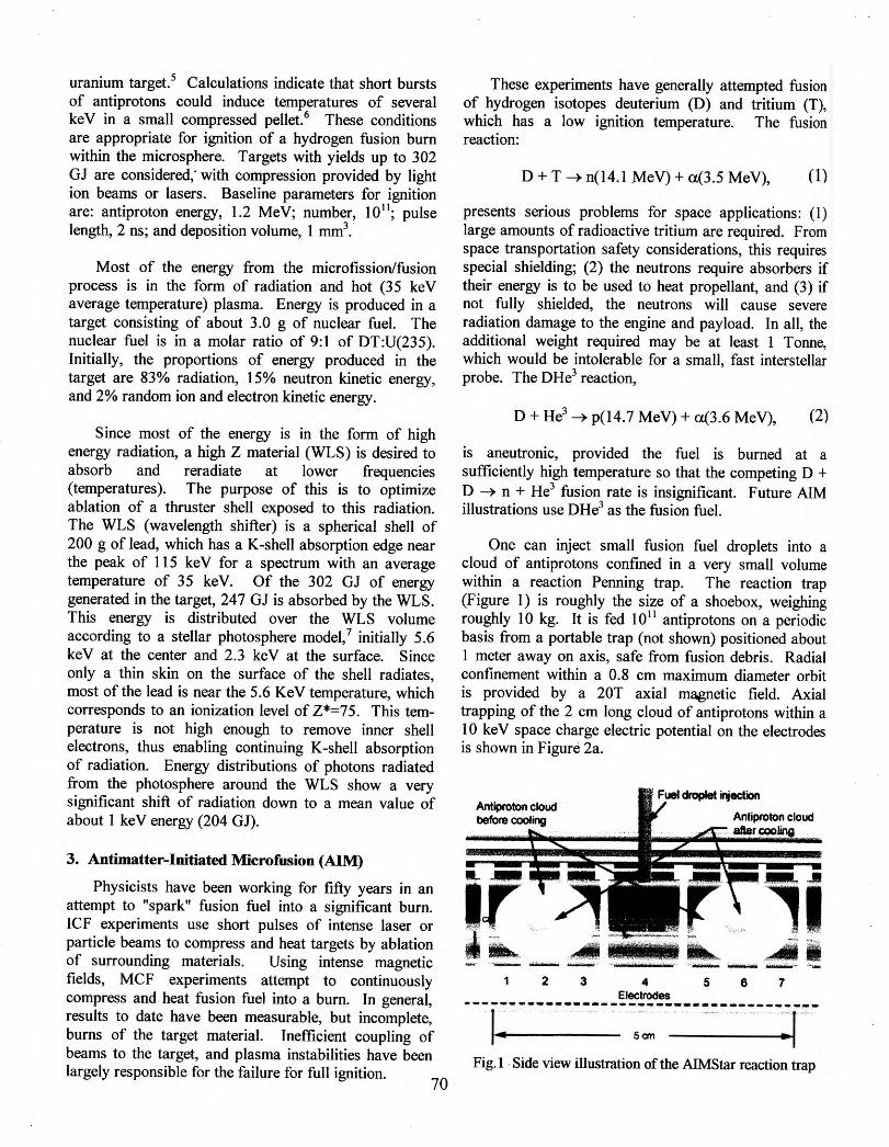
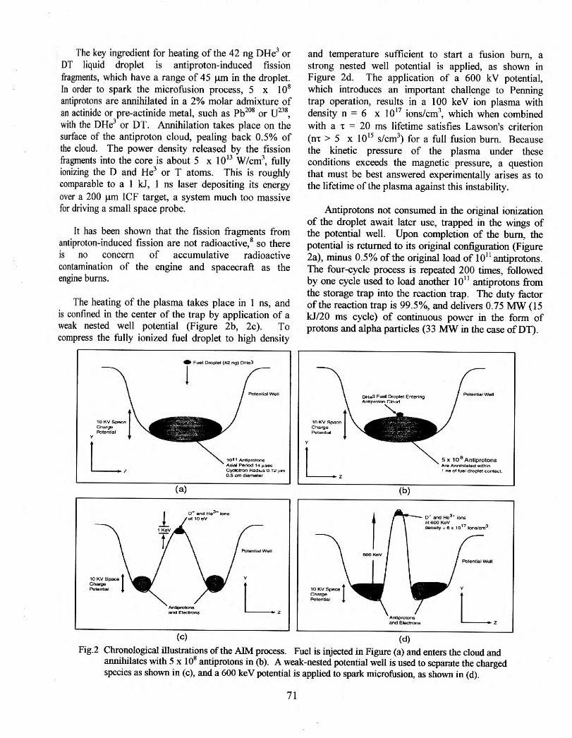
One can inject small fusion fuel droplets into a cloud of antiprotons confined in a very small volume within a reaction Penning trap. The reaction trap (Figure 1) is roughly the size of a shoebox, weighing roughly 10 kg. It is fed 10 11 antiprotons on a periodic basis from a portable trap (not shown) positioned about 1 meter away on axis, safe from fusion debris. Radial confinement within a 0.8 em maximum diameter orbit is provided by a 20T axial magnetic field. Axial trapping of the 2 em long cloud of antiprotons within a 10 keV space charge electric potential on the electrodes is shown in Figure 2a.
2 3 .. 5 6 7 Electrodes
---------------------------------------Scm
Fig. I . Side view illustration of the AIMS tar reaction trap
The key ingredient for heating of the 42 ng DHe3 or DT liquid droplet is antiproton-induced fission fragments, which have a range of 45 f..i.m in the droplet. In order to spark the microfusion process, 5 x 10⁸
antiprotons are annihilated in a 2% molar admixture of . 'd . 'd I h Pb208 U238 an acttm e or pre-actmt e meta , sue as or ,
with the DHe3 or DT. Annihilation takes place on the surface of the antiproton cloud, pealing back 0.5% of the cloud. The power density released by the fission fragments into the core is about 5 x 10¹³ W/cm3
, fully ionizing the D and He3 or T atoms. This is roughly comparable to a 1 kJ, 1 ns laser depositing its energy over a 200 f..i.m ICF target, a system much too massive for driving a small space probe.
It has been shown that the fission fragments from antiproton-induced fission are not radioactive, 8 so there is no concern of accumulative radioactive contamination of the engine and spacecraft as the engine burns.
The heating of the plasma takes place in 1 ns, and is confined in the center of the trap by application of a weak nested well potential (Figure 2b, 2c). To compress the fully ionized fuel droplet to high density
• F""l O<oplet (42 ng) OHe3
1
(a)
Andpn>tono and Elecuona.
(c)
1011 Antif)roton• Axial Petiod 14J.1Soee {..)dotron H8d nJS o . 1:.:! ~m 0-5 em diametM
y
L.
and temperature sufficient to start a fusion burn, a strong nested well potential is applied, as shown in Figure 2d. The application of a 600 kV potential, which introduces an important challenge to Penning trap operation, results in a 100 keY ion plasma with density n = 6 x 10¹⁷ ions/cm3
, which when combined with a • = 20 ms lifetime satisfies Lawson's criterion (m > 5 x 10¹⁵ s/cm3
) for a full fusion burn. Because the kinetic pressure of the plasma under these conditions exceeds the magnetic pressure, a question that must be best answered experimentally arises as to the lifetime of the plasma against this instability.
Antiprotons not consumed in the original ionization of the droplet await later use, trapped in the wings of the potential well. Upon completion of the bum, the potential is returned to its original configuration (Figure 2a), minus 0.5% of the original load of 1011 antiprotons. The four-cycle process is repeated 200 times, followed by one cycle used to load another 1011 antiprotons from the storage trap into the reaction trap. The duty factor ofthe reaction trap is 99.5%, and delivers 0.75 MW (15 kJ/20 rns cycle) of continuous power in the form of protons and alpha particles (33 MW in the case ofDT).
y
(b)
5 x 10⁸ Antiprotons .Are An nihilated within 1 ns of fuel d ropte1 contoc:t.
r-'1--- 0 1 and He
3' ions
Ar'ltlprotons and Electrons
(d)
=1y ~~ x 10 17 tonstcm3
y
L. Fig.2 Chronological illustrations of the AIM process. Fuel is injected in Figure (a) and enters the cloud and
annihilates with 5 x 10⁸ antiprotons in (b). A weak-nested potential well is used to separate the charged species as shown in (c), and a 600 keV potential is applied to spark microfusion, as shown in (d).
71
4. Mission Examples
4.1 ICAN-11 (Interplanetary Spacecraft)
ICAN-11 implements the ACMF concept. The spacecraft is equipped with an adequate shock absorbing apparatus and a means of safely intercepting debris from a nuclear explosion to use the explosion energy derived from ACMF to propel the craft at both high thrust and high Isp. Historically, the first serious effort at this type of propulsion was the ORION pusherplate system. Other sophisticated systems employ a polyethlyene canopy tethered to a winch (MEDUSA), as proposed by J. Solem.9
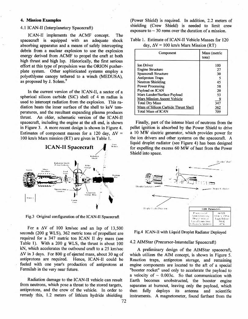
In the current version of the ICAN-11, a sector of a spherical silicon carbide (SiC) shell of 4 m radius is used to intercept radiation from the explosion. This radiation heats the inner surface of the shell to keY temperatures, and the resultant expanding plasma produces thrust. An older, schematic version of the ICAN-11 spacecraft, including the engine at the aft end, is shown in Figure 3. A more recent design is shown in Figure 4. Estimates of component masses for a 120 day, !lV = 100 km/s Mars mission (RT) are given in Table 1.
I ·· ~, .. - 1
ICAN-11 Spacecraft A· ,:.~,~,. N .a\1•-tl~+•n ''"""., l'•t"ll'l ( 'o•lh•,lott
l f\ol
N.ertimi .. u 'hhltl
Fig.3 Original configuration ofthe ICAN-II Spacecraft
For a !lV of 100 km/sec and an Isp of 13,500 seconds (200 g WLS ), 362 metric tons of propellant are required for a 347 metric ton ICAN II dry mass (see Table 1 ). With a 200 g WLS, the thrust is about 100 kN, which accelerates the outbound craft to a 25 km/sec !l V in 3 days. For 800 g of ejected mass, about 30 ng of antiprotons are required. Hence, ICAN-11 could be fueled with one year's production of antiprotons at F ermilab in the very near future.
Radiation damage to the ICAN-11 vehicle can result from neutrons, which pose a threat to the stored targets, antiprotons, and the crew of the vehicle. In order to remedy this, 1.2 meters of lithium hydride shielding
72
(Power Shield) is required. In addition, 2.2 meters of shielding (Crew Shield) is needed to limit crew exposure to - 30 rems over the duration of a mission.
Table 1. Estimate ofiCAN-11 Vehicle Masses for 120 day, !lV = 100 km/s Mars Mission (RT)
Component Mass (metric tons)
Ion Driver 100 Engine Structure 27 Spacecraft Structure 30 Antiproton Traps 5 Neutron Shielding 45 Power Processing 58 Payload on ICAN 20 Mars Lander/Surface Payload 53 Mars Mission Ascent Vehicle _2 Total Dry Mass 347 Mass of Silicon Carbide Thrust Shell 362 Total Mass ofiCAN 709
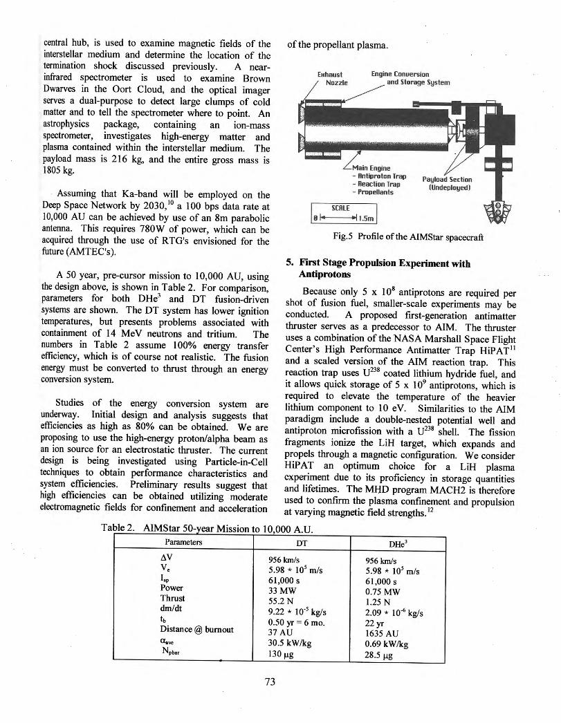
Finally, part ofthe intense blast of neutrons from the pellet ignition is absorbed by the Power Shield to drive a 10 MW electric generator, which provides power for the ion drivers and other systems on the spacecraft. A liquid droplet radiator (see Figure 4) has been designed for expelling the excess 60 MW of heat from the Power Shield into space.
• I ~------
~~J~, -~ . ._' ---. . . ·~ ·..:.....-
l ~· ··- - · -· .• .-: ~ :::J.._..; i; i .· ~ ~
~'·' •'• 1 .· ,,·, ;nl 1111 \!\\ \ ;v,-r• •-.inu·~· ~''"' !•lm ' J•,.t u1 I h · •(:: :u ,1,: .• 1 l.n,,td l•thnw l
L:l.'l :.-.1 :~·:n t.._.,;,ll ·h' .;;;.;•) t\ ( " ltl·, 1, .! kt~ lJ'•·r:.tlll'l ' ...l~.:"' h:
Fig.4 ICAN-11 with Liquid Droplet Radiator Deployed
4.2 AIMStar (Precursor-Interstellar Spacecraft)
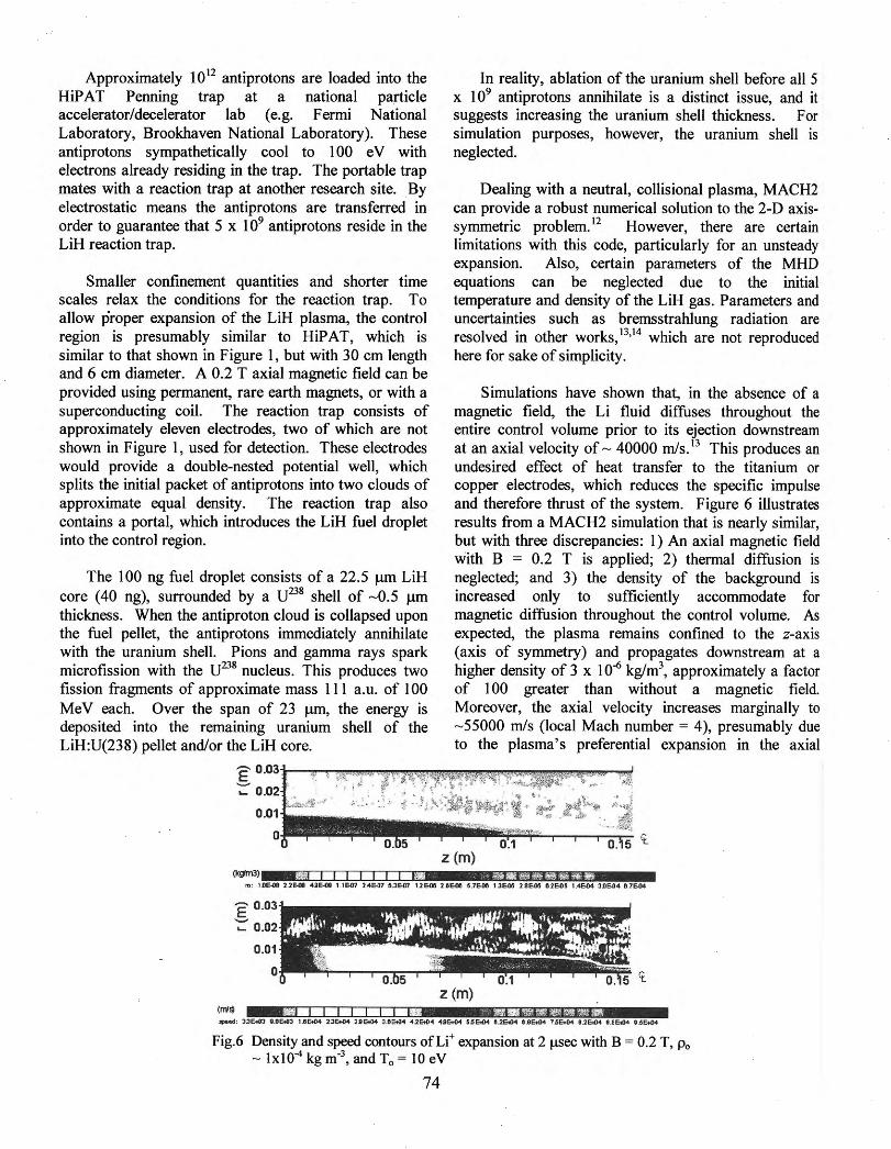
A preliminary design of the AIMStar spacecraft, which utilizes the AIM concept, is shown in Figure 5. Reaction traps, antiproton storage, and remaining engine components are located to the aft of a special "booster rocket" used only to accelerate the payload to a velocity of - 0.003c. So that communication with Earth becomes unobstructed, the booster engine separates at burnout, leaving only the payload, which then fully deploys its antenna and scientific instruments. A magnetometer, found farthest from the
central hub, is used to examine magnetic fields of the interstellar medium and determine the location of the termination shock discussed previously. A nearinfrared spectrometer is used to examine Brown Dwarves in the Oort Cloud, and the optical imager serves a dual-purpose to detect large clumps of cold matter and to tell the spectrometer where to point. An astrophysics package, containing an ion-mass spectrometer, investigates high-energy matter and plasma contained within the interstellar medium. The payload mass is 216 kg, and the entire gross mass is 1805 kg.
Assuming that Ka-band will be employed on the Deep Space Network by 2030, 10 a 100 bps data rate at I 0,000 AU can be achieved by use of an 8m parabolic antenna. This requires 780W of power, which can be acquired through the use of R TG's envisioned for the future (AMTEC's ).
A 50 year, pre-cursor mission to 10,000 AU, using the design above, is shown in Table 2. For comparison, parameters for both DHe3 and DT fusion-driven systems are shown. The DT system has lower ignition temperatures, but presents problems associated with containment of 14 MeV neutrons and tritium. The numbers in Table 2 assume 100% energy transfer efficiency, which is of course not realistic. The fusion energy must be converted to thrust through an energy conversion system.
Studies of the energy conversion system are underway. Initial design and analysis suggests that efficiencies as high as 80% can be obtained. We are proposing to use the high-energy proton/alpha beam as an ion source for an electrostatic thruster. The current design is being investigated using Particle-in-Cell techniques to obtain performance characteristics and system efficiencies. Preliminary results suggest that high efficiencies can be obtained utilizing moderate electromagnetic fields for confinement and acceleration
of the propellant plasma.
Engine Conuersion and Storage System
Main Engine - Antiproton Trap - Reaction Trap - Propellants
I SCALE I Bl• ..j I.Sm .
Payload Section (Undeployed)
Fig.5 Profile of the AIMStar spacecraft
5. First Stage Propulsion Experiment with Antiprotons
Because only 5 x 1 08 antiprotons are required per shot of fusion fuel, smaller-scale experiments may be conducted. A proposed first-generation antimatter thruster serves as a predecessor to AIM. The thruster uses a combination of the NASA Marshall Space Flight Center's High Performance Antimatter Trap HiPAT 11
and a scaled version of the AIM reaction trap. This reaction trap uses U238 coated lithium hydride fuel, and it allows quick storage of 5 x 10⁹ antiprotons, which is required to elevate the temperature of the heavier lithium component to 10 eV. Similarities to the AIM paradigm include a double-nested potential well and antiproton rnicrofission with a U238 shell. The fission fragments ionize the LiH target, which expands and propels through a magnetic configuration. We consider HiPAT an optimum choice for a LiH plasma experiment due to its proficiency in storage quantities and lifetimes. The MHO program MACH2 is therefore used to confirm the plasma confinement and propulsion at varying magnetic field strengths. 12
Tabl 2 AIMSt 50 e ar ::.r_ear M" . to 10 000 A U ISS JOn '
Parameters DT DHe3
AV 956 km/s 956 km/s v. 5.98 * 105 m/s 5.98 * 105 m/s lsp 61 ,000 s 61 ,000 s Power 33MW 0.75 MW Thrust 55.2 N 1.25 N dm/dt 9.22 * 10·5 kg/s 2.09 * 10·6 kg/s tb 0.50 yr = 6 mo. 22 yr Distance @ burnout 37 AU 1635 AU a..ve 30.5 kW/kg 0.69 kW/kg Npbar 130 J.Lg 28.5 J.Lg
73
Approximately 1012 antiprotons are loaded into the HiP AT Penning trap at a national particle accelerator/decelerator lab (e.g. Fermi National Laboratory, Brookhaven National Laboratory). These antiprotons sympathetically cool to 100 eV with electrons already residing in the trap. The portable trap mates with a reaction trap at another research site. By electrostatic means the antiprotons are transferred in order to guarantee that 5 x 1 09 antiprotons reside in the LiH reaction trap.
Smaller confinement quantities and shorter time scales relax the conditions for the reaction trap. To allow proper expansion of the LiH plasma, the control region is presumably similar to HiPAT, which is similar to that shown in Figure I, but with 30 em length and 6 em diameter. A 0.2 T axial magnetic field can be provided using permanent, rare earth magnets, or with a superconducting coil. The reaction trap consists of approximately eleven electrodes, two of which are not shown in Figure 1, used for detection. These electrodes would provide a double-nested potential well, which splits the initial packet of antiprotons into two clouds of approximate equal density. The reaction trap also contains a portal, which introduces the LiH fuel droplet into the control region.
The I 00 ng fuel droplet consists of a 22.5 J.lm LiH core ( 40 ng), surrounded by a U238 shell of -0.5 J.lm thickness. When the antiproton cloud is collapsed upon the fuel pellet, the antiprotons immediately annihilate with the uranium shell. Pions and gamma rays spark microfission with the U238 nucleus. This produces two fission fragments of approximate mass 111 a.u. of 100 MeV each. Over the span of 23 J.lm, the energy is deposited into the remaining uranium shell of the LiH:U(238) pellet and/or the LiH core.
In reality, ablation of the uranium shell before all 5 x 1 09 antiprotons annihilate is a distinct issue, and it suggests increasing the uranium shell thickness. For simulation purposes, however, the uranium shell is neglected.
Dealing with a neutral, collisional plasma, MACH2 can provide a robust numerical solution to the 2-D axissymmetric problem. 12 However, there are certain limitations with this code, particularly for an unsteady expansion. Also, certain parameters of the MHD equations can be neglected due to the initial temperature and density of the LiH gas. Parameters and uncertainties such as bremsstrahlung radiation are resolved in other works, 13•
14 which are not reproduced here for sake of simplicity.
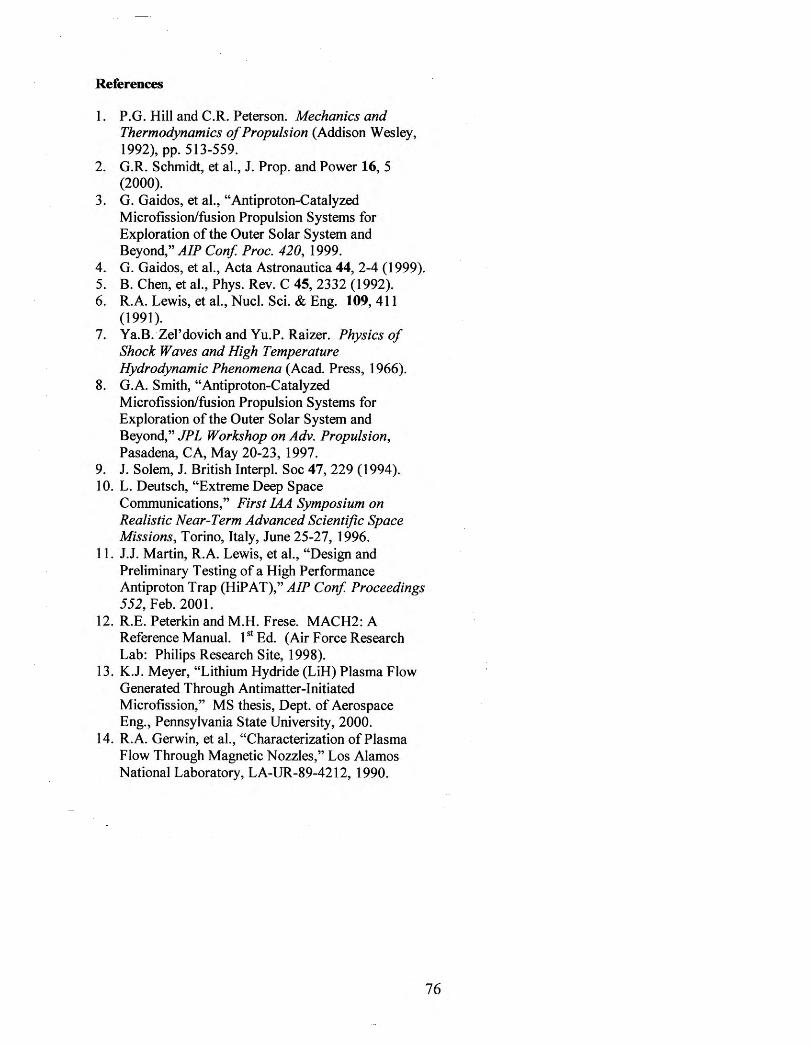
Simulations have shown that, in the absence of a magnetic field, the Li fluid diffuses throughout the entire control volume prior to its ejection downstream at an axial velocity of- 40000 rnls. 13 This produces an undesired effect of heat transfer to the titanium or copper electrodes, which reduces the specific impulse and therefore thrust of the system. Figure 6 illustrates results from a MACH2 simulation that is nearly similar, but with three discrepancies: 1) An axial magnetic field with B = 0.2 T is applied; 2) thermal diffusion is neglected; and 3) the density of the background is increased only to sufficiently accommodate for magnetic diffusion throughout the control volume. As expected, the plasma remains confined to the z-axis (axis of symmetry) and propagates downstream at a higher density of 3 x I 0-6 kg/m3
, approximately a factor of I 00 greater than without a magnetic field. Moreover, the axial velocity increases marginally to - 55000 rnls (local Mach number = 4), presumably due to the plasma' s preferential expansion in the axial
.1 0 . 5 't. z (m)
m: IOE-08 2.2Ea 4AE-OI US-07 2.46-07 5.36-07 1l6ll8 216(18 5,7S08 13&ll5 2.86-05 fllE-tl 5 L46G4 306-04 87£04
z (m)
Fig.6 Density and speed contours ofLi+ expansion at 2 J.lSec with B = 0.2 T, Po - lxl04 kg m-3, and T0 = 10 eV
74
References
I. P.G. Hill and C.R. Peterson. Mechanics and Thermodynamics of Propulsion (Addison Wesley, 1992), pp. 513-559.
2. G.R. Schmidt, et al., J. Prop. and Power 16, 5 (2000).
3. G. Gaidos, et al., "Antiproton-Catalyzed Microfission/fusion Propulsion Systems for Exploration of the Outer Solar System and Beyond," AlP Conf. Proc. 420, 1999.
4. G. Gaidos, et al., Acta Astronautica 44, 2-4 (1999). 5. B. Chen, et al., Phys. Rev. C 45, 2332 (1992). 6. R.A. Lewis, et al., Nucl. Sci. & Eng. 109, 411
(1991). 7. Ya.B. Zel'dovich and Yu.P. Raizer. Physics of
Shock Waves and High Temperature Hydrodynamic Phenomena (Acad. Press, 1966).
8. G.A. Smith, "Antiproton-Catalyzed Microfission/fusion Propulsion Systems for Exploration of the Outer Solar System and Beyond," JPL Workshop on Adv. Propulsion, Pasadena, CA, May 20-23, 1997.
9. J. Solem, J. British Interpl. Soc 47, 229 (1994). 10. L. Deutsch, "Extreme Deep Space
Communications," First lAA Symposium on Realistic Near-Term Advanced Scientific Space Missions, Torino, Italy, June 25-27, 1996.
1 1. J.J. Martin, R.A. Lewis, et al., "Design and Preliminary Testing of a High Performance Antiproton Trap· (HiP AT)," AlP Conf Proceedings 552, Feb. 2001.
12. R.E. Peterkin and M.H. Frese. MACH2: A Reference Manual. I 51 Ed. (Air Force Research Lab: Philips Research Site, 1998).
13. K.J. Meyer, "Lithium Hydride (LiH) Plasma Flow Generated Through Antimatter-Initiated Microfission," MS thesis, Dept. of Aerospace Eng., Pennsylvania State University, 2000.
14. R.A. Gerwin, et al., "Characterization of Plasma Flow Through Magnetic Nozzles," Los Alamos National Laboratory, LA-UR-89-4212, 1990.
76


![Antimatter [media art]](https://img.pdfslide.us/doc/110x75/586e15101a28ab8b3b8b8049/antimatter-media-art.jpg)