Embed Size (px)
Citation preview
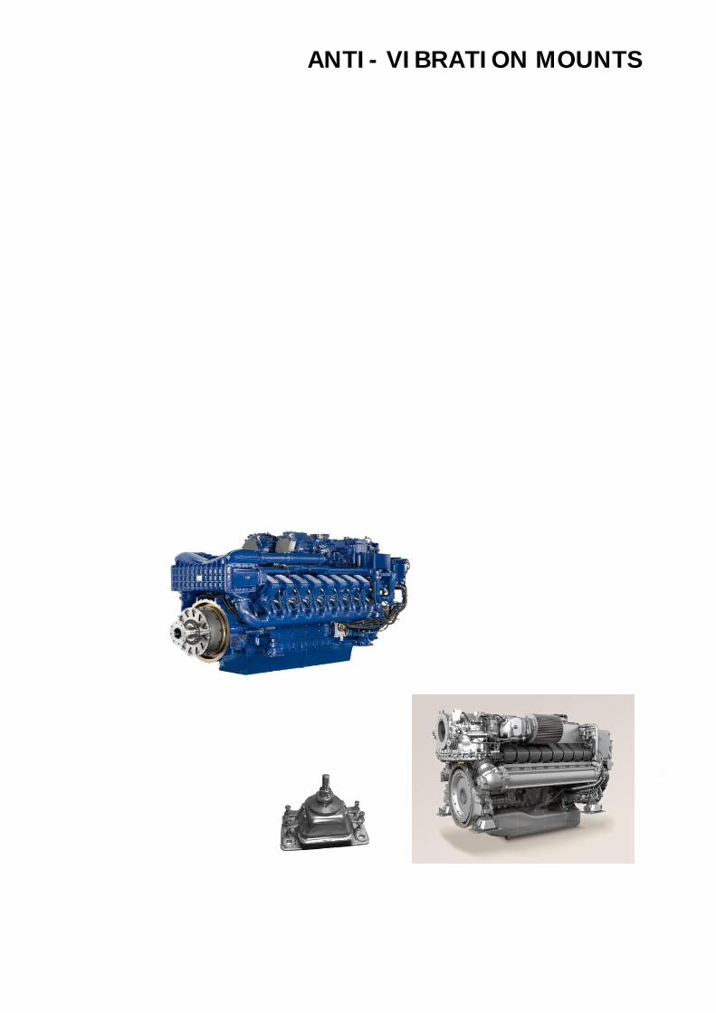
ANTI VIBRATION MOUNTS
MOUNTSPRODUKTBEISPIELEPRODUCTS
Insulators
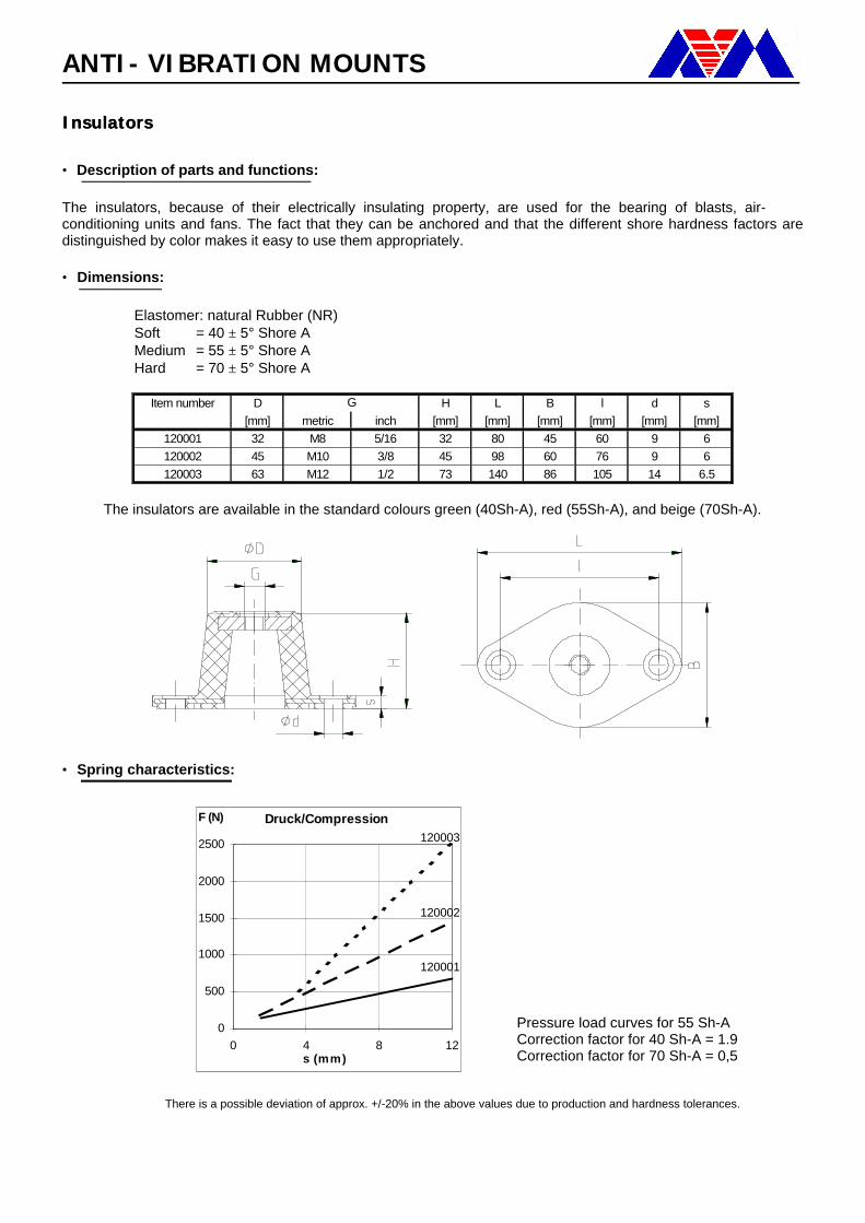
• Description of parts and functions: The insulators, because of their electrically insulating property, are used for the bearing of blasts, air-conditioning units and fans. The fact that they can be anchored and that the different shore hardness factors are distinguished by color makes it easy to use them appropriately. • Dimensions:
Elastomer: natural Rubber (NR) Soft = 40 ± 5° Shore A Medium = 55 ± 5° Shore A Hard = 70 ± 5° Shore A
Item number D H L B l d s
[mm] metric inch [mm] [mm] [mm] [mm] [mm] [mm]120001 32 M8 5/16 32 80 45 60 9 6120002 45 M10 3/8 45 98 60 76 9 6120003 63 M12 1/2 73 140 86 105 14 6.5
G
The insulators are available in the standard colours green (40Sh-A), red (55Sh-A), and beige (70Sh-A).
• Spring characteristics:
Pressure load curves for 55 Sh-A Correction factor for 40 Sh-A = 1.9 Correction factor for 70 Sh-A = 0,5
There is a possible deviation of approx. +/-20% in the above values due to production and hardness tolerances.
Druck/Compression
0
500
1000
1500
2000
2500
0 4 8 12s (mm)
F (N)
120001
120002
120003
ANTI VIBRATION MOUNTS
Insulators
Machine Mount
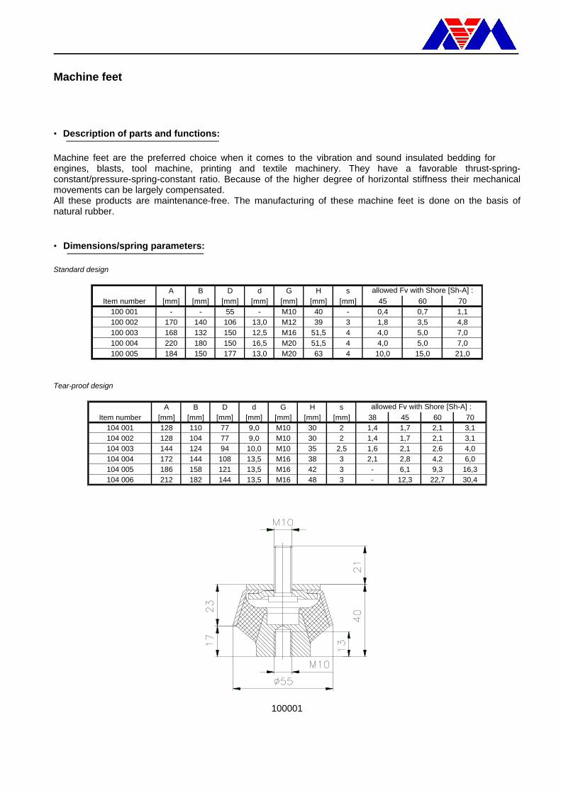
• Description of parts and functions: Machine feet are the preferred choice when it comes to the vibration and sound insulated bedding for engines, blasts, tool machine, printing and textile machinery. They have a favorable thrust-spring-constant/pressure-spring-constant ratio. Because of the higher degree of horizontal stiffness their mechanical movements can be largely compensated. All these products are maintenance-free. The manufacturing of these machine feet is done on the basis of natural rubber. • Dimensions/spring parameters: Standard design
A B D d G H sItem number [mm] [mm] [mm] [mm] [mm] [mm] [mm] 45 60 70
100 001 - - 55 - M10 40 - 0,4 0,7 1,1100 002 170 140 106 13,0 M12 39 3 1,8 3,5 4,8100 003 168 132 150 12,5 M16 51,5 4 4,0 5,0 7,0100 004 220 180 150 16,5 M20 51,5 4 4,0 5,0 7,0100 005 184 150 177 13,0 M20 63 4 10,0 15,0 21,0
allowed Fv with Shore [Sh-A] :
Tear-proof design
A B D d G H sItem number [mm] [mm] [mm] [mm] [mm] [mm] [mm] 38 45 60 70
104 001 128 110 77 9,0 M10 30 2 1,4 1,7 2,1 3,1104 002 128 104 77 9,0 M10 30 2 1,4 1,7 2,1 3,1104 003 144 124 94 10,0 M10 35 2,5 1,6 2,1 2,6 4,0104 004 172 144 108 13,5 M16 38 3 2,1 2,8 4,2 6,0104 005 186 158 121 13,5 M16 42 3 - 6,1 9,3 16,3104 006 212 182 144 13,5 M16 48 3 - 12,3 22,7 30,4
allowed Fv with Shore [Sh-A] :
100001
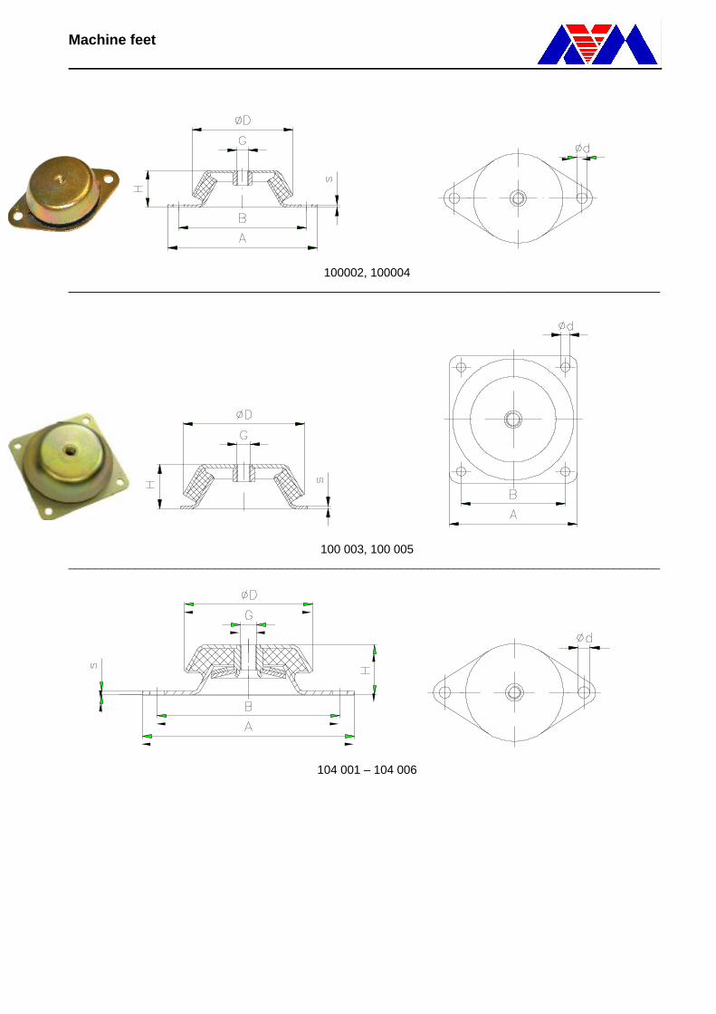
Machine Mount
100002, 100004 _________________________________________________________________________________________
100 003, 100 005 _________________________________________________________________________________________
104 001 – 104 006
Machine Mount
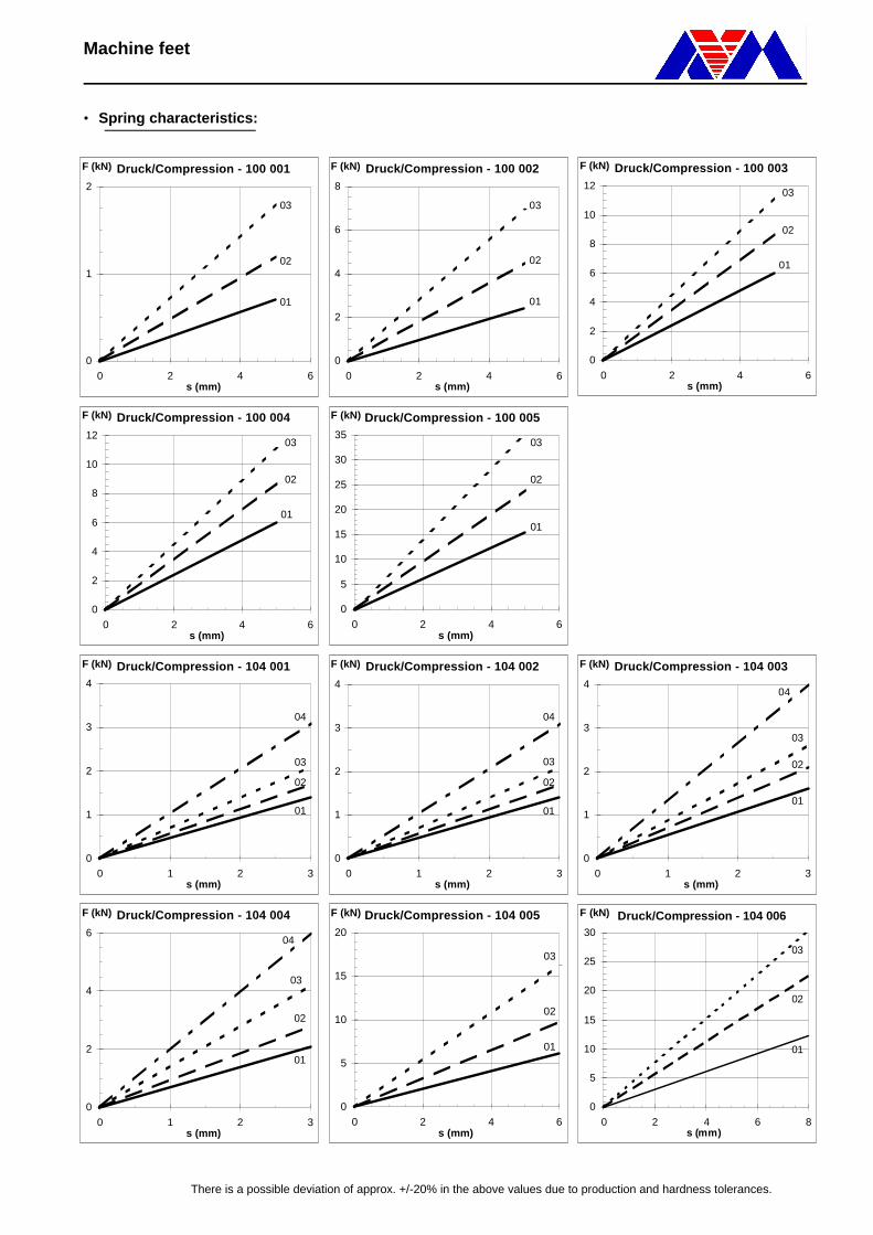
• Spring characteristics:
There is a possible deviation of approx. +/-20% in the above values due to production and hardness tolerances.
Druck/Compression - 100 001
0
1
2
0 2 4 6s (mm)
F (kN)
02
03
01
Druck/Compression - 100 002
0
2
4
6
8
0 2 4 6s (mm)
F (kN)
02
03
01
Druck/Compression - 100 003
0
2
4
6
8
10
12
0 2 4 6s (mm)
F (kN)
02
03
01
Druck/Compression - 100 004
0
2
4
6
8
10
12
0 2 4 6s (mm)
F (kN)
02
03
01
Druck/Compression - 100 005
0
5
10
15
20
25
30
35
0 2 4 6s (mm)
F (kN)
02
03
01
Druck/Compression - 104 001
0
1
2
3
4
0 1 2 3s (mm)
F (kN)
02
03
01
04
Druck/Compression - 104 002
0
1
2
3
4
0 1 2 3s (mm)
F (kN)
02
03
01
04
Druck/Compression - 104 003
0
1
2
3
4
0 1 2 3s (mm)
F (kN)
02
03
01
04
Druck/Compression - 104 004
0
2
4
6
0 1 2 3s (mm)
F (kN)
02
03
01
04
Druck/Compression - 104 005
0
5
10
15
20
0 2 4 6s (mm)
F (kN)
02
03
01
Druck/Compression - 104 006
0
5
10
15
20
25
30
0 2 4 6 8s (mm)
F (kN)
02
03
01
Machine Mount, heightadjustable
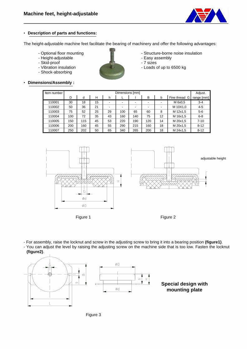
• Description of parts and functions: The height-adjustable machine feet facilitate the bearing of machinery and offer the following advantages: - Optional floor mounting - Structure-borne noise insulation - Height-adjustable - Easy assembly - Skid-proof - 7 sizes - Vibration insulation - Loads of up to 6500 kg - Shock-absorbing • Dimensions/Assembly :
Item number Adjust.D d H h L l B b Fine thread G range [mm]
110001 30 18 15 - - - - - M 6x0,5 3-4110002 50 36 21 - - - - - M 10X1,0 4-5110003 75 52 25 29 100 65 60 8 M 12x1,5 5-6110004 100 72 35 43 160 140 75 12 M 16x1,5 6-8110005 150 115 45 53 220 190 120 14 M 20x1,5 7-10110006 200 160 45 55 290 215 160 18 M 20x1,5 8-12110007 250 202 50 65 340 265 200 18 M 24x1,5 8-12
Dimensions [mm]
Figure 1 Figure 2 - For assembly, raise the locknut and screw in the adjusting screw to bring it into a bearing position (figure1). - You can adjust the level by raising the adjusting screw on the machine side that is too low. Fasten the locknut
(figure2).
Figure 3
Special design with mounting plate
adjustable height
Machine Mount
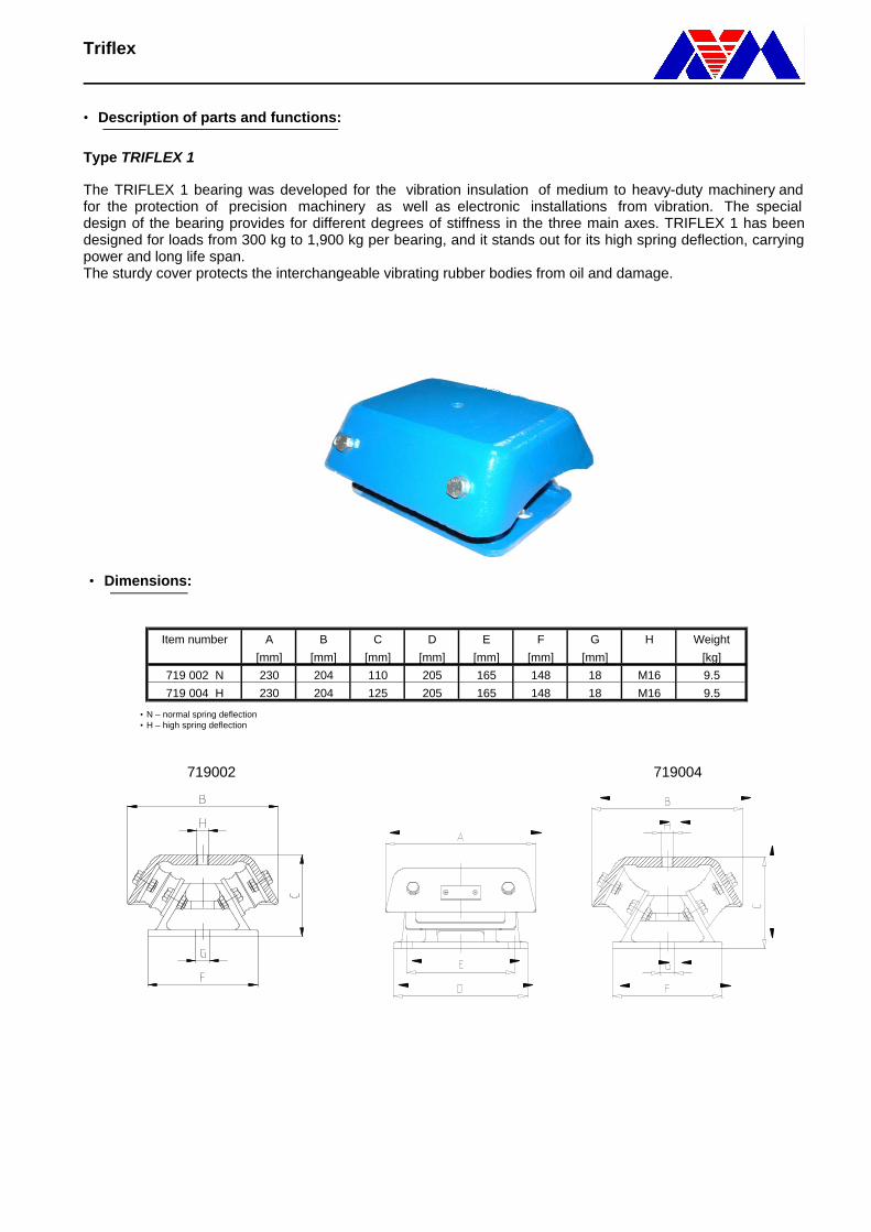
• Description of parts and functions: Type TRIFLEX 1 The TRIFLEX 1 bearing was developed for the vibration insulation of medium to heavy-duty machinery andfor the protection of precision machinery as well as electronic installations from vibration. The special design of the bearing provides for different degrees of stiffness in the three main axes. TRIFLEX 1 has been designed for loads from 300 kg to 1,900 kg per bearing, and it stands out for its high spring deflection, carrying power and long life span. The sturdy cover protects the interchangeable vibrating rubber bodies from oil and damage.
• Dimensions:
Item number A B C D E F G H Weight
[mm] [mm] [mm] [mm] [mm] [mm] [mm] [kg]
719 002 N 230 204 110 205 165 148 18 M16 9.5
719 004 H 230 204 125 205 165 148 18 M16 9.5
• N – normal spring deflection • H – high spring deflection
719002 719004
Machine Mount
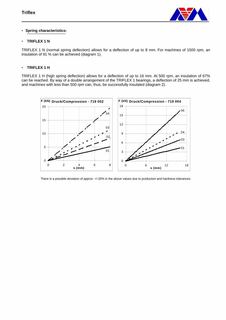
• Spring characteristics: • TRIFLEX 1 N TRIFLEX 1 N (normal spring deflection) allows for a deflection of up to 8 mm. For machines of 1500 rpm, an insulation of 91 % can be achieved (diagram 1). • TRIFLEX 1 H TRIFLEX 1 H (high spring deflection) allows for a deflection of up to 16 mm. At 500 rpm, an insulation of 67% can be reached. By way of a double arrangement of the TRIFLEX 1 bearings, a deflection of 25 mm is achieved, and machines with less than 500 rpm can, thus, be successfully insulated (diagram 2).
There is a possible deviation of approx. +/-20% in the above values due to production and hardness tolerances.
Druck/Compression - 719 002
0
5
10
15
20
0 2 4 6 8s (mm)
F (kN)
01
04
02
03
Druck/Compression - 719 004
0
3
6
9
12
15
18
0 6 12 18s (mm)
F (kN)
01
06
03
04
Machine Mount
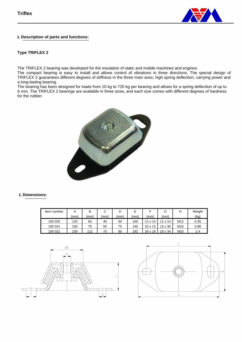
· Description of parts and functions: Type TRIFLEX 2 The TRIFLEX 2 bearing was developed for the insulation of static and mobile machines and engines. The compact bearing is easy to install and allows control of vibrations in three directions. The special design of TRIFLEX 2 guarantees different degrees of stiffness in the three main axes, high spring deflection, carrying power and a long-lasting bearing. The bearing has been designed for loads from 10 kg to 720 kg per bearing and allows for a spring deflection of up to 6 mm. The TRIFLEX 2 bearings are available in three sizes, and each size comes with different degrees of hardness for the rubber.
· Dimensions:
Item number A B C D E F G H Weight
[mm] [mm] [mm] [mm] [mm] [mm] [mm] [kg]
100 020 120 60 40 60 100 11 x 14 11 x 14 M12 0.35
100 021 183 75 50 75 140 20 x 13 13 x 30 M16 0.88
100 022 230 112 70 80 182 26 x 18 18 x 34 M20 2.4
Machine Mount
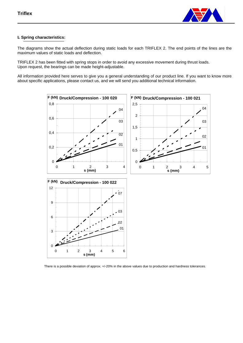
· Spring characteristics: The diagrams show the actual deflection during static loads for each TRIFLEX 2. The end points of the lines are the maximum values of static loads and deflection. TRIFLEX 2 has been fitted with spring stops in order to avoid any excessive movement during thrust loads. Upon request, the bearings can be made height-adjustable. All information provided here serves to give you a general understanding of our product line. If you want to know more about specific applications, please contact us, and we will send you additional technical information.
There is a possible deviation of approx. +/-20% in the above values due to production and hardness tolerances.
Druck/Compression - 100 020
0
0,2
0,4
0,6
0,8
0 1 2 3 4s (mm)
F (kN)
01
03
02
04
Druck/Compression - 100 021
0
0,5
1
1,5
2
2,5
0 1 2 3 4 5s (mm)
F (kN)
01
03
02
04
Druck/Compression - 100 022
0
3
6
9
12
0 1 2 3 4 5 6s (mm)
F (kN)
01
03
02
07

subject to change without prior notice
MF-Mounts
• Description of parts and functions:
MF elements are used for the bedding and structure-borne noise insulation of equipment and aggregatesin mobile or stationary applications, for example in vehicles, ships or airplanes. Thanks to their form-fitting de-sign they are tear-proof. The elastomer and metal parts are not bonded.The MF elements can withstand any load resulting from pressure, tension or thrust. However, their polydirec-tional elasticity also allows for a combination of loads. Their vibration-insulating and shock-absorbing propertiesare effective in a temperature range from – 25°C to + 80°C when a standard elastomer is used; with ahighly damping elastomer that range would even be – 50°C to + 180°C.
Standard material: -zinc-coated metal parts-age and oil-resistant elastomer
• Dimensions:
Item Number a1 a2 b1 b2 d1 d2 d3 d4 h Diagram[mm] [mm] [mm] [mm] [mm] [mm] [mm] [mm] [mm] Shape
155003 28 36 28 36 5,1 20 29 3,3 19,8 1155004 28 36 28 36 M5 20 29 3,3 19,8 1155005 35,8 45,5 - 28,8 5,1 20 - 4,6 19,8 1155006 35,8 45,5 - 28,8 M5 20 - 4,6 19,8 1155007 35,8 45,5 - 28,8 5,1 20 - 4,6 19,8 1155008 35,8 45,5 - 28,8 M4 20 - 4,6 19,8 1155011 35 44,8 35 44,8 6,6 34,6 38 4,3 26 2155012 35 44,8 35 44,8 M8 34,6 38 4,3 26 2155013 35 44,8 35 44,8 6,6 29 38 4,3 26 2155014 35 44,8 35 44,8 M8 29 38 4,3 26 2155018 35 44,8 35 44,8 6,6 29 38 4,8 26 2
Shape 1:
Shape 2:
subject to change without prior notice
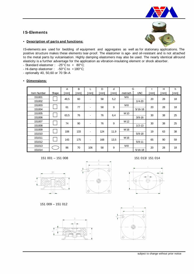
IS-Mounts
• Description of parts and functions:
IS-elements are used for bedding of equipment and aggregates as well as for stationary applications. Thepositive structure makes these elements tear-proof. The elastomer is age- and oil-resistant and is not attachedto the metal parts by vulcanisation. Highly damping elastomers may also be used. The nearly identical allroundelasticity is a further advantage for the application as vibration-insulating element or shock absorber.- Standard elastomer : -25°C to + 80°C;- Hi-damp elastomer : -50°C to +180°C;- optionally 40, 50,60 or 70 Sh-A
• Dimensions:
A B L D d t H hItem Number Shape [mm] [mm] [mm] [mm] [mm] metrisch UNC [mm] [mm] [mm]
151001 M 6151002 1/4-20151003 M 8151004 5/16-18151005 M 10151006 3/8-16151007 M 12151008 1/2-13151009 M 16151010 5/8-18151011 M 16151012 5/8-11151013 M 8151014 5/16-18
G
49,5
61
63,5
-
-
-
74
108
143
86 70
175
60
77
76
90
133 -
-
58
58
76
76
124
168
58106
5,2
9
6,4
9
11,9
13,5
9
-
20
20
30
30
19
65
20
28
28
38
38
63
90
28
38
59
18
18
18
25
25
151 001 – 151 008 151 013/ 151 014
151 009 – 151 012
subject to change without prior notice
Conical Mounts
• Description of parts and functions:
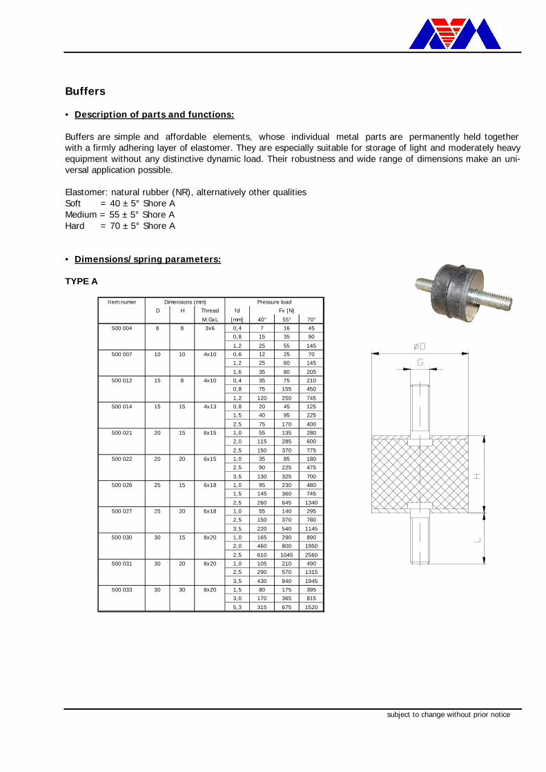
Buffers are simple and affordable elements, whose individual metal parts are permanently held togetherwith a firmly adhering layer of elastomer. They are especially suitable for storage of light and moderately heavyequipment without any distinctive dynamic load. Their robustness and wide range of dimensions make an uni-versal application possible.
Elastomer: natural rubber (NR), alternatively other qualitiesSoft = 40 ± 5° Shore AMedium = 55 ± 5° Shore AHard = 70 ± 5° Shore A
• Dimensions/spring parameters:
TYPE A
Item numerD H Thread fd
M:GxL [mm] 40° 55° 70°500 004 8 8 3x6 0,4 7 16 45
0,8 15 35 90
1,2 25 55 145500 007 10 10 4x10 0,6 12 25 70
1,2 25 60 145
1,6 35 80 205500 012 15 8 4x10 0,4 35 75 210
0,8 75 155 450
1,2 120 250 745500 014 15 15 4x13 0,8 20 45 125
1,5 40 95 225
2,5 75 170 400500 021 20 15 6x15 1,0 55 135 280
2,0 115 285 600
2,5 150 370 775500 022 20 20 6x15 1,0 35 85 180
2,5 90 225 475
3,5 130 325 700500 026 25 15 6x18 1,0 95 230 480
1,5 145 360 745
2,5 260 645 1340500 027 25 20 6x18 1,0 55 140 295
2,5 150 370 780
3,5 220 540 1145500 030 30 15 8x20 1,0 165 290 890
2,0 460 800 1950
2,5 610 1045 2560500 031 30 20 8x20 1,0 105 210 490
2,5 290 570 1315
3,5 430 840 1945500 033 30 30 8x20 1,5 80 175 395
3,0 170 365 815
5,3 315 675 1520
Dimensions (mm) Pressure loadFv [N]

subject to change without prior notice
TYPE B
Item number D H Thread fd
M:GxL [mm] 40° 55° 70°510004 8 8 3x6 0,4 8 18 50
0,8 17 39 991,2 28 61 160
510006 10 10 4x10 0,6 13 28 771,2 28 66 160
1,6 39 88 226510010 15 10 4x10 0,4 39 83 231
0,8 83 171 4951,2 132 275 820
510011 15 15 4x13 0,8 22 50 1381,5 44 105 2482,5 83 187 440
510016 20 15 6x15 1,0 61 149 3082,0 127 314 6602,5 165 407 853
510017 20 20 6x15 1,0 39 94 1982,5 99 248 5233,5 143 358 770
510020 25 15 6x18 1,0 105 253 528
1,5 160 396 8202,5 286 710 1474
510021 25 20 6x18 1,0 61 154 3252,5 165 407 8583,5 242 594 1260
510024 30 15 8x20 1,0 182 319 9792,0 506 880 2145
2,5 671 1150 2816510025 30 20 8x20 1,0 116 231 539
2,5 319 627 14473,5 473 924 2140
510027 30 30 8x20 1,5 88 193 4353,0 187 402 897
5,3 347 743 1672
Dimensions (mm) Pressure loadFv [N]
Type C
Item number Dimensions [mm]D H Thread fd
M:G [mm] 40° 55° 70°520001 8 8 3 0,1 11 23 46
0,2 24 48 980,4 56 109 222
520003 10 10 4 0,1 24 46 940,2 52 99 1990,4 121 228 458
520007 15 15 4 0,5 18 41 901 38 85 1862 83 184 401
520012 20 20 6 1 61 136 2942 132 291 6293 216 472 1018
520015 25 20 6 1 89 195 4202 190 415 8923 309 668 1433
520018 30 20 8 0,5 116 240 5031,5 391 798 16672,5 745 1503 3124
520020 30 30 8 1,5 112 251 5482,5 194 434 9463,5 283 632 1375
Pressure loadFv [N]
subject to change without prior notice
Bushes
• Description of parts and functions:
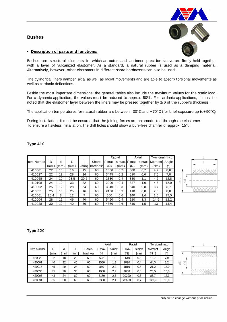
Bushes are structural elements, in which an outer and an inner precision sleeve are firmly held togetherwith a layer of vulcanized elastomer. As a standard, a natural rubber is used as a damping material.Alternatively, however, other elastomers in different shore hardnesses can also be used.
The cylindrical liners dampen axial as well as radial movements and are able to absorb torsional movements aswell as cardanic deflections.
Beside the most important dimensions, the general tables also include the maximum values for the static load.For a dynamic application, the values must be reduced to approx. 50%. For cardanic applications, it must benoted that the elastomer layer between the liners may be pressed together by 1/6 of the rubber’s thickness.
The application temperatures for natural rubber are between –30°C and +70°C (for brief exposure up to+90°C)
During installation, it must be ensured that the joining forces are not conducted through the elastomer.To ensure a flawless installation, the drill holes should show a burr-free chamfer of approx. 15°.
Type 410
Item Number D d L l Shore- F max. s max. F max. s max. Moment Angle(mm) (mm) (mm) (mm) hardness (N) (mm) (N) (mm) (Nm) (°)
410001 22 10 16 15 60 1580 0,2 300 0,7 4,2 8,8410027 22 12 28 24 60 3445 0,2 510 0,6 7,6 7,8410058 24 10 23,5 20,5 60 1830 0,4 380 1,1 4,9 12,8410108 24 10 33 22 60 2000 0,4 327 1,0 4,8 12,0410002 25 12 28 24 60 3340 0,3 540 0,8 8,7 8,7410051 25 13 25 16 60 2130 0,3 410 0,8 7,3 8,0410061 25,4 8 12 9 60 300 0,6 140 1,4 1,5 15,5410004 28 12 46 40 60 5450 0,4 910 1,3 14,5 12,2410028 30 12 40 36 60 4350 0,6 810 1,5 13 13,4
Radial Axial Torsional max:
Type 420
Item number D d L Shore- F max. s max. F max. s max. Moment Angle[mm] [mm] [mm] hardness [N] [mm] [N] [mm] [Nm] [°]
420029 32 18 20 60 622 1,0 2610 0,3 13,7 7,9420001 40 22 40 60 1580 1,3 9890 0,4 44,3 8,2420015 45 20 24 60 850 2,2 1910 0,8 21,2 13,0420033 45 20 30 60 1060 2,2 4650 0,8 26,5 13,0420003 48 24 80 60 3170 2,3 20290 0,8 88,7 12,3420031 55 30 66 60 3360 2,1 20650 0,7 120,9 10,0
Axial Radial Torsional max:
subject to change without prior notice
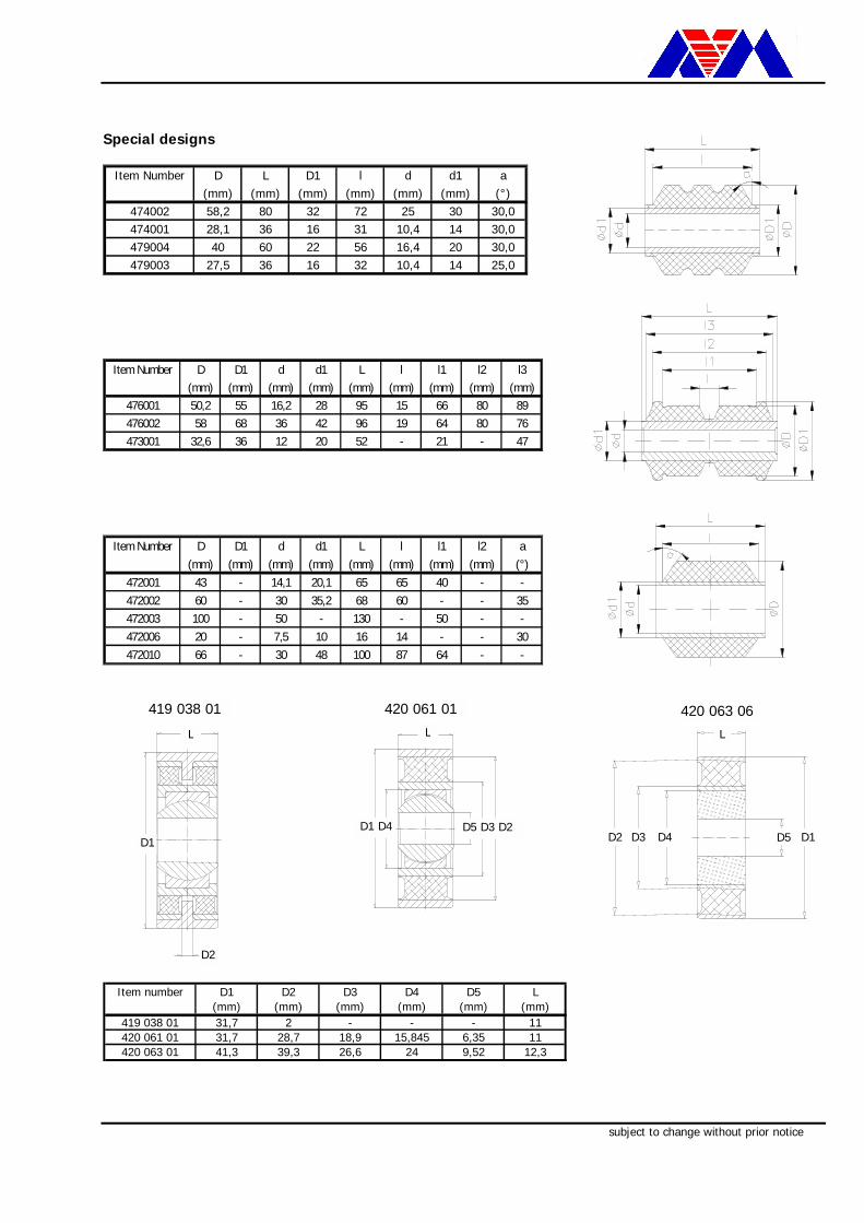
Special designs
Item Number D L D1 l d d1 a(mm) (mm) (mm) (mm) (mm) (mm) (°)
474002 58,2 80 32 72 25 30 30,0474001 28,1 36 16 31 10,4 14 30,0479004 40 60 22 56 16,4 20 30,0479003 27,5 36 16 32 10,4 14 25,0
Item Number D D1 d d1 L l l1 l2 l3(mm) (mm) (mm) (mm) (mm) (mm) (mm) (mm) (mm)
476001 50,2 55 16,2 28 95 15 66 80 89476002 58 68 36 42 96 19 64 80 76473001 32,6 36 12 20 52 - 21 - 47
Item Number D D1 d d1 L l l1 l2 a(mm) (mm) (mm) (mm) (mm) (mm) (mm) (mm) (°)
472001 43 - 14,1 20,1 65 65 40 - -472002 60 - 30 35,2 68 60 - - 35472003 100 - 50 - 130 - 50 - -472006 20 - 7,5 10 16 14 - - 30472010 66 - 30 48 100 87 64 - -
Item number D1 D2 D3 D4 D5 L(mm) (mm) (mm) (mm) (mm) (mm)
419 038 01 31,7 2 - - - 11420 061 01 31,7 28,7 18,9 15,845 6,35 11420 063 01 41,3 39,3 26,6 24 9,52 12,3
D1D2 D3 D4
L
D5
420 063 06L
D5 D3 D2 D1 D4
420 061 01
L
D2
D1
419 038 01
subject to change without prior notice
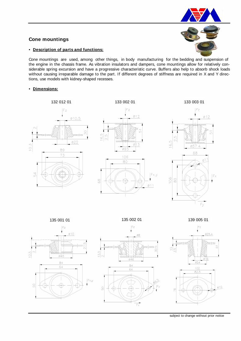
Cone Mounts
• Description of parts and functions:
Cone mountings are used, among other things, in body manufacturing for the bedding and suspension ofthe engine in the chassis frame. As vibration insulators and dampers, cone mountings allow for relatively con-siderable spring excursion and have a progressive characteristic curve. Buffers also help to absorb shock loadswithout causing irreparable damage to the part. If different degrees of stiffness are required in X and Y direc-tions, use models with kidney-shaped recesses.
• Dimensions:
133 003 01
135 001 01
132 012 01 133 002 01
139 005 01135 002 01


![ROSTA Anti-vibration Mounts - Transmissioner | Jens-S · ROSTA Anti- vibration Mounts ... Art. No. Type Natural frequency Gmni. – Gmax. [Hz] O P x max. Material structure (zinc-plated](https://img.pdfslide.us/doc/110x75/5c86c68009d3f29b298ce3e1/rosta-anti-vibration-mounts-transmissioner-jens-s-rosta-anti-vibration.jpg)