Embed Size (px)
Citation preview
International Journal of Advances in Electronics and Computer Science, ISSN: 2393-2835 Volume-4, Issue-1, Jan.-2017 http://iraj.in
Anti Theft Wheel Locking System With SMS Facility 6
ANTI THEFT WHEEL LOCKING SYSTEM WITH SMS FACILITY
1MAJOR S KIRAN, 2MAJOR ASHISH SIDHAWAT, 3MAJOR CS SHARMA
1,2,3MCEME, Secunderabad E-mail: [email protected]
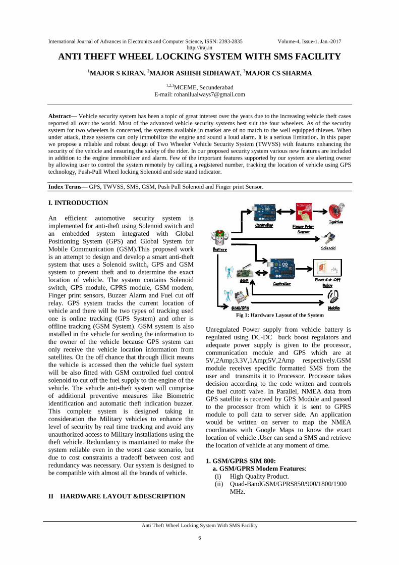
Abstract— Vehicle security system has been a topic of great interest over the years due to the increasing vehicle theft cases reported all over the world. Most of the advanced vehicle security systems best suit the four wheelers. As of the security system for two wheelers is concerned, the systems available in market are of no match to the well equipped thieves. When under attack, these systems can only immobilize the engine and sound a loud alarm. It is a serious limitation. In this paper we propose a reliable and robust design of Two Wheeler Vehicle Security System (TWVSS) with features enhancing the security of the vehicle and ensuring the safety of the rider. In our proposed security system various new features are included in addition to the engine immobilizer and alarm. Few of the important features supported by our system are alerting owner by allowing user to control the system remotely by calling a registered number, tracking the location of vehicle using GPS technology, Push-Pull Wheel locking Solenoid and side stand indicator. Index Terms— GPS, TWVSS, SMS, GSM, Push Pull Solenoid and Finger print Sensor. I. INTRODUCTION An efficient automotive security system is implemented for anti-theft using Solenoid switch and an embedded system integrated with Global Positioning System (GPS) and Global System for Mobile Communication (GSM).This proposed work is an attempt to design and develop a smart anti-theft system that uses a Solenoid switch, GPS and GSM system to prevent theft and to determine the exact location of vehicle. The system contains Solenoid switch, GPS module, GPRS module, GSM modem, Finger print sensors, Buzzer Alarm and Fuel cut off relay. GPS system tracks the current location of vehicle and there will be two types of tracking used one is online tracking (GPS System) and other is offline tracking (GSM System). GSM system is also installed in the vehicle for sending the information to the owner of the vehicle because GPS system can only receive the vehicle location information from satellites. On the off chance that through illicit means the vehicle is accessed then the vehicle fuel system will be also fitted with GSM controlled fuel control solenoid to cut off the fuel supply to the engine of the vehicle. The vehicle anti-theft system will comprise of additional preventive measures like Biometric identification and automatic theft indication buzzer. This complete system is designed taking in consideration the Military vehicles to enhance the level of security by real time tracking and avoid any unauthorized access to Military installations using the theft vehicle. Redundancy is maintained to make the system reliable even in the worst case scenario, but due to cost constraints a tradeoff between cost and redundancy was necessary. Our system is designed to be compatible with almost all the brands of vehicle. II HARDWARE LAYOUT &DESCRIPTION
Fig 1: Hardware Layout of the System
Unregulated Power supply from vehicle battery is regulated using DC-DC buck boost regulators and adequate power supply is given to the processor, communication module and GPS which are at 5V,2Amp;3.3V,1Amp;5V,2Amp respectively.GSM module receives specific formatted SMS from the user and transmits it to Processor. Processor takes decision according to the code written and controls the fuel cutoff valve. In Parallel, NMEA data from GPS satellite is received by GPS Module and passed to the processor from which it is sent to GPRS module to poll data to server side. An application would be written on server to map the NMEA coordinates with Google Maps to know the exact location of vehicle .User can send a SMS and retrieve the location of vehicle at any moment of time. 1. GSM/GPRS SIM 800: a. GSM/GPRS Modem Features:
(i) High Quality Product. (ii) Quad-BandGSM/GPRS850/900/1800/1900
MHz.
International Journal of Advances in Electronics and Computer Science, ISSN: 2393-2835 Volume-4, Issue-1, Jan.-2017 http://iraj.in
Anti Theft Wheel Locking System With SMS Facility 7
(iii) RS232 interface for direct communication with computer or MCU kit and USB Interface.
(iv) Configurable baud rate. (v) Wire Antenna (SMA connector with GSM
Antenna Optional). (vi) SIM Card holder. (vii) Built in Network Status LED. (viii) Inbuilt Powerful TCP/IP protocol stack for internet data transfer over GPRS. (ix) Normal operation temperature: -20 °C to +55 °C. (x) Input Voltage: 12V DC Max.
b. SIM 900A General Specification:
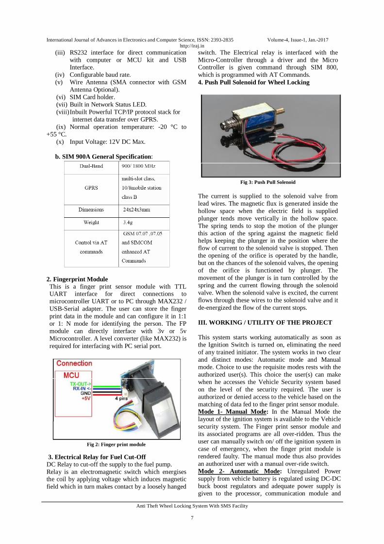
2. Fingerprint Module This is a finger print sensor module with TTL UART interface for direct connections to microcontroller UART or to PC through MAX232 / USB-Serial adapter. The user can store the finger print data in the module and can configure it in 1:1 or 1: N mode for identifying the person. The FP module can directly interface with 3v or 5v Microcontroller. A level converter (like MAX232) is required for interfacing with PC serial port.
Fig 2: Finger print module
3. Electrical Relay for Fuel Cut-Off DC Relay to cut-off the supply to the fuel pump. Relay is an electromagnetic switch which energises the coil by applying voltage which induces magnetic field which in turn makes contact by a loosely hanged
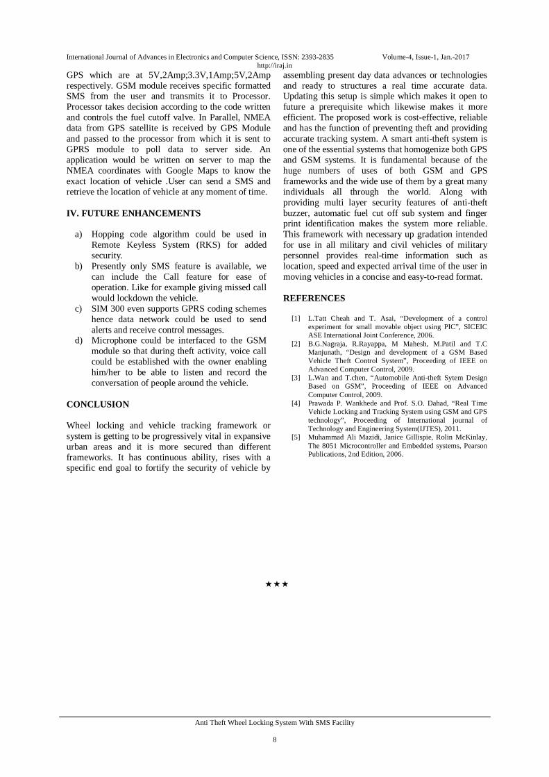
switch. The Electrical relay is interfaced with the Micro-Controller through a driver and the Micro Controller is given command through SIM 800, which is programmed with AT Commands. 4. Push Pull Solenoid for Wheel Locking
Fig 3: Push Pull Solenoid
The current is supplied to the solenoid valve from lead wires. The magnetic flux is generated inside the hollow space when the electric field is supplied plunger tends move vertically in the hollow space. The spring tends to stop the motion of the plunger this action of the spring against the magnetic field helps keeping the plunger in the position where the flow of current to the solenoid valve is stopped. Then the opening of the orifice is operated by the handle, but on the chances of the solenoid valves, the opening of the orifice is functioned by plunger. The movement of the plunger is in turn controlled by the spring and the current flowing through the solenoid valve. When the solenoid valve is excited, the current flows through these wires to the solenoid valve and it de-energized the flow of the current stops. III. WORKING / UTILITY OF THE PROJECT This system starts working automatically as soon as the Ignition Switch is turned on, eliminating the need of any trained initiator. The system works in two clear and distinct modes: Automatic mode and Manual mode. Choice to use the requisite modes rests with the authorized user(s). This choice the user(s) can make when he accesses the Vehicle Security system based on the level of the security required. The user is authorized or denied access to the vehicle based on the matching of data fed to the finger print sensor module. Mode 1- Manual Mode: In the Manual Mode the layout of the ignition system is available to the Vehicle security system. The Finger print sensor module and its associated programs are all over-ridden. Thus the user can manually switch on/ off the ignition system in case of emergency, when the finger print module is rendered faulty. The manual mode thus also provides an authorized user with a manual over-ride switch. Mode 2- Automatic Mode: Unregulated Power supply from vehicle battery is regulated using DC-DC buck boost regulators and adequate power supply is given to the processor, communication module and
International Journal of Advances in Electronics and Computer Science, ISSN: 2393-2835 Volume-4, Issue-1, Jan.-2017 http://iraj.in
Anti Theft Wheel Locking System With SMS Facility 8
GPS which are at 5V,2Amp;3.3V,1Amp;5V,2Amp respectively. GSM module receives specific formatted SMS from the user and transmits it to Processor. Processor takes decision according to the code written and controls the fuel cutoff valve. In Parallel, NMEA data from GPS satellite is received by GPS Module and passed to the processor from which it is sent to GPRS module to poll data to server side. An application would be written on server to map the NMEA coordinates with Google Maps to know the exact location of vehicle .User can send a SMS and retrieve the location of vehicle at any moment of time. IV. FUTURE ENHANCEMENTS
a) Hopping code algorithm could be used in Remote Keyless System (RKS) for added security.
b) Presently only SMS feature is available, we can include the Call feature for ease of operation. Like for example giving missed call would lockdown the vehicle.
c) SIM 300 even supports GPRS coding schemes hence data network could be used to send alerts and receive control messages.
d) Microphone could be interfaced to the GSM module so that during theft activity, voice call could be established with the owner enabling him/her to be able to listen and record the conversation of people around the vehicle.
CONCLUSION Wheel locking and vehicle tracking framework or system is getting to be progressively vital in expansive urban areas and it is more secured than different frameworks. It has continuous ability, rises with a specific end goal to fortify the security of vehicle by
assembling present day data advances or technologies and ready to structures a real time accurate data. Updating this setup is simple which makes it open to future a prerequisite which likewise makes it more efficient. The proposed work is cost-effective, reliable and has the function of preventing theft and providing accurate tracking system. A smart anti-theft system is one of the essential systems that homogenize both GPS and GSM systems. It is fundamental because of the huge numbers of uses of both GSM and GPS frameworks and the wide use of them by a great many individuals all through the world. Along with providing multi layer security features of anti-theft buzzer, automatic fuel cut off sub system and finger print identification makes the system more reliable. This framework with necessary up gradation intended for use in all military and civil vehicles of military personnel provides real-time information such as location, speed and expected arrival time of the user in moving vehicles in a concise and easy-to-read format. REFERENCES
[1] L.Tatt Cheah and T. Asai, “Development of a control experiment for small movable object using PIC”, SICEIC ASE International Joint Conference, 2006.
[2] B.G.Nagraja, R.Rayappa, M Mahesh, M.Patil and T.C Manjunath, “Design and development of a GSM Based Vehicle Theft Control System”, Proceeding of IEEE on Advanced Computer Control, 2009.
[3] L.Wan and T.chen, “Automobile Anti-theft Sytem Design Based on GSM”, Proceeding of IEEE on Advanced Computer Control, 2009.
[4] Prawada P. Wankhede and Prof. S.O. Dahad, “Real Time Vehicle Locking and Tracking System using GSM and GPS technology”, Proceeding of International journal of Technology and Engineering System(IJTES), 2011.
[5] Muhammad Ali Mazidi, Janice Gillispie, Rolin McKinlay, The 8051 Microcontroller and Embedded systems, Pearson Publications, 2nd Edition, 2006.