Embed Size (px)
Citation preview

1
ECE 445
Anti-lost/theft alarming system for personal belongings
Design Review
Project 24
Wenhao Li – Yunchi Sun – Xiying Wang
TA: Igor Fedorov
2
Table of Contents 1.0 INTRODUCTION...................................................................................................................3 1.1 Statement of Purpose.................................................................................................................3 1.2 Objectives............................................................................................................................. …3 2.0 DESIGN 2.1 Block Diagrams .....................................................................................................................4-5 2.2 Block Descriptions.................................................................................................................6-7
2.2.1 Keypad Module.......................................................................................................... 6 2.2.2 Controller Module.…................................................................................................. 6 2.2.3 Communication module……………………………………………………………..6 2.2.4 Power Module.............................................................................................................7 2.2.5 Display Module...........................................................................................................7
2.3 Schematics of Overall System...................................................................................................8 2.4 Simulations and Calculations...................................................................................................11 3.0 REQUIREMENTS AND VERIFICATION 3.1 Requirements Summary.....................................................................................................13-16 3.2 Tolerance Analysis..................................................................................................................17 4.0 COST AND SCHEDULE 4.1 Cost Analysis...........................................................................................................................18
4.1.1 Labor........................................................................................................................ 18 4.1.2 Parts..........................................................................................................................18 4.1.3 Grand Total ............................................................................................................. 19
4.2.0 Schedule...........................................................................................................................20-21 5.0 ETHICAL ISSUES................................................................................................................22 6.0 REFERENCES......................................................................................................................24 7.0 SAFETY ANALYSIS............................................................................................................25

3
1.0 Introduction 1.1 Statement of purpose Many precious personal belongings, either by theft or carelessness, are easily lost or cause serious damage. According to a report by TechCrunch: US citizens, on average, lost one smartphone annually, which caused 30 billion dollar loss of money in 2012. Not to mention the loss of wallet, which may cause the loss of your driving license, cash and credit cards. Our idea is to use wireless communication technology to remarkably decrease the loss rate of those important items you carry. Since those personal belongings (i.e. wallet, cell-phones, keychain) are supposed to be very close to you, we would pair them up(use transmitters and receiver) with a portable base device that could be easily hooked up/carried in your jacket/coats. This device will detect if any of the personal belongings are too far away from you (for example more than 2-5 meters) and send out an alarm indicating this item is under potential risk of loss. 1.2 Objectives 1.2.1 Goals The goal of our project is to design an effective alarming system that could prevent the potential loss of user's personal belongings. During an incidence the user should have a better chance to get back the losing item guided by the beep sound from the losing item. 1.2.2 Functions ● Pair up all the precious items to the main portable device ● Alert the user under an incidence when the item is out of certain range ● Trace back the potential lost item from the high-pitch alarming sound
1.2.3 Benefits and Features ● Bluetooth wireless communication system improves the accuracy of signal transmission ● Multi-paired up items function provides user information with one base device ● LCD display function easily indicates losing item ● Alarm function makes losing item traceable for users ● Manual on/off control for the base device and password protection ● Portable base device and tracking parts make users easy to carry around
4
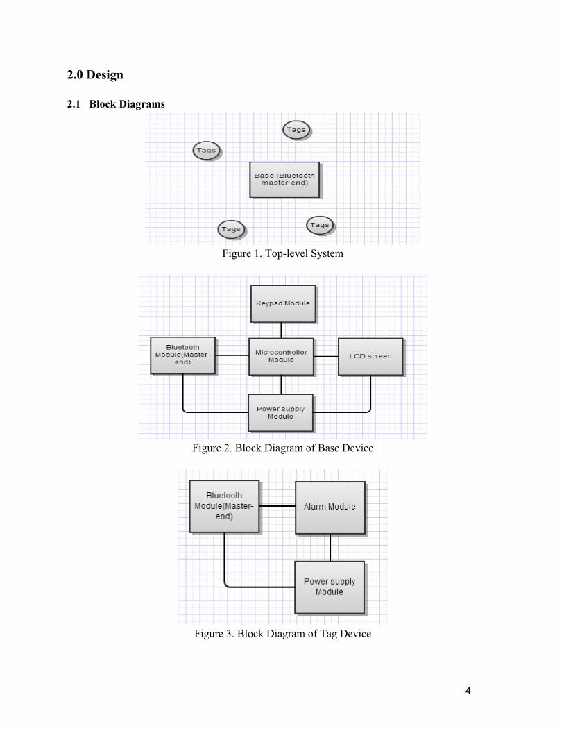
2.0 Design 2.1 Block Diagrams
Figure 1. Top-level System
Figure 2. Block Diagram of Base Device
Figure 3. Block Diagram of Tag Device
5
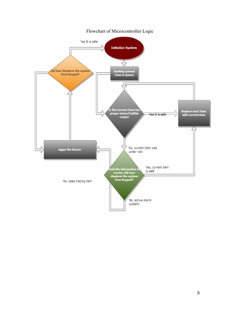
Flowchart of Microcontroller Logic
6
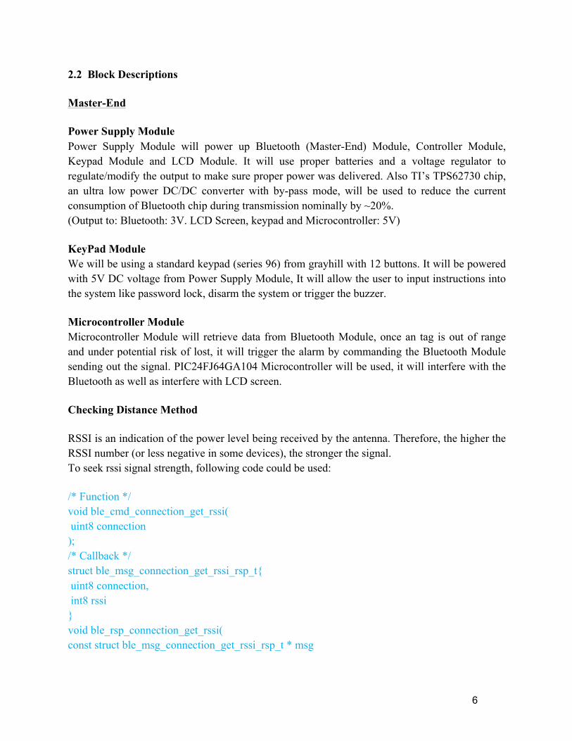
2.2 Block Descriptions Master-End Power Supply Module Power Supply Module will power up Bluetooth (Master-End) Module, Controller Module, Keypad Module and LCD Module. It will use proper batteries and a voltage regulator to regulate/modify the output to make sure proper power was delivered. Also TI’s TPS62730 chip, an ultra low power DC/DC converter with by-pass mode, will be used to reduce the current consumption of Bluetooth chip during transmission nominally by ~20%. (Output to: Bluetooth: 3V. LCD Screen, keypad and Microcontroller: 5V) KeyPad Module We will be using a standard keypad (series 96) from grayhill with 12 buttons. It will be powered with 5V DC voltage from Power Supply Module, It will allow the user to input instructions into the system like password lock, disarm the system or trigger the buzzer. Microcontroller Module Microcontroller Module will retrieve data from Bluetooth Module, once an tag is out of range and under potential risk of lost, it will trigger the alarm by commanding the Bluetooth Module sending out the signal. PIC24FJ64GA104 Microcontroller will be used, it will interfere with the Bluetooth as well as interfere with LCD screen. Checking Distance Method RSSI is an indication of the power level being received by the antenna. Therefore, the higher the RSSI number (or less negative in some devices), the stronger the signal. To seek rssi signal strength, following code could be used: /* Function */ void ble_cmd_connection_get_rssi( uint8 connection ); /* Callback */ struct ble_msg_connection_get_rssi_rsp_t{ uint8 connection, int8 rssi } void ble_rsp_connection_get_rssi( const struct ble_msg_connection_get_rssi_rsp_t * msg

7
After the Bluetooth Chip delivered, a detailed model of RSSI signal strength vs. Distance will be established. Certain range will be setup to trigger the alarm. Communication Module We are using the Bluegiga BLE112 chip as the Master End of the system. When in master mode, the chip could have up to 8 connections simultaneously. The Microcontroller can send a trigger signal and owner’s information through the Bluetooth Unit. Display Module LCD display is working under direction of the Micro-controller. It will display the information needed to users. The ACM1602A SERIES LCD screen was chosen. It will interfere with micro-controller via SPI and was powered by power supply module with 5V DC. Slave-End Power Supply Module Power Supply Module(Slave-End) will power up the Alarm Module to trigger the alarming buzzer. It will use CR2330 Lithium coin batteries, which outputs 3V voltage match the proper input of Alarm Module. It also supplies 3V to the Bluetooth (slave-end) using the same TPS62730 chip as the master-end. Communication Module We are also using the Bluegiga BLE112 chip which has the Bluetooth 4.0 (BLE) Single Mode Stack. The chip provides the Received Signal Strength Indication (RSSI) command to acquire the received signal strength. By comparing the RSSI values to a reference value can tell if the Slave End is within certain range from the Master End.
The chip also has its own CPU, when the RSSI from the Master End is below the reference value, it will send out a signal to trigger the alarm. And also it will communicate with the Master End to acquire the owner’s information to display on the LED screen. Alarm Module A FY14. 3-18Vdc mini-piezo beeper will be used which will emits a medium, high-pitched tone when energized. 13.8mm diameter x 7.5mm high. PC pins on 7.5mm centers. (Rated: 80 dB. 12Vdc, 7mA, 4Khz.) Figure. Parameter of the FY14 Buzzer
8
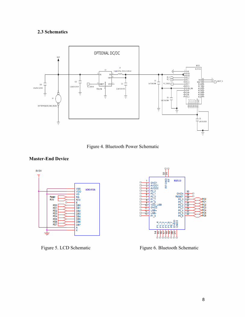
2.3 Schematics
Figure 4. Bluetooth Power Schematic
Master-End Device
Figure 5. LCD Schematic Figure 6. Bluetooth Schematic
9
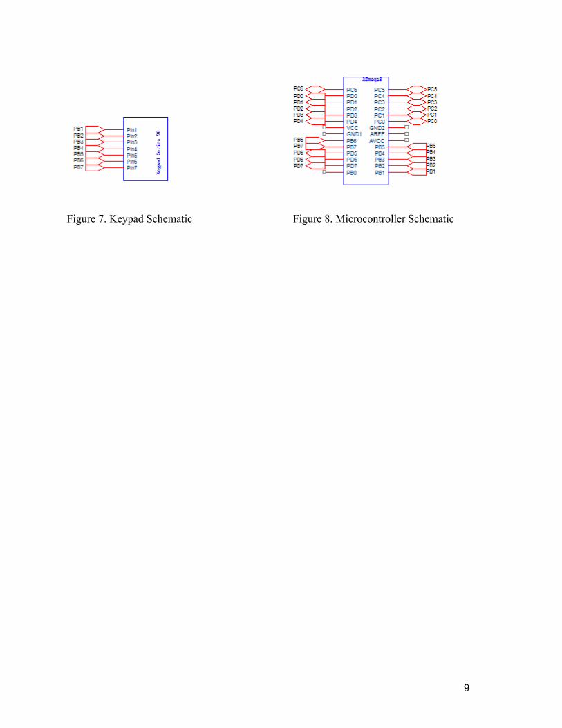
Figure 7. Keypad Schematic Figure 8. Microcontroller Schematic
10
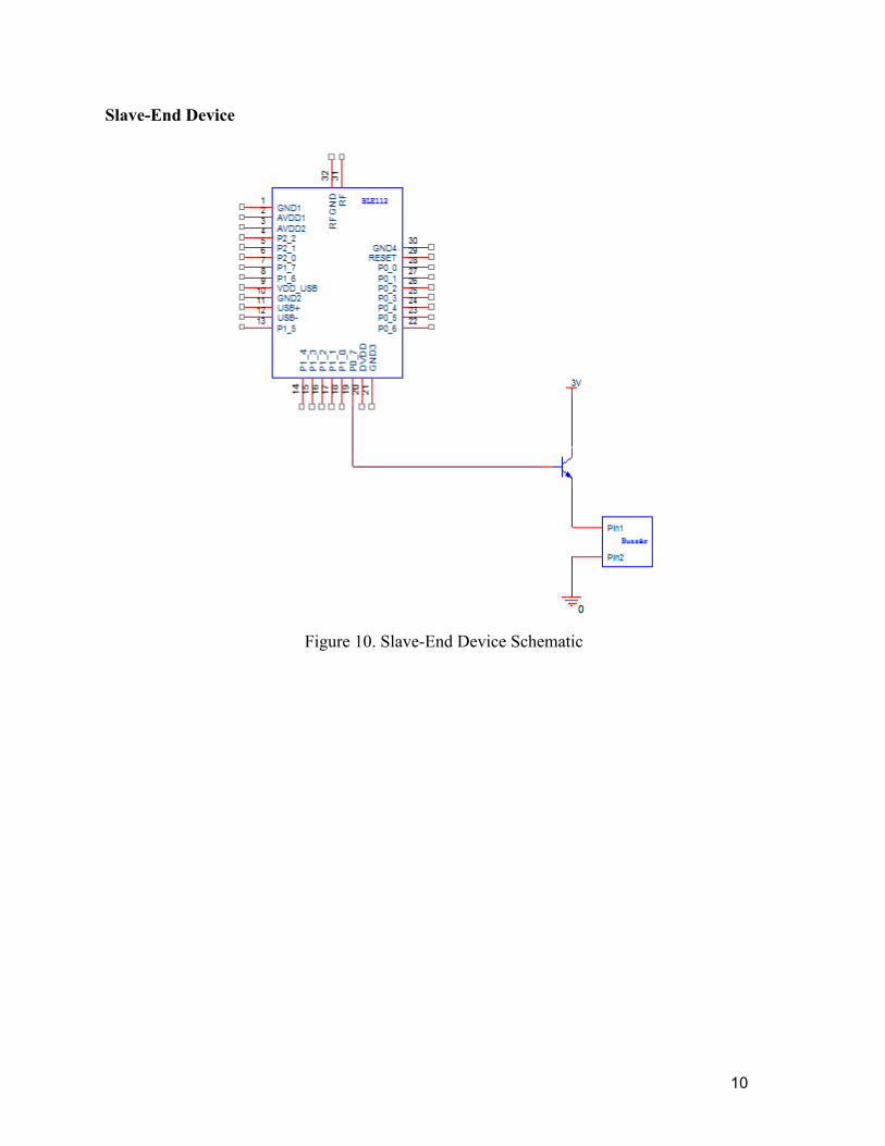
Slave-End Device
Figure 10. Slave-End Device Schematic
11
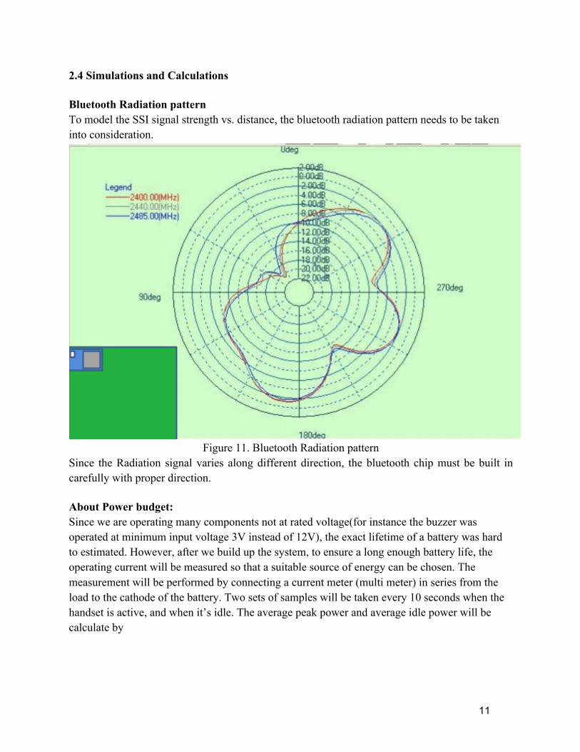
2.4 Simulations and Calculations Bluetooth Radiation pattern To model the SSI signal strength vs. distance, the bluetooth radiation pattern needs to be taken into consideration.
Figure 11. Bluetooth Radiation pattern
Since the Radiation signal varies along different direction, the bluetooth chip must be built in carefully with proper direction. About Power budget: Since we are operating many components not at rated voltage(for instance the buzzer was operated at minimum input voltage 3V instead of 12V), the exact lifetime of a battery was hard to estimated. However, after we build up the system, to ensure a long enough battery life, the operating current will be measured so that a suitable source of energy can be chosen. The measurement will be performed by connecting a current meter (multi meter) in series from the load to the cathode of the battery. Two sets of samples will be taken every 10 seconds when the handset is active, and when it’s idle. The average peak power and average idle power will be calculate by

12
At this point we could only gave a rough estimate of the battery life. For Slave end, we are using coin battery of 3V and 265mAH, the buzzer was about 0.1W while operating, which means the working hour of the buzzer is around 8 hours. Assuming on average the buzzer was working 5 min per day. The lifetime of each battery is about 8*60/5 = 96 days, which is about 3 month, a reasonable time for a battery. If we change the battery 4 times a year (slave end), the power budget (slave end) is roughly 4*(about 4 tags per system)*0.28 dollar/battery *4 battery/year = 15.72 dollar/year. For Master end, the transmitting power rating for Bluetooth chip is about 80 mW and idle power rating is about 1.2uW. We are going to set a proper transmitting frequency so that it would be fast enough for user to notice a potentially lost item while not wasting energy because of communicating too much. The Master end is much more complicated since there are so many components and the efficiency of voltage regulator was not estimated, actual data will be measured after the system was build-up. Furthermore, if the master end battery life is shorter than 1 month, we will consider using several 1.5V AAA batteries to compensate the current coin battery. The rough estimated power budget of master end would be around 50 dollar/year.
13
3.0 Requirements and Verification 3.1 Requirements & Verification
Master-End
Component Requirements Verification
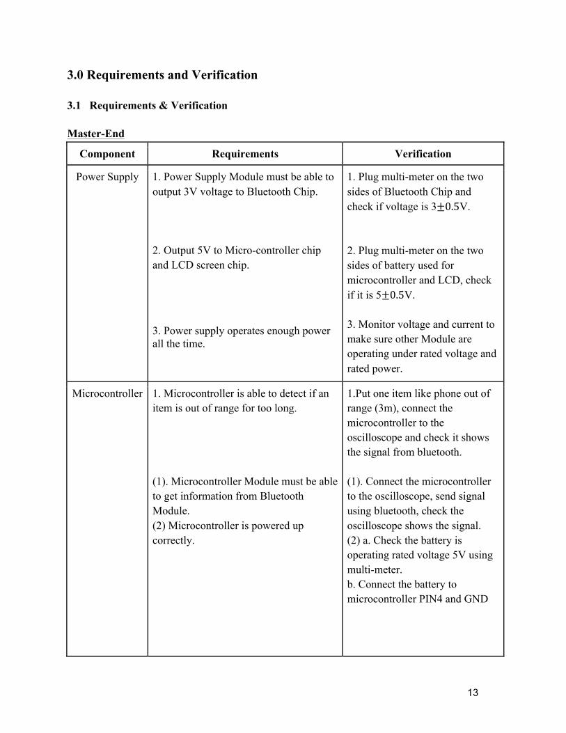
Power Supply 1. Power Supply Module must be able to output 3V voltage to Bluetooth Chip. 2. Output 5V to Micro-controller chip and LCD screen chip. 3. Power supply operates enough power all the time.
1. Plug multi-meter on the two sides of Bluetooth Chip and check if voltage is 3±0.5V. 2. Plug multi-meter on the two sides of battery used for microcontroller and LCD, check if it is 5±0.5V. 3. Monitor voltage and current to make sure other Module are operating under rated voltage and rated power.
Microcontroller 1. Microcontroller is able to detect if an item is out of range for too long. (1). Microcontroller Module must be able to get information from Bluetooth Module. (2) Microcontroller is powered up correctly.
1.Put one item like phone out of range (3m), connect the microcontroller to the oscilloscope and check it shows the signal from bluetooth. (1). Connect the microcontroller to the oscilloscope, send signal using bluetooth, check the oscilloscope shows the signal. (2) a. Check the battery is operating rated voltage 5V using multi-meter. b. Connect the battery to microcontroller PIN4 and GND
14
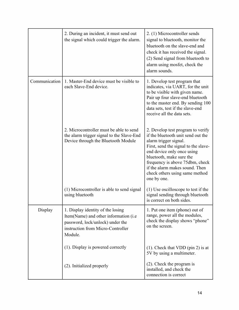
2. During an incident, it must send out the signal which could trigger the alarm.
2. (1) Microcontroller sends signal to bluetooth, monitor the bluetooth on the slave-end and check it has received the signal. (2) Send signal from bluetooth to alarm using mosfet, check the alarm sounds.
Communication 1. Master-End device must be visible to each Slave-End device. 2. Microcontroller must be able to send the alarm trigger signal to the Slave-End Device through the Bluetooth Module (1) Microcontroller is able to send signal using bluetooth
1. Develop test program that indicates, via UART, for the unit to be visible with given name. Pair up four slave-end bluetooth to the master end. By sending 100 data sets, test if the slave-end receive all the data sets. 2. Develop test program to verify if the bluetooth unit send out the alarm trigger signal. First, send the signal to the slave-end device only once using bluetooth, make sure the frequency is above 75dbm, check if the alarm makes sound. Then check others using same method one by one. (1) Use oscilloscope to test if the signal sending through bluetooth is correct on both sides.
Display 1. Display identity of the losing Item(Name) and other information (i.e password, lock/unlock) under the instruction from Micro-Controller Module. (1). Display is powered correctly (2). Initialized properly
1. Put one item (phone) out of range, power all the modules, check the display shows “phone” on the screen. (1). Check that VDD (pin 2) is at 5V by using a multimeter. (2). Check the program is installed, and check the connection is correct
15
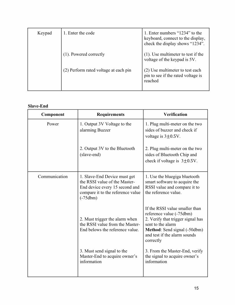
Keypad 1. Enter the code (1). Powered correctly (2) Perform rated voltage at each pin
1. Enter numbers “1234” to the keyboard, connect to the display, check the display shows “1234”. (1). Use multimeter to test if the voltage of the keypad is 5V. (2) Use multimeter to test each pin to see if the rated voltage is reached
Slave-End
Component Requirements Verification
Power 1. Output 3V Voltage to the alarming Buzzer 2. Output 3V to the Bluetooth (slave-end)
1. Plug multi-meter on the two sides of buzzer and check if voltage is 3±0.5V. 2. Plug multi-meter on the two sides of Bluetooth Chip and check if voltage is 3±0.5V.
Communication 1. Slave-End Device must get the RSSI value of the Master-End device every 15 second and compare it to the reference value (-75dbm) 2. Must trigger the alarm when the RSSI value from the Master-End belows the reference value. 3. Must send signal to the Master-End to acquire owner’s information
1. Use the bluegiga bluetooth smart software to acquire the RSSI value and compare it to the reference value. If the RSSI value smaller than reference value (-75dbm) 2. Verify that trigger signal has sent to the alarm Method: Send signal (-50dbm) and test if the alarm sounds correctly 3. From the Master-End, verify the signal to acquire owner’s information
16
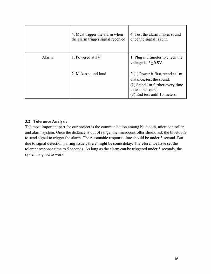
4. Must trigger the alarm when the alarm trigger signal received
4. Test the alarm makes sound once the signal is sent.
Alarm 1. Powered at 3V. 2. Makes sound loud
1. Plug multimeter to check the voltage is 3±0.5V. 2.(1) Power it first, stand at 1m distance, test the sound. (2) Stand 1m further every time to test the sound. (3) End test until 10 meters.
3.2 Tolerance Analysis The most important part for our project is the communication among bluetooth, microcontroller and alarm system. Once the distance is out of range, the microcontroller should ask the bluetooth to send signal to trigger the alarm. The reasonable response time should be under 3 second. But due to signal detection pairing issues, there might be some delay. Therefore, we have set the tolerant response time to 5 seconds. As long as the alarm can be triggered under 5 seconds, the system is good to work.
17
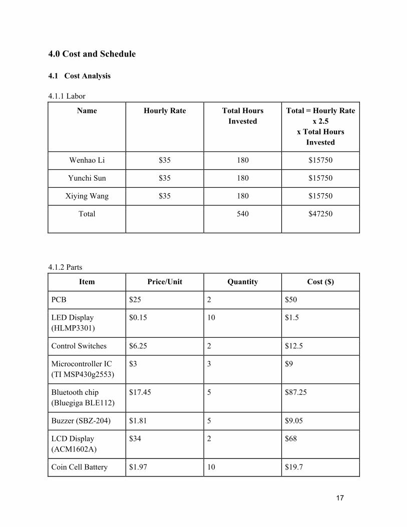
4.0 Cost and Schedule 4.1 Cost Analysis 4.1.1 Labor
Name Hourly Rate Total Hours Invested
Total = Hourly Rate x 2.5
x Total Hours Invested
Wenhao Li $35 180 $15750
Yunchi Sun $35 180 $15750
Xiying Wang $35 180 $15750
Total 540 $47250
4.1.2 Parts
Item Price/Unit Quantity Cost ($)
PCB $25 2 $50
LED Display (HLMP3301)
$0.15 10 $1.5
Control Switches $6.25 2 $12.5
Microcontroller IC (TI MSP430g2553)
$3 3 $9
Bluetooth chip (Bluegiga BLE112)
$17.45 5 $87.25
Buzzer (SBZ-204) $1.81 5 $9.05
LCD Display (ACM1602A)
$34 2 $68
Coin Cell Battery $1.97 10 $19.7

18
(DL2430)
Converter (TI TPS62730)
$2.02 5 10.1
Total $267.1
4.1.3 Grand Total
Section Total
Labor $47250
Parts $267.1
Total $47517.1
19
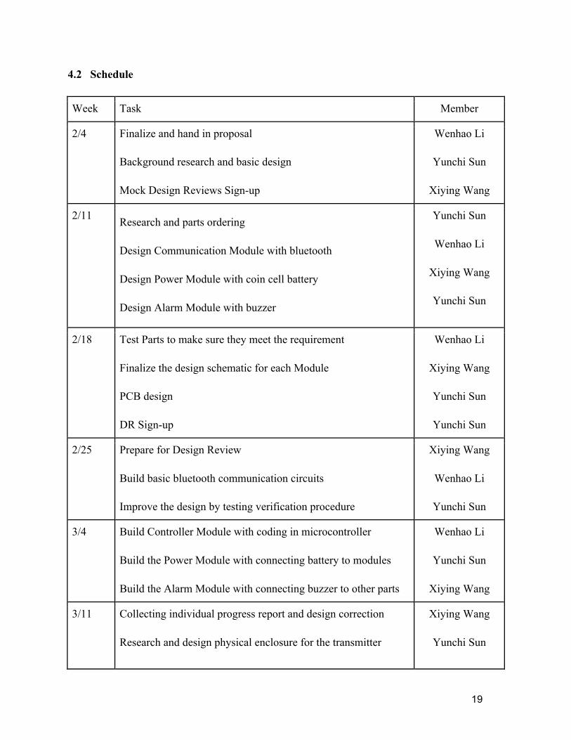
4.2 Schedule
Week Task Member
2/4 Finalize and hand in proposal Background research and basic design Mock Design Reviews Sign-up
Wenhao Li
Yunchi Sun
Xiying Wang
2/11 Research and parts ordering Design Communication Module with bluetooth Design Power Module with coin cell battery Design Alarm Module with buzzer
Yunchi Sun
Wenhao Li
Xiying Wang
Yunchi Sun
2/18 Test Parts to make sure they meet the requirement Finalize the design schematic for each Module PCB design DR Sign-up
Wenhao Li
Xiying Wang
Yunchi Sun
Yunchi Sun
2/25 Prepare for Design Review Build basic bluetooth communication circuits Improve the design by testing verification procedure
Xiying Wang
Wenhao Li
Yunchi Sun
3/4 Build Controller Module with coding in microcontroller Build the Power Module with connecting battery to modules Build the Alarm Module with connecting buzzer to other parts
Wenhao Li
Yunchi Sun
Xiying Wang
3/11 Collecting individual progress report and design correction Research and design physical enclosure for the transmitter
Xiying Wang
Yunchi Sun
20
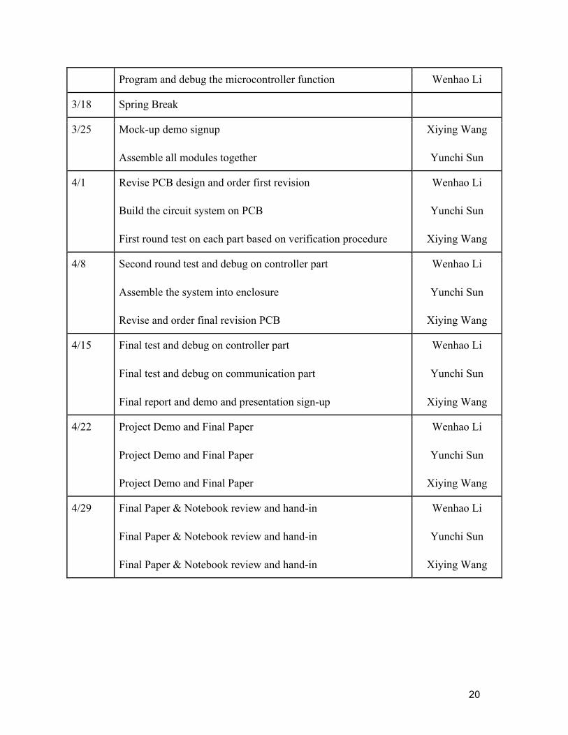
Program and debug the microcontroller function Wenhao Li
3/18 Spring Break
3/25 Mock-up demo signup Assemble all modules together
Xiying Wang
Yunchi Sun
4/1 Revise PCB design and order first revision Build the circuit system on PCB First round test on each part based on verification procedure
Wenhao Li
Yunchi Sun
Xiying Wang
4/8 Second round test and debug on controller part Assemble the system into enclosure Revise and order final revision PCB
Wenhao Li
Yunchi Sun
Xiying Wang
4/15 Final test and debug on controller part Final test and debug on communication part Final report and demo and presentation sign-up
Wenhao Li
Yunchi Sun
Xiying Wang
4/22 Project Demo and Final Paper Project Demo and Final Paper Project Demo and Final Paper
Wenhao Li
Yunchi Sun
Xiying Wang
4/29 Final Paper & Notebook review and hand-in Final Paper & Notebook review and hand-in Final Paper & Notebook review and hand-in
Wenhao Li
Yunchi Sun
Xiying Wang

21
5.0 Ethical Issues
The purpose of this project is to build a small tracking system for personal belongings in order to avoid treasure lost. Our project will be consistent with the IEEE Code of Ethics below. 1. to accept responsibility in making decisions consistent with the safety, health, and welfare of the public, and to disclose promptly factors that might endanger the public or the environment; The small part we are going to install on the item uses coin cell battery as power supply. We will make sure that the battery makes stable performance and be safe to users. Another part on the personal item is the buzzer. We will use the smallest and safest buzzer which makes loud sound but without any possible danger. 3. to be honest and realistic in stating claims or estimates based on available data; During the design process, we will make sure that all the calculation and verification are honest and real without any faking data. 5. to improve the understanding of technology; its appropriate application, and potential consequences; From this project, we have learned a lot about the bluetooth and wireless signal transceiving process. With further research on different models, we have seen the improvement of technology and its application and potential consequences. 6. to maintain and improve our technical competence and to undertake technological tasks for others only if qualified by training or experience, or after full disclosure of pertinent limitations; Without full qualification by training or experience, we will not apply our project to any market uses. 7. to seek, accept, and offer honest criticism of technical work, to acknowledge and correct errors, and to credit properly the contributions of others; Our group will accept all constructive and useful suggestion and criticism from others towards our project in order to improve it to the best. We will also acknowledge anyone who has great contribution to this project. 9. to avoid injuring others, their property, reputation, or employment by false or malicious action;

22
We will make sure that the product we have developed will offer users accurate data, and will not provide any false information which may cause users injury or damage of their property. 10. to assist colleagues and co-workers in their professional development and to support them in following this code of ethics. All group members will strictly follow the code of ethics during this project. We will assist each other on developing the product because we are completely responsible for our project and users safety concerns.
23
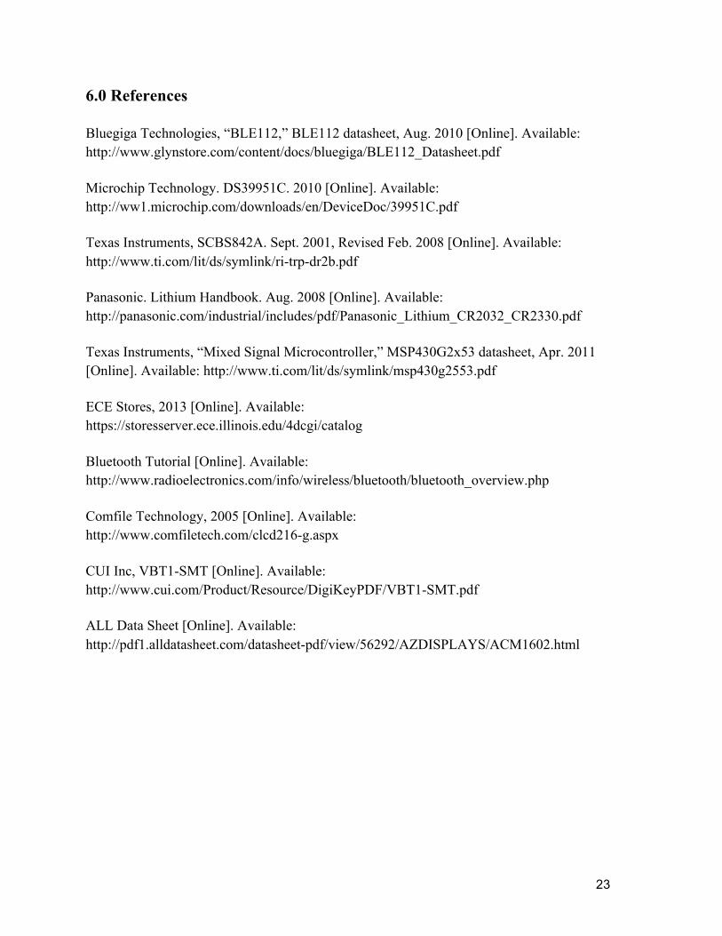
6.0 References Bluegiga Technologies, “BLE112,” BLE112 datasheet, Aug. 2010 [Online]. Available: http://www.glynstore.com/content/docs/bluegiga/BLE112_Datasheet.pdf Microchip Technology. DS39951C. 2010 [Online]. Available: http://ww1.microchip.com/downloads/en/DeviceDoc/39951C.pdf Texas Instruments, SCBS842A. Sept. 2001, Revised Feb. 2008 [Online]. Available: http://www.ti.com/lit/ds/symlink/ri-trp-dr2b.pdf Panasonic. Lithium Handbook. Aug. 2008 [Online]. Available: http://panasonic.com/industrial/includes/pdf/Panasonic_Lithium_CR2032_CR2330.pdf Texas Instruments, “Mixed Signal Microcontroller,” MSP430G2x53 datasheet, Apr. 2011 [Online]. Available: http://www.ti.com/lit/ds/symlink/msp430g2553.pdf ECE Stores, 2013 [Online]. Available: https://storesserver.ece.illinois.edu/4dcgi/catalog Bluetooth Tutorial [Online]. Available: http://www.radioelectronics.com/info/wireless/bluetooth/bluetooth_overview.php Comfile Technology, 2005 [Online]. Available: http://www.comfiletech.com/clcd216-g.aspx CUI Inc, VBT1-SMT [Online]. Available: http://www.cui.com/Product/Resource/DigiKeyPDF/VBT1-SMT.pdf ALL Data Sheet [Online]. Available: http://pdf1.alldatasheet.com/datasheet-pdf/view/56292/AZDISPLAYS/ACM1602.html

24
7.0 Safety Analysis For our project, safety is the most important factor because the product is designed for personal uses. We will make sure that all the components of our product has highly stable performance as parts will not get too hot for close use and so on. Also during the design, team members will be cautious with any type of potential danger due to soldering, hand-making parts and circuit connection. Another big factor for this project is alarming system, which requires buzzer beams loud at certain distance. We will make sure that the buzzer we use has no hearing damage even at its closest distance. Also we will ensure that the buzzer will not make sounds unless required distance is reached. Therefore, the product we make will be completely safe from any potential hearing damage.