Embed Size (px)
Citation preview
NWS EHB 6-513
FP-6-5/(FP-6-6 blank)
Figure FO6-2. Antenna Fault IsolationFlowchart (Sheet 1 of 13)
A1
Note:
This flowchart provides a fundamental order in which various Antenna Alarms and faults should be resolved. Most alarms have basic troubleshooting in Alarm Table 6-2 (Ped Alarms). Many antenna problems have multiple alarms associated with them, often alarms that appear unassociated with the primary cause. Several antenna problems do not have associated alarms; those symptoms are noted where appropriate.
Investigate DC Power ProblemsSPIP +28V Power Supply Fail (253)SPIP +5V Power Supply Fail (255)
Elevation Housing PS Fail (565)Azimuth Housing PS Fail (566)
Power Amplifier150V PS
AZ or EL Servo Amp
Servo MotorAZ or EL checkout the same
Azimuth Motor Overtemp (320)Elevation Motor Overtemp (305)
MechanicalNoises/Vibrations
Pedestal Sensors
Elevation Gearbox Oil Level Low (314)Azimuth Gearbox Oil Level Low (325)
Bull Gear Oil Level Low (326)Pedestal Safe Switch Open (337)
EncoderAzimuth Encoder Light Failure (324)Elevation Encoder Light Failure (313)
SoftwarePedestal Unable To Park (339)
RCP AZ Control Unresponsive (357)RCP EL Control Unresponsive (358)RCP In Control Shutdown State (356)
Cut Transition Timeout (698)
Azimuth Amplifier Inhibit (315)Elevation Amplifier Inhibit (300)
Azimuth Stow Pin Engaged (321)Azimuth Handwheel Engaged (329) Elevation Stow Pin Engaged (306)
Elevation Handwheel Engaged (328)Elevation in – Dead Limit (261)Elevation In + Dead Limit (262)
AZ or EL Power Amp Alarms
Azimuth Amplifier Current Limit (316)Azimuth Amplifier Overtemp (317)
Azimuth Amp Power Supply Fail (334)Elevation Amplifier Current Limit (301)
Elevation Amplifier Overtemp (302)Elevation Amp Power Supply Fail (335)
Perform SPIP Power Verification Fault Note 29,
steps 1-6
Power Amplifier 150V PS
Pedestal +150V UnderVoltage (304)Pedestal +150V OverVoltage (303)
Fault Note 38, AZ/EL Drive Motor Check
Determine if problem is azimuth or elevation. If there
are no other alarms, go to STS and drive antenna in each axis to find problem
axis.
Fault Note 38, AZ/EL Drive Motor Check
If there are no apparent motor or gearing problems, run Fault Note 37, Pedestal
Performance Check/Calibration and see if
problem clears. If problem persists, call the WSR-88D
Hotline.
Pedestal Sensors Flow Charts A6 and A7
Encoder Flow Chart A12
Go to Pedestal Software Flow Chart A13
Inhibit Alarm Flow Charts A2 (AZ) and A3 (EL)
Fault Note 33, Power Amplifier 150V Power Supply Check
AZ/EL Servo Amplifier Flow Charts A4 (AZ) and A5 (EL)
Antenna Troubleshooting Order Of Precedence
Troubleshoot power supply problems first. Next, proceed to the appropriate column for the specific alarm/problem. Note the chain for Power Amp, Servo Motor, and mechanical troubles. This is the main progression for the most serious antenna problems. Many of these alarms interact; meaning for example, that a Power Amplifier alarm can be caused by a servo motor or mechanical problem. Troubleshoot the system, not just an alarm.
For general antenna problems, the azimuth and elevation assemblies are troubleshot the same. The only difference is the addition of slip rings when troubleshooting elevation problems.
NWS EHB 6-513
FP-6-7/(FP-6-8 blank)
Figure FO6-2. Antenna Fault IsolationFlowchart (Sheet 2 of 13)
A2
Areassociated
alarms present –Az Stow Pin (321) or
Az Handwheel (329)
?
NO
NOTES:
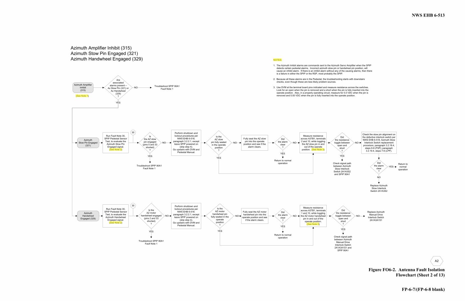
1. The Azimuth Inhibit alarms are commands sent to the Azimuth Servo Amplifier when the SPIP detects certain pedestal alarms. Incorrect azimuth stow pin or handwheel pin position, will cause an inhibit alarm. If there is an inhibit alarm without any of the causing alarms, then thereis a failure in either the SPIP or the RSP, most probably the SPIP.
2. Because all these alarms are in the Pedestal, the troubleshooting starts with downstairs checks, even though these are less likely problem sources.
3. Use DVM at the terminal board pins indicated and measure resistance across the switches.Look for an open when the pin is removed and a short when the pin is fully inserted into the operate position. Also, in a properly operating circuit, measure for 5.0 VDC when the pin is removed and 0.00 VDC when the pin is fully inserted into the operate position.
Azimuth Amplifier Inhibit (315)Azimuth Stow Pin Engaged (321)Azimuth Handwheel Engaged (329)
Run Fault Note 30, SPIP Pedestal Sensor Test, to evaluate the
Azimuth Stow Pin Engaged signal.
(See Note 2)
Perform shutdown and lockout procedures per
NWS EHB 6-518, paragraph 3.2.2.1, except leave SPIP powered on
(skip step 4). Go upstairs with DVM and
Pedestal Manual.
Didthe alarm
clear?
YES
NO
YES
30
Isthe AZ stow pin engaged
(pins 5 and 33shorted)
?
Troubleshoot SPIP 90A1 Fault Note 1
YES
NO
Fully seat the AZ stow pin into the operate
position and see if the alarm clears.
Return to normal operation Check signal path
between Azimuth Stow Interlock
Switch 2A1A3S2 and SPIP 90A1
Didthe resistance toggle between
open andshort
?
YES
NOAzimuth
Stow Pin Engaged (321)
Troubleshoot SPIP 90A1Fault Note 1
Measure resistance across A3TB1, terminals 2 and 10, while toggling the AZ stow pin in and
out of the operate position. (See Note 3)
Is theAZ stow
pin fully seated in the operate
position?
NO
YES
Check the stow pin alignment on the defective interlock switch per NWS EHB 6-518, Azimuth Stow
Interlock Switch replacement procedure, paragraph 3.2.18.4,
steps 6-8 (FSP); paragraph 3.2.19.4, steps 7-9 (LPP).
Didthe alarm
clear?
NO
Return to normal
operationYES
Run Fault Note 30, SPIP Pedestal Sensor Test, to evaluate the Azimuth Handwheel
Engaged signal.(See Note 2)
Didthe alarm
clear?
YES
NO
30
Is the AZ motor
handwheel engaged(pins 2 and 33
shorted)?
Troubleshoot SPIP 90A1 Fault Note 1
YES
NO
Fully seat the AZ motor handwheel pin into the
operate position and see if the alarm clears.
Return to normal operation Check signal path
between Azimuth Manual Drive
Interlock Switch 2A1A3A1S1 and
SPIP 90A1
YES
NOAzimuth
Handwheel Engaged (329)
Measure resistance across A3TB1, terminals 1 and 10, while toggling the AZ motor handwheel
pin in and out of the operate position.
(See Note 3)
Is theAZ motor
handwheel pinfully seated in the
operate position
?
NO
YES
Replace Azimuth Manual Drive
Interlock Switch 2A1A3A1S1
Perform shutdown and lockout procedures per
NWS EHB 6-518, paragraph 3.2.2.1, except leave SPIP powered on
(skip step 4). Go upstairs with DVM and
Pedestal Manual.
Replace Azimuth Stow Interlock
Switch 2A1A3S2
Azimuth Amplifier Inhibit (315)
(See Note 1)
Didthe resistance toggle between
open andshort
?
NWS EHB 6-513
FP-6-9/(FP-6-10 blank)
Figure FO6-2. Antenna Fault IsolationFlowchart (Sheet 3 of 13)
A3
Areassociated alarms
present –EL Stow Pin (306), EL
Handwheel (328), Elevation -Dead Limit (261), or
Elevation + DeadLimit (262)
?
NO
NOTES:
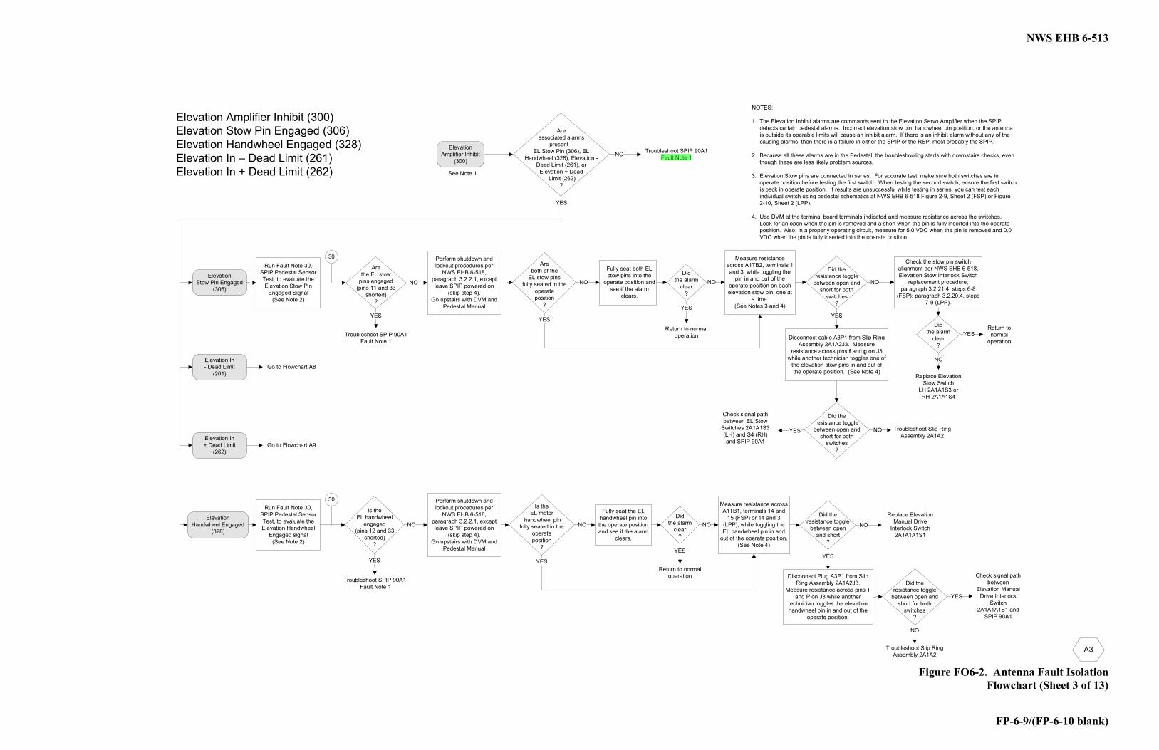
1. The Elevation Inhibit alarms are commands sent to the Elevation Servo Amplifier when the SPIP detects certain pedestal alarms. Incorrect elevation stow pin, handwheel pin position, or the antenna is outside its operable limits will cause an inhibit alarm. If there is an inhibit alarm without any of the causing alarms, then there is a failure in either the SPIP or the RSP, most probably the SPIP.
2. Because all these alarms are in the Pedestal, the troubleshooting starts with downstairs checks, even though these are less likely problem sources.
3. Elevation Stow pins are connected in series. For accurate test, make sure both switches are in operate position before testing the first switch. When testing the second switch, ensure the first switch is back in operate position. If results are unsuccessful while testing in series, you can test each individual switch using pedestal schematics at NWS EHB 6-518 Figure 2-9, Sheet 2 (FSP) or Figure 2-10, Sheet 2 (LPP).
4. Use DVM at the terminal board terminals indicated and measure resistance across the switches.Look for an open when the pin is removed and a short when the pin is fully inserted into the operate position. Also, in a properly operating circuit, measure for 5.0 VDC when the pin is removed and 0.0 VDC when the pin is fully inserted into the operate position.
Elevation Amplifier Inhibit (300)Elevation Stow Pin Engaged (306)Elevation Handwheel Engaged (328)Elevation In – Dead Limit (261)Elevation In + Dead Limit (262)
Run Fault Note 30, SPIP Pedestal Sensor Test, to evaluate the Elevation Stow Pin
Engaged Signal(See Note 2)
Didthe alarm
clear?
YES
NO
YES
30
Arethe EL stow
pins engaged(pins 11 and 33
shorted)?
Troubleshoot SPIP 90A1Fault Note 1
YES
NO
Fully seat both EL stow pins into the
operate position and see if the alarm
clears.
Return to normal operation
Check signal path between EL Stow
Switches 2A1A1S3 (LH) and S4 (RH) and SPIP 90A1
Did theresistance toggle
between open and short for both
switches?
YES
NOElevation
Stow Pin Engaged (306)
Troubleshoot SPIP 90A1Fault Note 1
Measure resistance across A1TB2, terminals 1 and 3, while toggling the
pin in and out of the operate position on each elevation stow pin, one at
a time. (See Notes 3 and 4)
Are both of the
EL stow pinsfully seated in the
operate position
?
NO
YES
Check the stow pin switch alignment per NWS EHB 6-518, Elevation Stow Interlock Switch
replacement procedure, paragraph 3.2.21.4, steps 6-8
(FSP); paragraph 3.2.20.4, steps 7-9 (LPP).
Didthe alarm
clear?
NO
Return to normal
operationYES
Run Fault Note 30, SPIP Pedestal Sensor Test, to evaluate the Elevation Handwheel
Engaged signal(See Note 2)
Didthe alarm
clear?
YES
NO
30
Is theEL handwheel
engaged(pins 12 and 33
shorted)?
Troubleshoot SPIP 90A1Fault Note 1
YES
NO
Fully seat the EL handwheel pin into the operate position and see if the alarm
clears.
Return to normal operation Check signal path
between Elevation Manual
Drive Interlock Switch
2A1A1A1S1 and SPIP 90A1
Did theresistance toggle
between open and short
?
YES
NOElevation
Handwheel Engaged(328)
Measure resistance across A1TB1, terminals 14 and
15 (FSP) or 14 and 3 (LPP), while toggling the EL handwheel pin in and
out of the operate position. (See Note 4)
Is theEL motor
handwheel pinfully seated in the
operate position
?
NO
YES
Replace Elevation Manual Drive
Interlock Switch 2A1A1A1S1
Perform shutdown and lockout procedures per
NWS EHB 6-518, paragraph 3.2.2.1, except leave SPIP powered on
(skip step 4). Go upstairs with DVM and
Pedestal Manual
Perform shutdown and lockout procedures per
NWS EHB 6-518, paragraph 3.2.2.1, except leave SPIP powered on
(skip step 4). Go upstairs with DVM and
Pedestal Manual
Replace Elevation Stow Switch
LH 2A1A1S3 or RH 2A1A1S4
Elevation Amplifier Inhibit
(300)
Disconnect cable A3P1 from Slip Ring Assembly 2A1A2J3. Measure
resistance across pins f and g on J3 while another technician toggles one of
the elevation stow pins in and out of the operate position. (See Note 4)
Did theresistance toggle
between open and short for both
switches?
YES Troubleshoot Slip Ring Assembly 2A1A2
NO
Disconnect Plug A3P1 from Slip Ring Assembly 2A1A2J3.
Measure resistance across pins T and P on J3 while another
technician toggles the elevation handwheel pin in and out of the
operate position.
Did theresistance toggle
between open and short for both
switches?
Troubleshoot Slip Ring Assembly 2A1A2
NO
YES
Elevation In+ Dead Limit
(262)
Elevation In- Dead Limit
(261)
Go to Flowchart A9
Go to Flowchart A8
See Note 1
NWS EHB 6-513
FP-6-19/(FP-6-20 blank)
Figure FO6-2. Antenna Fault IsolationFlowchart (Sheet 8 of 13)
A8
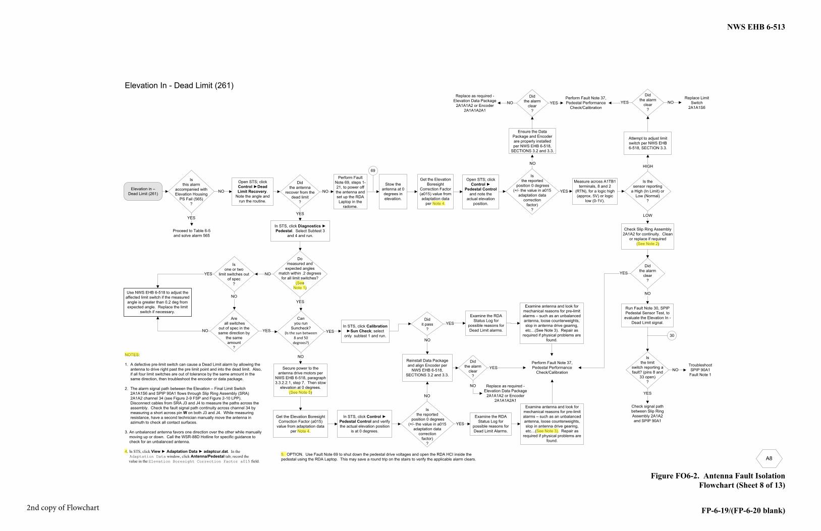
Elevation In - Dead Limit (261)
Open STS; click Control Dead Limit Recovery.
Note the angle and run the routine.
Didthe antenna
recover from the dead limit
?
YES
NO NO
NOTES:
1. A defective pre-limit switch can cause a Dead Limit alarm by allowing theantenna to drive right past the pre limit point and into the dead limit. Also,if all four limit switches are out of tolerance by the same amount in thesame direction, then troubleshoot the encoder or data package.
2. The alarm signal path between the Elevation – Final Limit Switch2A1A1S6 and SPIP 90A1 flows through Slip Ring Assembly (SRA)2A1A2 channel 34 (see Figure 2-9 FSP and Figure 2-10 LPP).Disconnect cables from SRA J3 and J4 to measure the paths across theassembly. Check the fault signal path continuity across channel 34 bymeasuring a short across pin W on both J3 and J4. While measuringresistance, have a second technician manually move the antenna inazimuth to check all contact surfaces.
3. An unbalanced antenna favors one direction over the other while manuallymoving up or down. Call the WSR-88D Hotline for specific guidance tocheck for an unbalanced antenna.
4. In STS, click View Adaptation Data adaptcur.dat. In the Adaptation Data window, click Antenna/Pedestal tab; record the value in the Elevation Boresight Correction Factor a015 field.
Did it pass
?
In STS, click Diagnostics Pedestal. Select Subtest 3
and 4 and run.
Perform Fault Note 37, Pedestal Performance
Check/Calibration
YESIn STS, click Calibration
Sun Check; selectonly subtest 1 and run.
Secure power to the antenna drive motors per
NWS EHB 6-518, paragraph 3.3.2.2.1, step 7. Then stow
elevation at 0 degrees. (See Note 5)
NO
Can you run
Suncheck? (Is the sun between
8 and 50 degrees?)
YES
In STS, click Control Pedestal Control and verify the actual elevation position
is at 0 degrees.
Isthe reported
position 0 degrees (+/- the value in a015
adaptation data correction
factor) ?
YES
Reinstall Data Package and align Encoder per
NWS EHB 6-518, SECTIONS 3.2 and 3.3.
NO
NO
Isthis alarm
accompanied with Elevation Housing
PS Fail (565)?
Proceed to Table 6-5 and solve alarm 565
YES
Perform Fault Note 69, steps 1-21, to power off the antenna and set up the RDA Laptop in the
radome.
Replace Limit Switch
2A1A1S6
Check signal path between Slip Ring Assembly 2A1A2 and SPIP 90A1
Measure across A1TB1 terminals, 8 and 2
(RTN), for a logic high (approx. 5V) or logic
low (0-1V).
Is thesensor reporting
a High (In Limit) or Low (Normal)
?
HIGH
LOW
Perform Fault Note 37, Pedestal Performance
Check/Calibration
Attempt to adjust limit switch per NWS EHB 6-518, SECTION 3.3.
Check Slip Ring Assembly 2A1A2 for continuity. Clean
or replace if required(See Note 2)
Did the alarm
clear?
NOYES
Data Package and
NWS EHB 6-518, SECTIONS 3.2 and 3.3.
Did the alarm
clear?
YESNO
Did the alarm
clear?
YES
NO
Replace as required -Elevation Data Package
2A1A1A2 or Encoder 2A1A1A2A1
Did the alarm
clear?
YES
NO
Replace as required -Elevation Data Package
2A1A1A2 or Encoder 2A1A1A2A1
Domeasured and
expected anglesmatch within .2 degrees
for all limit switches?(See
Note 1)
YES
Troubleshoot SPIP 90A1
Fault Note 1
Use NWS EHB 6-518 to adjust the affected limit switch if the measured angle is greater than 0.2 deg from expected angle. Replace the limit
switch if necessary.
YES
Stow the antenna at 0 degrees in elevation.
Open STS; click Control
Pedestal Controland note the
actual elevation position.
Run Fault Note 30, SPIP Pedestal Sensor Test, to
evaluate the Elevation In -Dead Limit signal.
Isthe limit
switch reporting a fault? (pins 8 and
33 open)?
YES
NO
30
Isthe reported
position 0 degrees (+/- the value in a015
adaptation data correction
factor) ?
NO
69
Elevation in –Dead Limit (261)
Isone or two
limit switches out of spec
?
NO
Areall switches
out of spec in the same direction by
the same amount
?
NO
YES
YES
NO
Examine the RDA Status Log for
possible reasons for Dead Limit alarms.
Examine the RDA Status Log for
possible reasons for Dead Limit Alarms.
Examine antenna and look for mechanical reasons for pre-limit alarms – such as an unbalanced antenna, loose counterweights, slop in antenna drive gearing, etc…(See Note 3). Repair as
required if physical problems are found.
Examine antenna and look for mechanical reasons for pre-limit alarms – such as an unbalanced antenna, loose counterweights, slop in antenna drive gearing, etc…(See Note 3). Repair as
required if physical problems are found.
Get the Elevation Boresight
Correction Factor (a015) value from adaptation data
per Note 4.
5. OPTION. Use Fault Note 69 to shut down the pedestal drive voltages and open the RDA HCI inside thepedestal using the RDA Laptop. This may save a round trip on the stairs to verify the applicable alarm clears.
Get the Elevation Boresight Correction Factor (a015)
value from adaptation data per Note 4.
2nd copy of Flowchart
NWS EHB 6-513
6-121/(6-122 blank)
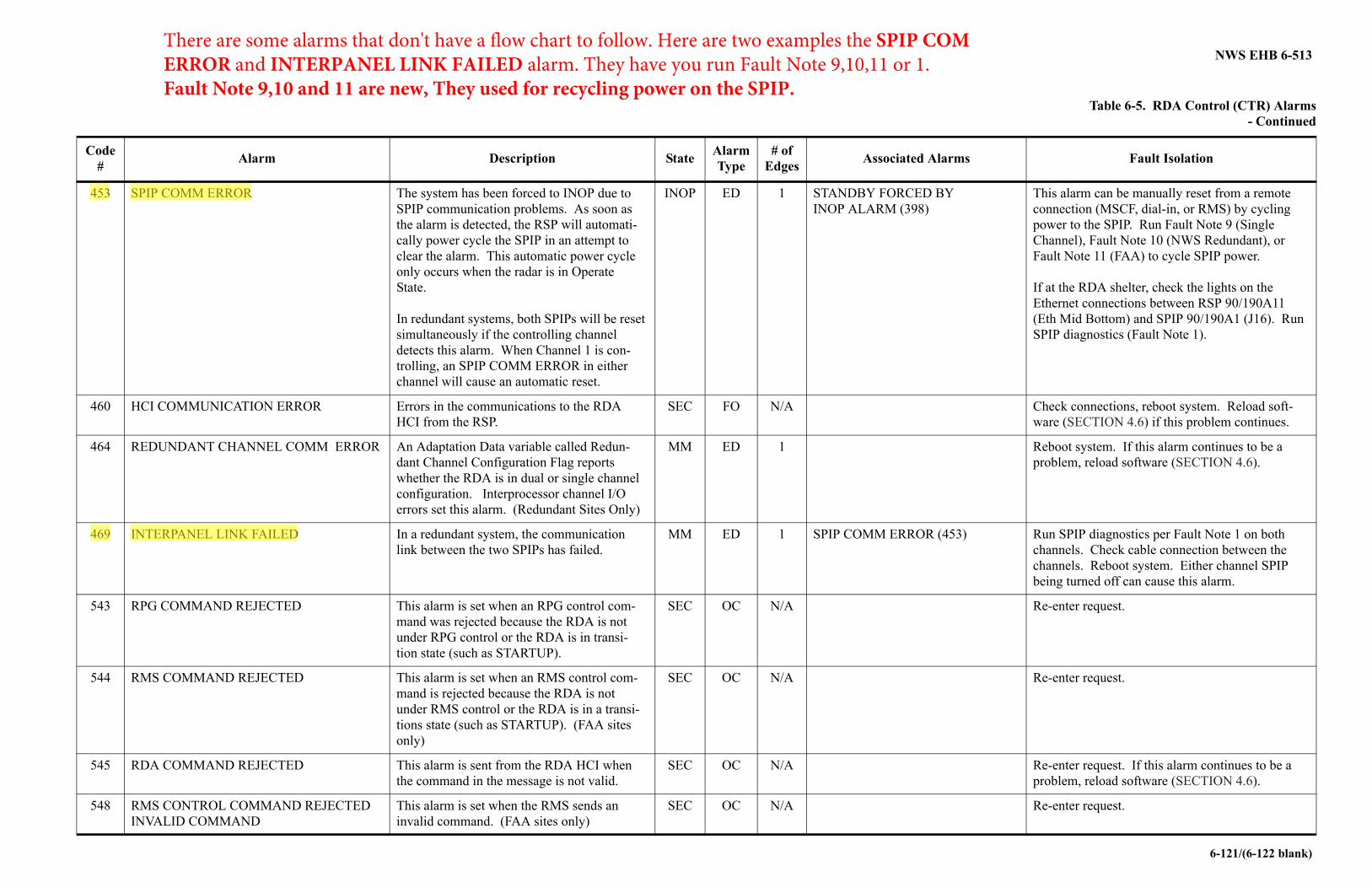
Table 6-5. RDA Control (CTR) Alarms - Continued
Code #
Alarm Description StateAlarmType
# of Edges
Associated Alarms Fault Isolation
453 SPIP COMM ERROR The system has been forced to INOP due to SPIP communication problems. As soon as the alarm is detected, the RSP will automati-cally power cycle the SPIP in an attempt to clear the alarm. This automatic power cycle only occurs when the radar is in Operate State.
In redundant systems, both SPIPs will be reset simultaneously if the controlling channel detects this alarm. When Channel 1 is con-trolling, an SPIP COMM ERROR in either channel will cause an automatic reset.
INOP ED 1 STANDBY FORCED BY INOP ALARM (398)
This alarm can be manually reset from a remote connection (MSCF, dial-in, or RMS) by cycling power to the SPIP. Run Fault Note 9 (Single Channel), Fault Note 10 (NWS Redundant), or Fault Note 11 (FAA) to cycle SPIP power.
If at the RDA shelter, check the lights on the Ethernet connections between RSP 90/190A11 (Eth Mid Bottom) and SPIP 90/190A1 (J16). Run SPIP diagnostics (Fault Note 1).
460 HCI COMMUNICATION ERROR Errors in the communications to the RDA HCI from the RSP.
SEC FO N/A Check connections, reboot system. Reload soft-ware (SECTION 4.6) if this problem continues.
464 REDUNDANT CHANNEL COMM ERROR An Adaptation Data variable called Redun-dant Channel Configuration Flag reports whether the RDA is in dual or single channel configuration. Interprocessor channel I/O errors set this alarm. (Redundant Sites Only)
MM ED 1 Reboot system. If this alarm continues to be a problem, reload software (SECTION 4.6).
469 INTERPANEL LINK FAILED In a redundant system, the communication link between the two SPIPs has failed.
MM ED 1 SPIP COMM ERROR (453) Run SPIP diagnostics per Fault Note 1 on both channels. Check cable connection between the channels. Reboot system. Either channel SPIP being turned off can cause this alarm.
543 RPG COMMAND REJECTED This alarm is set when an RPG control com-mand was rejected because the RDA is not under RPG control or the RDA is in transi-tion state (such as STARTUP).
SEC OC N/A Re-enter request.
544 RMS COMMAND REJECTED This alarm is set when an RMS control com-mand is rejected because the RDA is not under RMS control or the RDA is in a transi-tions state (such as STARTUP). (FAA sites only)
SEC OC N/A Re-enter request.
545 RDA COMMAND REJECTED This alarm is sent from the RDA HCI when the command in the message is not valid.
SEC OC N/A Re-enter request. If this alarm continues to be a problem, reload software (SECTION 4.6).
548 RMS CONTROL COMMAND REJECTED INVALID COMMAND
This alarm is set when the RMS sends an invalid command. (FAA sites only)
SEC OC N/A Re-enter request.
There are some alarms that don't have a flow chart to follow. Here are two examples the SPIP COM ERROR and INTERPANEL LINK FAILED alarm. They have you run Fault Note 9,10,11 or 1. Fault Note 9,10 and 11 are new, They used for recycling power on the SPIP.
NWS EHB 6-513
6-482
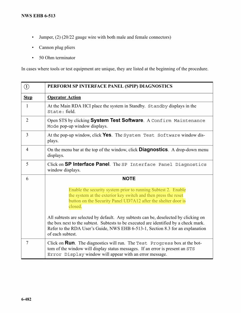
• Jumper, (2) (20/22 gauge wire with both male and female connectors)
• Cannon plug pliers
• 50 Ohm terminator
In cases where tools or test equipment are unique, they are listed at the beginning of the procedure.
PERFORM SP INTERFACE PANEL (SPIP) DIAGNOSTICS
Step Operator Action
1 At the Main RDA HCI place the system in Standby. Standby displays in the State: field.
2 Open STS by clicking System Test Software. A Confirm MaintenanceMode pop-up window displays.
3 At the pop-up window, click Yes. The System Test Software window dis-plays.
4 On the menu bar at the top of the window, click Diagnostics. A drop-down menu displays.
5 Click on SP Interface Panel. The SP Interface Panel Diagnostics window displays.
6 NOTE
Enable the security system prior to running Subtest 2. Enable the system at the exterior key switch and then press the reset button on the Security Panel UD7A12 after the shelter door is closed.
All subtests are selected by default. Any subtests can be, deselected by clicking on the box next to the subtest. Subtests to be executed are identified by a check mark. Refer to the RDA User’s Guide, NWS EHB 6-513-1, Section 8.3 for an explanation of each subtest.
7 Click on Run. The diagnostics will run. The Test Progress box at the bot-tom of the window will display status messages. If an error is present an STS Error Display window will appear with an error message.
NWS EHB 6-513
6-483
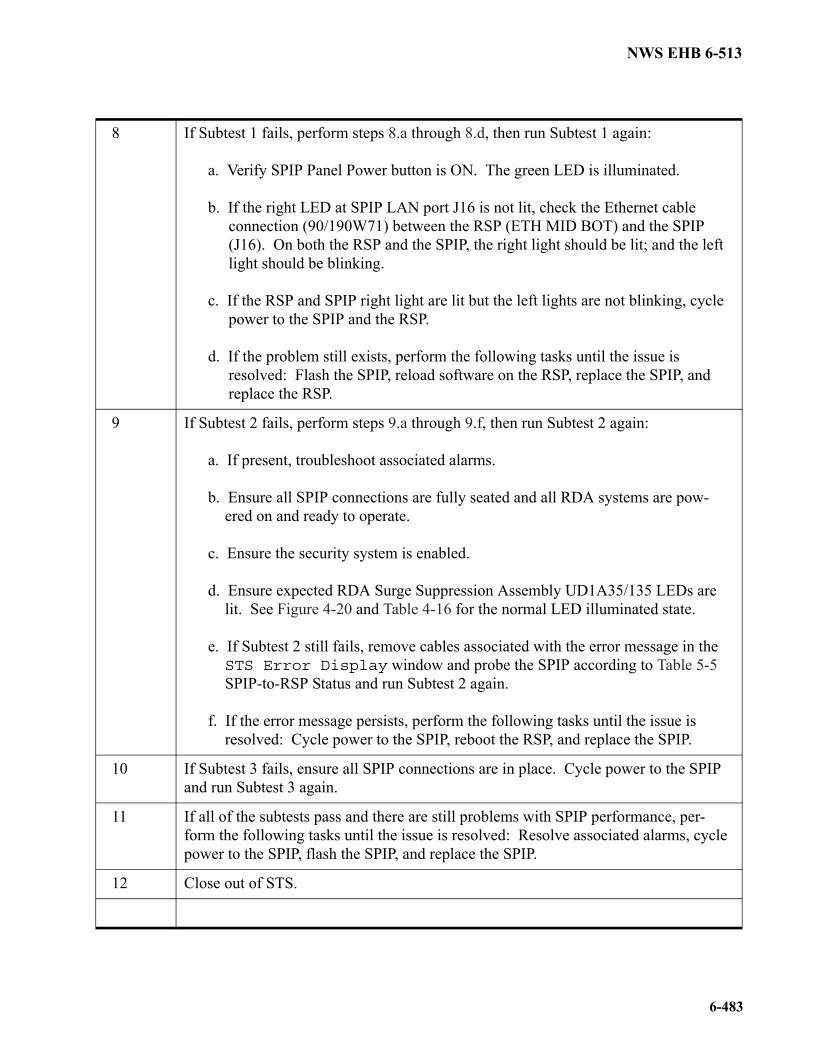
8 If Subtest 1 fails, perform steps 8.a through 8.d, then run Subtest 1 again:
a. Verify SPIP Panel Power button is ON. The green LED is illuminated.
b. If the right LED at SPIP LAN port J16 is not lit, check the Ethernet cableconnection (90/190W71) between the RSP (ETH MID BOT) and the SPIP(J16). On both the RSP and the SPIP, the right light should be lit; and the leftlight should be blinking.
c. If the RSP and SPIP right light are lit but the left lights are not blinking, cyclepower to the SPIP and the RSP.
d. If the problem still exists, perform the following tasks until the issue isresolved: Flash the SPIP, reload software on the RSP, replace the SPIP, andreplace the RSP.
9 If Subtest 2 fails, perform steps 9.a through 9.f, then run Subtest 2 again:
a. If present, troubleshoot associated alarms.
b. Ensure all SPIP connections are fully seated and all RDA systems are pow-ered on and ready to operate.
c. Ensure the security system is enabled.
d. Ensure expected RDA Surge Suppression Assembly UD1A35/135 LEDs arelit. See Figure 4-20 and Table 4-16 for the normal LED illuminated state.
e. If Subtest 2 still fails, remove cables associated with the error message in theSTS Error Display window and probe the SPIP according to Table 5-5SPIP-to-RSP Status and run Subtest 2 again.
f. If the error message persists, perform the following tasks until the issue isresolved: Cycle power to the SPIP, reboot the RSP, and replace the SPIP.
10 If Subtest 3 fails, ensure all SPIP connections are in place. Cycle power to the SPIP and run Subtest 3 again.
11 If all of the subtests pass and there are still problems with SPIP performance, per-form the following tasks until the issue is resolved: Resolve associated alarms, cycle power to the SPIP, flash the SPIP, and replace the SPIP.
12 Close out of STS.
NWS EHB 6-513
6-488
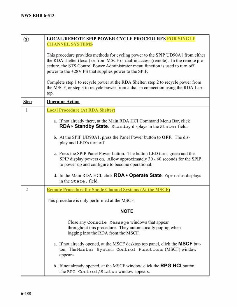
LOCAL/REMOTE SPIP POWER CYCLE PROCEDURES FOR SINGLE CHANNEL SYSTEMS
This procedure provides methods for cycling power to the SPIP UD90A1 from either the RDA shelter (local) or from MSCF or dial-in access (remote). In the remote pro-cedure, the STS Control Power Administrator menu function is used to turn off power to the +28V PS that supplies power to the SPIP.
Complete step 1 to recycle power at the RDA Shelter, step 2 to recycle power from the MSCF, or step 3 to recycle power from a dial-in connection using the RDA Lap-top.
Step Operator Action
1 Local Procedure (At RDA Shelter)
a. If not already there, at the Main RDA HCI Command Menu Bar, clickRDA Standby State. Standby displays in the State: field.
b. At the SPIP UD90A1, press the Panel Power button to OFF. The dis- play and LED’s turn off.
c. Press the SPIP Panel Power button. The button LED turns green and theSPIP display powers on. Allow approximately 30 - 60 seconds for the SPIPto power up and configure to become operational.
d. In the Main RDA HCI, click RDA Operate State. Operate displaysin the State: field.
2 Remote Procedure for Single Channel Systems (At the MSCF)
This procedure is only performed at the MSCF.
NOTE
Close any Console Message windows that appear throughout this procedure. They automatically pop-up when logging into the RDA from the MSCF.
a. If not already opened, at the MSCF desktop top panel, click the MSCF but-ton. The Master System Control Functions (MSCF) windowappears.
b. If not already opened, at the MSCF window, click the RPG HCI button.The RPG Control/Status window appears.
NWS EHB 6-513
6-489
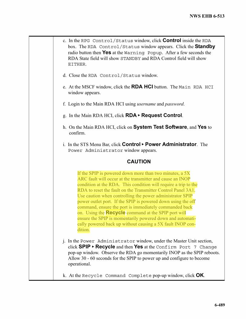
c. In the RPG Control/Status window, click Control inside the RDAbox. The RDA Control/Status window appears. Click the Standbyradio button then Yes at the Warning Popup. After a few seconds theRDA State field will show STANDBY and RDA Control field will showEITHER.
d. Close the RDA Control/Status window.
e. At the MSCF window, click the RDA HCI button. The Main RDA HCIwindow appears.
f. Login to the Main RDA HCI using username and password.
g. In the Main RDA HCI, click RDA Request Control.
h. On the Main RDA HCI, click on System Test Software, and Yes toconfirm.
i. In the STS Menu Bar, click Control Power Administrator. ThePower Administrator window appears.
CAUTION
If the SPIP is powered down more than two minutes, a 5X ARC fault will occur at the transmitter and cause an INOP condition at the RDA. This condition will require a trip to the RDA to reset the fault on the Transmitter Control Panel 3A1. Use caution when controlling the power administrator SPIP power outlet port. If the SPIP is powered down using the off command, ensure the port is immediately commanded back on. Using the Recycle command at the SPIP port will ensure the SPIP is momentarily powered down and automati-cally powered back up without causing a 5X fault INOP con-dition.
j. In the Power Administrator window, under the Master Unit section,click SPIP Recycle and then Yes at the Confirm Port 7 Changepop-up window. Observe the RDA go momentarily INOP as the SPIP reboots.Allow 30 - 60 seconds for the SPIP to power up and configure to becomeoperational.
k. At the Recycle Command Complete pop-up window, click OK.
NWS EHB 6-513
6-490
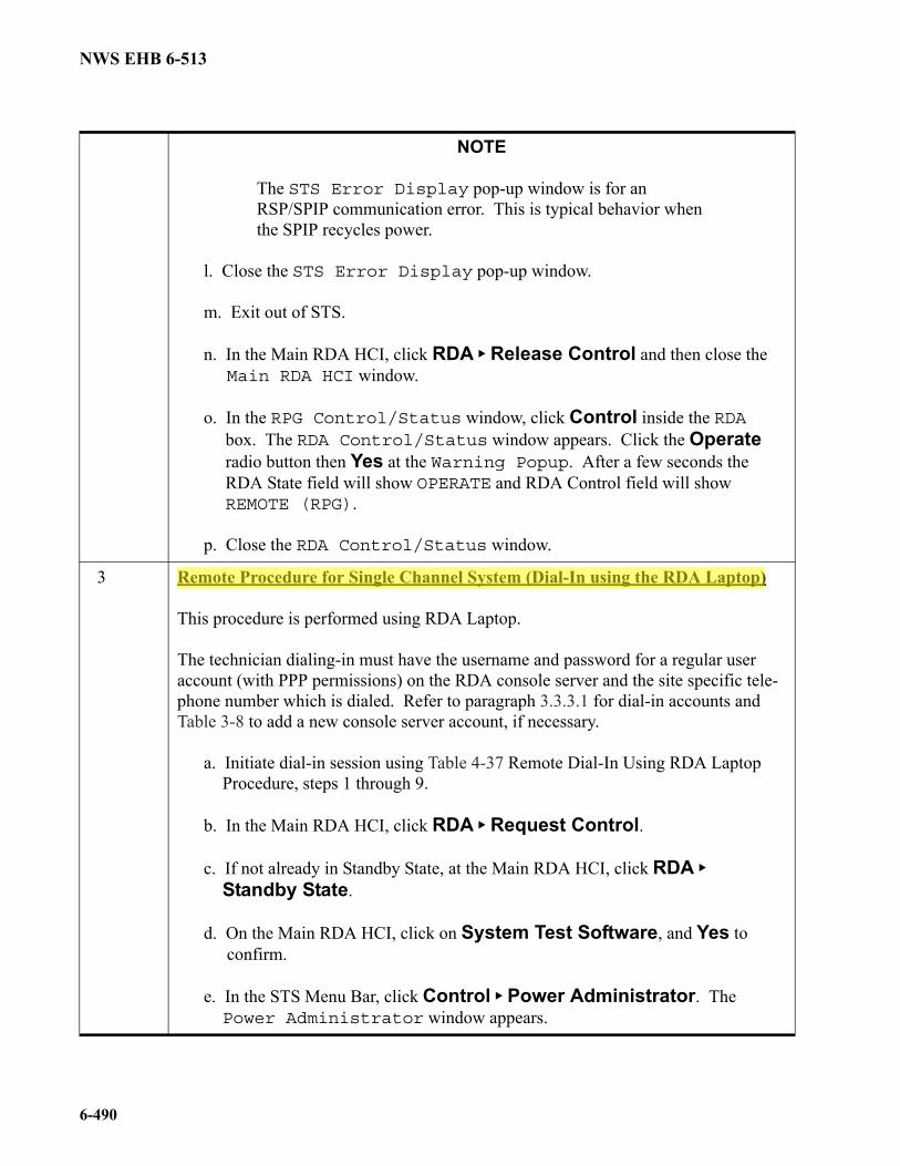
NOTE
The STS Error Display pop-up window is for an RSP/SPIP communication error. This is typical behavior when the SPIP recycles power.
l. Close the STS Error Display pop-up window.
m. Exit out of STS.
n. In the Main RDA HCI, click RDA Release Control and then close theMain RDA HCI window.
o. In the RPG Control/Status window, click Control inside the RDAbox. The RDA Control/Status window appears. Click the Operateradio button then Yes at the Warning Popup. After a few seconds theRDA State field will show OPERATE and RDA Control field will showREMOTE (RPG).
p. Close the RDA Control/Status window.
3 Remote Procedure for Single Channel System (Dial-In using the RDA Laptop)
This procedure is performed using RDA Laptop.
The technician dialing-in must have the username and password for a regular user account (with PPP permissions) on the RDA console server and the site specific tele-phone number which is dialed. Refer to paragraph 3.3.3.1 for dial-in accounts and Table 3-8 to add a new console server account, if necessary.
a. Initiate dial-in session using Table 4-37 Remote Dial-In Using RDA LaptopProcedure, steps 1 through 9.
b. In the Main RDA HCI, click RDA Request Control.
c. If not already in Standby State, at the Main RDA HCI, click RDA
Standby State.
d. On the Main RDA HCI, click on System Test Software, and Yes toconfirm.
e. In the STS Menu Bar, click Control Power Administrator. ThePower Administrator window appears.
NWS EHB 6-513
6-491
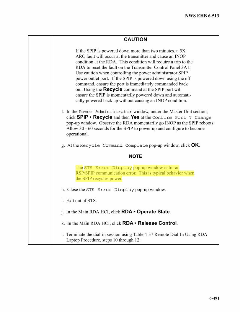
CAUTION
If the SPIP is powered down more than two minutes, a 5X ARC fault will occur at the transmitter and cause an INOP condition at the RDA. This condition will require a trip to the RDA to reset the fault on the Transmitter Control Panel 3A1. Use caution when controlling the power administrator SPIP power outlet port. If the SPIP is powered down using the off command, ensure the port is immediately commanded back on. Using the Recycle command at the SPIP port will ensure the SPIP is momentarily powered down and automati-cally powered back up without causing an INOP condition.
f. In the Power Administrator window, under the Master Unit section,click SPIP Recycle and then Yes at the Confirm Port 7 Changepop-up window. Observe the RDA momentarily go INOP as the SPIP reboots.Allow 30 - 60 seconds for the SPIP to power up and configure to becomeoperational.
g. At the Recycle Command Complete pop-up window, click OK.
NOTE
The STS Error Display pop-up window is for an RSP/SPIP communication error. This is typical behavior when the SPIP recycles power.
h. Close the STS Error Display pop-up window.
i. Exit out of STS.
j. In the Main RDA HCI, click RDA Operate State.
k. In the Main RDA HCI, click RDA Release Control.
l. Terminate the dial-in session using Table 4-37 Remote Dial-In Using RDALaptop Procedure, steps 10 through 12.
NWS EHB 6-513
6-492
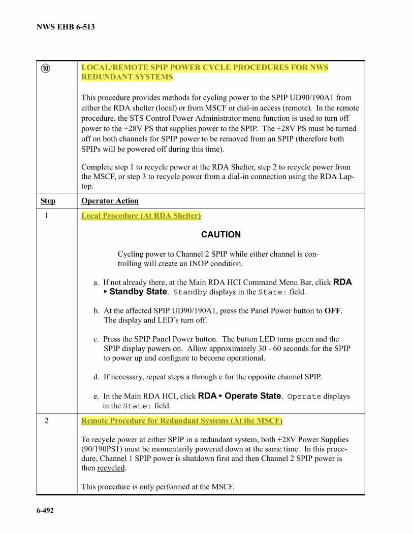
LOCAL/REMOTE SPIP POWER CYCLE PROCEDURES FOR NWS REDUNDANT SYSTEMS
This procedure provides methods for cycling power to the SPIP UD90/190A1 from either the RDA shelter (local) or from MSCF or dial-in access (remote). In the remote procedure, the STS Control Power Administrator menu function is used to turn off power to the +28V PS that supplies power to the SPIP. The +28V PS must be turned off on both channels for SPIP power to be removed from an SPIP (therefore both SPIPs will be powered off during this time).
Complete step 1 to recycle power at the RDA Shelter, step 2 to recycle power from the MSCF, or step 3 to recycle power from a dial-in connection using the RDA Lap-top.
Step Operator Action
1 Local Procedure (At RDA Shelter)
CAUTION
Cycling power to Channel 2 SPIP while either channel is con-trolling will create an INOP condition.
a. If not already there, at the Main RDA HCI Command Menu Bar, click RDA Standby State. Standby displays in the State: field.
b. At the affected SPIP UD90/190A1, press the Panel Power button to OFF.The display and LED’s turn off.
c. Press the SPIP Panel Power button. The button LED turns green and theSPIP display powers on. Allow approximately 30 - 60 seconds for the SPIPto power up and configure to become operational.
d. If necessary, repeat steps a through c for the opposite channel SPIP.
e. In the Main RDA HCI, click RDA Operate State. Operate displaysin the State: field.
2 Remote Procedure for Redundant Systems (At the MSCF)
To recycle power at either SPIP in a redundant system, both +28V Power Supplies (90/190PS1) must be momentarily powered down at the same time. In this proce-dure, Channel 1 SPIP power is shutdown first and then Channel 2 SPIP power is then recycled.
This procedure is only performed at the MSCF.
NWS EHB 6-513
6-493
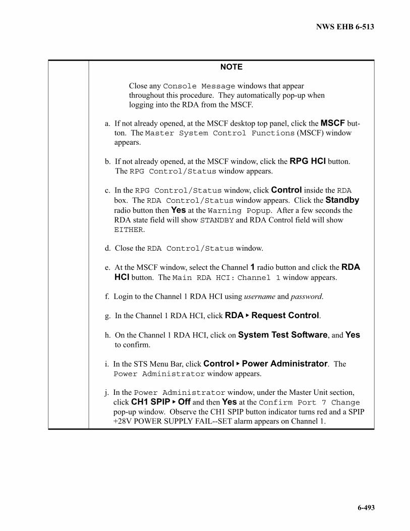
NOTE
Close any Console Message windows that appear throughout this procedure. They automatically pop-up when logging into the RDA from the MSCF.
a. If not already opened, at the MSCF desktop top panel, click the MSCF but-ton. The Master System Control Functions (MSCF) windowappears.
b. If not already opened, at the MSCF window, click the RPG HCI button.The RPG Control/Status window appears.
c. In the RPG Control/Status window, click Control inside the RDAbox. The RDA Control/Status window appears. Click the Standbyradio button then Yes at the Warning Popup. After a few seconds theRDA state field will show STANDBY and RDA Control field will showEITHER.
d. Close the RDA Control/Status window.
e. At the MSCF window, select the Channel 1 radio button and click the RDAHCI button. The Main RDA HCI: Channel 1 window appears.
f. Login to the Channel 1 RDA HCI using username and password.
g. In the Channel 1 RDA HCI, click RDA Request Control.
h. On the Channel 1 RDA HCI, click on System Test Software, and Yesto confirm.
i. In the STS Menu Bar, click Control Power Administrator. ThePower Administrator window appears.
j. In the Power Administrator window, under the Master Unit section,click CH1 SPIP Off and then Yes at the Confirm Port 7 Changepop-up window. Observe the CH1 SPIP button indicator turns red and a SPIP+28V POWER SUPPLY FAIL--SET alarm appears on Channel 1.
NWS EHB 6-513
6-494
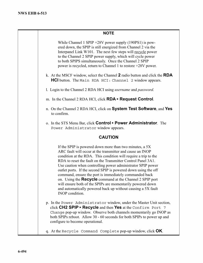
NOTE
While Channel 1 SPIP +28V power supply (190PS1) is pow-ered down, the SPIP is still energized from Channel 2 via the Interpanel Link W101. The next few steps will recycle power to the Channel 2 SPIP power supply, which will cycle power to both SPIPS simultaneously. Once the Channel 2 SPIP power is recycled, return to Channel 1 to restore +28V power.
k. At the MSCF window, select the Channel 2 radio button and click the RDAHCI button. The Main RDA HCI: Channel 2 window appears.
l. Login to the Channel 2 RDA HCI using username and password.
m. In the Channel 2 RDA HCI, click RDA Request Control.
n. On the Channel 2 RDA HCI, click on System Test Software, and Yesto confirm.
o. In the STS Menu Bar, click Control Power Administrator. ThePower Administrator window appears.
CAUTION
If the SPIP is powered down more than two minutes, a 5X ARC fault will occur at the transmitter and cause an INOP condition at the RDA. This condition will require a trip to the RDA to reset the fault on the Transmitter Control Panel 3A1. Use caution when controlling power administrator SPIP power outlet ports. If the second SPIP is powered down using the off command, ensure the port is immediately commanded back on. Using the Recycle command at the Channel 2 SPIP port will ensure both of the SPIPs are momentarily powered down and automatically powered back up without causing a 5X fault INOP condition.
p. In the Power Administrator window, under the Master Unit section,click CH2 SPIP Recycle and then Yes at the Confirm Port 7Change pop-up window. Observe both channels momentarily go INOP asboth SPIPs reboot. Allow 30 - 60 seconds for both SPIPs to power up andconfigure to become operational.
q. At the Recycle Command Complete pop-up window, click OK.
NWS EHB 6-513
6-495
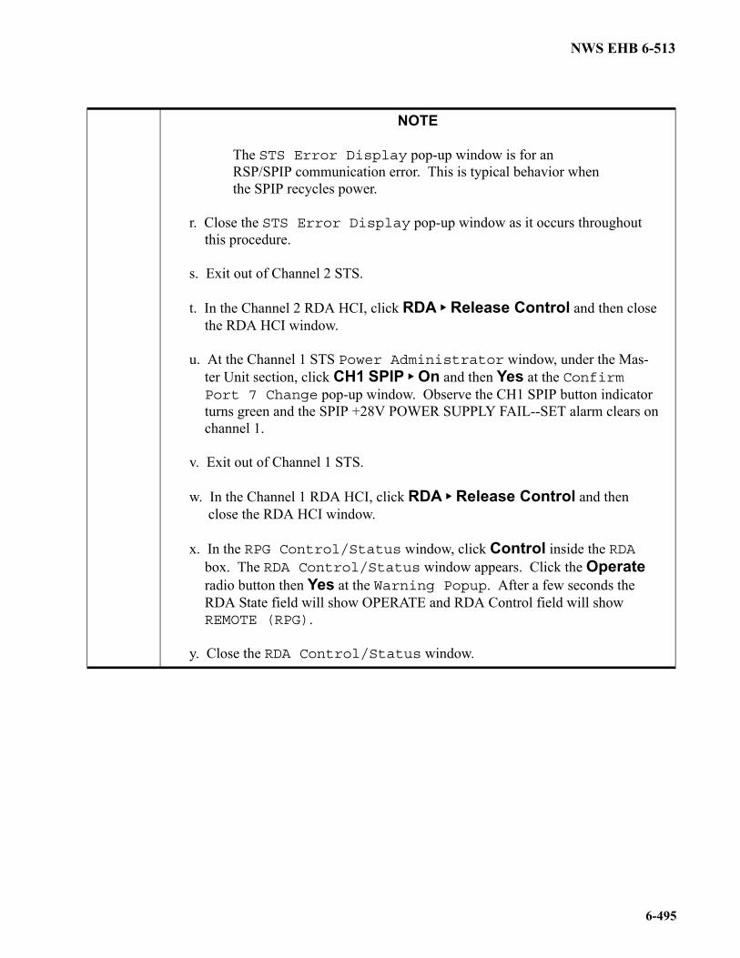
NOTE
The STS Error Display pop-up window is for an RSP/SPIP communication error. This is typical behavior when the SPIP recycles power.
r. Close the STS Error Display pop-up window as it occurs throughoutthis procedure.
s. Exit out of Channel 2 STS.
t. In the Channel 2 RDA HCI, click RDA Release Control and then closethe RDA HCI window.
u. At the Channel 1 STS Power Administrator window, under the Mas-ter Unit section, click CH1 SPIP On and then Yes at the ConfirmPort 7 Change pop-up window. Observe the CH1 SPIP button indicatorturns green and the SPIP +28V POWER SUPPLY FAIL--SET alarm clears onchannel 1.
v. Exit out of Channel 1 STS.
w. In the Channel 1 RDA HCI, click RDA Release Control and thenclose the RDA HCI window.
x. In the RPG Control/Status window, click Control inside the RDAbox. The RDA Control/Status window appears. Click the Operateradio button then Yes at the Warning Popup. After a few seconds theRDA State field will show OPERATE and RDA Control field will showREMOTE (RPG).
y. Close the RDA Control/Status window.
NWS EHB 6-513
6-496
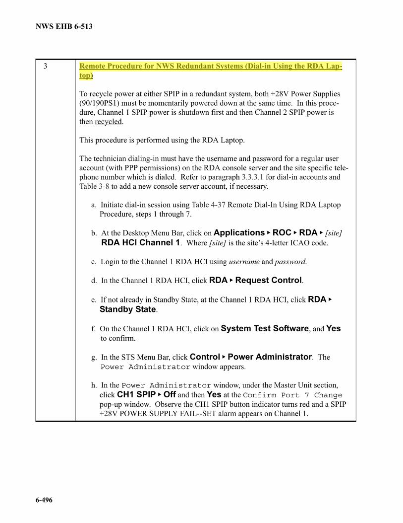
3 Remote Procedure for NWS Redundant Systems (Dial-in Using the RDA Lap-top)
To recycle power at either SPIP in a redundant system, both +28V Power Supplies (90/190PS1) must be momentarily powered down at the same time. In this proce-dure, Channel 1 SPIP power is shutdown first and then Channel 2 SPIP power is then recycled.
This procedure is performed using the RDA Laptop.
The technician dialing-in must have the username and password for a regular user account (with PPP permissions) on the RDA console server and the site specific tele-phone number which is dialed. Refer to paragraph 3.3.3.1 for dial-in accounts and Table 3-8 to add a new console server account, if necessary.
a. Initiate dial-in session using Table 4-37 Remote Dial-In Using RDA LaptopProcedure, steps 1 through 7.
b. At the Desktop Menu Bar, click on Applications ROC RDA [site]RDA HCI Channel 1. Where [site] is the site’s 4-letter ICAO code.
c. Login to the Channel 1 RDA HCI using username and password.
d. In the Channel 1 RDA HCI, click RDA Request Control.
e. If not already in Standby State, at the Channel 1 RDA HCI, click RDA
Standby State.
f. On the Channel 1 RDA HCI, click on System Test Software, and Yesto confirm.
g. In the STS Menu Bar, click Control Power Administrator. ThePower Administrator window appears.
h. In the Power Administrator window, under the Master Unit section,click CH1 SPIP Off and then Yes at the Confirm Port 7 Changepop-up window. Observe the CH1 SPIP button indicator turns red and a SPIP+28V POWER SUPPLY FAIL--SET alarm appears on Channel 1.
NWS EHB 6-513
6-497
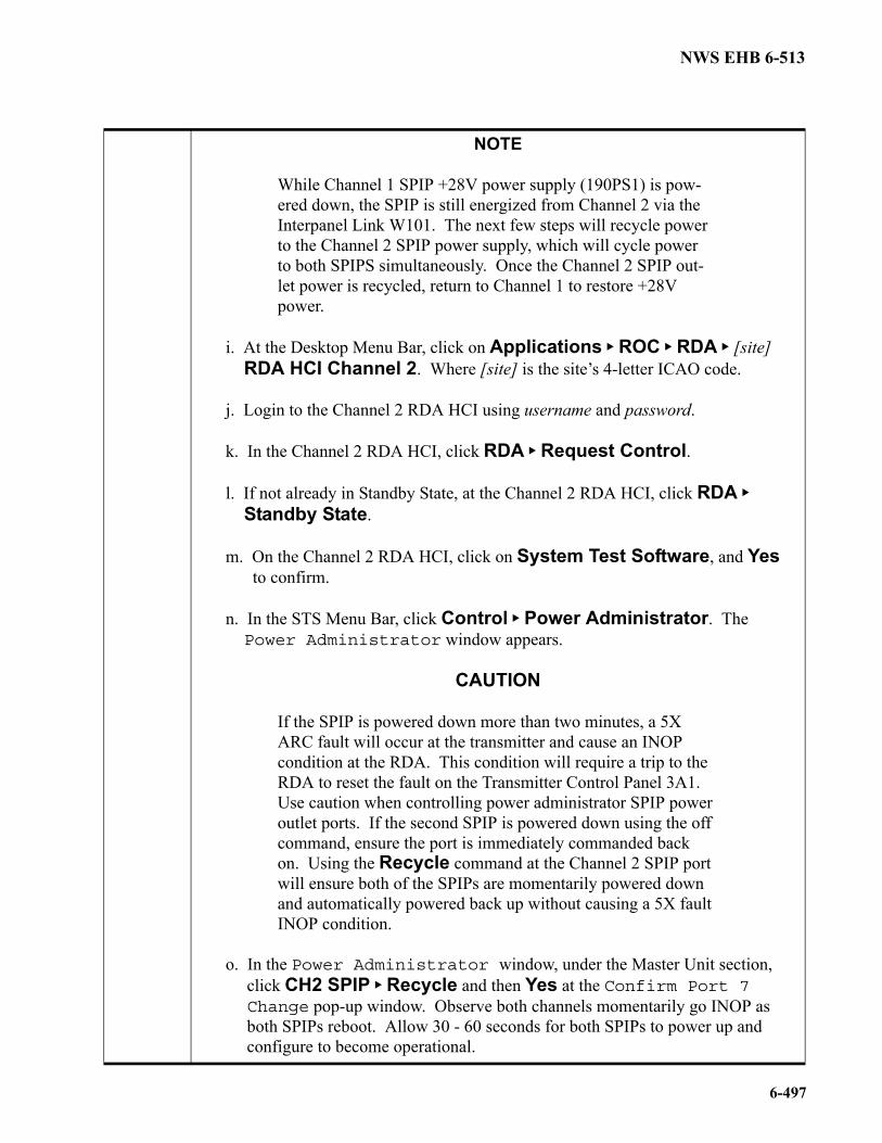
NOTE
While Channel 1 SPIP +28V power supply (190PS1) is pow-ered down, the SPIP is still energized from Channel 2 via the Interpanel Link W101. The next few steps will recycle power to the Channel 2 SPIP power supply, which will cycle power to both SPIPS simultaneously. Once the Channel 2 SPIP out-let power is recycled, return to Channel 1 to restore +28V power.
i. At the Desktop Menu Bar, click on Applications ROC RDA [site]RDA HCI Channel 2. Where [site] is the site’s 4-letter ICAO code.
j. Login to the Channel 2 RDA HCI using username and password.
k. In the Channel 2 RDA HCI, click RDA Request Control.
l. If not already in Standby State, at the Channel 2 RDA HCI, click RDA
Standby State.
m. On the Channel 2 RDA HCI, click on System Test Software, and Yesto confirm.
n. In the STS Menu Bar, click Control Power Administrator. ThePower Administrator window appears.
CAUTION
If the SPIP is powered down more than two minutes, a 5X ARC fault will occur at the transmitter and cause an INOP condition at the RDA. This condition will require a trip to the RDA to reset the fault on the Transmitter Control Panel 3A1. Use caution when controlling power administrator SPIP power outlet ports. If the second SPIP is powered down using the off command, ensure the port is immediately commanded back on. Using the Recycle command at the Channel 2 SPIP port will ensure both of the SPIPs are momentarily powered down and automatically powered back up without causing a 5X fault INOP condition.
o. In the Power Administrator window, under the Master Unit section,click CH2 SPIP Recycle and then Yes at the Confirm Port 7Change pop-up window. Observe both channels momentarily go INOP asboth SPIPs reboot. Allow 30 - 60 seconds for both SPIPs to power up andconfigure to become operational.

NWS EHB 6-513
6-498
p. At the Recycle Command Complete pop-up window, click OK.
NOTE
The STS Error Display pop-up window is for an RSP/SPIP communication error. This is typical behavior when the SPIP recycles power.
q. Close the STS Error Display pop-up window as it occurs throughoutthis procedure.
r. Exit out of Channel 2 STS.
s. In the Channel 2 RDA HCI, click RDA Release Control and then closethe RDA HCI window.
t. At the Channel 1 STS Power Administrator window, under the MasterUnit section, click CH1 SPIP On and then Yes at the Confirm Port7 Change pop-up window. Observe the CH1 SPIP button indicator turnsgreen and the SPIP +28V POWER SUPPLY FAIL--SET alarm clears on chan-nel 1.
u. Exit out of Channel 1 STS.
v. In the Main RDA HCI, click RDA Operate State.
w. In the Main RDA HCI, click RDA Release Control.
x. Terminate the dial-in session using Table 4-37 Remote Dial-In Using RDALaptop Procedure, steps 10 through 12.
NWS EHB 6-513
6-155/(6-156 blank)
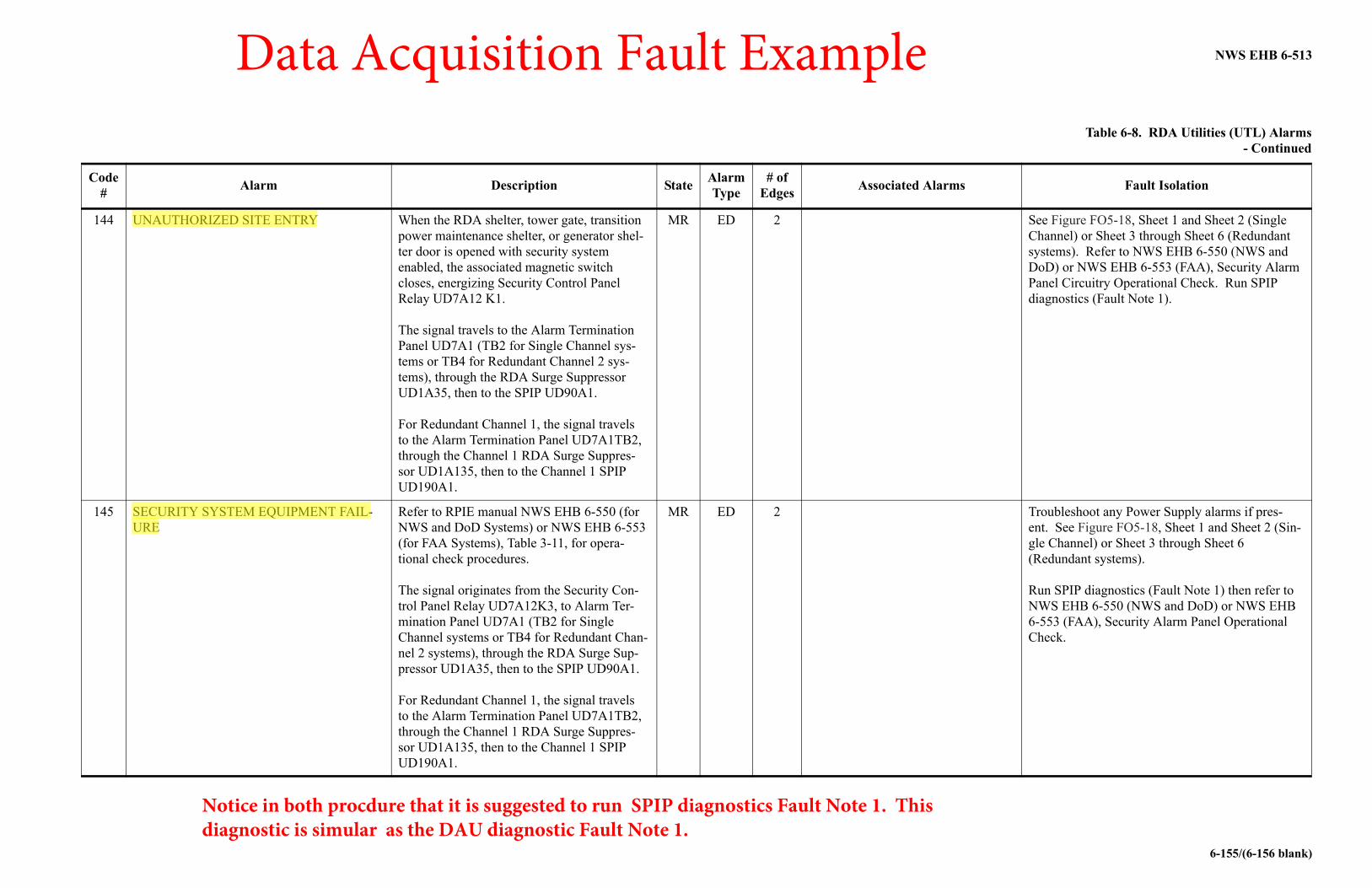
Table 6-8. RDA Utilities (UTL) Alarms - Continued
Code #
Alarm Description StateAlarmType
# of Edges
Associated Alarms Fault Isolation
144 UNAUTHORIZED SITE ENTRY When the RDA shelter, tower gate, transition power maintenance shelter, or generator shel-ter door is opened with security system enabled, the associated magnetic switch closes, energizing Security Control Panel Relay UD7A12 K1.
The signal travels to the Alarm Termination Panel UD7A1 (TB2 for Single Channel sys-tems or TB4 for Redundant Channel 2 sys-tems), through the RDA Surge Suppressor UD1A35, then to the SPIP UD90A1.
For Redundant Channel 1, the signal travels to the Alarm Termination Panel UD7A1TB2, through the Channel 1 RDA Surge Suppres-sor UD1A135, then to the Channel 1 SPIP UD190A1.
MR ED 2 See Figure FO5-18, Sheet 1 and Sheet 2 (Single Channel) or Sheet 3 through Sheet 6 (Redundant systems). Refer to NWS EHB 6-550 (NWS and DoD) or NWS EHB 6-553 (FAA), Security Alarm Panel Circuitry Operational Check. Run SPIP diagnostics (Fault Note 1).
145 SECURITY SYSTEM EQUIPMENT FAIL-URE
Refer to RPIE manual NWS EHB 6-550 (for NWS and DoD Systems) or NWS EHB 6-553 (for FAA Systems), Table 3-11, for opera-tional check procedures.
The signal originates from the Security Con-trol Panel Relay UD7A12K3, to Alarm Ter-mination Panel UD7A1 (TB2 for Single Channel systems or TB4 for Redundant Chan-nel 2 systems), through the RDA Surge Sup-pressor UD1A35, then to the SPIP UD90A1.
For Redundant Channel 1, the signal travels to the Alarm Termination Panel UD7A1TB2, through the Channel 1 RDA Surge Suppres-sor UD1A135, then to the Channel 1 SPIP UD190A1.
MR ED 2 Troubleshoot any Power Supply alarms if pres-ent. See Figure FO5-18, Sheet 1 and Sheet 2 (Sin-gle Channel) or Sheet 3 through Sheet 6 (Redundant systems).
Run SPIP diagnostics (Fault Note 1) then refer to NWS EHB 6-550 (NWS and DoD) or NWS EHB 6-553 (FAA), Security Alarm Panel Operational Check.
Notice in both procdure that it is suggested to run SPIP diagnostics Fault Note 1. This diagnostic is simular as the DAU diagnostic Fault Note 1.
Data Acquisition Fault Example
NWS EHB 6-513
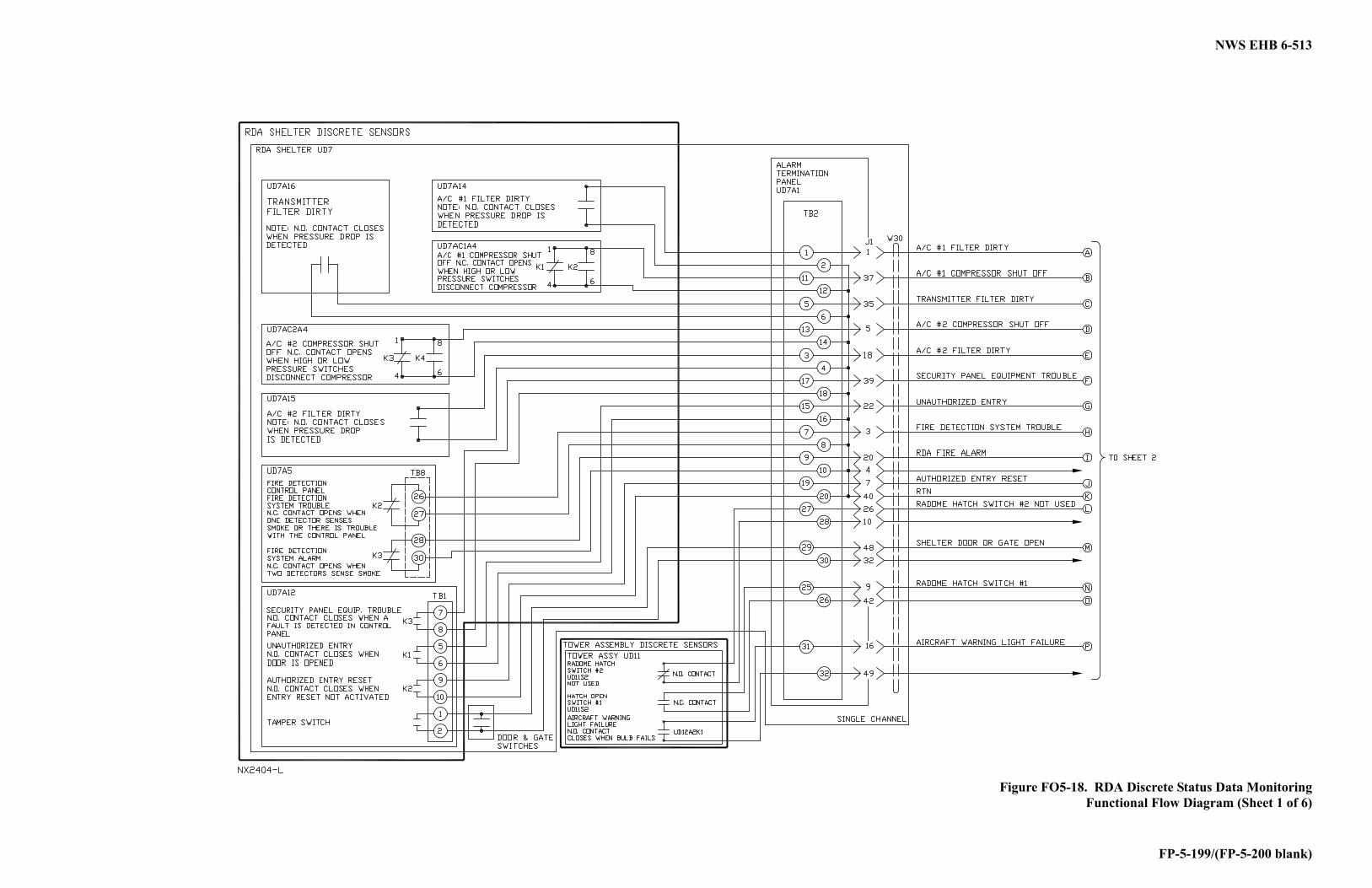
FP-5-199/(FP-5-200 blank)
Figure FO5-18. RDA Discrete Status Data MonitoringFunctional Flow Diagram (Sheet 1 of 6)
NWS EHB 6-513
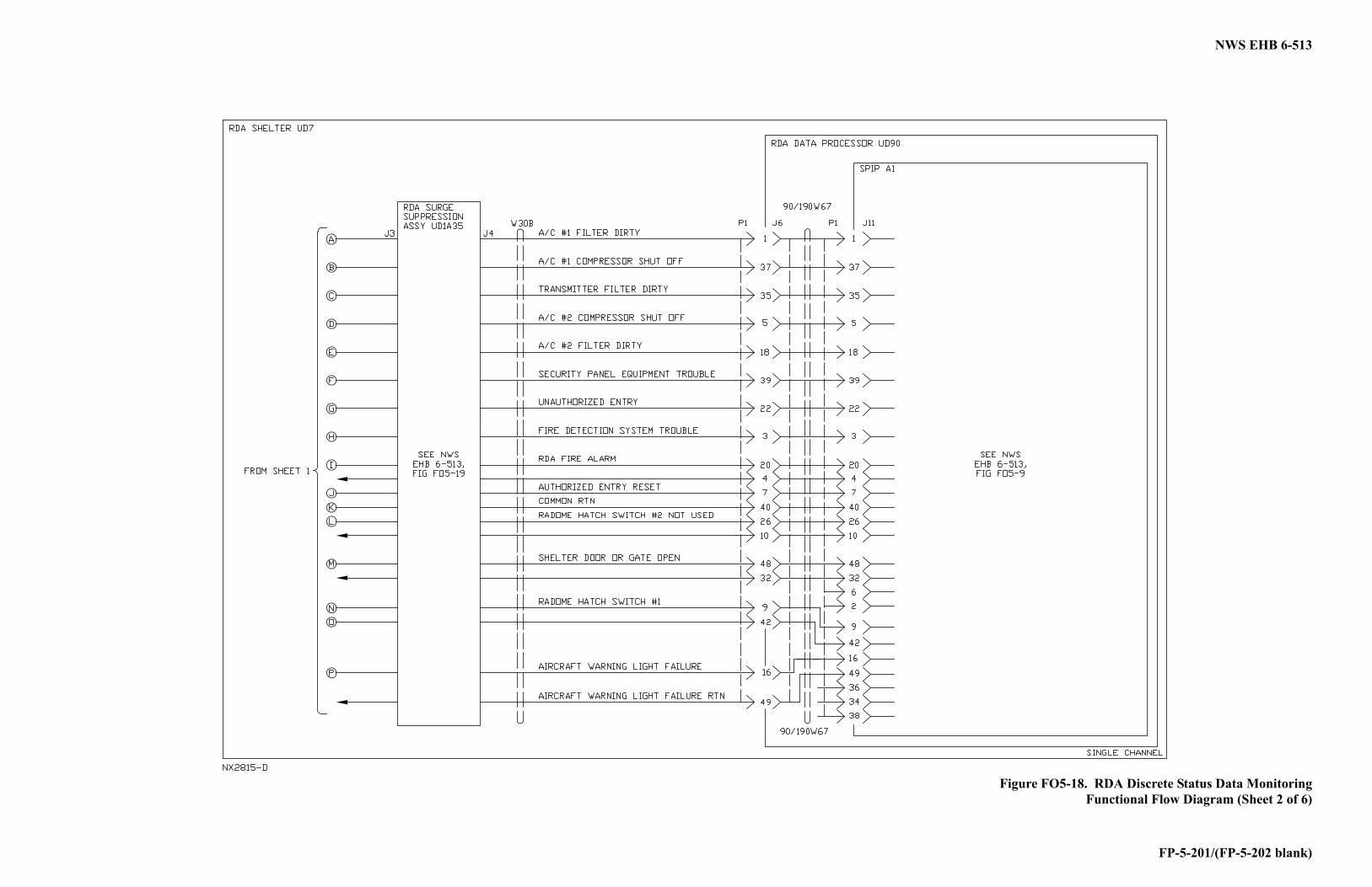
FP-5-201/(FP-5-202 blank)
Figure FO5-18. RDA Discrete Status Data MonitoringFunctional Flow Diagram (Sheet 2 of 6)