Embed Size (px)
Citation preview
Antenna System Monitoring
Application Note
Copyright RF Industries Pty Ltd 2012. Subject to change without notice.
rfiwireless.com.au 2
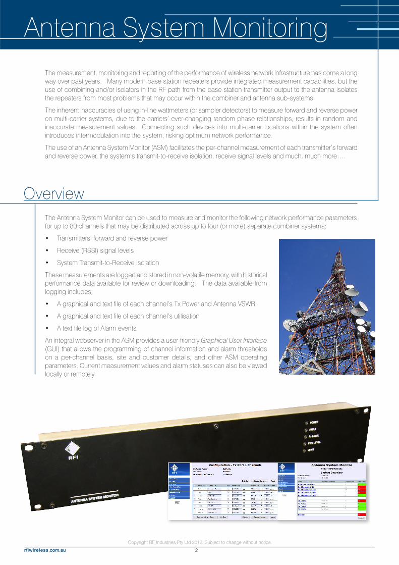
The Antenna System Monitor can be used to measure and monitor the following network performance parameters for up to 80 channels that may be distributed across up to four (or more) separate combiner systems;
• Transmitters’ forward and reverse power
• Receive (RSSI) signal levels
• System Transmit-to-Receive Isolation
These measurements are logged and stored in non-volatile memory, with historical performance data available for review or downloading. The data available from logging includes;
• A graphical and text file of each channel’s Tx Power and Antenna VSWR
• A graphical and text file of each channel’s utilisation
• A text file log of Alarm events
An integral webserver in the ASM provides a user-friendly Graphical User Interface (GUI) that allows the programming of channel information and alarm thresholds on a per-channel basis, site and customer details, and other ASM operating parameters. Current measurement values and alarm statuses can also be viewed locally or remotely.
Overview
Antenna System MonitoringThe measurement, monitoring and reporting of the performance of wireless network infrastructure has come a long way over past years. Many modern base station repeaters provide integrated measurement capabilities, but the use of combining and/or isolators in the RF path from the base station transmitter output to the antenna isolates the repeaters from most problems that may occur within the combiner and antenna sub-systems.
The inherent inaccuracies of using in-line wattmeters (or sampler detectors) to measure forward and reverse power on multi-carrier systems, due to the carriers’ ever-changing random phase relationships, results in random and inaccurate measurement values. Connecting such devices into multi-carrier locations within the system often introduces intermodulation into the system, risking optimum network performance.
The use of an Antenna System Monitor (ASM) facilitates the per-channel measurement of each transmitter’s forward and reverse power, the system’s transmit-to-receive isolation, receive signal levels and much, much more….

Copyright RF Industries Pty Ltd 2012. Subject to change without notice.
rfiwireless.com.au3
RF alarm events are captured and recorded, and can be reported via several methods;
• Dry-relay summary alarm contacts
• SNMP Alarm Traps
• Email (SMTP) notifications
• Network Manager messages
• Channel Alarm Module
The channel bandwidth and modulation type of each channel is also configurable via the GUI. This allows combinations of FDMA and TDMA modulations and protocols (i.e. Analogue, P25P1, P25P2, TETRA, DMR, etc) to be measured and monitored using different algorithms within the ASM.
An optional Channel Alarm Module (CAM) unit is available that allows ten (10) channels’ alarms to be mapped to individual relay outputs on the CAM. Individual base station “PTT” lines can also be monitored by the CAM, ensuring an RF output total failure in a base station can also be discerned from the ASM measurements. Four (4) independent alarm inputs are also provided on a CAM, allowing the monitoring of site alarms (‘door open’, ‘battery low’, ‘generator fuel low’, etc).
Up to ten (10) CAM units may be connected to an ASM using supplied interconnect cables, and the ASM recognises CAMs automatically when they are connected and they then appear in the ASM GUI for configuration, status monitoring and reporting.
Copyright RF Industries Pty Ltd 2012. Subject to change without notice.
rfiwireless.com.au 4
Applications
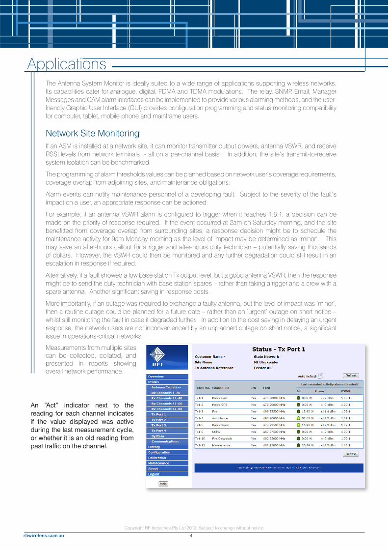
An “Act” indicator next to the reading for each channel indicates if the value displayed was active during the last measurement cycle, or whether it is an old reading from past traffic on the channel.
Network Site MonitoringIf an ASM is installed at a network site, it can monitor transmitter output powers, antenna VSWR, and receive RSSI levels from network terminals - all on a per-channel basis. In addition, the site’s transmit-to-receive system isolation can be benchmarked.
The programming of alarm thresholds values can be planned based on network user’s coverage requirements, coverage overlap from adjoining sites, and maintenance obligations.
Alarm events can notify maintenance personnel of a developing fault. Subject to the severity of the fault’s impact on a user, an appropriate response can be actioned.
For example, if an antenna VSWR alarm is configured to trigger when it reaches 1.8:1, a decision can be made on the priority of response required. If the event occurred at 2am on Saturday morning, and the site benefitted from coverage overlap from surrounding sites, a response decision might be to schedule the maintenance activity for 9am Monday morning as the level of impact may be determined as ‘minor’. This may save an after-hours callout for a rigger and after-hours duty technician – potentially saving thousands of dollars. However, the VSWR could then be monitored and any further degradation could still result in an escalation in response if required.
Alternatively, if a fault showed a low base station Tx output level, but a good antenna VSWR, then the response might be to send the duty technician with base station spares – rather than taking a rigger and a crew with a spare antenna. Another significant saving in response costs.
More importantly, if an outage was required to exchange a faulty antenna, but the level of impact was ‘minor’, then a routine outage could be planned for a future date – rather than an ‘urgent’ outage on short notice – whilst still monitoring the fault in case it degraded further. In addition to the cost saving in delaying an urgent response, the network users are not inconvenienced by an unplanned outage on short notice, a significant issue in operations-critical networks.
Measurements from multiple sites can be collected, collated, and presented in reports showing overall network performance.
The Antenna System Monitor is ideally suited to a wide range of applications supporting wireless networks. Its capabilities cater for analogue, digital, FDMA and TDMA modulations. The relay, SNMP, Email, Manager Messages and CAM alarm interfaces can be implemented to provide various alarming methods, and the user-friendly Graphic User Interface (GUI) provides configuration programming and status monitoring compatibility for computer, tablet, mobile phone and mainframe users.

Copyright RF Industries Pty Ltd 2012. Subject to change without notice.
rfiwireless.com.au5
A comprehensive Alarm Log is also available to provide a history of alarm events. This log can also be downloaded as a CSV text file and used to create KPI reports on the number of faults (MTBF), fault restoration times (MTTR). When coupled with the History Log, this could be used to provide a series of datasets on recurring faults, unreliable equipments and related maintenance metrics.
If intermittent or sagging RF output power is suspected, the Tx Power History Chart can show the performance of the channels over a selected period of time.
The time and date stamped History Log can be viewed to identify or analyse specific event times. The log can also be downloaded as a CSV text file and used to create customised reports.
Network Availability (2011/12)
Available (97.1%)
Outages (2.9%)
Alarms by Type (2011/12)
Tx Alarms
Rx Alarms
Door Alarms
Fuel Alarms
OMCS & PMCS Software Integration – Manager MessagesThe ASM also offers Manager Messages that are UDP IP message packets that contain Traffic and Status data created by the ASM measurement cycles. These ASM messages can be sent to nominated IP addresses where they can be processed and the data utilised in higher-level application software.
Total Alarm Hours (2011/12)
Tx Outages (234)
Rx Outages (23)
Total (257)
Copyright RF Industries Pty Ltd 2012. Subject to change without notice.
rfiwireless.com.au 6
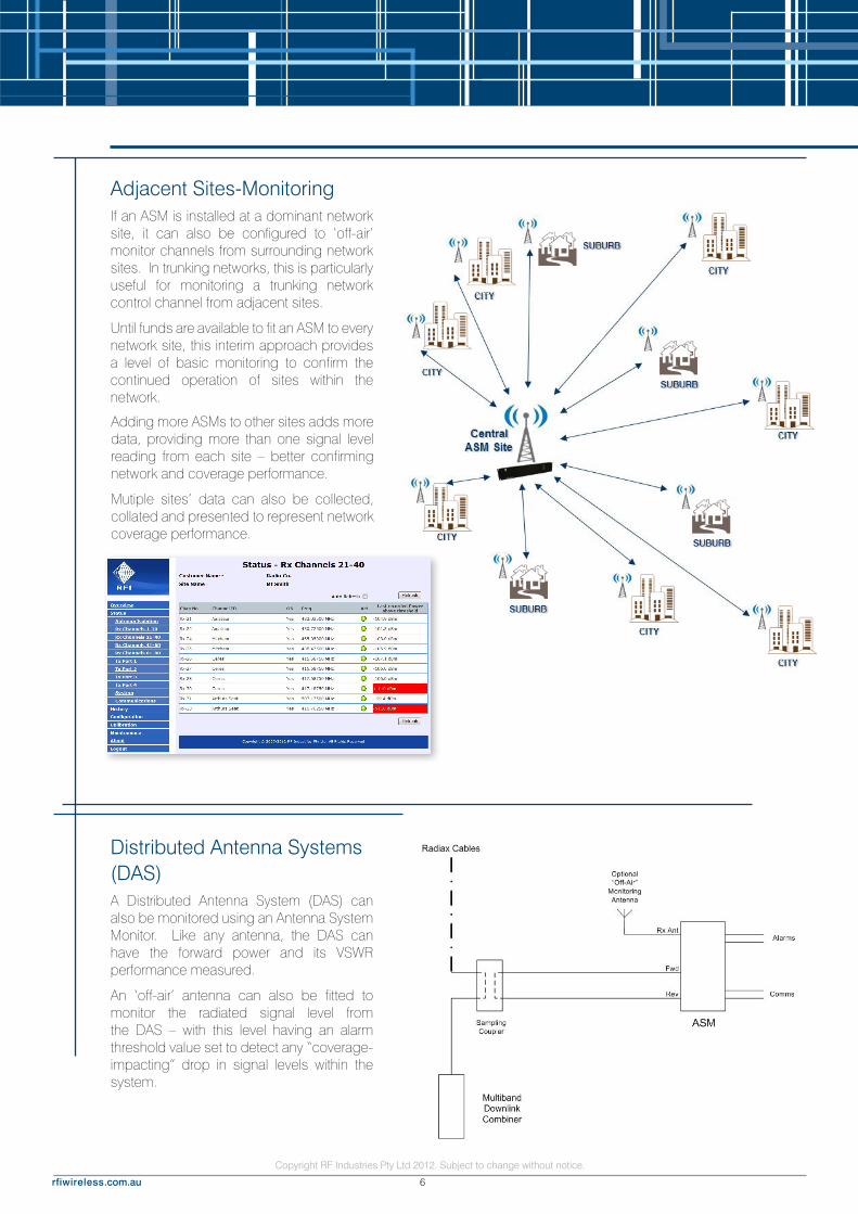
Adjacent Sites-MonitoringIf an ASM is installed at a dominant network site, it can also be configured to ‘off-air’ monitor channels from surrounding network sites. In trunking networks, this is particularly useful for monitoring a trunking network control channel from adjacent sites.
Until funds are available to fit an ASM to every network site, this interim approach provides a level of basic monitoring to confirm the continued operation of sites within the network.
Adding more ASMs to other sites adds more data, providing more than one signal level reading from each site – better confirming network and coverage performance.
Mutiple sites’ data can also be collected, collated and presented to represent network coverage performance.
Distributed Antenna Systems (DAS)A Distributed Antenna System (DAS) can also be monitored using an Antenna System Monitor. Like any antenna, the DAS can have the forward power and its VSWR performance measured.
An ‘off-air’ antenna can also be fitted to monitor the radiated signal level from the DAS – with this level having an alarm threshold value set to detect any “coverage-impacting” drop in signal levels within the system.
Copyright RF Industries Pty Ltd 2012. Subject to change without notice.
rfiwireless.com.au7
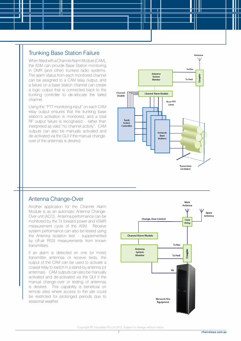
Trunking Base Station FailureWhen fitted with a Channel Alarm Module (CAM), the ASM can provide Base Station monitoring in DMR (and other) trunked radio systems. The alarm status from each monitored channel can be assigned to a CAM relay output, and a failure on a base station channel can create a logic output that is connected back to the trunking controller to de-allocate the failed channel.
Using the “PTT monitoring input” on each CAM relay output ensures that the trunking base station’s activation is monitored, and a total RF output failure is recognised – rather than interpreted as valid “no channel activity”. CAM outputs can also be manually activated and de-activated via the GUI if the manual change-over of the antennas is desired.
Antenna Change-OverAnother application for the Channel Alarm Module is as an automatic Antenna Change-Over unit (ACO). Antenna performance can be monitored by the Tx forward power and VSWR measurement cycle of the ASM. Receive system performance can also be tested using the Antenna Isolation test – supplemented by off-air RSSI measurements from known transmitters.
If an alarm is detected on one (or more) transmitter antennas or receive tests, the output of the CAM can be used to activate a coaxial relay to switch in a stand-by antenna (or antennas). CAM outputs can also be manually activated and de-activated via the GUI if the manual change-over or testing of antennas is desired. This capability is beneficial on remote sites where access to the site could be restricted for prolonged periods due to seasonal weather.
Copyright RF Industries Pty Ltd 2012. Subject to change without notice.
rfiwireless.com.au 8
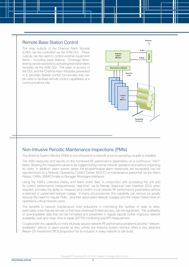
Remote Base Station ControlThe relay outputs of the Channel Alarm Module (CAM) can be controlled via the ASM GUI. These outputs can be used to control external equipment items – including base stations. Coverage drive-testing can be assisted by activating test transmitters remotely via the ASM GUI. The ease of access of the GUI, and the Channel Alarm Modules presented in it, provides flexible control functionality that can be used to facilitate remote control capabilities at a communications site.
Non-Intrusive Periodic Maintenance Inspections (PMIs)The Antenna System Monitor (ASM) is non-intrusive to a network once its sampling coupler is installed.
The ASM measures and reports on the monitored RF performance parameters on a continuous “24x7” basis, allowing the measured values to be logged during normal network operation and without impacting its users. In addition, alarm events (when the programmable alarm thresholds are exceeded) can be reported back to a Network Operations Control Center (NOCC) or maintenance personnel via the Alarm Relays, CAMs, SNMP, Emails or Manager Messages interfaces.
Using the ASM’s collected History and Alarm event data, in conjunction with accessing the unit and its current performance measurements “real-time” via its friendly Graphical User Interface (GUI) when required, provides the ability to measure and confirm most network RF performance parameters without a planned or unplanned network outage. In many circumstances, this capability can remove (or greatly reduce) the need for regular PMIs - and their associated network outages and the impact these have on operations-critical network users.
The benefits in network maintenance cost reductions in minimising the number of visits to sites, particularly ones that are remote or that have otherwise limited access, can be significant. The availability of downloadable data that can be formatted and presented in regular reports further improves network availability, fault and mean time to repair (MTTR) monitoring and KPI measurement.
Coupled with the capability to more intuitively assess network RF performance problems and the “network-availability” effects of alarm events as they unfold, the Antenna System Monitor offers a very attractive Return-On-Investment (ROI) proposition for its inclusion in every network or site build.
Copyright RF Industries Pty Ltd 2012. Subject to change without notice.
rfiwireless.com.au9
New Features, Upgrades, and DocumentationsThere is an active product development plan for the Antenna System Monitor. New features are available in regular firmware releases. Firmware updates can be easily uploaded (locally or remotely) to an ASM. Firmware update files, SNMP MIB files, Service Bulletins and User Manuals are available in the ‘Monitoring’ products category at www.rfiwireless.com.au
• Allows most PMI’s to be performed non-intrusively, without a site outage impacting network users (i.e. no more scheduled network outages)
• Measure and monitor the output of high power multi-carrier transmit combiners on a per-channel basis – without the limitations of in-line wattmeters and RF “samplers”
• Measure and monitor other network RF parameters (receive levels, system isolation, etc)
• Store historical data for later display or download
• 24x7 non-intrusive monitoring and the setting of minimum and/or maximum alarm thresholds allows the speedy detection and notification of performance-impacting changes in the networks performance
• Configuration data (frequencies, etc) is easily entered via an integral webserver GUI
• Allows intuitive assessment of site faults prior to despatching personnel to site
• Assists in determining the need for specialised personnel (i.e. riggers) and likely required spares (such as antennas) to be determined prior to travelling to site in response to a reported fault, minimising unnecessary maintenance costs.
• Reduces maintenance effort by enabling better analysis of the likely fault cause prior to deploying resources to site, and allows appropriate spares to be taken to site
• Allows earlier planning of network outages if required for fault rectification. Reduces ‘unplanned’ outages on short notice
• Detects the onset of fault conditions “as they occur” and often before network user’s notice the impact of the fault – allowing a faster response to be initiated and resulting in better Mean Time To Repair (MTTR) performance to be achieved
• Facilitates a more detailed assessment of the impact of the fault on network performance. Is it a minor reduction of coverage, is it on just one channel, or is it a more extensive impact on the network’s grade of service?
• Provides detailed data of ongoing network performance, faults and restorations – within the RF environment. Downloadable log files allow the importation and processing of data into spreadsheets, producing network performance, maintenance and other KPI reports.
Features and Benefits

Copyright RF Industries Pty Ltd 2012. Subject to change without notice.
rfiwireless.com.au 10
Local Support
NSW99 Station RoadSeven Hills NSW 2147Phone: (02) 8814 2300Fax: (02) 9630 0844
VIC46 Corporate BoulevardBayswater VIC 3153Phone: (03) 9751 7500Fax: (03) 9751 7588
WAUnit 3, 35 Colin Jamieson DriveWelshpool, WA, 6106, AustraliaPhone: (08) 9331 0600Fax: (08) 9311 0688
QLD and International Sales30 Raubers RoadBanyo QLD 4014Phone: (07) 3621 9400
Fax: (07) 3252 5505
International Support
RFI EMEA (UK)Bicester Innovation CentreCommerce HouseTelford RoadBicester OX26 4LDUnited KingdomPhone: +44 (0) 1869 255 772
RFI Americas2023 Case Parkway NorthTwinsburg OH 44087 USAPhone: +1 330 486 0706Fax: +1 330 486 0705
RFI New ZealandPO Box 38-626Howick Auckland NZPhone: +64 9 537 2683Fax: +64 9 537 2684
AN-4129-1
WIRELESS
www.rfiwireless.com.au