Embed Size (px)
Citation preview
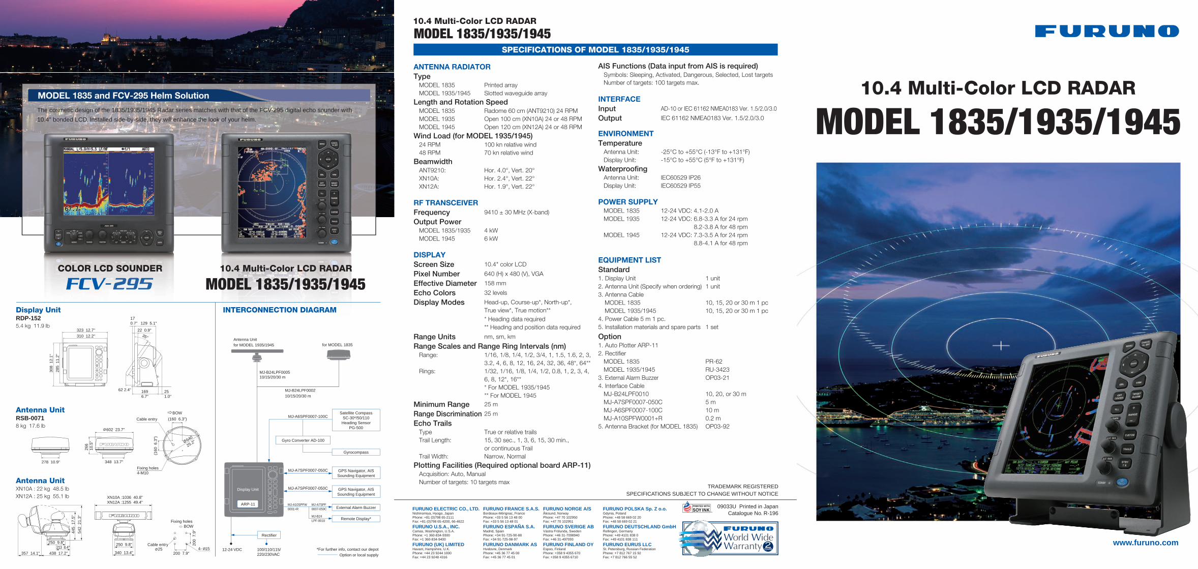
10.4 Multi-Color LCD RADAR
10.4 Multi-Color LCD RADAR
MODEL 1835/1935/1945
MODEL 1835/1935/1945SPECIFICATIONS OF MODEL 1835/1935/1945
ANTENNA RADIATORType MODEL 1835 Printed array MODEL 1935/1945 Slotted waveguide array
Length and Rotation Speed MODEL 1835 Radome 60 cm (ANT9210) 24 RPM MODEL 1935 Open 100 cm (XN10A) 24 or 48 RPM MODEL 1945 Open 120 cm (XN12A) 24 or 48 RPM
Wind Load (for MODEL 1935/1945) 24 RPM 100 kn relative wind 48 RPM 70 kn relative wind
Beamwidth ANT9210: Hor. 4.0°, Vert. 20° XN10A: Hor. 2.4°, Vert. 22° XN12A: Hor. 1.9°, Vert. 22°
RF TRANSCEIVERFrequency 9410 ± 30 MHz (X-band)
Output Power MODEL 1835/1935 4 kW MODEL 1945 6 kW
DISPLAYScreen Size 10.4" color LCD
Pixel Number 640 (H) x 480 (V), VGA
Effective Diameter 158 mm
Echo Colors 32 levels
Display Modes Head-up, Course-up*, North-up*, True view*, True motion**
* Heading data required ** Heading and position data required
Range Units nm, sm, km
Range Scales and Range Ring Intervals (nm) Range: 1/16, 1/8, 1/4, 1/2, 3/4, 1, 1.5, 1.6, 2, 3,
3.2, 4, 6, 8, 12, 16, 24, 32, 36, 48*, 64** Rings: 1/32, 1/16, 1/8, 1/4, 1/2, 0.8, 1, 2, 3, 4,
6, 8, 12*, 16** * For MODEL 1935/1945 ** For MODEL 1945
Minimum Range 25 m
Range Discrimination 25 m
Echo Trails Type True or relative trails Trail Length: 15, 30 sec., 1, 3, 6, 15, 30 min.,
or continuous Trail Trail Width: Narrow, Normal
Plotting Facilities (Required optional board ARP-11) Acquisition: Auto, Manual Number of targets: 10 targets max
AIS Functions (Data input from AIS is required) Symbols: Sleeping, Activated, Dangerous, Selected, Lost targets Number of targets: 100 targets max.
INTERFACEInput AD-10 or IEC 61162 NMEA0183 Ver. 1.5/2.0/3.0
Output IEC 61162 NMEA0183 Ver. 1.5/2.0/3.0
ENVIRONMENTTemperature Antenna Unit: -25°C to +55°C (-13°F to +131°F) Display Unit: -15°C to +55°C (5°F to +131°F)
Waterproofing Antenna Unit: IEC60529 IP26 Display Unit: IEC60529 IP55
POWER SUPPLY MODEL 1835 12-24 VDC: 4.1-2.0 A MODEL 1935 12-24 VDC: 6.8-3.3 A for 24 rpm 8.2-3.8 A for 48 rpm MODEL 1945 12-24 VDC: 7.3-3.5 A for 24 rpm 8.8-4.1 A for 48 rpm
EQUIPMENT LISTStandard1. Display Unit 1 unit2. Antenna Unit (Specify when ordering) 1 unit3. Antenna Cable MODEL 1835 10, 15, 20 or 30 m 1 pc MODEL 1935/1945 10, 15, 20 or 30 m 1 pc4. Power Cable 5 m 1 pc.5. Installation materials and spare parts 1 set
Option1. Auto Plotter ARP-112. Rectifier MODEL 1835 PR-62 MODEL 1935/1945 RU-34233. External Alarm Buzzer OP03-214. Interface Cable MJ-B24LPF0010 10, 20, or 30 m MJ-A7SPF0007-050C 5 m MJ-A6SPF0007-100C 10 m MJ-A10SPFW0001+R 0.2 m5. Antenna Bracket (for MODEL 1835) OP03-92
FURUNO U.S.A., INC.Camas, Washington, U.S.A.Phone: +1 360-834-9300Fax: +1 360-834-9400
FURUNO ELECTRIC CO., LTD.Nishinomiya, Hyogo, JapanPhone: +81 (0)798 65-2111Fax: +81 (0)798 65-4200, 66-4622
FURUNO (UK) LIMITEDHavant, Hampshire, U.K.Phone: +44 23 9244 1000Fax: +44 23 9248 4316
FURUNO FRANCE S.A.S.Bordeaux-Mérignac, FrancePhone: +33 5 56 13 48 00Fax: +33 5 56 13 48 01
FURUNO ESPAÑA S.A.Madrid, SpainPhone: +34 91-725-90-88Fax: +34 91-725-98-97
FURUNO DANMARK AS Hvidovre, DenmarkPhone: +45 36 77 45 00Fax: +45 36 77 45 01
FURUNO NORGE A/SÅlesund, NorwayPhone: +47 70 102950Fax: +47 70 102951
FURUNO SVERIGE ABVästra Frölunda, SwedenPhone: +46 31-7098940Fax: +46 31-497093
FURUNO FINLAND OYEspoo, FinlandPhone: +358 9 4355 670Fax: +358 9 4355 6710
FURUNO POLSKA Sp. Z o.o.Gdynia, PolandPhone: +48 58 669 02 20Fax: +48 58 669 02 21
FURUNO DEUTSCHLAND GmbHRellingen, GermanyPhone: +49 4101 838 0Fax: +49 4101 838 111
FURUNO EURUS LLCSt. Petersburg, Russian FederationPhone: +7 812 767 15 92Fax: +7 812 766 55 52
TRADEMARK REGISTEREDSPECIFICATIONS SUBJECT TO CHANGE WITHOUT NOTICE
09033U Printed in JapanCatalogue No. R-196
www.furuno.com
COLOR LCD SOUNDER 10.4 Multi-Color LCD RADAR
MODEL 1835/1935/1945
MODEL 1835 and FCV-295 Helm Solution
The cosmetic design of the 1835/1935/1945 Radar series matches with that of the FCV-295 digital echo sounder with
10.4" bonded LCD. Installed side-by-side, they will enhance the look of your helm.
285
11.
2"
310 12.2"
323 12.7"
308
12.
1"
1696.7"
129 5.1"170.7"
22 0.9"35°
251.0"
62 2.4"
BOW
Cable entry
278 10.9"
602 23.7"
348 13.7"
266
10.5
"
Cable entry (160 6.3")
(160
6.3
")
Fixing holes4-M10
640
25.2"
BOW
445
17.
5"
357 14.1"
542
21.
3"
250 9.8"213 8.4"
438 17.2" 340 13.4"
250 9.8"
XN10A :1036 40.8"XN12A :1255 49.4"
4- 15
Fixing holes
200 7.9"
200
7.9
"
25 100/110/115/220/230VAC
12-24 VDC
MJ-B24LPF000210/15/20/30 m
MJ-B24LPF000510/15/20/30 m
MJ-A10SPFW0001+R
MJ-A7SPF0007-050C
MJ-B24LPF-0010
MJ-A7SPF0007-050C
MJ-A7SPF0007-050C
MJ-A6SPF0007-100C
Display Unit RDP-1525.4 kg 11.9 lb
Antenna Unit RSB-00718 kg 17.6 lb
Antenna UnitXN10A : 22 kg 48.5 lbXN12A : 25 kg 55.1 lb
Display Unit
ARP-11
GPS Navigator, AISSounding Equipment
Satellite CompassSC-30*/50/110
Heading SensorPG-500
*For further info, contact our depotOption or local supply
Gyro Converter AD-100
Rectifier
GPS Navigator, AISSounding Equipment
Gyrocompass
External Alarm Buzzer
for MODEL 1835
Remote Display*
INTERCONNECTION DIAGRAM
Antenna Unitfor MODEL 1935/1945
Target A1
Target A2
Target A3
Data off
RainControlON
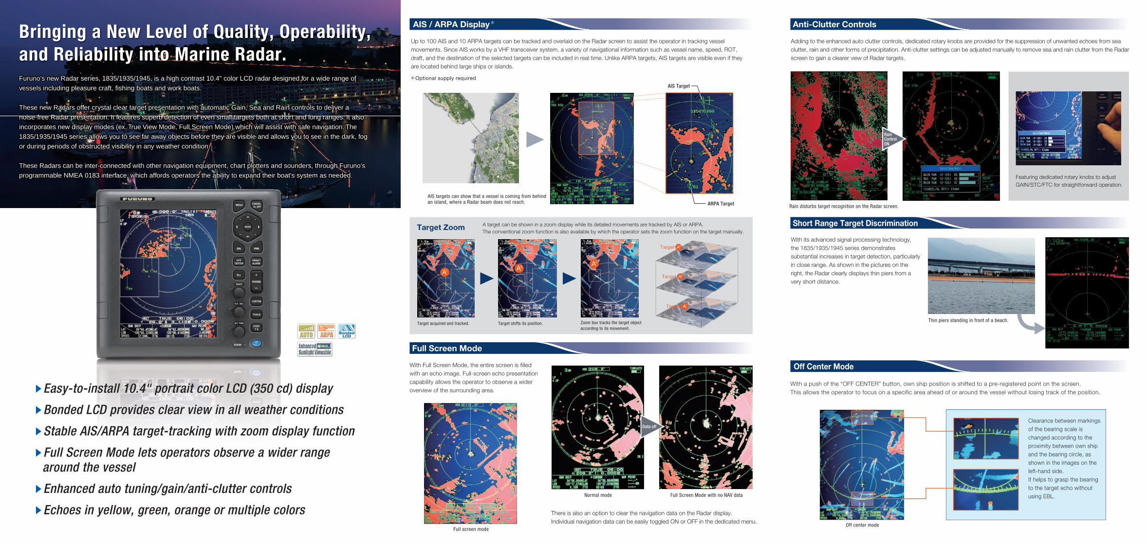
sEasy-to-install 10.4" portrait color LCD (350 cd) display
sBonded LCD provides clear view in all weather conditions
sStable AIS/ARPA target-tracking with zoom display function
sFull Screen Mode lets operators observe a wider range around the vessel
sEnhanced auto tuning/gain/anti-clutter controls
sEchoes in yellow, green, orange or multiple colors
With Full Screen Mode, the entire screen is filled with an echo image. Full-screen echo presentation capability allows the operator to observe a wider overview of the surrounding area.
Full Screen Mode
Short Range Target Discrimination
With a push of the “OFF CENTER” button, own ship position is shifted to a pre-registered point on the screen.This allows the operator to focus on a specific area ahead of or around the vessel without losing track of the position.
Clearance between markings of the bearing scale is changed according to the proximity between own ship and the bearing circle, as shown in the images on the left-hand side.It helps to grasp the bearing to the target echo without using EBL.Full Screen Mode with no NAV data
Off center mode
Normal mode
Bringing a New Level of Quality, Operability, and Reliability into Marine Radar.Furuno's new Radar series, 1835/1935/1945, is a high contrast 10.4" color LCD radar designed for a wide range of
vessels including pleasure craft, fishing boats and work boats.
These new Radars offer crystal clear target presentation with automatic Gain, Sea and Rain controls to deliver a
noise-free Radar presentation. It features superb detection of even small targets both at short and long ranges. It also
incorporates new display modes (ex. True View Mode, Full Screen Mode) which will assist with safe navigation. The
1835/1935/1945 series allows you to see far away objects before they are visible and allows you to see in the dark, fog
or during periods of obstructed visibility in any weather condition.
These Radars can be inter-connected with other navigation equipment, chart plotters and sounders, through Furuno's
programmable NMEA 0183 interface, which affords operators the ability to expand their boat's system as needed.
Thin piers standing in front of a beach.
There is also an option to clear the navigation data on the Radar display. Individual navigation data can be easily toggled ON or OFF in the dedicated menu.
With its advanced signal processing technology, the 1835/1935/1945 series demonstrates substantial increases in target detection, particularly in close range. As shown in the pictures on the right, the Radar clearly displays thin piers from a very short distance.
Off Center Mode
Full screen mode
Adding to the enhanced auto clutter controls, dedicated rotary knobs are provided for the suppression of unwanted echoes from sea clutter, rain and other forms of precipitation. Anti-clutter settings can be adjusted manually to remove sea and rain clutter from the Radar screen to gain a clearer view of Radar targets.
Anti-Clutter Controls
Rain disturbs target recognition on the Radar screen.
Featuring dedicated rotary knobs to adjust GAIN/STC/FTC for straightforward operation.
Up to 100 AIS and 10 ARPA targets can be tracked and overlaid on the Radar screen to assist the operator in tracking vessel movements. Since AIS works by a VHF transceiver system, a variety of navigational information such as vessel name, speed, ROT, draft, and the destination of the selected targets can be included in real time. Unlike ARPA targets, AIS targets are visible even if they are located behind large ships or islands.
Optional supply required
AIS targets can show that a vessel is coming from behind an island, where a Radar beam does not reach. ARPA Target
AIS Target
Target Zoom A target can be shown in a zoom display while its detailed movements are tracked by AIS or ARPA. The conventional zoom function is also available by which the operator sets the zoom function on the target manually.
Target acquired and tracked. Target shifts its position. Zoom box tracks the target object according to its movement.
AIS / ARPA Display