Embed Size (px)
Citation preview

Antenna DesignSenior Design, Fall 2011
Supervisors: Branislav Notaros, Olivera Notaros, Nada Sekeljic
Electrical Students: Nate Hufnagel, John James, Prabhat Lamsal
Mechanical Students: Steve Johnson, Robert Meyer

Antenna Design Team
Nate Hufnagel John James Prabhat LamsalSteve Johnson
•Electrical
•Team Leader
•Antenna Design
•Electrical
•Antenna Design
•Electrical
•Antenna Design
•Mechanical
•Antenna Fabrication

Project Goals
• Design, optimize and fabricate a family of horn
antennas, waveguides and coaxial to monopole
feeds that effectively cover the microwave
spectrum from 1 – 20 GHz
– Design and optimization was accomplished using WIPL-D
software
– Steve Johnson is currently fabricating our first two
standard gain horn antennas

Project Goals
• Produce antennas that are as good or better than
those already on the market
• Produce antennas at a fraction of the cost of those
already on the marketalready on the market
– Comparable standard gain horn antennas cost around
$700.00
– Our standard gain horn antenna cost $9.83 to produce

Standard Gain Horn Antenna Constraints
• Operate around 10 GHz
• Maintain 20 dB gain over the complete operational
frequency range
• Maintain a voltage standing wave ratio (VSWR) of less
than 2 over the complete operational frequency range
• Maintain a half power beamwidth (HPBW) that is less
than 20 degrees over the complete operational
frequency range

Why We Chose Horn Antennas
• Horn antennas have a directional radiation pattern
• Ability to achieve high gain
– Horn antennas have very little loss, so the gain of the antenna is nearly its directivity antenna is nearly its directivity
• Input impedance varies slowly over a wide frequency range
– Sufficient power will be delivered to the antenna
• Fabrication is somewhat simple and inexpensive

Simulation and Actual Results
• Conductivity
– We used perfect electric conductors (PEC) to model our antenna
– Our antenna is aluminum
• Antenna Excitation• Antenna Excitation
– WIPL-D models our feed as a simple delta pulse generator
– We will feed our antenna with 2.4 mm connector and coaxial cable
• This will lead to losses

WIPL-D Software
• 3-D Electromagnetic Solver
• Able to compute the radiation pattern of any antenna
• Parametrically sweeps multiple dimensions of Antenna for optimal
radiation
Our Antenna in WIPL-D

Constraints
• 20 dB gain over frequency range of 8-12 GHz
• VSWR to remain under 2 for 8-12 GHz
• HPBW (Half-Power Beam Width) of less than 20 degrees

VSWRVSWRVSWR stands for voltage standing wave ratio. It is a function of the reflection coefficient, which describes the power reflected from the antenna.
• Γ(gamma) is the reflection coefficient. The VSWR is always a real and positive number for the antennas.
• The smaller the VSWR is, the better the antenna is matched to the transmission line and more power delivered to the antenna. In our design we have VSWR of below 2 (1.97) over the frequency range of 8-12 GHZ.

VSWR (Final Dimensions)VSWR (Final Dimensions)
• VSWR remained below 2 for entire 8-12 GHz range

Gain (Final Dimensions)
• Gain over 8-12 GHz range
• Maintained over 20.66 dB reaching maximum of 23.32 dB
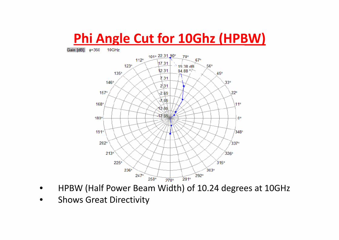
Phi Angle Cut for 10Ghz (HPBW)
• HPBW (Half Power Beam Width) of 10.24 degrees at 10GHz
• Shows Great Directivity

Final 3-D Radiation Plot (10 GHz)
•3-D Radiation Plot of Far-Field using WIPL-D

Testing TheTesting The AntennaAntenna
• After fabrication is complete , we are going to characterize our
antenna’s gain and VSWR using a Network Analyzer. This
operation is performed inside anechoic chamber to decrease
the noise and loss in the cables.
Source: Antenna radiation pattern[online]http://files.myopera.com/onyxluo/blog/scheme.jpg

ApplicationApplication
• The horn antenna is a particularly useful form of antenna for use
with RF(Radio Frequency) microwave applications, used in
defense weaponry and radar communication.
• There are two
antennas one for
receiving and one receiving and one
for transmitting
E.M waves , located
on the top of the
positioner control.
Source: CSU antenna test range 2009-
2010[online]http://www.engr.colostate.edu/ecedesign/AY09/antenna/Antenna_Test_Range_FA09.pdf

Budget EstimatesBudget EstimatesDescription Quantity Estimated price
1/32inch, 4 × 1 foot
Aluminum Sheet for
Antenna
1 $9.83
¼ inch,59 × 12 mm
Aluminum sheet for
Wave guide
2 Provided by Steve
Johnson(Mechanical
department)
2.4mm Female; 4 Hole
Panel Mount; .250
Extended Dielectric
2 $101.45
*Connecter will be fabricated in mechanical lab by Steve
Johnson. The status of the connecter is in progress. This will
cut down the cost of the antenna.Source: Pasternak enterprises [online]http://www.pasternack.com/product-2.4mm-Female-4-Hole-
Panel-Mount-.250-Extended-Dielectric-PE44218-70404.html

Cost Comparisons Cost Comparisons Standard Gain
Horn
Antenna
Fairview
microwave
Inc
Gain
(dB)
Freque
ncy
GHZ
3 dB
Beam
width
Body Cost
Connecter
Cost
Waveguide
Total
Cost
Antenna
QTY- 2 20 8.2 –
12.4
16.1° Alumi
num
$110 $90 $1792.8
Senior
Design
Team
Horn
Gain
(dB)
Frequen
cy GHZ
3 dB
Beam
Width
Body Cost
Connecter
Cost
Waveguide
Total
Cost
QTY- 2 20 8 - 12 11° Alumin
um
$202.90
Hopefully
zero
Zero $20
Source: Fairview microwave Inc
[online]http://www.fairviewmicrowave.com/Gain_horns.htm?gclid=CPTviO3d66wCFUHRKgodI0izJg

What’s Next What’s Next >>>>>>• Testing X-Band standard gain horn inside the Anechoic Chamber.
• Design & fabricate a broadband double-ridge horn antenna.
Anechoic chamber
• Test double-ridge horn in Anechoic Chamber with ATR team.
Source: Antenna anechoic
chamber[online]http://www.ee.calpoly.edu/media/images/projects/controller.jpg

Why go to Double-ridge??• Low VSWR(voltage standing wave ratio),less than 2.
• Broad band range 1-18 GHZ. So, we can use one single
antenna to cover the frequency range of 5 to 7 standard gain
horn.
• High gain over the wide range of frequency.
Source: Sunol science corporation[online]http://www.ramayes.com/_images/Sunol/Sunol_1-
18_GHz_Horn.jpg

Questions?


![Design of Ionofree Micro Strip Quad Helix Antenna for ... · antenna, bifilar helices antenna, microstrip antenna, quadrafilar helix antenna. ... Helical antenna [1],[2] is broadband](https://img.pdfslide.us/doc/110x75/5b9506e809d3f2ea5c8b5a04/design-of-ionofree-micro-strip-quad-helix-antenna-for-antenna-bifilar-helices.jpg)


![Mapua-cwts Program Module 1 [Ay11-12]](https://img.pdfslide.us/doc/110x75/544b4473b1af9f744f8b4de9/mapua-cwts-program-module-1-ay11-12.jpg)