Embed Size (px)
Citation preview

4
© 2019 GomSpace A/S
NanoCom ANT2090 DUP ANT2150 DUP ANT2150 ISL Datasheet S-band active antenna
© 2019 GomSpace A/S All printed copies, and all electronic copies and versions except the one accessible on
the GomSpace A/S server, are considered uncontrolled copies used for reference only.
Datasheet NanoCom ANT2000
22 November 2019
DS 1010651 1.4
2
Product name: NanoCom ANT2000
Document No.: 1010651
Revision: 1.4
Author: ROBB
Approved by: HKK
Approval date: 07-10-2019
Confidentiality Notice
This document is submitted for a specific purpose as agreed in writing and contains information,
which is confidential and proprietary. The recipient agrees by accepting this document, that this
material will not be used, transferred, reproduced, modified, copied or disclosed in whole or in
part, in any manner or to any third party, except own staff to meet the purpose for which it was
submitted without prior written consent.
GomSpace © 2019

© 2019 GomSpace A/S All printed copies, and all electronic copies and versions except the one accessible on
the GomSpace A/S server, are considered uncontrolled copies used for reference only.
Datasheet NanoCom ANT2000
22 November 2019
DS 1010651 1.4
3
1 Table of Contents
2 OVERVIEW ............................................................................................................................................... 4
2.1 Highlighted Features .................................................................................................................... 4
2.2 Block Diagram ............................................................................................................................. 5
2.3 Functional Description ................................................................................................................. 5
2.3.1 ISL Version .................................................................................................................................. 5
2.3.2 DUP Version ................................................................................................................................ 6
2.4 Calibration and Setup .................................................................................................................. 6
3 VERSIONS ................................................................................................................................................ 7
3.1 Inter Satellite Link (ISL) and Profile ............................................................................................. 7
3.2 Duplex (DUP) and Profile ............................................................................................................ 7
3.3 Mounting Plate ............................................................................................................................. 7
4 CONNECTOR PINOUT ............................................................................................................................. 9
4.1 Connector Location Top .............................................................................................................. 9
4.1.1 J102 - RX RF COAXIAL CONNECTOR ...................................................................................... 9
4.1.2 J300 - TX RF COAXIAL CONNECTOR ...................................................................................... 9
4.1.3 J400 - Power Connector ............................................................................................................ 10
4.1.4 J401 - Control Connector ........................................................................................................... 10
4.1.5 J402 - Debug ............................................................................................................................. 10
5 DATA INTERFACE ................................................................................................................................. 11
6 DEBUG INTERFACE .............................................................................................................................. 11
7 ABSOLUTE MAXIMUM RATINGS ......................................................................................................... 11
8 ELECTRICAL CHARACTERISTICS ...................................................................................................... 11
9 PHYSICAL CHARACTERISTICS ........................................................................................................... 11
10 RF PERFORMANCE CHARACTERISTICS ........................................................................................... 12
10.1 Receiver ISL .............................................................................................................................. 12
10.2 Receiver DUP ............................................................................................................................ 12
10.3 Transmitter ................................................................................................................................. 12
11 ANTENNA PERFORMANCE .................................................................................................................. 13
11.1 Standard Profile ......................................................................................................................... 14
11.1.1 Antenna Gain ............................................................................................................................. 14
11.1.2 Axial Ratio .................................................................................................................................. 15
11.1.3 Half Power Beamwidth .............................................................................................................. 16
11.1.4 Port Matching ............................................................................................................................. 16
11.2 Low Profile ................................................................................................................................. 17
11.2.1 Antenna Gain ............................................................................................................................. 17
11.2.2 Port Matching ............................................................................................................................. 17
12 MECHANICAL DRAWING ...................................................................................................................... 18
12.1 Type A ........................................................................................................................................ 18
12.2 Type B ........................................................................................................................................ 19
12.3 Type C ....................................................................................................................................... 20
12.4 Type D ....................................................................................................................................... 21
13 DISCLAIMER .......................................................................................................................................... 22
© 2019 GomSpace A/S All printed copies, and all electronic copies and versions except the one accessible on
the GomSpace A/S server, are considered uncontrolled copies used for reference only.
Datasheet NanoCom ANT2000
22 November 2019
DS 1010651 1.4
4
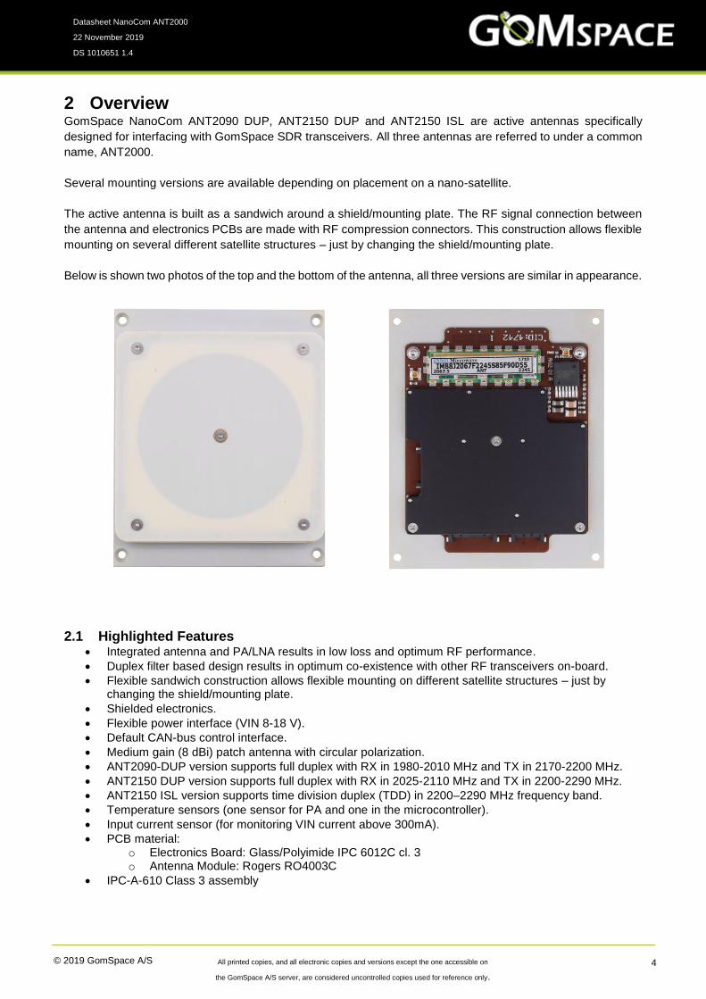
2 Overview GomSpace NanoCom ANT2090 DUP, ANT2150 DUP and ANT2150 ISL are active antennas specifically
designed for interfacing with GomSpace SDR transceivers. All three antennas are referred to under a common
name, ANT2000.
Several mounting versions are available depending on placement on a nano-satellite.
The active antenna is built as a sandwich around a shield/mounting plate. The RF signal connection between
the antenna and electronics PCBs are made with RF compression connectors. This construction allows flexible
mounting on several different satellite structures – just by changing the shield/mounting plate.
Below is shown two photos of the top and the bottom of the antenna, all three versions are similar in appearance.
2.1 Highlighted Features • Integrated antenna and PA/LNA results in low loss and optimum RF performance.
• Duplex filter based design results in optimum co-existence with other RF transceivers on-board.
• Flexible sandwich construction allows flexible mounting on different satellite structures – just by changing the shield/mounting plate.
• Shielded electronics.
• Flexible power interface (VIN 8-18 V).
• Default CAN-bus control interface.
• Medium gain (8 dBi) patch antenna with circular polarization.
• ANT2090-DUP version supports full duplex with RX in 1980-2010 MHz and TX in 2170-2200 MHz.
• ANT2150 DUP version supports full duplex with RX in 2025-2110 MHz and TX in 2200-2290 MHz.
• ANT2150 ISL version supports time division duplex (TDD) in 2200–2290 MHz frequency band.
• Temperature sensors (one sensor for PA and one in the microcontroller).
• Input current sensor (for monitoring VIN current above 300mA).
• PCB material: o Electronics Board: Glass/Polyimide IPC 6012C cl. 3 o Antenna Module: Rogers RO4003C
• IPC-A-610 Class 3 assembly

© 2019 GomSpace A/S All printed copies, and all electronic copies and versions except the one accessible on
the GomSpace A/S server, are considered uncontrolled copies used for reference only.
Datasheet NanoCom ANT2000
22 November 2019
DS 1010651 1.4
5
2.2 Block Diagram
2.3 Functional Description ANT2000 contain: a transmit power amplifier, a receive low noise amplifier, transmit/receive switch (ISL
version), and necessary support circuits.
The antenna section includes matching components and the RF compression connectors. Stated antenna gain
includes loss in matching circuit and in the RF connectors.
The transmitter chain includes a (pre) driver amplifier stage and a multistage balanced PA. Interstage SAW
filters reduce broadband noise and provides stage isolation.
The receiver chain contains two LNAs again with interstage SAW filters to protect following stages from out-of-
band interference.
All performance parameters for the electronics board and for the antenna module are given at the reference
plane.
2.3.1 ISL Version
This front-end uses the same frequency band for RX and TX, which allows two ISL radio board to communicate
using time division duplex.

© 2019 GomSpace A/S All printed copies, and all electronic copies and versions except the one accessible on
the GomSpace A/S server, are considered uncontrolled copies used for reference only.
Datasheet NanoCom ANT2000
22 November 2019
DS 1010651 1.4
6
The ISL front-end has a TX/RX switch and uses a bandpass filter (half of duplex-filter) that reduces transmitter
noise (broadband) significantly. During production/checkout it can be configured if the antenna should use
RHCP or LHCP.
2.3.2 DUP Version
The DUP version is the same as the ISL version except for the TX/RX switch and the filters on the Receiver
chain. This version is available for two different frequency bands (see section 3.2).
2.4 Calibration and Setup During production check-out, several calibration values are stored in the board.
For the receiver calibration values describe the RX gain at 7 frequencies across the RX band. These values
can be used to implement a compensated RSSI function. (Antenna gain is not included). The RSSI values can
also be temperature compensated using stored calibration values for gain temperature dependency.
The transmitter calibration values are primarily used to setup the correct input power to reach a given output
power (compensated for frequency and temperature). One calibration value describes the input power detector
level for a -10 dBm center frequency carrier, which will allow the SDR platform to set this level independently of
cable loss. All other input levels should be set relative to the calibrated -10 dB level.
The PA has three predefined bias levels, which are optimized for 2 W, 1 W, and 0.5 W (se chapter 10.3). All
levels are setup for maximum -20 dBc adjacent channel power for a 500 ksymbol/s QPSK (RC 0.35) modulated
signal.

© 2019 GomSpace A/S All printed copies, and all electronic copies and versions except the one accessible on
the GomSpace A/S server, are considered uncontrolled copies used for reference only.
Datasheet NanoCom ANT2000
22 November 2019
DS 1010651 1.4
7
3 Versions When ordering the customer must make a choice of:
• PCB version – ANT2150 ISL, ANT2150-DUP or ANT2090-DUP
• Antenna polarization (ISL default LHCP and DUP default RHCP)
• Mounting plate - depends on where the antenna is to be mounted
• Profile height – a special low profile of the antenna is available for the ISL version
• CAN termination – whether the board shall be equipped with a 120ohm terminated resistor on its CAN interface
3.1 Inter Satellite Link (ISL) and Profile
ANT2150 ISL Unit
TX band 2200 - 2290 MHz
RX band 2200 - 2290 MHz
The ISL antenna module version comes with either a standard profile or a low profile. The low profile is intended
for type D mounting (see chapter 3.3).
3.2 Duplex (DUP) and Profile DUP comes in two versions.
ANT2150 DUP ANT2090 DUP Unit
TX band 2200 - 2290 2170 - 2200 MHz
RX band 2025 - 2120 1980 - 2010 MHz
The DUP is only available with the standard profile antenna.
3.3 Mounting Plate Four different mounting plates are available, depending on where the antenna is placed on a nano-satellite.
They are all 1.5 mm aluminum. The 3U is used as an example; the plates can also be mounted on 1U and 2U
nano-satellite.

© 2019 GomSpace A/S All printed copies, and all electronic copies and versions except the one accessible on
the GomSpace A/S server, are considered uncontrolled copies used for reference only.
Datasheet NanoCom ANT2000
22 November 2019
DS 1010651 1.4
8
Type A
Used in a 3U structure on the A-sides and on the 6U
structure A-sides.
Type B
Used in 3U structure on the B-sides.
Type C
Used in the top or bottom of a 3U structure and not
exceed the height of the structure rails.
Type D
Designed for use with the GomSpace NanoCom
ANT-6F. When equipped with a ISL with a low
profile antenna, the design is made so that the
overall height doesn’t exceed the height of the
structure rails, when ANT-6F mounted on the top
or bottom of a 6U structure. If used with a standard
profile antenna, precautions should be taken to
ensure the launch-pod can accommodate the extra
height.

© 2019 GomSpace A/S All printed copies, and all electronic copies and versions except the one accessible on
the GomSpace A/S server, are considered uncontrolled copies used for reference only.
Datasheet NanoCom ANT2000
22 November 2019
DS 1010651 1.4
9
4 Connector Pinout
4.1 Connector Location Top
● Temperature sensors T1 - PA
T2 - Internal IC
4.1.1 J102 - RX RF COAXIAL CONNECTOR
Molex SSMCX 73413-0040
Pin Name Description
1 RX RF Amplified received signal
2 GND
4.1.2 J300 - TX RF COAXIAL CONNECTOR
Molex SSMCX 73413-0040
Pin Name Description
1 TX RF Transmitter input signal
2 GND

© 2019 GomSpace A/S All printed copies, and all electronic copies and versions except the one accessible on
the GomSpace A/S server, are considered uncontrolled copies used for reference only.
Datasheet NanoCom ANT2000
22 November 2019
DS 1010651 1.4
10
4.1.3 J400 - Power Connector
Molex Pico-Lock 1.50 mm pitch 504050-0791
Pin Name Description
1 AABON External power control pin: Low < 0.4 V, High > 2.5 V (max 18V)
Low: Antenna is OFF
High: Antenna is ON (Antenna enters IDLE mode when AABON pin is asserted)
2 GND
3 GND
4 GND
5 VIN 8 – 18 V supply voltage, externally switchable by AABON
6 VIN 8 – 18 V supply voltage, externally switchable by AABON
7 VIN 8 – 18 V supply voltage, externally switchable by AABON
4.1.4 J401 - Control Connector
Molex Pico-Lock 1.50 mm pitch 504050-1091
Pin Name Description
1 GND
2 GND
3 I2C_SCL CSP I2C bus communication
4 I2C_SDA CSP I2C bus communication
5 CANL CSP CAN bus communication (Linear LTC2875 CAN transceiver used)
6 CANH CSP CAN bus communication (Linear LTC2875 CAN transceiver used)
7 GND
8 TXEN_EX Select TX mode in manual duplex mode
9 TXON_EX Power on TX circuit
10 RXON_EX Power on RX circuit
4.1.5 J402 - Debug
Molex Pico-Lock 1.50 mm pitch 504050-0691
Pin Name Description
1 GND
2 UART RX GOSH serial communication
3 UART TX GOSH serial communication
4 SWCLK Firmware upload/debug
5 SWDIO Firmware upload/debug
6 RESETn Firmware upload/debug

© 2019 GomSpace A/S All printed copies, and all electronic copies and versions except the one accessible on
the GomSpace A/S server, are considered uncontrolled copies used for reference only.
Datasheet NanoCom ANT2000
22 November 2019
DS 1010651 1.4
11
5 Data Interface ANT2000 use the CubeSat Space Protocol (CSP) to transfer data to and from CSP nodes on-board the main
system bus. CSP is a routed network protocol that can be used to transmit data packets between individual
subsystems on the satellite bus and between the satellite and ground station. For more information about CSP
please read the documentation on libcsp.org and on Wikipedia:
http://en.wikipedia.org/wiki/Cubesat_Space_Protocol
It’s possible to control the board via CAN (default) or I2C.
6 Debug Interface The debug interface is a USART that uses the GomSpace Shell (GOSH) to present a console-like interface to
the user. GOSH is a general feature present on all GomSpace products.
The console can be used during checkout and satellite integration of the antennas to send commands and
inspect/set parameters.
7 Absolute Maximum Ratings Stresses above those listed under Absolute Maximum Ratings may cause permanent damage to the antennas.
Exposure to absolute maximum rating conditions for extended periods may affect the reliability.
Symbol Description Min. Max. Unit
VIN Input Supply voltage 8.0 18.0 V
PIN Supply power draw - 11 W
Pin Absolute maximum input power at TX
and RX ports
5 dBm
Tamb Operating Temperature -40 85 °C
Tstg Storage Temperature -40 85 °C
8 Electrical Characteristics
Symbol Description Min. Max. Unit
Psup_off Supply power, OFF - 1.8 mW
Psup_idle Supply power, IDLE - 200 mW
Psup_rx Supply power, RX mode - 800 mW
Psup_tx Supply power, TX STANDBY - 600 mW
Psup_tx Supply power, TX ACTIVE - 10700 mW
9 Physical Characteristics
Description Value Unit
Mass (approximate – depends on mounting etc) ~ 110 g
Size (see chapter 12) 98 x 98 x 20.1 mm

© 2019 GomSpace A/S All printed copies, and all electronic copies and versions except the one accessible on
the GomSpace A/S server, are considered uncontrolled copies used for reference only.
Datasheet NanoCom ANT2000
22 November 2019
DS 1010651 1.4
12
10 RF Performance Characteristics
10.1 Receiver ISL
Symbol Description Min. Max. Unit
Gain,rx RX Avg. Gain, 25°C 35 39 dB
Gain ripple 25°C -3 3 dB
Gain ripple -40°C to 85°C -3 -3 dB
NF,rx RX Noise Figure, 25°C 2.5 (typ) 2.8 dB
RX Noise Figure, -40°C to 85°C 3.5 dB
Freq, rx RX frequency band 2200 2290 MHz
10.2 Receiver DUP
Symbol Description Min. Max. Unit
Gain,rx RX Avg. Gain, 25°C 39 45 dB
Gain ripple 25°C -4 4 dB
Gain ripple -40°C to 85°C -5 -5 dB
NF,rx RX Noise Figure, 25°C 2.0 (typ) 2.5 dB
RX Noise Figure, -40°C to 85°C 3.0 dB
Freq, rx RX band (ANT-2150-DUP) 2025 2110 MHz
RX band (ANT-2090-DUP) 1980 2010 MHz
10.3 Transmitter
Symbol Description Min. Max. Unit
Pow.level 2 Pout 32.0 (typ) dBm
Pout ripple -1.5 1 dB
Pin -13 -3 dBm
DC Power (typical) (Vin 10V) 8.9 10.0 W
Pow.level 1 Pout 29.8 (typ) dBm
Pout ripple -2 1 dB
Pin -16 -6 dBm
DC Power (typical) (Vin 10V) 6.1 7.1 W
Pow.level 0 Pout 26.8 (typ) dBm
Pout ripple -2 1 dB
Pin -19 -9 dBm
DC Power (typical) (Vin 10V) 4.0 4.5 W
Pin,thr Threshold for input detector – rising -33 -24 dBm
Pin,thr,hys Hysteresis for input power det. 2 dB
Pout,min Min. output power for automatic TX 8 16 dBm
Dup,Act Auto duplex activation time 140 μSec
© 2019 GomSpace A/S All printed copies, and all electronic copies and versions except the one accessible on
the GomSpace A/S server, are considered uncontrolled copies used for reference only.
Datasheet NanoCom ANT2000
22 November 2019
DS 1010651 1.4
13
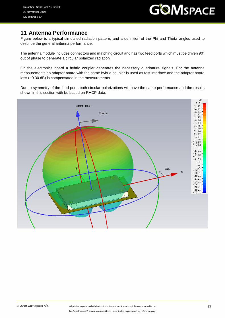
11 Antenna Performance Figure below is a typical simulated radiation pattern, and a definition of the Phi and Theta angles used to
describe the general antenna performance.
The antenna module includes connectors and matching circuit and has two feed ports which must be driven 90°
out of phase to generate a circular polarized radiation.
On the electronics board a hybrid coupler generates the necessary quadrature signals. For the antenna
measurements an adaptor board with the same hybrid coupler is used as test interface and the adaptor board
loss (~0.30 dB) is compensated in the measurements.
Due to symmetry of the feed ports both circular polarizations will have the same performance and the results
shown in this section with be based on RHCP data.
© 2019 GomSpace A/S All printed copies, and all electronic copies and versions except the one accessible on
the GomSpace A/S server, are considered uncontrolled copies used for reference only.
Datasheet NanoCom ANT2000
22 November 2019
DS 1010651 1.4
14
11.1 Standard Profile
11.1.1 Antenna Gain
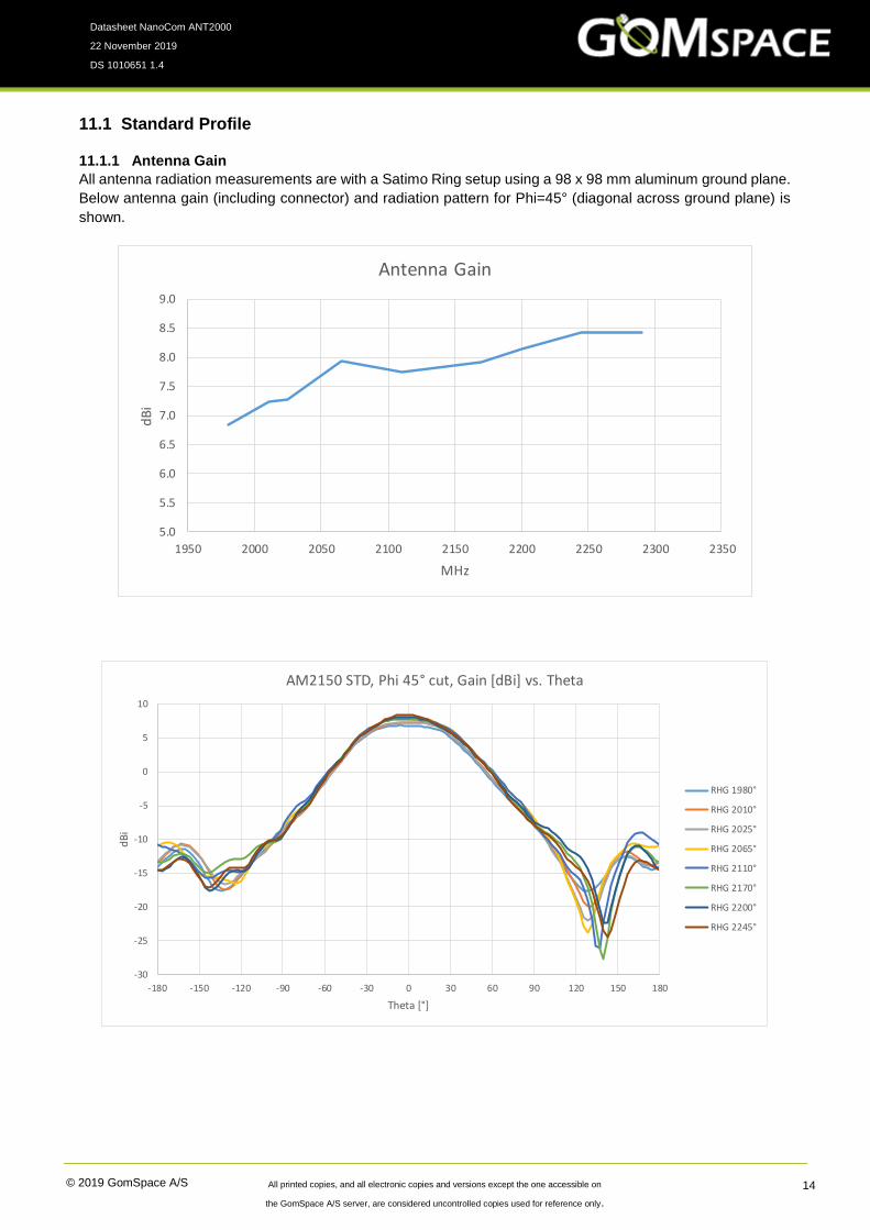
All antenna radiation measurements are with a Satimo Ring setup using a 98 x 98 mm aluminum ground plane.
Below antenna gain (including connector) and radiation pattern for Phi=45° (diagonal across ground plane) is
shown.
5.0
5.5
6.0
6.5
7.0
7.5
8.0
8.5
9.0
1950 2000 2050 2100 2150 2200 2250 2300 2350
dB
i
MHz
Antenna Gain
-30
-25
-20
-15
-10
-5
0
5
10
-180 -150 -120 -90 -60 -30 0 30 60 90 120 150 180
dB
i
Theta [°]
AM2150 STD, Phi 45° cut, Gain [dBi] vs. Theta
RHG 1980°
RHG 2010°
RHG 2025°
RHG 2065°
RHG 2110°
RHG 2170°
RHG 2200°
RHG 2245°

© 2019 GomSpace A/S All printed copies, and all electronic copies and versions except the one accessible on
the GomSpace A/S server, are considered uncontrolled copies used for reference only.
Datasheet NanoCom ANT2000
22 November 2019
DS 1010651 1.4
15
11.1.2 Axial Ratio
All three antennas are circular polarized, and product polarization is determined by the electronics PCB.
Below the maximum axial ratio for -40...40° elevation is shown as a function of frequency, and the axial ratio as
a function of Theta for a Phi angle of 45°.
As seen the axial ratio is quite good within the halfpower beamwidth.
0.0
0.5
1.0
1.5
2.0
2.5
3.0
3.5
4.0
4.5
1950 2000 2050 2100 2150 2200 2250 2300 2350
dB
MHz
Antenna Axial Ratio (max for Theta ±40°)
0.0
5.0
10.0
15.0
20.0
25.0
30.0
-180 -150 -120 -90 -60 -30 0 30 60 90 120 150 180
dB
Theta [°]
AM2150 STD, Phi 45° cut, Axial Ratio [dB] vs. Theta
AR 1980°
AR 2010°
AR 2025°
AR 2065°
AR 2110°
AR 2170°
AR 2200°
AR 2245°
© 2019 GomSpace A/S All printed copies, and all electronic copies and versions except the one accessible on
the GomSpace A/S server, are considered uncontrolled copies used for reference only.
Datasheet NanoCom ANT2000
22 November 2019
DS 1010651 1.4
16
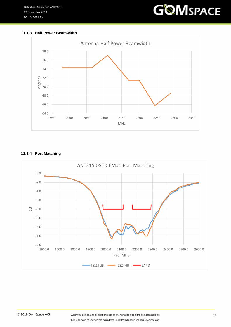
11.1.3 Half Power Beamwidth
11.1.4 Port Matching
64.0
66.0
68.0
70.0
72.0
74.0
76.0
78.0
1950 2000 2050 2100 2150 2200 2250 2300 2350
deg
rees
MHz
Antenna Half Power Beamwidth
-16.0
-14.0
-12.0
-10.0
-8.0
-6.0
-4.0
-2.0
0.0
1600.0 1700.0 1800.0 1900.0 2000.0 2100.0 2200.0 2300.0 2400.0 2500.0 2600.0
dB
Freq [MHz]
ANT2150-STD EM#1 Port Matching
|S11| dB |S22| dB BAND

© 2019 GomSpace A/S All printed copies, and all electronic copies and versions except the one accessible on
the GomSpace A/S server, are considered uncontrolled copies used for reference only.
Datasheet NanoCom ANT2000
22 November 2019
DS 1010651 1.4
17
11.2 Low Profile Only the ANT2150 ISL in the 2200-2290 MHz frequency band can use the low profile antenna.
The Half power beamwidth and the axial ration is virtually the same as for the standard antenna.
11.2.1 Antenna Gain
Performance within this band is marginally lower than the standard antenna primarily due to matching losses.
Below the gain [dBi] is shown in comparison with the standard profile antenna.
11.2.2 Port Matching
The matching of the ports is significantly more narrowband than the standard antenna as shown below.
5.0
5.5
6.0
6.5
7.0
7.5
8.0
8.5
9.0
1950 2000 2050 2100 2150 2200 2250 2300 2350
dB
i
MHz
Antenna Gain
RH STD
RH LP
-45
-40
-35
-30
-25
-20
-15
-10
-5
0
1600 1700 1800 1900 2000 2100 2200 2300 2400 2500 2600
dB
Freq [MHz]
ANT2150-LP EM#1 Port Matching
|S11| dB |S22| dB BAND
© 2019 GomSpace A/S All printed copies, and all electronic copies and versions except the one accessible on
the GomSpace A/S server, are considered uncontrolled copies used for reference only.
Datasheet NanoCom ANT2000
22 November 2019
DS 1010651 1.4
18
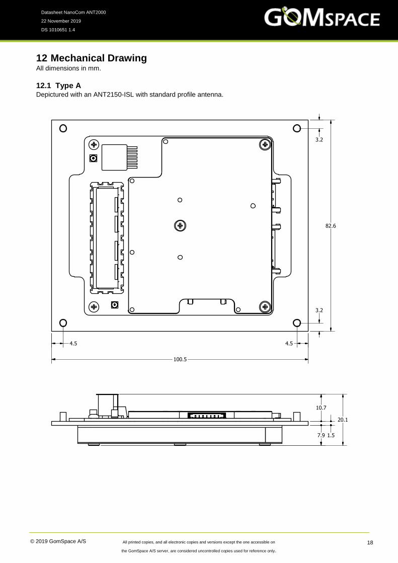
12 Mechanical Drawing All dimensions in mm.
12.1 Type A Depictured with an ANT2150-ISL with standard profile antenna.
1
1
2
2
3
3
4
4
A A
B B
C C
D D
SHEET 1 OF 1
DRAWN
CHECKED
QA
MFG
APPROVED
jal 03-02-2017
DWG NO
FullBandX
TITLE
SIZE
CSCALE
REV
82.6
3.2
3.2
4.54.5
100.5
7.9 1.5
10.7
20.1
© 2019 GomSpace A/S All printed copies, and all electronic copies and versions except the one accessible on
the GomSpace A/S server, are considered uncontrolled copies used for reference only.
Datasheet NanoCom ANT2000
22 November 2019
DS 1010651 1.4
19
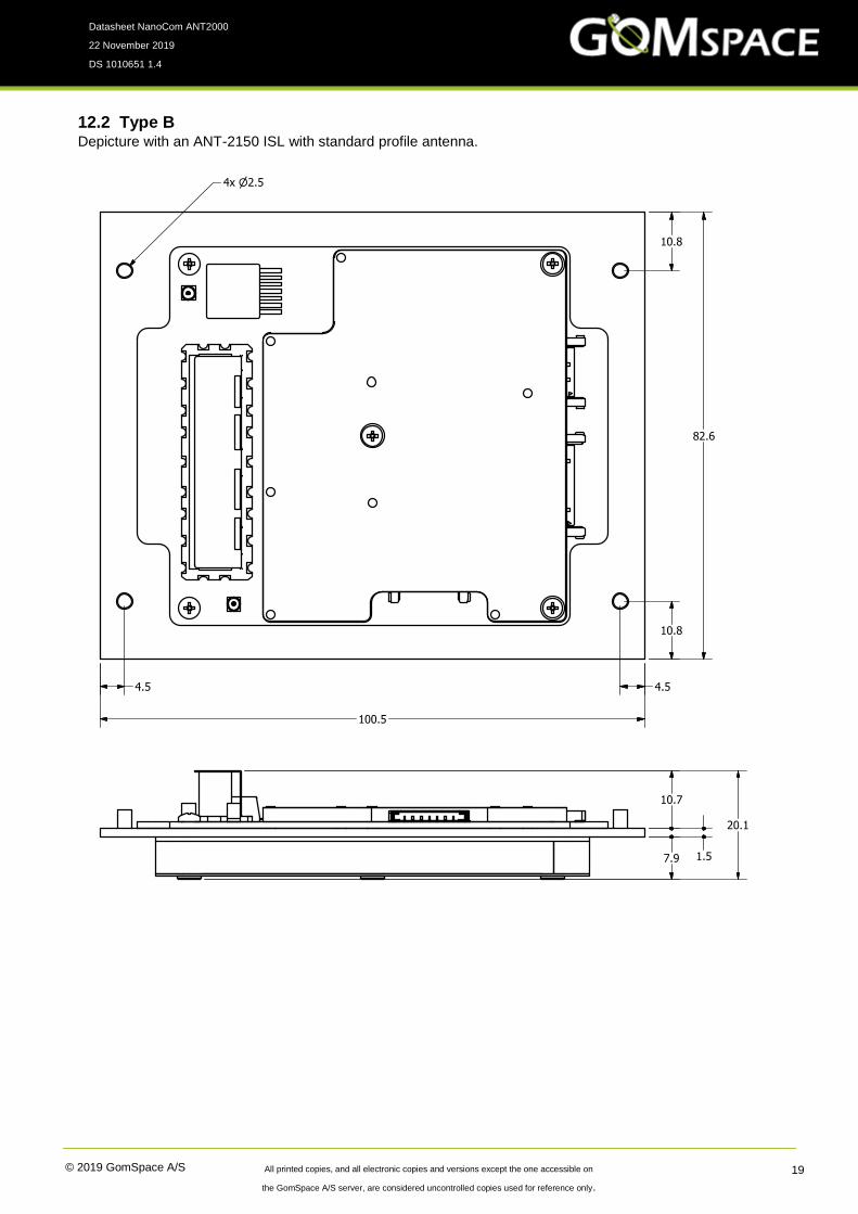
12.2 Type B Depicture with an ANT-2150 ISL with standard profile antenna.

© 2019 GomSpace A/S All printed copies, and all electronic copies and versions except the one accessible on
the GomSpace A/S server, are considered uncontrolled copies used for reference only.
Datasheet NanoCom ANT2000
22 November 2019
DS 1010651 1.4
20
12.3 Type C Depictured with an ANT-2150 ISL with standard profile antenna.

© 2019 GomSpace A/S All printed copies, and all electronic copies and versions except the one accessible on
the GomSpace A/S server, are considered uncontrolled copies used for reference only.
Datasheet NanoCom ANT2000
22 November 2019
DS 1010651 1.4
21
12.4 Type D Depictured with an ANT2150-ISL with Low profile antenna.

© 2019 GomSpace A/S All printed copies, and all electronic copies and versions except the one accessible on
the GomSpace A/S server, are considered uncontrolled copies used for reference only.
Datasheet NanoCom ANT2000
22 November 2019
DS 1010651 1.4
22
13 Disclaimer The information in this document is subject to change without notice and should not be construed as a
commitment by GomSpace. GomSpace assumes no responsibility for any errors that may appear in this
document.
In no event shall GomSpace be liable for incidental or consequential damages arising from use of this document
or the software and hardware described in this document.