Embed Size (px)
DESCRIPTION
ansys multiphysics tutorials
Citation preview

System Coupling 14.0 – Two-way FSI with ANSYS FLUENT and ANSYS Mechanical
© 2011 ANSYS, Inc. May 15, 20121
ANSYS Regional Conference

Fluid-Structure Interaction Applications
Floating thin film
© 2011 ANSYS, Inc. May 15, 20122
Fluid-structure interaction problems encompass a wide range of
applications in many different industries.
Aerospace, automotive, power generation, biomedical, etc.
Mitral valveWind Turbine

• The solution to two-way fluid-structure interaction
requires co-simulation between computational fluid
dynamics and structural mechanics.
• Applications such as air foil flutter, flow induced
vibration from wind loading, membrane valves, pumps,
elastic artery modeling and fuel tank sloshing require a
Fluid-Structure Interaction
© 2011 ANSYS, Inc. May 15, 20123
elastic artery modeling and fuel tank sloshing require a
two-way fluid-structure interaction solution to
accurately predict the behavior of the design.

• Facilitates simulations that require tightly integrated
couplings of analysis systems in the ANSYS portfolio
• Extensible architecture for range of coupling scenarios
(one-, two- & n-way, static data, co-simulation…)
• ANSYS Workbench user environment and workflow
• Standard execution management and data interfaces
System Coupling 14.0
© 2011 ANSYS, Inc. May 15, 20124
• Standard execution management and data interfaces

• Two-way surface force/displacement coupling with
ANSYS Fluent and ANSYS Mechanical
– Steady/static and transient two-way FSI
• Workbench based setup and execution
– Windows and Linux
System Coupling 14.0 – A Broad Range of Features
© 2011 ANSYS, Inc. May 15, 20125
• Execution from command line outside of Workbench
including cross-platform execution
• Integrated post-processing with ANSYS CFD-Post
• Parallel processing for both CFD and structural
solutions with ANSYS HPC
– RSM currently not supported
• Restarts for fluid-structure interaction
• Parameterization, design exploration and optimization

System Coupling Schematic Setup
© 2011 ANSYS, Inc. May 15, 20126

• Solution update can ONLY be done via System Coupling
• System Coupling ensures that the time duration and
time step settings are consistent across all participant
solvers
System Coupling Controls the Participant Solvers for Transient and Steady/Static Solutions
© 2011 ANSYS, Inc. May 15, 20127

Two-way FSI setup: important steps
© 2011 ANSYS, Inc. May 15, 20128
Pressure = 100 pa
for 0.5 sec
Total time duration = 10 sec

Setup Transient Structural Model
© 2011 ANSYS, Inc. May 15, 20129
Setup transient structural
solution, structural
boundary conditions and
Fluid Solid Interface

Setup Fluid Flow (FLUENT) Model
© 2011 ANSYS, Inc. May 15, 201210
Setup transient fluid solution, fluid
boundary conditions and specify
System Coupling Dynamic Mesh
Zone for fluid-structure interaction
motion

• System Coupling motion
identifies zones that may
participate in System Coupling
• Allows user-defined motion to be
combined with System Coupling
motion
System Coupling Motion Type
© 2011 ANSYS, Inc. May 15, 201211
motion
• Defaults to stationary motion
type when not connected to
System Coupling

• State of System Coupling setup cell will be
– Upstream data is now available for SC Setup
Update Setup Cells for Transient Structural and Fluid Flow (FLUENT)
© 2011 ANSYS, Inc. May 15, 201212

System Coupling Setup GUI
Chart
MonitorsOutline
© 2011 ANSYS, Inc. May 15, 201213
Solution Information
Text MonitorsDetails

• Coupling End Time
• Coupling Step Size
• Minimum Number of Iterations
per Coupling Step
• Maximum Number of Iterations
per Coupling Step
System Coupling Analysis Settings
© 2011 ANSYS, Inc. May 15, 201214
per Coupling Step

• Region and variable information
is generated automatically via
Update when analysis systems
are first connected to System
Coupling
• For FLUENT, all regions of type
System Coupling Participants are Transient Structural and Fluid Flow (FLUENT)
© 2011 ANSYS, Inc. May 15, 201215
• For FLUENT, all regions of type
Wall are shown in SC Setup
• For Mechanical, all regions of
type Fluid Solid Interface are
shown in SC Setup

• Use Ctrl key to select a FLUENT
and Mechanical region pair and
select Create Data Transfer from
right-click pop-up menu
• Automatically fills in the details
for the data transfer region
Recommended Way to Create Data Transfer Regions
© 2011 ANSYS, Inc. May 15, 201216
for the data transfer region
• Data transfers can be one-way
(i.e. only transfer force or only
transfer displacement) or two-
way

Create Data Transfers
© 2011 ANSYS, Inc. May 15, 201217

• Participant
• Region
• Variable
• Transfer At
– Start of Iteration only
Data Transfer Defines the Details for the Source, Target and Data Transfer Controls
© 2011 ANSYS, Inc. May 15, 201218
– Start of Iteration only
• Under Relaxation Factor
• Convergence Target

• Co-Simulation Sequence
– Transient or Static Structural will
always be first in the co-simulation
sequence
• Debug Output
– Different levels of debug output for
Execution Control
© 2011 ANSYS, Inc. May 15, 201219
– Different levels of debug output for
analysis and data transfers
• Intermediate Results File Output
– Controls the intervals for writing
restart file information

Executing System Coupling
© 2011 ANSYS, Inc. May 15, 201220

• From schematic select Update using right-click menu
on System Coupling solution cell
• Solution progress (% complete) can be monitored using
View Progress menu
Alternative Method for Executing System Coupling
© 2011 ANSYS, Inc. May 15, 201221
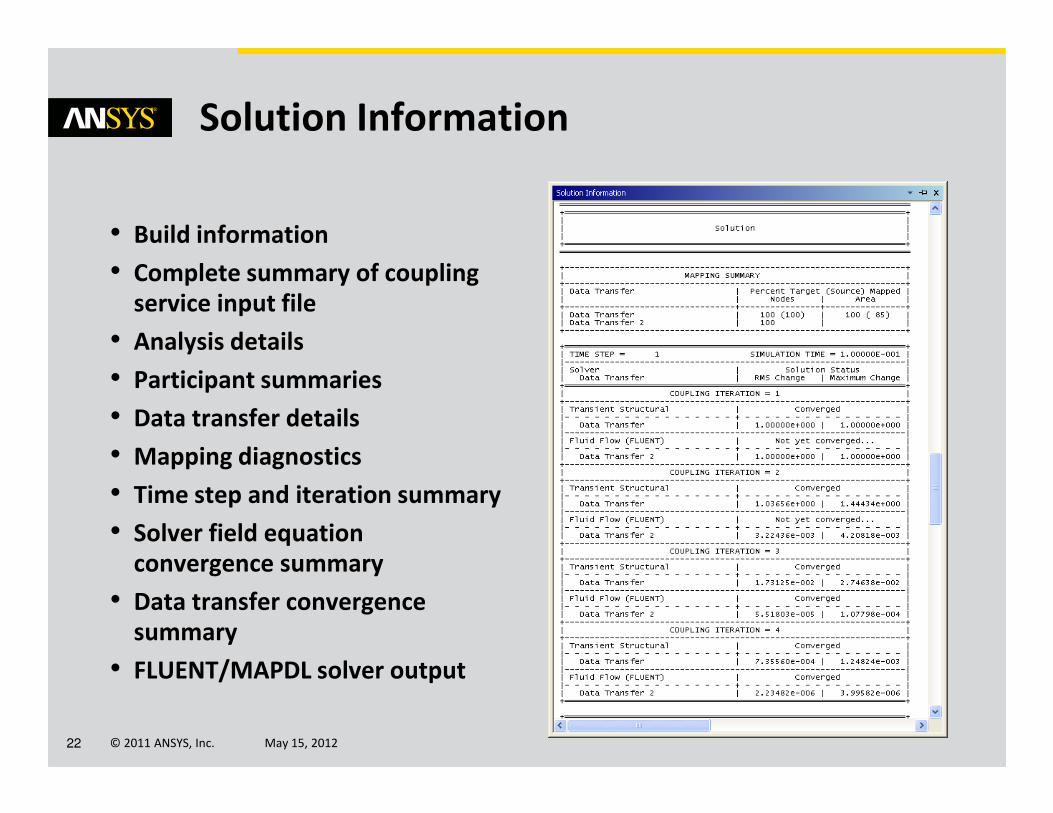
• Build information
• Complete summary of coupling
service input file
• Analysis details
• Participant summaries
• Data transfer details
Solution Information
© 2011 ANSYS, Inc. May 15, 201222
• Data transfer details
• Mapping diagnostics
• Time step and iteration summary
• Solver field equation
convergence summary
• Data transfer convergence
summary
• FLUENT/MAPDL solver output

Chart Monitors
© 2011 ANSYS, Inc. May 15, 201223
Default chart monitors
show convergence
history for all data
transfers.
X-axis can be
coupling time,
step or
iteration.

• Add charts by selecting Create Convergence Chart
• Variables can be added or removed from charts
– Data transfers, CFD and structural convergence
norms
• Chart properties are editable in same manner as other
charts within ANSYS Workbench
Adding Charts and Variables
© 2011 ANSYS, Inc. May 15, 201224
charts within ANSYS Workbench

• Transient Structural or Fluid Flow (FLUENT) Results cell
for solver-specific post-processing
• Add a Results System (ANSYS CFD-Post) for unified
post-processing of structural and fluid results
Post Processing System Coupling
© 2011 ANSYS, Inc. May 15, 201225

• Oscillating Plate Verification
– Excellent correlation between
System Coupling, published
data and MFX solver
Post Processing System Coupling
© 2011 ANSYS, Inc. May 15, 201226

System Coupling – Examples
© 2011 ANSYS, Inc. May 15, 201227
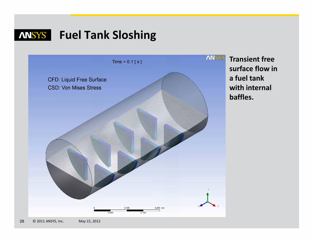
Fuel Tank Sloshing
Transient free
surface flow in
a fuel tank
with internal
baffles.
© 2011 ANSYS, Inc. May 15, 201228

Mitral Valve
Transient blood
flow through a
three leaf mitral
valve, non-
Newtonian fluid
and anisotropic
hyperelastic
tissue. Solution
© 2011 ANSYS, Inc. May 15, 201229
tissue. Solution
includes re-
meshing of the
fluid domain and
nonlinear
contact.

Reed Valve
Transient
response of
reed valve
opening and
closing.
Solution
includes re-
© 2011 ANSYS, Inc. May 15, 201230
includes re-
meshing of the
fluid domain,
large
deformations
and nonlinear
contact.

Vibrating Rod
Transient
response of
vibrating rod
including
vortex
shedding.
© 2011 ANSYS, Inc. May 15, 201231

Deformation of a Leakage Path
Steady state
solution for a
narrow
representative
leakage path in a
fuel injector
assembly
clearance gap.
© 2011 ANSYS, Inc. May 15, 201232
clearance gap.

Questions and Answers
© 2011 ANSYS, Inc. May 15, 201233