Embed Size (px)
Citation preview
Cisco NetworkingAcademy Program:
Lab CompanionVolume I
ANSWER KEY
Authorized Lab Companion for the Cisco Networking Academy Program
ciscopress.com
Author, Jim Lorenz
Series Editor, Vito Amato

- 1 -
Cisco Networking Academy Program: Lab Companion, Volume IISBN: 1-58713-022-X
Copyright © 2000 Cisco Systems
Cisco Labs–Semester 1–Networking FundamentalsLAB 1.1.1–PC HARDWARE–ANSWERS
Step 1
1. What is the manufacturer and model number of this computer?Manufacturer XYZ Company
Model Number XYZ model
2. List at least 8 major internal components inside the system unit.Component Name Manufacturer/Description/Characteristics
Power Supply 200 watt
Motherboard XYXCPU type Pentium II (See step 5)RAM 64 MB (See step 5)Hard Drive IDE 2 GBCD-ROM drive 24xFloppy Drive 1.44 MB
Parallel port 25-pin EPPSerial port 9-pin
Video Card XYZ companySound Card XYZ companyNetwork Interface Card (NIC) XYX companyOther
3. What are the major external components of the PC, including the peripherals?Component Name Manufacturer/Description/Characteristics
System unit CompaqMonitor Compaq 15" SVGAKeyboard 101 Key enhancedMouse MicrosoftPrinter HP XYZOther
Step 2
1. Observe the boot process.
a. Did the Windows operating system boot OK? Yesb. Could you see how much memory there was as the system was booting? Yes, 64 MB (Megabytes)
Step 3
1. a. What is the Central Processing Unit? Pentium IIb. How much RAM is installed? 64 MB

- 2 -
Cisco Networking Academy Program: Lab Companion, Volume IISBN: 1-58713-022-X
Copyright © 2000 Cisco Systems
Cisco Labs–Semester 1–Networking FundamentalsLAB 1.1.4–NIC INSTALLATION–ANSWERS
1. Turn off your computer and unplug the power cable. Use a static mat and wrist strap toground yourself.
2. Remove the cover from the computer. Remove the dust plate from the computer case for theempty PCI or ISA expansion slot in which you plan to install the NIC card.
3. Remove the network card from the anti-static bag. Handle the top corners of the network cardwith both hands. Align the tabs of the network card with the slot and gently rock the cardfront to rear to insert it into the expansion slot. Finally, secure the card to the case with ascrew.
4. Plug a straight-through wired network patch cable into the back of the NIC. The cable shouldconnect to a hub or switch with other PCs in a workgroup. The green link light on the back ofthe NIC should come on when the PC is restarted, indicating a good connection with the hubor switch.
5. Restart the computer. The Windows 95/98 setup hardware detection will automaticallydetermine the adapter driver for your network card. Windows may ask you to supply yourcomputer name and workgroup name. Select a computer name for your PC, and use a specificworkgroup name provided by your lab instructor.
6. Double-click the Network Neighborhood icon on the desktop. If you find other computernames displayed in the window, the network card is working properly. If you do not findother computer names, then Windows might have installed an incorrect driver for yournetwork card. If so, you will need to perform the following steps to add an adapter driver:
1. Click the Start button, select Settings, then select Control Panel.2. Double-click the Network icon. A network dialog box will appear.3. Click the Add button. Select adapter and click on the Add button again.4. Click the Have Disk button. Insert the network card's driver disk into the floppy drive.
Click OK. The Windows setup will install the driver.5. Windows might ask you to reboot your system. After you restart the computer, follow the
instructions in the beginning of this exercise to check whether your network card isworking properly.
Reflection:Write in your journal the steps that you used to install a network card. Also write what precautionsyou took and why they were important.
Be sure to write in your journal about the proper care that must be taken when working on the insideof PCs (for example, anti-static precautions, changing one thing at a time, working with the poweroff, using the proper tools). Also record any problems that might have occurred, such as incorrectdrivers.

- 3 -
Cisco Networking Academy Program: Lab Companion, Volume IISBN: 1-58713-022-X
Copyright © 2000 Cisco Systems

- 4 -
Cisco Networking Academy Program: Lab Companion, Volume IISBN: 1-58713-022-X
Copyright © 2000 Cisco Systems
Cisco Labs–Semester 1–Networking FundamentalsLAB 1.2.1.1–TCP/IP NETWORK SETTINGS–ANSWERS
Step 2
1. Record your findings in the table below.Computer (NetBIOS) Name W1-005NT Domain Name Domain1Network Client Type Client for Microsoft networks (and/or Novell Client)NIC installed (driver name) 3-COM Fast Etherlink 10/100 (or other NIC mfg)1st Protocol installed TCP/IP2nd Protocol installed IPX/SPX-compatible protocol (if there are Novell
servers)Other network componentsOther network components
Step 3
1. Record your findings in the table below.
- 5 -
Cisco Networking Academy Program: Lab Companion, Volume IISBN: 1-58713-022-X
Copyright © 2000 Cisco Systems
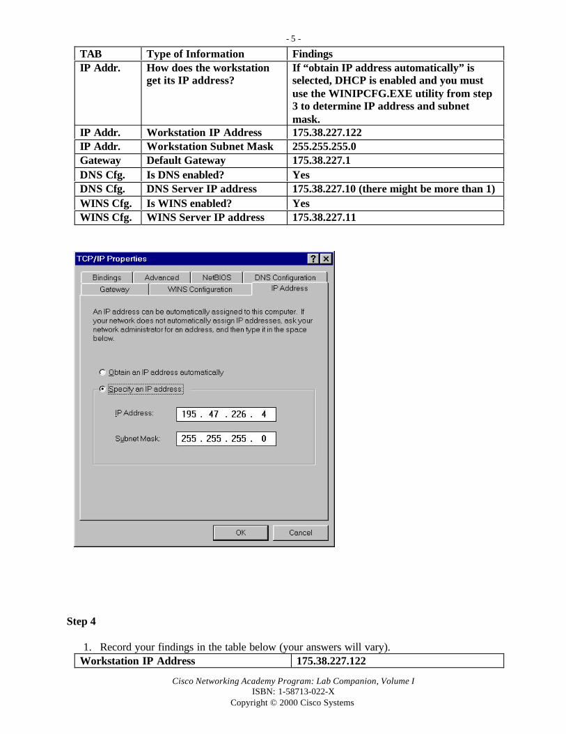
TAB Type of Information FindingsIP Addr. How does the workstation
get its IP address?If “obtain IP address automatically” isselected, DHCP is enabled and you mustuse the WINIPCFG.EXE utility from step3 to determine IP address and subnetmask.
IP Addr. Workstation IP Address 175.38.227.122IP Addr. Workstation Subnet Mask 255.255.255.0Gateway Default Gateway 175.38.227.1DNS Cfg. Is DNS enabled? YesDNS Cfg. DNS Server IP address 175.38.227.10 (there might be more than 1)WINS Cfg. Is WINS enabled? YesWINS Cfg. WINS Server IP address 175.38.227.11
Step 4
1. Record your findings in the table below (your answers will vary).Workstation IP Address 175.38.227.122

- 6 -
Cisco Networking Academy Program: Lab Companion, Volume IISBN: 1-58713-022-X
Copyright © 2000 Cisco Systems
Workstation Subnet Mask 255.255.255.0Workstation MAC Address 00-08-C7-5B-A6-ABDefault Gateway 175.38.227.1DHCP Server 175.38.227.15DNS Server IP address 175.38.227.10 (can be more than 1)WINS Server IP address 175.38.227.11 (primary and secondary)
Step 5
1. Record your findings in the table below.Network Adapter (NIC) Manufacturer Compaq NC3120 Fast Ethernet NICIs the Network Adapter working properly? YesDate of the Driver 4-23-99List one of the driver files E100BNT.SYS

- 7 -
Cisco Networking Academy Program: Lab Companion, Volume IISBN: 1-58713-022-X
Copyright © 2000 Cisco Systems
Cisco Labs–Semester 1–Networking FundamentalsLAB 1.2.1.2–PC SOFTWARE–ANSWERS
Step 1
1. What is the PC manufacturer and model? Compaq Desktop
Step 2
1. What operating system (OS) and version is the computer running? Windows 98 SecondEdition 400.10.2222A
Step 3
1. How would you access the CMOS setup to change settings? Press F10 when the message isdisplayed at boot-up
2. Who is the BIOS manufacturer? XYZ BIOS v4.56
Step 4
1. What is the browser software and version? Netscape Navigator version 4.6 or InternetExplorer version 5.0.
2. Is the QuickTime plug-in on this computer? Yes
3. Is the ShockWave plug-in on this computer? Yes
4. Does the sound work when playing the videos? Yes
Step 5
1. Record the settings on your computer below:Screen area (resolution) 800 x 600 (super VGA)Colors 256

- 8 -
Cisco Networking Academy Program: Lab Companion, Volume IISBN: 1-58713-022-X
Copyright © 2000 Cisco Systems
Cisco Labs–Semester 1–Networking FundamentalsLAB 1.2.2–WEB BROWSER LITERACY–ANSWERS
1. Install Netscape or Internet Explorer on your computer (if it has not already been done).
2. If you are on a LAN, start the web browser (either Netscape or Internet Explorer). If you areusing a modem to make the connection, you must dial your ISP before you can start your webbrowser.
3. What version of Netscape or Internet Explorer are you using? Netscape 4.6 or InternetExplorer 5.0 (Click the Help menu, then About to find out the exact product name andversion.)
4. After you start your browser, click and highlight the Location field (with Netscape) orAddress field (with Internet Explorer). Press the Delete key to delete the current address.
5. When your Location or Address field is empty, type in www.cisco.com to get to the Ciscoweb site. This is how you can navigate from one site to another on the World Wide Web(WWW).
6. Load a new page (type in a new location, for example, www.nba.com). Notice the status onthe bottom bar of your browser. What do you see? You should see the status of the web pagethat is loading (i.e., percentage done; contacting host; starting Java; and so on).
7. Each of the buttons on top of your browser has a function. Click the Back button. What did itdo? Takes you back to the Cisco web site or the previous web site you were at.
8. Click the Forward button. Does it take you to the NBA web site? Yes
9. Try clicking on the Reload or Refresh button. What do you think they do? They reloadeverything, which prevents your browser from loading old pages from its cache.
10. Type in a new web site address and click the Stop button. What happens? It will stopeverything from loading.
11. Enter the URL for a search engine such as www.metacrawler.com. Search for the wordBROWSER. What was the result? Showed search results and several possible web sites whereinformation on browsers can be obtained, including download sites.
12. Enter the URL for www.webopedia.com. Enter the keyword BROWSER. What was theresult? A brief definition of a browser was displayed. What other hyperlinks were available?Links to many other web sites, including Internet Explorer and Netscape Navigator wereavailable. The latest version of these browsers can be downloaded from the sites.

- 9 -
Cisco Networking Academy Program: Lab Companion, Volume IISBN: 1-58713-022-X
Copyright © 2000 Cisco Systems
Reflection Questions:1. Identify a way in which you can navigate from one site to another. Type in a web site that you
want to go to in the location or address field of your browser.
2. If you see the same graphics or text the next time you go to the NBA site, what should you do toensure that you could look at updated news? Press the Refresh or Reload button.

- 10 -
Cisco Networking Academy Program: Lab Companion, Volume IISBN: 1-58713-022-X
Copyright © 2000 Cisco Systems
Cisco Labs–Semester 1–Networking FundamentalsLAB 1.2.3–BASIC TROUBLESHOOTING–ANSWERS
The following are some of the potential problems that can be introduced with this lab.
COMMON PC HARDWARE- AND SOFTWARE-RELATED PROBLEMS
ProblemNumber
Category Symptoms Problem Description Solution
1 PCHardware
Monitor doesnot displayanything
Power corddisconnected at walloutlet
Plug monitor into outlet
2 PCHardware
Monitor doesnot displayanything
Power corddisconnected at monitor
Verify that it is plugged solidlyinto the monitor
3 PCHardware
Monitor doesnot displayanything
Video card damaged Open computer and replacewith working card
4 PCHardware
Monitor doesnot displayanything
Monitor video outputnot connected tocomputer
Verify that the cable isconnected to the PC system unitvideo DB15 adapter
5 PCHardware
Monitor doesnot displayanything
Brightness or contrastadjustment needs
Adjust brightness and/orcontrast accordingly
6 PCHardware
Can’t usemouse orkeyboard
Mouse or keyboarddisconnected
Verify they are pluggedsecurely into the correct portson the back of the PC
7 PCHardware
Can’t hearvideos
Speakers not plugged in Connect speaker to sound card
8 PCSoftware
Can’t hearvideos
Multimedia sound notenabled
Use Control Panel to add newhardware. Select sound cardand install software.
9 PCSoftware
Can’t hearvideos
Sound muted Double-click the speaker iconon task bar and remove muting
10 PCSoftware
Can’t navigatethrough lessons
Java is not active in yourbrowser
Find Preferences menu andmake sure Java is set up
11 PCSoftware
Poor colors orscreen sizeproblem withlessons
Colors not set to 256or resolution not set to800 x 600
Use Control Panel to changedisplay settings

- 11 -
Cisco Networking Academy Program: Lab Companion, Volume IISBN: 1-58713-022-X
Copyright © 2000 Cisco Systems
Cisco Labs–Semester 1–Networking FundamentalsEXERCISE 1.3.6–BINARY NUMBERING–ANSWERS
Step 3.
1. Solve for the 1st, 2nd, 3rd, and 4th octet Decimal value
CHECK ANSWERS WITH WINDOWS CALCULATOR:Use the Windows Calculator to check your answers. Click Start, Programs, Accessories,Calculator. Click View on the Calculator menu and then click the Scientific Button. To convert abinary number to decimal, first click the Binary button (Bin) and enter the binary number as 8 bits(zeros or ones). Click the Decimal button (Dec) to convert to decimal. To convert from decimal tobinary, start by clicking the Decimal button, enter the decimal number, and then click the Binarybutton to convert.
Exponent 27 26 25 24 23 22 21 20
Bit Position 8 7 6 5 4 3 2 1Value 128 64 32 16 8 4 2 1Binary number bit status 1 0 0 1 1 1 0 0
1st Octet Decimal Value: 156
Exponent 27 26 25 24 23 22 21 20
Bit Position 8 7 6 5 4 3 2 1Value 128 64 32 16 8 4 2 1Binary number bit status 1 1 1 0 0 0 1 1
2nd Octet Decimal Value: 227
Exponent 27 26 25 24 23 22 21 20
Bit Position 8 7 6 5 4 3 2 1Value 128 64 32 16 8 4 2 1Binary number bit status 0 1 1 1 0 0 0 0
3rd Octet Decimal Value: 112
Exponent 27 26 25 24 23 22 21 20
Bit Position 8 7 6 5 4 3 2 1Value 128 64 32 16 8 4 2 1Binary number bit status 1 1 0 1 1 0 1 0
4th Octet Decimal Value: 218
- 12 -
Cisco Networking Academy Program: Lab Companion, Volume IISBN: 1-58713-022-X
Copyright © 2000 Cisco Systems
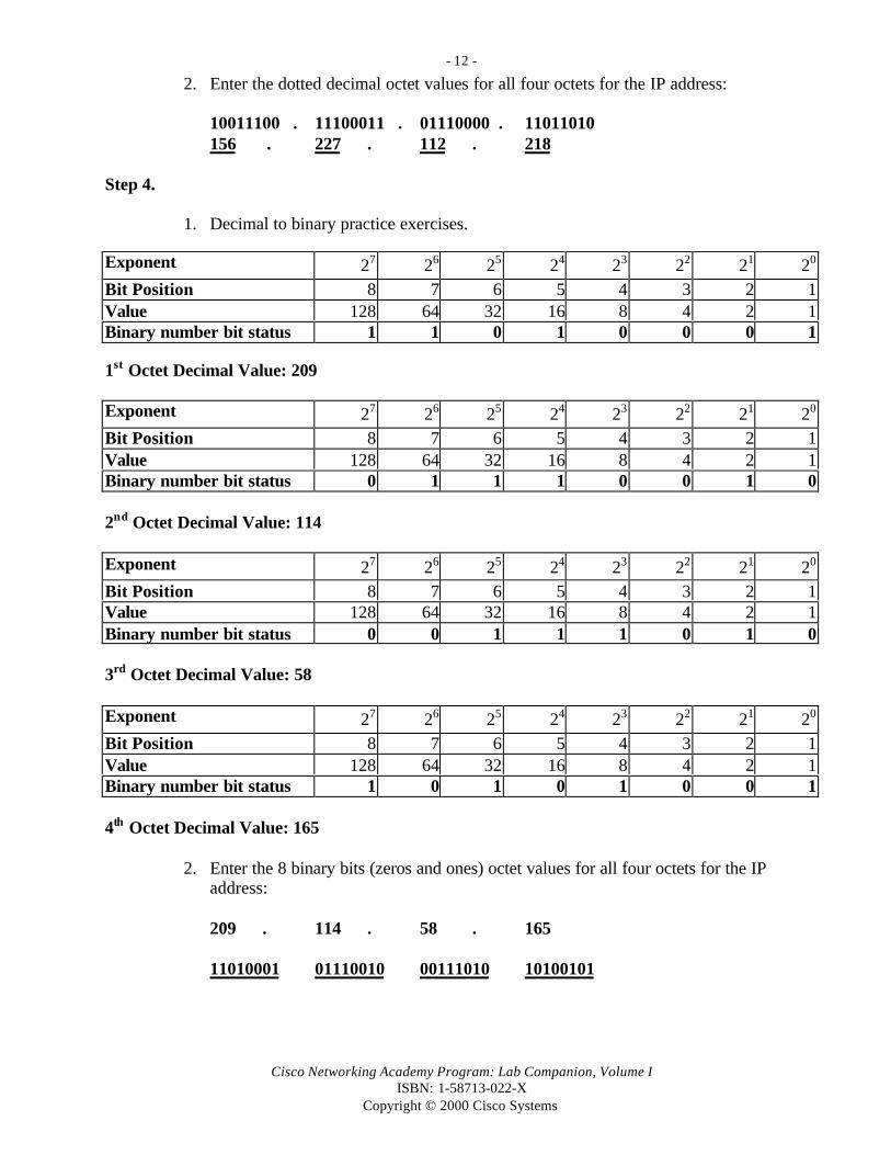
2. Enter the dotted decimal octet values for all four octets for the IP address:
10011100 . 11100011 . 01110000 . 11011010156 . 227 . 112 . 218
Step 4.
1. Decimal to binary practice exercises.
Exponent 27 26 25 24 23 22 21 20
Bit Position 8 7 6 5 4 3 2 1Value 128 64 32 16 8 4 2 1Binary number bit status 1 1 0 1 0 0 0 1
1st Octet Decimal Value: 209
Exponent 27 26 25 24 23 22 21 20
Bit Position 8 7 6 5 4 3 2 1Value 128 64 32 16 8 4 2 1Binary number bit status 0 1 1 1 0 0 1 0
2nd Octet Decimal Value: 114
Exponent 27 26 25 24 23 22 21 20
Bit Position 8 7 6 5 4 3 2 1Value 128 64 32 16 8 4 2 1Binary number bit status 0 0 1 1 1 0 1 0
3rd Octet Decimal Value: 58
Exponent 27 26 25 24 23 22 21 20
Bit Position 8 7 6 5 4 3 2 1Value 128 64 32 16 8 4 2 1Binary number bit status 1 0 1 0 1 0 0 1
4th Octet Decimal Value: 165
2. Enter the 8 binary bits (zeros and ones) octet values for all four octets for the IP address:
209 . 114 . 58 . 165
11010001 01110010 00111010 10100101

- 13 -
Cisco Networking Academy Program: Lab Companion, Volume IISBN: 1-58713-022-X
Copyright © 2000 Cisco Systems
Cisco Labs–Semester 1–Networking FundamentalsEXERCISE 2.2.5–OSI MODEL LAYERS–ANSWERS
Step 1
1. List the 7 layers of the OSI model from the top to the bottom. Give a mnemonic word for eachlayer that can help you remember it and then list the key terms and phrases that describe thecharacteristics and function of each.
Layer # Name Mnemonic Key Words and Description of Function7 Application All Network processes applications such as File, Print,
Message, Database, and Application services.Establishes availability of resources between twonodes. (FTP and Telnet are examples.)
6 Presentation People Data representation, coding (EBCDIC, ASCII),data transfer syntax, conversion, encryption,formatting, and compression services.
5 Session Seem Interhost communication. Establishes, maintains,and terminates connections between applications.
4 Transport To End-to-end connections. Segments andreassembles data in proper sequence. Setup andteardown of “virtual circuits” (connection-oriented). Can ensure segment delivery with errorcorrection, recovery, and flow control.
3 Network Need Network/host addresses and selection of best paththrough an internetwork (routing). Encapsulatesupper-layer information into “packets.”
2 Data Link Data Access to media. Adds frame header to upper-layer information which contains the hardwareaddress of the destination device or next device onthe path. The data link layer is divided into 2 sub-layers. 1) The Logical Link Control (LLC) and 2)The Media Access Control (MAC).
1 Physical Processing Binary transmission signals and encoding.Electrical (copper), light (fiber) and physicalconnections and media (cabling) between networkdevices.

- 14 -
Cisco Networking Academy Program: Lab Companion, Volume IISBN: 1-58713-022-X
Copyright © 2000 Cisco Systems
2. List the 7 layers of the OSI model. List the encapsulation unit used to describe the logicalgrouping of bits at each layer and the concepts and physical devices that operate at each layer.
Layer # Name EncapsulationUnit or LogicalGrouping
Devices or Components That Operate atThis Layer
7 Application Data Software (gateways)
6 Presentation Data Software
5 Session Data Software
4 Transport Segments Router
3 Network Packets,Datagrams
Router
2 Data Link Frames NIC (LLC and MAC), Bridge, Switch
1 Physical Bits NIC (Physical connectors–BNC, RJ45,and so on), Media (cable), Repeater, Hub,DCE, and DTE
- 15 -
Cisco Networking Academy Program: Lab Companion, Volume IISBN: 1-58713-022-X
Copyright © 2000 Cisco Systems
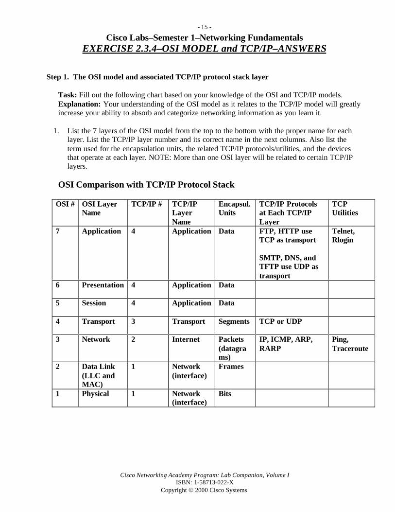
Cisco Labs–Semester 1–Networking FundamentalsEXERCISE 2.3.4–OSI MODEL and TCP/IP–ANSWERS
Step 1. The OSI model and associated TCP/IP protocol stack layer
Task: Fill out the following chart based on your knowledge of the OSI and TCP/IP models.Explanation: Your understanding of the OSI model as it relates to the TCP/IP model will greatlyincrease your ability to absorb and categorize networking information as you learn it.
1. List the 7 layers of the OSI model from the top to the bottom with the proper name for eachlayer. List the TCP/IP layer number and its correct name in the next columns. Also list theterm used for the encapsulation units, the related TCP/IP protocols/utilities, and the devicesthat operate at each layer. NOTE: More than one OSI layer will be related to certain TCP/IPlayers.
OSI Comparison with TCP/IP Protocol Stack
OSI # OSI LayerName
TCP/IP # TCP/IPLayerName
Encapsul.Units
TCP/IP Protocolsat Each TCP/IPLayer
TCPUtilities
7 Application 4 Application Data FTP, HTTP useTCP as transport
SMTP, DNS, andTFTP use UDP astransport
Telnet,Rlogin
6 Presentation 4 Application Data
5 Session 4 Application Data
4 Transport 3 Transport Segments TCP or UDP
3 Network 2 Internet Packets(datagrams)
IP, ICMP, ARP,RARP
Ping,Traceroute
2 Data Link(LLC andMAC)
1 Network(interface)
Frames
1 Physical 1 Network(interface)
Bits

- 16 -
Cisco Networking Academy Program: Lab Companion, Volume IISBN: 1-58713-022-X
Copyright © 2000 Cisco Systems
- 17 -
Cisco Networking Academy Program: Lab Companion, Volume IISBN: 1-58713-022-X
Copyright © 2000 Cisco Systems
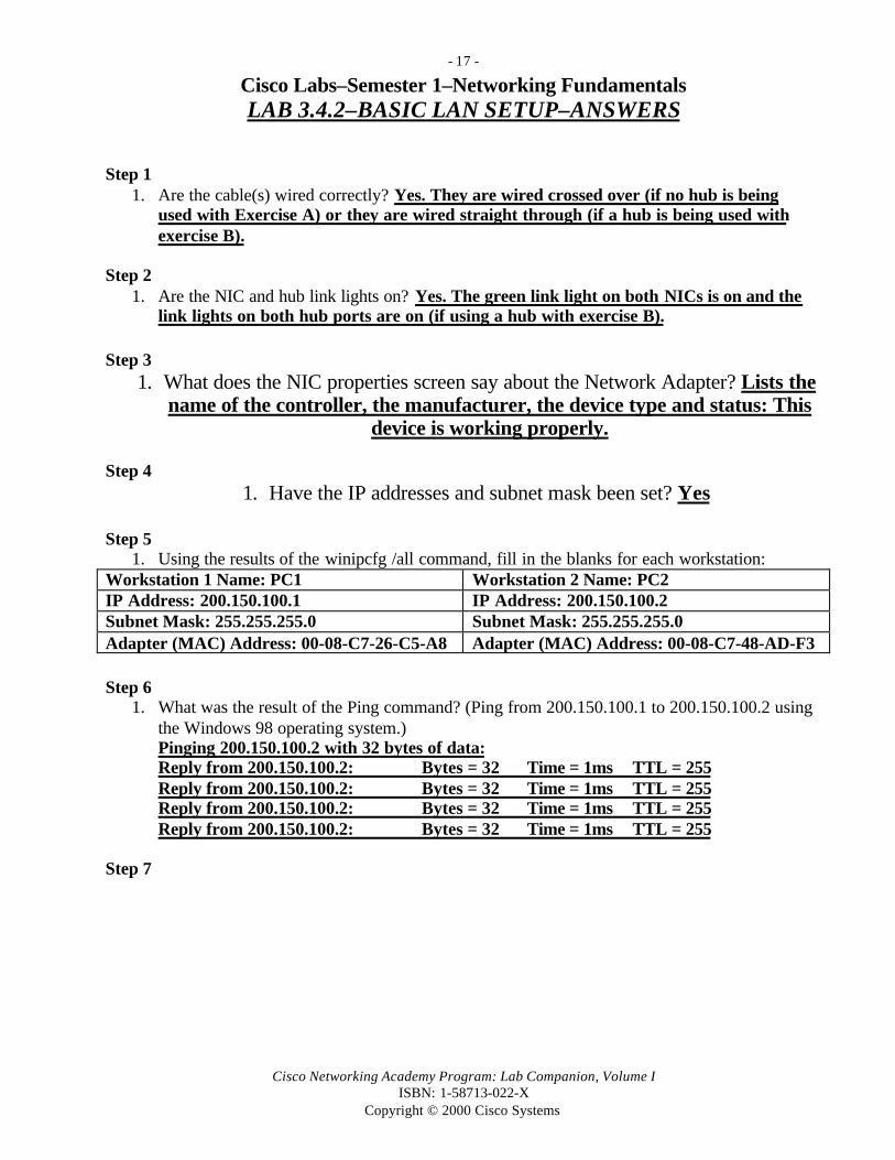
Cisco Labs–Semester 1–Networking FundamentalsLAB 3.4.2–BASIC LAN SETUP–ANSWERS
Step 11. Are the cable(s) wired correctly? Yes. They are wired crossed over (if no hub is being
used with Exercise A) or they are wired straight through (if a hub is being used withexercise B).
Step 21. Are the NIC and hub link lights on? Yes. The green link light on both NICs is on and the
link lights on both hub ports are on (if using a hub with exercise B).
Step 31. What does the NIC properties screen say about the Network Adapter? Lists the
name of the controller, the manufacturer, the device type and status: Thisdevice is working properly.
Step 41. Have the IP addresses and subnet mask been set? Yes
Step 51. Using the results of the winipcfg /all command, fill in the blanks for each workstation:
Workstation 1 Name: PC1 Workstation 2 Name: PC2IP Address: 200.150.100.1 IP Address: 200.150.100.2Subnet Mask: 255.255.255.0 Subnet Mask: 255.255.255.0Adapter (MAC) Address: 00-08-C7-26-C5-A8 Adapter (MAC) Address: 00-08-C7-48-AD-F3
Step 61. What was the result of the Ping command? (Ping from 200.150.100.1 to 200.150.100.2 using
the Windows 98 operating system.)Pinging 200.150.100.2 with 32 bytes of data:Reply from 200.150.100.2: Bytes = 32 Time = 1ms TTL = 255Reply from 200.150.100.2: Bytes = 32 Time = 1ms TTL = 255Reply from 200.150.100.2: Bytes = 32 Time = 1ms TTL = 255Reply from 200.150.100.2: Bytes = 32 Time = 1ms TTL = 255
Step 7

- 18 -
Cisco Networking Academy Program: Lab Companion, Volume IISBN: 1-58713-022-X
Copyright © 2000 Cisco Systems
1. List the networking components installed (answers will vary):Client (computer icon) Windows Family (or Windows Logon)
Adapter (NIC icon) Compaq NC3120 Fast Ethernet NICProtocol (net connection
icon)TCP/IP
OtherClient/Adapter/Protocol
There should be no others–Remove them if theyare present
Step 91. Document the results of the folder sharing and file creating process:
The folder on PC1 was shared and PC2 was able to connect to the shared folder and createa document in it.
- 19 -
Cisco Networking Academy Program: Lab Companion, Volume IISBN: 1-58713-022-X
Copyright © 2000 Cisco Systems
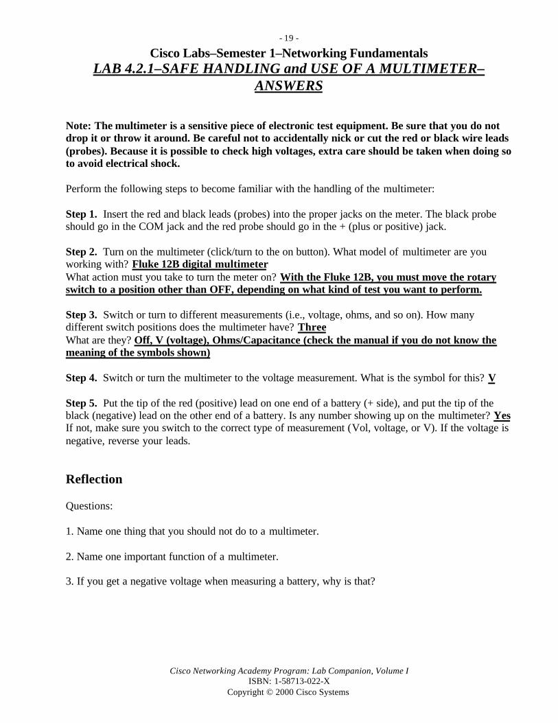
Cisco Labs–Semester 1–Networking FundamentalsLAB 4.2.1–SAFE HANDLING and USE OF A MULTIMETER–
ANSWERS
Note: The multimeter is a sensitive piece of electronic test equipment. Be sure that you do notdrop it or throw it around. Be careful not to accidentally nick or cut the red or black wire leads(probes). Because it is possible to check high voltages, extra care should be taken when doing soto avoid electrical shock.
Perform the following steps to become familiar with the handling of the multimeter:
Step 1. Insert the red and black leads (probes) into the proper jacks on the meter. The black probeshould go in the COM jack and the red probe should go in the + (plus or positive) jack.
Step 2. Turn on the multimeter (click/turn to the on button). What model of multimeter are youworking with? Fluke 12B digital multimeterWhat action must you take to turn the meter on? With the Fluke 12B, you must move the rotaryswitch to a position other than OFF, depending on what kind of test you want to perform.
Step 3. Switch or turn to different measurements (i.e., voltage, ohms, and so on). How manydifferent switch positions does the multimeter have? ThreeWhat are they? Off, V (voltage), Ohms/Capacitance (check the manual if you do not know themeaning of the symbols shown)
Step 4. Switch or turn the multimeter to the voltage measurement. What is the symbol for this? V
Step 5. Put the tip of the red (positive) lead on one end of a battery (+ side), and put the tip of theblack (negative) lead on the other end of a battery. Is any number showing up on the multimeter? YesIf not, make sure you switch to the correct type of measurement (Vol, voltage, or V). If the voltage isnegative, reverse your leads.
Reflection
Questions:
1. Name one thing that you should not do to a multimeter.
2. Name one important function of a multimeter.
3. If you get a negative voltage when measuring a battery, why is that?

- 20 -
Cisco Networking Academy Program: Lab Companion, Volume IISBN: 1-58713-022-X
Copyright © 2000 Cisco Systems
Cisco Labs–Semester 1–Networking FundamentalsLAB 4.2.2–RESISTANCE MEASUREMENTS–ANSWERS
Step 1. Move the rotary selector to the Omega symbol for Ohms (red Ω) in order to measureresistance. Press the button that has the Ohms symbol (red Ω) on it to select between resistancemeasurements and continuity.
Resistance Measurements: The screen will show Ω (ohms), KΩ (kilohms = thousands of Ohms) orMΩ (megohms = millions of Ohms). Use the Range button to change the range of resistance to bemeasured based on what resistance you expect to get. If you expect low resistance (less than 10ohms), select a low scale (like Ω). If you expect a high reading (over 10,000 ohms), select a highscale (like KΩ). If the resistance reading is over the range selected, the OL or Over Limit indicatorwill be displayed on the screen. The resistance setting is for measuring exact amounts of resistance.
Continuity Measurements: The screen will show a diode symbol, which is a small black trianglepointing to a vertical bar. A diode is an electronic device that either passes or blocks electricalcurrent. You might see a small sound symbol next to it, which means that when there is goodcontinuity (no resistance), the beep will sound. The continuity setting is used when you just want toknow if there is a good path for electricity and don’t care about the exact amount of resistance.
Step 2. Check the following resistances. Turn the meter off when finished or battery will drain.Item to Measure theResistance of
Set Selector andRange Scale to
Resistance Reading
1000 Ω Resistor KΩ with rangedisplay of 0.L
About 1000 Ohms
10 kΩ Resistor KΩ with rangedisplay of 0.L
About 10,000 Ohms
Graphite marking from apencil on a piece of paper
KΩ with rangedisplay of 0.L
From 10,000 to 100,000 Ohms, depending on thelength of the mark and how hard you press(longer marks = higher resistance reading)
Cat 5 jack Ω with rangedisplay of 0L
Less than 0.3Ω contact resistance; Over Limit(OL) on insulator
0.2 m section of Cat 5UTP solid cable
Ω with rangedisplay of 0L
Less than 0.3Ω contact resistance; Over Limit(OL) on insulator
Touch red and blackprobe contacts together
Ω with rangedisplay of 0L
Less than 0.2Ω (the harder you press, the lowerthe resistance reading)
Your own body (touchthe tips of the probes withyour fingers)
MΩ with rangedisplay of 0L
Stable readings will be hard to obtain, butdepending on sweatiness and grip, from 100,000(100kΩ) to 1,000,000 (MΩ) readings are typical
BNC terminated coaxialcable
Diode symbol(continuity scale)
Should show nearly 0 resistance or beeping sound
Unconnected DB9 toRJ45 adapter
Diode symbol(continuity scale)
Should show nearly 0 resistance or beeping sound(you can use the console cable adapter)
Terminated Cat 5 UTPpatch cable
Diode symbol(continuity scale)
Less than 0.3 W contact resistance on the wire;Over Limit (OL) on insulator

- 21 -
Cisco Networking Academy Program: Lab Companion, Volume IISBN: 1-58713-022-X
Copyright © 2000 Cisco Systems

- 22 -
Cisco Networking Academy Program: Lab Companion, Volume IISBN: 1-58713-022-X
Copyright © 2000 Cisco Systems
Cisco Labs–Semester 1–Networking FundamentalsLAB 4.2.3–VOLTAGE MEASUREMENTS–ANSWERS
Step 1. Move the rotary selector to the V symbol for voltage (black V) in order to be able to measurevoltage. Press the button that has the VDC and VAC symbol select between Direct Current (DC) andAlternating Current (AC) measurements.
Direct Current Measurements: The screen will show a V (voltage) with a series of dots and a lineover the top. There are several scales available depending on the voltage to be measured. They startfrom millivolts (abbreviated mV = 1000th of a volt) to voltages up to hundreds of volts. Use theRange button to change the range of DC voltage to be measured based on what voltage you expect tomeasure. Batteries (less than 15 volts) can typically be measured accurately with the VDC scale and0.0 range. DC voltage measurements can be used to determine if batteries are good or if there isvoltage coming out of an AC adapter (transformer or converter). These are common and are usedwith hubs, modems, laptops, printers, and other peripherals. These adapters can take wall outlet ACvoltage and step it down to lower AC voltages for the device attached or can convert the AC voltageto DC and step it down. Check the back of the adapter to see what the input (AC) and output voltages(AC or DC) should be.
Alternating Current Measurements: The screen will show a V (voltage) with a tilde (~) after it.This represents alternating current. There are several scales available depending on the voltage to bemeasured. They start from millivolts (abbreviated mV = 1000th of a volt) to voltage up to hundredsof volts. Use the Range button to change the range of AC voltage to be measured based on whatvoltage you expect to measure. Voltage from power outlets (120v or greater) can typically bemeasured accurately with the VAC scale and 0.0 range. AC voltage measurements are useful indetermining if there is adequate voltage coming from an AC outlet to power the equipment pluggedin.
Use a Fluke 12B multimeter (or equivalent) to measure the voltage of each of the following:
Step 2. Check the following voltages. Be sure to turn the meter off when finished.Item to Measure the Voltage of Set Selector and Range
Scale toVoltage Reading
Batteries: A cell (AA, AAA), C cell, Dcell, 9 Volts, 6 V lantern
VDC range display of0.0
Good AA battery is1.6v or higher
Duplex wall outlet (typically 120v) VAC range display of0.0
120v or higher
Power supply (converts AC to DC) forlaptop, or other networking electricaldevice)
VDC or VAC rangedisplay of 0.0 (read backof adapter to check forwhat output should be)
From 4 to 20 VACor VDC (will vary)
(Optional) A lemon with a galvanizednail stuck in one side and a piece ofuninsulated copper wire stuck in theopposite side
VDC range display of0.0
Varies
Reflection Question: Why might you want to measure voltage when troubleshooting a network?

- 23 -
Cisco Networking Academy Program: Lab Companion, Volume IISBN: 1-58713-022-X
Copyright © 2000 Cisco Systems
______________________________________________________________________________

- 24 -
Cisco Networking Academy Program: Lab Companion, Volume IISBN: 1-58713-022-X
Copyright © 2000 Cisco Systems
Cisco Labs–Semester 1–Networking FundamentalsLAB 4.2.4–SERIES CIRCUITS–ANSWERS
Step 1. Measure the resistances of all devices and components except the battery. Measure thevoltage of the battery. All resistances should be less than 1 Ω (Ohm), except the light bulbs. All thedevices except the battery should register continuity (with the tone), indicating a short circuit or aconducting path.
Check the following resistances. Turn the meter off when finished or it will drain the battery.Item to Measure theResistance of
Set Selector andRange Scale to
Resistance Reading
Pieces of wire to connectcomponents
ΩΩ with rangedisplay of 0L
Less than 1 Ohm
Light switch ΩΩ with rangedisplay of 0L
Less than 1 Ohm
Light bulbs ΩΩ with rangedisplay of 0L
Between 10 and 15 Ohms
Step 2. Measure the voltage of the battery, unloaded (with nothing attached to it).
Item to Measure the Voltage of Set Selector and RangeScale to
Voltage Reading
Lantern battery (6 V) with no load VDC range display of0.0
6.0 v or higher
Step 3. Build a series circuit, one device at a time (use 1 battery, 1 switch, 1 bulb, and connectingwires). Connect the battery positive lead to the end of one wire and connect the negative lead to theother wire. If the switch is turned on, the bulb should light. Disconnect one thing and see that thecircuit is broken. Did the bulb go out? Yes
Step 4. Measure the battery voltage while the circuit is running. The switch should be turned on andthe light bulb should be lit. What was the voltage of the battery with the light bulb on? 6.0 +
Step 5. Add the second bulb in series and measure the battery voltage again. What was the voltage ofthe battery with the light bulb on? Should be slightly less than Step 4.
Reflection Question: How do series circuits apply to networking?Computer networks and networking devices contain millions of circuits. An understanding ofbasic series circuit terminology helps us understand these networks and devices without havingto know everything about how the more complex circuits work.

- 25 -
Cisco Networking Academy Program: Lab Companion, Volume IISBN: 1-58713-022-X
Copyright © 2000 Cisco Systems
Cisco Labs–Semester 1–Networking FundamentalsLAB 4.2.5–COMMUNICATIONS CIRCUIT–ANSWERS
Reflection Questions:
1. What issues arose as you tried to build your communications system that you think apply to data communications between computers? Answers should include most of the following:
• The issue of medium (Cat 5 was chosen).
• The issue of signaling (optical pulses from the light bulbs being turned on and off).
• The issue of encoding (what do the flashes of light represent).
• The issue of throughput (how many bits per second can they communicate).
• The issue of standards (if two groups do not communicate standards).
• The issue of simplex versus half-duplex versus full duplex communications.
• The issue of framing and error correction (how the start of a frame was indicated, how didthe other team indicate whether it received the frame or not).
• The issue of scalability–how will more nodes be added to the network.
2. Analyze your communications system in terms of the OSI layers.
Answers should include a reference to each layer of the OSI model and a brief discussion ofhow the team dealt with the concerns of that layer.

- 26 -
Cisco Networking Academy Program: Lab Companion, Volume IISBN: 1-58713-022-X
Copyright © 2000 Cisco Systems
Cisco Labs–Semester 1–Networking FundamentalsLAB 5.3.1–BASIC CABLE TESTER–ANSWERS
Answers:Answers will vary depending on the cables being tested and the problems they have.

- 27 -
Cisco Networking Academy Program: Lab Companion, Volume IISBN: 1-58713-022-X
Copyright © 2000 Cisco Systems
Cisco Labs–Semester 1–Networking FundamentalsLAB 5.3.2–STRAIGHT-THROUGH CABLE–ANSWERS
Answers: There are several methods that can be used to check the cable.Have the instructor check your cable and verify it using one or more of these tests:Visual Test: Inspect the cable ends visually. Hold the RJ45 connectors side by side. The same colorwire should be on the same pin. This is not a conclusive test but is a good start.Cable Test: You can test the cable with a cable tester to verify the wires have continuity (no breaks)and are not shorted.Functional Test: You can connect your cable from a workstation to a hub and verify that you can seeother workstations. This is the ultimate test but requires more setup and configuration time.

- 28 -
Cisco Networking Academy Program: Lab Companion, Volume IISBN: 1-58713-022-X
Copyright © 2000 Cisco Systems
Cisco Labs–Semester 1–Networking FundamentalsLAB 5.3.3–ROLLOVER CABLE–ANSWERS
Step 1. Review Cable Connections and Pin LocationsUse the following table as a reference to help create a rollover console cable.
Questions:1. Which signal on the Router port (column 1 of the table) will be used to transmit data (showing the
router prompt, and so on) to the PC when the PC is first connected and HyperTerminal is started?TxD
2. Which Pin is this connected to on the router end of the RJ45 cable? 3
3. Which pin is this connected to on the other end of the RJ45 cable? 6
4. Which pin is this connected to in the DB9 connector? 2
5. Which console device signal does this connect to? RxD
6. What would happen if Pin 3 on the left cable end were attached to pin 3 as with a straight-throughcable? Transmit Data (TxD) from the router would be connected to the Transmit Data(TxD) on the workstation, and they would never communicate.
A. Step 2. Use the following steps to build the rollover console cable.
8. Test the finished cable and have the instructor check it. How can you tell if your cable isfunctioning properly? There are several methods that can be used to check the cable.
Visual Test: The cable ends can be visually inspected and should be wired exactly opposite whenlooking at the conductors and holding the RJ45 connectors side by side with the clip facing down.If you hold the RJ45 connectors end to end with the clip facing down, the wire colors should match.Pinouts are listed in the table.
Cable Test: You can test the cable with a cable tester to verify the wires have continuity (no breaks)and are not shorted.
Functional Test: You can connect your rollover cable to the RJ45-to-DB9 terminal adapter andconnect a workstation to the router to verify that you can see the router console prompts. This is theultimate test and also requires that HyperTerminal be set up properly on the workstation (8 data bits,no parity, 2 stop bits).

- 29 -
Cisco Networking Academy Program: Lab Companion, Volume IISBN: 1-58713-022-X
Copyright © 2000 Cisco Systems
Cisco Labs–Semester 1–Networking FundamentalsLAB 5.3.4– CROSSOVER CABLE –ANSWERS
Answers: There are several methods that can be used to check the cable.Have the instructor check your cable and verify it using one or more of these tests:Visual Test: Inspect the cable ends visually. Hold the RJ45 connectors side by side. The same colorwire should be on the same pin. This is not a conclusive test but is a good start.Cable Test: You can test the cable with a cable tester to verify the wires have continuity (no breaks)and are not shorted.Functional Test: You can connect your cable from a workstation to a hub and verify that you can seeother workstations. This is the ultimate test but requires more setup and configuration time.

- 30 -
Cisco Networking Academy Program: Lab Companion, Volume IISBN: 1-58713-022-X
Copyright © 2000 Cisco Systems
Cisco Labs–Semester 1–Networking FundamentalsLAB 5.3.5–CABLE TESTER–WIRE MAP–ANSWERS
Step 1. Set the Advanced Cable Tester for the Desired cableThese instructions pertain to the Fluke 620 LAN Cablemeter. Turn the rotary switch selector on thetester to the WIRE MAP position. Press the SETUP button to enter the setup mode and observe theLCD screen on the tester. The first option should be CABLE. Press the UP or DOWN buttons untilthe desired cable type of UTP is selected. Press ENTER to accept that setting and go to the next one.Continue pressing the UP/DOWN arrows and pressing ENTER until the tester is set to the followingcabling characteristics:
Tester Option Desired SettingCABLE UTPWIRING 10BASE-T or EIA/TIA 4PRCATEGORY CAT 5WIRE SIZE AWG 24CAL to CABLE? NOBEEPING ON or OFFLCD CONTRAST From 1 thru 10 (brightest)
Step 2. Set up the Cable to be TestedFor each cable to be tested with the following tests, place the near end of the cable into the RJ45 jacklabeled UTP/FTP on the tester. Place the RJ45-RJ45 female coupler on the far end of the cable andthen insert the Cable Identifier into the other side of the coupler. The coupler and the cable identifierare accessories that come with the Fluke 620 LAN CableMeter:
Step 3. Perform Wire Map Testing.Using the tester’s Wire Map function and a Cable ID unit, you can determine the wiring ofboth the near and far ends of the cable. The top set of numbers displayed on the LCD screen isthe near end and the bottom set is the far end. Perform a Wire Map test on each of the cablesprovided and fill in the following table based on the result for each CAT 5 cable tested. Foreach cable, write down the number and color, whether the cable is straight-through orcrossover, the tester screen test results, and what you think the problem is. (Your answersmight vary.)
CableNo.
CableColor
How Cable isWired (Straight-Through orCrossover)
B. Tester Displayed TestResults
(Note: refer to the Fluke manualfor detailed description of testresults for wire map)
C. ProblemDescription
1 Red Straight-through Top: 1 2 3 6 4 5 7 8 IDBot: 1 2 3 6 4 5 7 8 #1
Wire is OK for astraight-through cable
2 Blue Straight-through Top: 1 2 3 6 o IDBot: 1 2 3 6 #1
Open (o means wireno. 2 open)
3 Yellow Straight-through Top: 2 3 1 6 IDBot: #1
Short (wires 2 & 3touching–near end)
4 Green Straight-through Top: 1 3 2 6 ID Split Pair

- 31 -
Cisco Networking Academy Program: Lab Companion, Volume IISBN: 1-58713-022-X
Copyright © 2000 Cisco Systems
Bot: 1 3 2 6 #15 Orange Crossover Top: 1 2 3 6 4 5 7 8 ID
Bot: 3 6 1 2 4 5 7 8 #1Wire is OK for acrossover cable

- 32 -
Cisco Networking Academy Program: Lab Companion, Volume IISBN: 1-58713-022-X
Copyright © 2000 Cisco Systems
Cisco Labs–Semester 1–Networking FundamentalsLAB 5.3.6–STRAIGHT-THROUGH CABLE TEST–ANSWERS
Step 1. Set the Advanced Cable Tester for the Desired cable (UTP or COAX)These instructions pertain to the Fluke 620 LAN CableMeter. Turn the rotary switch selector on thetester to the TEST position. Press the SETUP button to enter the setup mode and observe the LCDscreen on the tester. The first option should be CABLE. Press the UP or DOWN buttons until thedesired cable type of UTP or COAX (thinnet) is selected. Press ENTER to accept that setting and goto the next one. Continue pressing the UP/DOWN arrows and pressing ENTER until the tester is setto the following cabling characteristics:
Tester Option Desired Setting—UTP Desired Setting—COAXCABLE UTP COAXWIRING 10BASET or EIA/TIA 4PR 10BASE2 or RG58 (thinnet)CATEGORY CAT 5 N/AWIRE SIZE AWG 24 N/ACAL to CABLE? NO NOBEEPING ON or OFF ON or OFFLCD CONTRAST From 1 thru 10 (brightest) From 1 thru 10 (brightest)
Step 2. Set up the Cable to be Tested (UTP or COAX)For each UTP cable to be tested with the following tests, place the near end of the cable into the RJ45jack labeled UTP/FTP on the tester. Place the RJ45-RJ45 female coupler on the far end of the cableand then insert the Cable Identifier into the other side of the coupler. The coupler and the cableidentifier are accessories that come with the Fluke 620 LAN CableMeter. Multiple Cable IDs withdifferent numbers can be purchased to help in identify which cable you are working with. For coaxcables, insert one end of the BNC connector into the jack labeled COAX on the tester. Coax cablesshould not have a terminating resistor.
Step 3. Perform Basic Cable Test–Pass/Fail FunctionUsing the tester’s Test function and a Cable ID unit (for UTP), you can determine thefunctionality of the cable. Perform a basic cable test on each of the cables provided and fill inthe following table based on the result for each cable tested. For each cable, write down thenumber and color, whether the cable is straight-through, crossover, or coaxial, the tester screentest results, and what you think the problem is. The Cable ID can be used to identify aparticular cable by moving it to another cable. (Your answers might vary.)
CableNo.
CableColor
How Cable IsWired(UTP or COAX)
D. Tester Displayed Test Results(Note: refer to the Fluke manual fordetailed description of test results)
E. ProblemDescription
1 Red Straight-throughUTP
Top: PASS IDBot: 7' #1
Wire is OK for astraight-through
2 Blue Straight-throughUTP
Top: FAIL ID #1Bot: 1 2 SHORT <8'
Short (wires 1 & 2touching appx. 8')
3 Yellow Straight-throughUTP
Top: FAIL ID #1Bot: 1 2 OPEN @7'
Open (wires 1 and2 open at far end 7')
4 Black Thinnet Coax(RG58)–No cable
COAX SHORT < 12' Center conductortouching braided

- 33 -
Cisco Networking Academy Program: Lab Companion, Volume IISBN: 1-58713-022-X
Copyright © 2000 Cisco Systems
ID used sheathing appx 12'

- 34 -
Cisco Networking Academy Program: Lab Companion, Volume IISBN: 1-58713-022-X
Copyright © 2000 Cisco Systems
Cisco Labs–Semester 1–Networking FundamentalsLAB 5.3.7–CABLE TESTER–LENGTH–ANSWERS
Step 1. Set the Advanced Cable Tester for the Desired cable (UTP or COAX)These instructions pertain to the Fluke 620 LAN CableMeter. Turn the rotary switch selector on thetester to the LENGTH position. Press the SETUP button to enter the setup mode and observe theLCD screen on the tester. The first option should be CABLE Press the UP or DOWN buttons untilthe desired cable type of UTP or COAX (thinnet) is selected. Press ENTER to accept that setting andgo to the next one. Continue pressing the UP/DOWN arrows and pressing ENTER until the tester isset to the following cabling characteristics, depending on the type of cable you will be testing:
Tester Option Desired Setting—UTP Desired Setting—COAXCABLE UTP COAXWIRING 10BASET or EIA/TIA 4PR 10BASE2 or RG58 (thinnet)CATEGORY CAT 5 N/AWIRE SIZE AWG 24 N/ACAL to CABLE? NO NOBEEPING ON or OFF ON or OFFLCD CONTRAST From 1 thru 10 (brightest) From 1 thru 10 (brightest)
Step 2. Set up the Cable to be Tested (UTP or COAX)For each UTP cable to be tested with the following tests, place the near end of the cable into the RJ45jack labeled UTP/FTP on the tester. Place the RJ45-RJ45 female coupler on the far end of the cableand then insert the Cable Identifier into the other side of the coupler. The coupler and the cableidentifier are accessories that come with the Fluke 620 LAN CableMeter. For coax cables, insert oneend of the BNC connector into the jack labeled COAX on the tester. Coax cables should not beterminated. If tested with a terminating resistor (50Ω), the display will be the resistance of the cableplus the terminating resistor.
Step 3. Perform Cable Length Test FunctionUsing the tester’s Test function and a Cable ID unit (for UTP), you can determine thefunctionality of the cable. Perform a basic cable test on each of the cables provided and fill inthe following table based on the result for each CAT 5 cable tested. For each cable, write downthe number and color, whether the cable is straight-through, crossover, or coaxial, the testerscreen test results, and what you think the problem is. For UTP cables, press the down arrowor up arrow to see all pairs.
CableNo.
CableColor
How Cable IsWired(UTP or COAX)
F. Tester Displayed Test Results(Note: refer to the Fluke manual fordetailed description of test results)
G. Problem
1 Red Straight-throughUTP
1 2 7'3 6 7'4 5 7'7 8 7'
Wire is OK for astraight-through.All 4 pairs are 7'long.
2 Blue Straight-throughUTP
1 2 12'3 6 12'4 5 12'7 8 12'
Wire is OK for astraight-through.All 4 pairs are 12'long.

- 35 -
Cisco Networking Academy Program: Lab Companion, Volume IISBN: 1-58713-022-X
Copyright © 2000 Cisco Systems
3 Black Thinnet Coax(RG58)
COAX 8' Wire is OK forcoax–8' long.

- 36 -
Cisco Networking Academy Program: Lab Companion, Volume IISBN: 1-58713-022-X
Copyright © 2000 Cisco Systems
Cisco Labs–Semester 1–Networking FundamentalsLAB 7.6.2–NETWORK DISCOVERY–ANSWERS
1. If you have not done so already, install Network Inspector software (the “Agent” and the“Console”) on your PC. How will you know you are done with this step?The icons for both programs should appear in your Program Directory Menu.
2. Make sure you are connected to a working Ethernet network. What are some signs that you are onthe network? The link light on your NIC is lit and the other LED is indicating networktraffic. You examine your cable run and note that you are connected to a hub or switch.You are able to send and receive e-mail and access the Internet (if your network isconnected). You can “ping” other machines’ IP addresses. And so on.
3. Open Fluke Network Inspector Agent. You will be prompted to do something. What are youprompted to do and why do you suppose you must do this? Click OK when finished.You will be prompted to decide which interface, specifically which Network InterfaceAdapter, you want to study. Many PCs will have multiple adapters installed (perhaps onefor modem, one for Ethernet, and others); you must choose one for the software to study.
4. Now the Agent will prompt you with a status screen. Click on the tabs and write down what arethe major categories of things you can control about the Agent. Under the database/address tab,click on “overwrite” so that the new data you are collecting will be stored in the database. ClickApply. Agent, Database/Address, SNMP, Problems, Advanced, About
5. Start the Agent. What is the status shown? What does the status change to after a few minutes?What do you suppose is happening? Minimize the Agent. The status first changes from “stop”to “start pending,” then “running.” The agent is discovering your network.
6. Open Fluke Network Inspector Console. What do you see? You see the console interface andthe database being filled with discovered devices.
7. Allow the Agent to run for a few minutes. What do you see? The database has filled withinformation.
8. Stop the Agent and minimize the Agent screen. What significant information about the networkhave you obtained? Write down a few complete lines of the database. You obtain iconsindicating the type of device, device identifier names, IP addresses, IPX addresses (if any),NetBIOS addresses (if any), and MAC addresses. All crucial information for managing yournetwork.

- 37 -
Cisco Networking Academy Program: Lab Companion, Volume IISBN: 1-58713-022-X
Copyright © 2000 Cisco Systems
9. In the left of the control panel, click each of the “Devices” and explain briefly what they are:“Fluke Tools,” “Key Devices,” “Utilization Sources,” “SNMP Agents,” “Servers,” “Routers,”“Switches,” “Printers,” and “Hosts.” Fluke Tools–other Fluke hardware devices that can beattached at other points in the network to help study it; Key Devices–servers, switches,routers; Utilization sources–which devices are causing network traffic; SNMP Agents–devices that use the Simple Network Management Protocol to report network information;Servers–computers that provide services to client computers; Routers–Layer 3 pathdetermination and switching devices; Switches–Layer 2 multiport bridges; Printers–common peripheral devices; Hosts–PCs on the network.
10. Close the Agent and the Console. You have begun using a very powerful piece of software.
Reflection: Imagine you have earned your CCNA and are working in a medium-sized company.Write in your journal what value you see in using Network Management software.As a newly hired CCNA, one of the first tasks you might be given is to study the existingnetwork. No doubt some amount of sneakernet is in order–walk around, talk to people, look inwiring closets. But, network discovery will greatly assist you in documenting and studying thecurrent status of the network.

- 38 -
Cisco Networking Academy Program: Lab Companion, Volume IISBN: 1-58713-022-X
Copyright © 2000 Cisco Systems
Cisco Labs–Semester 1–Networking FundamentalsLAB 7.6.3–NETWORK INSPECTOR PROBLEM LOG–ANSWERS
1. Make sure you are connected to the network. How can you verify this? The link light on yourNIC is lit and the other LED is indicating network traffic. You examine your cable run andnote that you are connected to a hub or switch. You are able to send and receive e-mail andaccess the Internet (if your network is connected). You can “ping” other machines’ IPaddresses. And so on.
2. Log in to Network Inspector Agent, set Database tab to overwrite, and start the agent running.The agent should indicate it is running.
3. Open Network Inspector Console, and watch until network discovery appears to have stopped.Stop the agent. Depending on the size of your network, this might take a few seconds.
4. Go to Help/About the problem log and troubleshooting problems/errors, warnings, and changesthat can be discovered–does a list appear? Yes, 3 lists appear detailing the errors, warnings,and changes that can be discovered. Many of these are common network managementproblems.
5. Review the list. Choose 3 errors, 3 warnings, and 3 changes that you believe are important, and
describe them in your own words. Students should use the online help to obtain these
descriptions.
6. Return to database view. Are there any errors, warnings, and changes that have appeared? If yourinstructor tells you to, try starting and stopping the agent again, rediscovering the network, andseeing if the instructor has caused any errors, warnings, or changes. Note these changes in yourjournal.
7. Can you draw a topology of the network based on the IP addresses and subnetwork informationobtained? Go ahead and try. Yes, topology information can be obtained by grouping hostsby subnet and inferring things like router ports and switch placement. (Note that if youhave NI 4.0, you can obtain this topology automatically.)
Reflection:Imagine you are a network administrator. Describe how this software would be useful to you.Network administrators often have to keep track of dozens or hundreds of computers, onseveral or more subnetworks, with routers, switches, and servers all around the network. Evenin a well-designed and well-run network, keeping track of all of the IP addresses, MACaddresses, descriptions, and topology of these devices can be a challenge. Network Inspectorand other network management software make this task easier, especially as users’ needs (andhence the network topology) change.

- 39 -
Cisco Networking Academy Program: Lab Companion, Volume IISBN: 1-58713-022-X
Copyright © 2000 Cisco Systems
Cisco Labs–Semester 1–Networking FundamentalsLAB 7.6.4–PROTOCOL INSPECTOR FRAME STATS–ANSWERS
1. Make sure the PC is connected to your local-area network (LAN), which preferably is connected
to the Internet. What are some ways to determine if your PC is connected to the LAN? The link
light on your NIC is lit and the other LED is indicating network traffic. You examine your
cable run and note that you are connected to a hub or switch. You are able to send and
receive e-mail and access the Internet (if your network is connected). You can “ping” other
machines’ IP addresses. And so on.
2. Install the protocol analysis software onto your computer (unless you have already done so). ForProtocol Inspector, you must be sure that you have installed the correct NDIS 802.3 module as aResource in Protocol Inspector. You will probably need to see several NDIS 802.3 modules asresources, corresponding to different installed adapters on your PC. The Protocol Inspector canonly look at one of these adapters at a time, which you must choose. Open the Protocol Inspectorprogram. Do you see multiple adapters in the resource window? (Your instructor might need tospecify which one. Note that if you are doing captures and you see no traffic whatsoever, you areprobably looking at the wrong resource.)
3. Choose the correct module with a double-click. Describe the 2 graphs and the 6 tabs that appear.Write down and explain everything that appears in the Description tab. Two graphs–utilizationand errors–appear. 6 tabs–monitor, RX, TX, Alarm, Alarm Log, and Description–appear.
4. Click the start button (1st line of icons, 3rd icon from the left) and see if the utilization graphincreases above zero (displayed as blue sections on the graph). This indicates network traffic(perhaps switch or router or DNS updates). If after about 20 seconds you don’t see anything,that’s OK; click the stop button. You are about to start your own traffic. Depending on networkconditions, you might or might not see traffic. Most likely on the classroom network thiswill not be an issue.
5. In another window, open your e-mail program and prepare to send a simple e-mail to yourself.But don’t send it yet! E-mail, Browsers, or any applications that use the network adapter youselected are fine.
6. Click the start button. Watch the utilization graph as your e-mail is transmitted and then received.Check your e-mail until you get the second blue “bump” indicating receipt of the e-mail, thenclick the stop icon. If your network is such that the delay for receipt of e-mails is too long forclass time, just watching the transmitted e-mail is fine.

- 40 -
Cisco Networking Academy Program: Lab Companion, Volume IISBN: 1-58713-022-X
Copyright © 2000 Cisco Systems
7. Check the RX tab. Look at the MAC counters column. What types of frames were received?What does each type mean? Look at the errors column (7 are listed). Imagine what the differenttypes of frame errors are, and put, in your own words, what you think they mean. Frame typesinclude broadcast (to all MAC addresses), multicast (to a group of MAC addresses), or unicast (toone MAC address). Frame errors include CRC alignment (frame accuracy measurements),undersize frames (for Ethernet, less than 64 bytes), oversize frames (for Ethernet, >1518bytes), fragments (parts of collided frames), jabbers (frames larger than 1518 bytes andwith bad CRC values), collisions (two frames on the same medium at the same time), andpackets dropped.
8. At the top left of the window there should be two lines of icons. On the second line of icons,6th from the left, is the Detail View icon. Click it and describe what happens. An entirely newwindow, with many more icons on top and the monitor view still running, is opened.
9. From detail view, stop the capture. On the first line of icons, select the yellow “file cabinet” 8th
from the left of “Capture View.” What happens? A large, complex database appears. This willbe studied in later labs.
10. Take a view, scrolling down looking at all the frames and all of the protocols involved in a simplee-mail.
11. Now try out the other views: MAC statistics, Frame Size Distribution Monitor, Protocol statistics,Network Layer Host Table, Application Layer Host Table, Host Matrix, Network Layer Matrix.Comment on each. Each view gives a different graphical representation of thecommunication “conversations” that have occurred and been captured.
Reflection:
1. Has this program given you a new perspective on frames? Explain.
Hopefully the students now see frames as a more tangible part of computer network
operation.
2. Does the number of protocol frames for even a simple e-mail request surprise you? Why or whynot? There’s no right answer to this question; for many students it might be surprising thatthe operations that appear simple have a much more complex layer.
3. Did this lab change the way you view the functioning of computer networks? Explain.Hopefully the students will now be wondering about all of the different protocols that they haveglimpsed in the database. Chapters 10–15 will focus on these details. Use this moment in thecourse to contextualize what they have learned and what is forthcoming.
- 41 -
Cisco Networking Academy Program: Lab Companion, Volume IISBN: 1-58713-022-X
Copyright © 2000 Cisco Systems
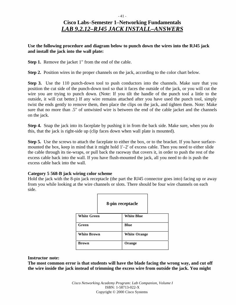
Cisco Labs–Semester 1–Networking FundamentalsLAB 9.2.12–RJ45 JACK INSTALL–ANSWERS
Use the following procedure and diagram below to punch down the wires into the RJ45 jackand install the jack into the wall plate:
Step 1. Remove the jacket 1" from the end of the cable.
Step 2. Position wires in the proper channels on the jack, according to the color chart below.
Step 3. Use the 110 punch-down tool to push conductors into the channels. Make sure that youposition the cut side of the punch-down tool so that it faces the outside of the jack, or you will cut thewire you are trying to punch down. (Note: If you tilt the handle of the punch tool a little to theoutside, it will cut better.) If any wire remains attached after you have used the punch tool, simplytwist the ends gently to remove them, then place the clips on the jack, and tighten them. Note: Makesure that no more than .5" of untwisted wire is between the end of the cable jacket and the channelson the jack.
Step 4. Snap the jack into its faceplate by pushing it in from the back side. Make sure, when you dothis, that the jack is right-side up (clip faces down when wall plate is mounted).
Step 5. Use the screws to attach the faceplate to either the box, or to the bracket. If you have surface-mounted the box, keep in mind that it might hold 1'–2' of excess cable. Then you need to either slidethe cable through its tie-wraps, or pull back the raceway that covers it, in order to push the rest of theexcess cable back into the wall. If you have flush-mounted the jack, all you need to do is push theexcess cable back into the wall.
Category 5 568-B jack wiring color schemeHold the jack with the 8-pin jack receptacle (the part the RJ45 connector goes into) facing up or awayfrom you while looking at the wire channels or slots. There should be four wire channels on eachside.
White Green White Blue
Green Blue
White Brown White Orange
Brown Orange
Instructor note:The most common error is that students will have the blade facing the wrong way, and cut offthe wire inside the jack instead of trimming the excess wire from outside the jack. You might
8-pin receptacle

- 42 -
Cisco Networking Academy Program: Lab Companion, Volume IISBN: 1-58713-022-X
Copyright © 2000 Cisco Systems
want to point out that this same procedure is used to punch down into a patch panel, anothernecessary skill for cable installation.

- 43 -
Cisco Networking Academy Program: Lab Companion, Volume IISBN: 1-58713-022-X
Copyright © 2000 Cisco Systems
Cisco Labs–Semester 1–Networking FundamentalsLAB 9.5.1–DEMO CABLE INSTALLATION–ANSWERS
Proper technique is described in the curriculum Learning Objective 9.4. Safety must be
emphasized first, then professional installation (quality punchdowns, proper cable routing and
mounting procedures). It is probably most efficient to have the students demonstrate their skills
in teams.
There is considerable flexibility with this lab, and there are many options for how to run thecable. Answers will vary considerably. The necessary tools and samples of components shouldbe available for demonstration. Some or all of the following cabling tasks can be demonstratedby the instructor and performed by the students, depending on the resources and facilitiesavailable. The main things to look for are clean and neat cable runs with no kinks and goodconnections. At a minimum, the students should punch down an RJ45 jack and run a piece ofcable to a patch panel to simulate a cable run from a workstation from a PC workstation to anIDF or MDF.
1. Fish cable from above.
2. Fish cable from below.
3. String cable through a dropped ceiling space.
4. Wall mount cable by using tie-wraps.
5. Wall mount cable by using decorative raceway.
6. Wall mount cable by using gutter.
7. Mount cable by using a ladder rack.
8. String cable by using a telepole.
9. String cable by using fish tape.
10. String cable using pull string.

- 44 -
Cisco Networking Academy Program: Lab Companion, Volume IISBN: 1-58713-022-X
Copyright © 2000 Cisco Systems
Cisco Labs–Semester 1–Networking FundamentalsLAB 9.7.13–DEMO CABLE TESTING–ANSWERS
You should be able to take the cable run created in Lab 9.5.1.1 and test it by connecting aworkstation with a NIC to an RJ45 straight-through patch cable and then into the wall plate(RJ45 jack). Connect another RJ45 straight-through patch cable from the patch panel to a hubor switch and make sure the switch is plugged in. If the link lights on the NIC and the hub orswitch come on, you have a good connection. You can also use the Fluke CableMeter or a basiccable tester to verify the cable run is good using the following steps. Results will vary dependingon the resources and facilities available.
1. Complete a cable run.
2. Use the Fluke 620 Meter on Wire Map to test the installation.
3. Identify any faults as near-end, along the cable, or far-end.
4. Correct the faults.
5. Retest until the cable run passes on the Fluke Meter.
6. Label the cable run (alphanumeric identification) as passed and record in your journal.
7. (Optional) Using the continuity meter, test two straight-through patch cords–one can be short, butthe other must make up the entire rest of the distance from jack to patch panel. Test both patchcables on the continuity tester.
8. (Optional) Connect both cables to the continuity tester. If all of the light pairs (1 to 1, 2 to 2, 3 to3, and so on; up to 8 to 8) light up, you have demonstrated at least the continuity.
9. (Optional) Perform high-end tests on the cable run with more expensive test equipment.
- 45 -
Cisco Networking Academy Program: Lab Companion, Volume IISBN: 1-58713-022-X
Copyright © 2000 Cisco Systems
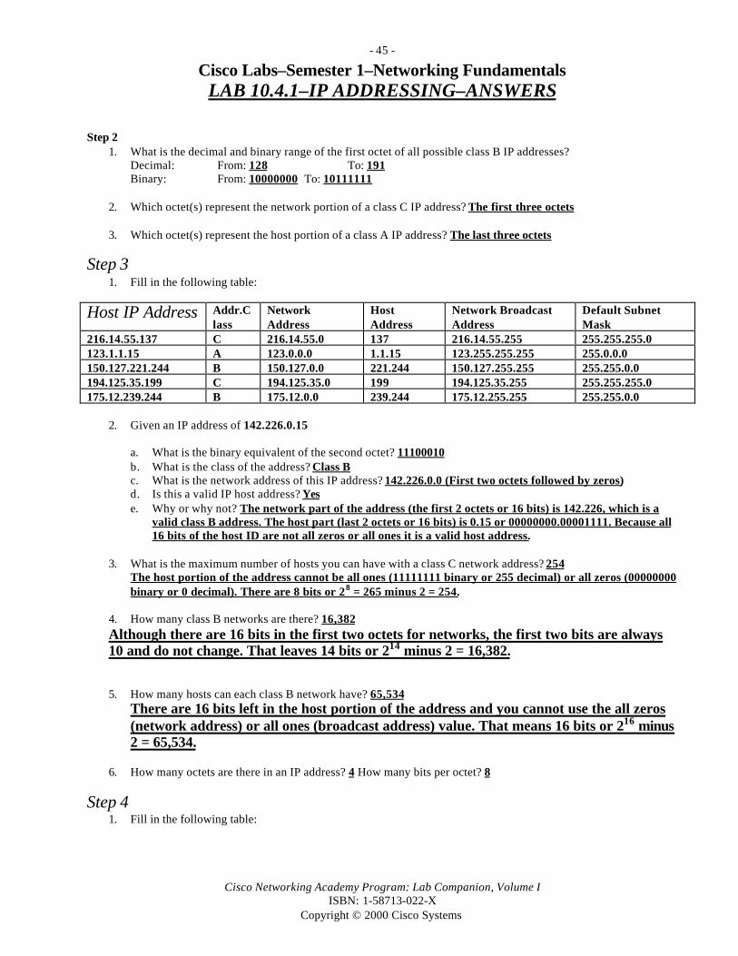
Cisco Labs–Semester 1–Networking FundamentalsLAB 10.4.1–IP ADDRESSING–ANSWERS
Step 21. What is the decimal and binary range of the first octet of all possible class B IP addresses?
Decimal: From: 128 To: 191Binary: From: 10000000 To: 10111111
2. Which octet(s) represent the network portion of a class C IP address? The first three octets
3. Which octet(s) represent the host portion of a class A IP address? The last three octets
Step 31. Fill in the following table:
Host IP Address Addr.Class
NetworkAddress
HostAddress
Network BroadcastAddress
Default SubnetMask
216.14.55.137 C 216.14.55.0 137 216.14.55.255 255.255.255.0123.1.1.15 A 123.0.0.0 1.1.15 123.255.255.255 255.0.0.0150.127.221.244 B 150.127.0.0 221.244 150.127.255.255 255.255.0.0194.125.35.199 C 194.125.35.0 199 194.125.35.255 255.255.255.0175.12.239.244 B 175.12.0.0 239.244 175.12.255.255 255.255.0.0
2. Given an IP address of 142.226.0.15
a. What is the binary equivalent of the second octet? 11100010b. What is the class of the address? Class Bc. What is the network address of this IP address? 142.226.0.0 (First two octets followed by zeros)d. Is this a valid IP host address? Yese. Why or why not? The network part of the address (the first 2 octets or 16 bits) is 142.226, which is a
valid class B address. The host part (last 2 octets or 16 bits) is 0.15 or 00000000.00001111. Because all16 bits of the host ID are not all zeros or all ones it is a valid host address.
3. What is the maximum number of hosts you can have with a class C network address? 254The host portion of the address cannot be all ones (11111111 binary or 255 decimal) or all zeros (00000000binary or 0 decimal). There are 8 bits or 28 = 265 minus 2 = 254.
4. How many class B networks are there? 16,382Although there are 16 bits in the first two octets for networks, the first two bits are always10 and do not change. That leaves 14 bits or 214 minus 2 = 16,382.
5. How many hosts can each class B network have? 65,534There are 16 bits left in the host portion of the address and you cannot use the all zeros(network address) or all ones (broadcast address) value. That means 16 bits or 216 minus2 = 65,534.
6. How many octets are there in an IP address? 4 How many bits per octet? 8
Step 41. Fill in the following table:

- 46 -
Cisco Networking Academy Program: Lab Companion, Volume IISBN: 1-58713-022-X
Copyright © 2000 Cisco Systems
IP HostAddress
Valid Address?(Yes/No)
Why or Why Not
150.100.255.255 No 150.100.0.0.is a Class B network. This is a broadcast address for aClass B (host portion 3rd and 4 th octets is all ones) and cannot be usedfor a host address.
175.100.255.18 Yes 175.100.0.0 is a Class B network. The host portion is the 3rd and 4th
octets (16 bits taken together) 11111111.00010010 and is not all zerosor all ones. It is valid even though the 3rd octet is all ones.
195.234.253.0 No 195.234.253.0 is a Class C network. This is the network address or IDfor this network and cannot be used for a host address because all thehost bits are zeros.
100.0.0.23 Yes 100.0.0.0 is a Class A network. The host portion of the address is the2nd, 3rd, and 4th octets (24 bits taken together)00000000.00000000.00010111 and is not all zeros or all ones. It is valideven though the 2nd and 3rd octets are all zeros.
188.258.221.176 No This would be a Class B network but is invalid because the 2nd octet isgreater than 255. No octet can be greater than 255 (all ones) in any IPaddress (network or host).
127.34.25.189 No This would be a Class A network, but is invalid because 127 can’t beused in the first octet because it is reserved for diagnostic testing.
224.156.217.73 No This is a Class D network, and Class D is reserved for multicasting andcan’t be used as a commercial IP address.

- 47 -
Cisco Networking Academy Program: Lab Companion, Volume IISBN: 1-58713-022-X
Copyright © 2000 Cisco Systems
Cisco Labs–Semester 1–Networking FundamentalsLAB 10.6.6–SUBNET MASK 1–CLASS C with 2 SUBNETS–ANSWERS
Step 51. Fill in the table below and answer the following questions:
Subnet No. Subnet BitsBorrowedBinary Value
Subnet BitsDecimal andSubnet No.
Host Bits Possible BinaryValues (Range) (6 Bits)
Subnet/HostDecimal Range
Use?
1st Subnet 000 0(197.15.22.0)
00000–11111 0–31 NO
2nd Subnet 001 32(197.15.22.32)
00000–11111 32–63 YES
3rd Subnet 010 64(197.15.22.64)
00000–11111 64–95 YES
4th Subnet 011 96(197.15.22.96)
00000–11111 96–127 YES
5th Subnet 100 128(197.15.22.128)
00000–11111 128–159 YES
6th Subnet 101 160(127.15.22.160)
00000–11111 160–191 YES
7th Subnet 110 192(127.15.22.192)
00000–11111 192–223 YES
8th Subnet 111 224(127.15.22.224)
00000–11111 224–255 NO
NOTES:____________________________________________________________________________________________________________________________________________________________________________________________________________________________________________________________________________________________________________________________________________________________________________________________________________________________________________________________________________________________________________________________________________________________________________________________________________________________________________________________________________________________________________________________________________________________________________________________________________________________________________________________________________________________________________________________________________________________________________________________________________
- 48 -
Cisco Networking Academy Program: Lab Companion, Volume IISBN: 1-58713-022-X
Copyright © 2000 Cisco Systems
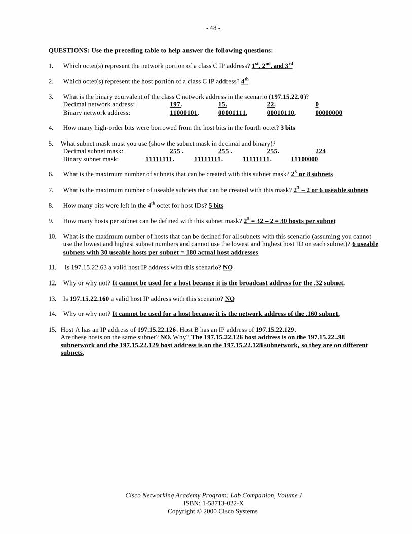
QUESTIONS: Use the preceding table to help answer the following questions:
1. Which octet(s) represent the network portion of a class C IP address? 1st, 2nd, and 3rd
2. Which octet(s) represent the host portion of a class C IP address? 4th
3. What is the binary equivalent of the class C network address in the scenario (197.15.22.0)?Decimal network address: 197. 15. 22. 0Binary network address: 11000101. 00001111. 00010110. 00000000
4. How many high-order bits were borrowed from the host bits in the fourth octet? 3 bits
5. What subnet mask must you use (show the subnet mask in decimal and binary)?Decimal subnet mask: 255 . 255 . 255. 224Binary subnet mask: 11111111. 11111111. 11111111. 11100000
6. What is the maximum number of subnets that can be created with this subnet mask? 23 or 8 subnets
7. What is the maximum number of useable subnets that can be created with this mask? 23 – 2 or 6 useable subnets
8. How many bits were left in the 4th octet for host IDs? 5 bits
9. How many hosts per subnet can be defined with this subnet mask? 25 = 32 – 2 = 30 hosts per subnet
10. What is the maximum number of hosts that can be defined for all subnets with this scenario (assuming you cannotuse the lowest and highest subnet numbers and cannot use the lowest and highest host ID on each subnet)? 6 useablesubnets with 30 useable hosts per subnet = 180 actual host addresses
11. Is 197.15.22.63 a valid host IP address with this scenario? NO
12. Why or why not? It cannot be used for a host because it is the broadcast address for the .32 subnet.
13. Is 197.15.22.160 a valid host IP address with this scenario? NO
14. Why or why not? It cannot be used for a host because it is the network address of the .160 subnet.
15. Host A has an IP address of 197.15.22.126 . Host B has an IP address of 197.15.22.129 .Are these hosts on the same subnet? NO. Why? The 197.15.22.126 host address is on the 197.15.22..98subnetwork and the 197.15.22.129 host address is on the 197.15.22.128 subnetwork, so they are on differentsubnets.
- 49 -
Cisco Networking Academy Program: Lab Companion, Volume IISBN: 1-58713-022-X
Copyright © 2000 Cisco Systems
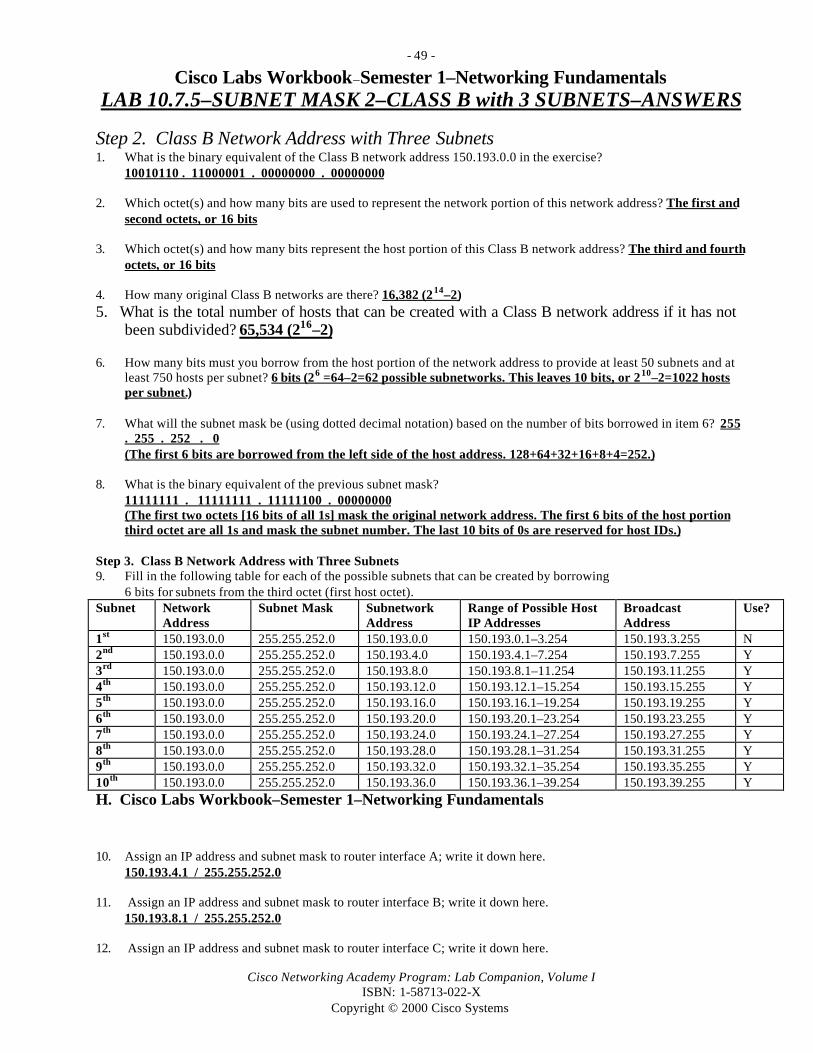
Cisco Labs Workbook–Semester 1–Networking FundamentalsLAB 10.7.5–SUBNET MASK 2–CLASS B with 3 SUBNETS–ANSWERS
Step 2. Class B Network Address with Three Subnets1. What is the binary equivalent of the Class B network address 150.193.0.0 in the exercise?
10010110 . 11000001 . 00000000 . 00000000
2. Which octet(s) and how many bits are used to represent the network portion of this network address? The first andsecond octets, or 16 bits
3. Which octet(s) and how many bits represent the host portion of this Class B network address? The third and fourthoctets, or 16 bits
4. How many original Class B networks are there? 16,382 (214–2)5. What is the total number of hosts that can be created with a Class B network address if it has not
been subdivided? 65,534 (216–2)
6. How many bits must you borrow from the host portion of the network address to provide at least 50 subnets and atleast 750 hosts per subnet? 6 bits (26 =64–2=62 possible subnetworks. This leaves 10 bits, or 210–2=1022 hostsper subnet.)
7. What will the subnet mask be (using dotted decimal notation) based on the number of bits borrowed in item 6? 255. 255 . 252 . 0(The first 6 bits are borrowed from the left side of the host address. 128+64+32+16+8+4=252.)
8. What is the binary equivalent of the previous subnet mask?11111111 . 11111111 . 11111100 . 00000000(The first two octets [16 bits of all 1s] mask the original network address. The first 6 bits of the host portionthird octet are all 1s and mask the subnet number. The last 10 bits of 0s are reserved for host IDs.)
Step 3. Class B Network Address with Three Subnets9. Fill in the following table for each of the possible subnets that can be created by borrowing
6 bits for subnets from the third octet (first host octet).Subnet Network
AddressSubnet Mask Subnetwork
AddressRange of Possible HostIP Addresses
BroadcastAddress
Use?
1st 150.193.0.0 255.255.252.0 150.193.0.0 150.193.0.1–3.254 150.193.3.255 N2nd 150.193.0.0 255.255.252.0 150.193.4.0 150.193.4.1–7.254 150.193.7.255 Y3rd 150.193.0.0 255.255.252.0 150.193.8.0 150.193.8.1–11.254 150.193.11.255 Y4th 150.193.0.0 255.255.252.0 150.193.12.0 150.193.12.1–15.254 150.193.15.255 Y5th 150.193.0.0 255.255.252.0 150.193.16.0 150.193.16.1–19.254 150.193.19.255 Y6th 150.193.0.0 255.255.252.0 150.193.20.0 150.193.20.1–23.254 150.193.23.255 Y7th 150.193.0.0 255.255.252.0 150.193.24.0 150.193.24.1–27.254 150.193.27.255 Y8th 150.193.0.0 255.255.252.0 150.193.28.0 150.193.28.1–31.254 150.193.31.255 Y9th 150.193.0.0 255.255.252.0 150.193.32.0 150.193.32.1–35.254 150.193.35.255 Y10th 150.193.0.0 255.255.252.0 150.193.36.0 150.193.36.1–39.254 150.193.39.255 YH. Cisco Labs Workbook–Semester 1–Networking Fundamentals
10. Assign an IP address and subnet mask to router interface A; write it down here.150.193.4.1 / 255.255.252.0
11. Assign an IP address and subnet mask to router interface B; write it down here.150.193.8.1 / 255.255.252.0
12. Assign an IP address and subnet mask to router interface C; write it down here.

- 50 -
Cisco Networking Academy Program: Lab Companion, Volume IISBN: 1-58713-022-X
Copyright © 2000 Cisco Systems
150.193.12.1 / 255.255.252.0
13. Assign a host IP address to host X on subnet A, and assign an IP address to host Z on subnet C (answers may vary).Describe the steps (using ANDing) for the process of sending an IP packet from host X to host Z through the router.Use the information from the previous diagram and in Lab 1.10 to help assign IP addresses and subnet masks. HostX = 150.193.4.2 (4.1 was used for the router interface on subnet A). Host Z = 150.193.12.2 (12.1 was used forthe router interface on subnet C). Host X compares (ANDs) the subnet mask to its own IP address and comesup with its own network/subnet address of 150.193.4.0. It then compares the subnet mask to the IP address ofthe destination host (150.193.12.2) and comes up with the network/subnet address of the target network(150.193.12.0). Because the two do not match, host X must assume that the destination host is not on itsnetwork, and it sends the packet to its “default gateway,” or the nearside port of the router (interface A). Therouter goes through the same process on its incoming interface A and determines that network 150.193.12.2 ison its C interface. The router forwards the packet to interface C; because the router also knows the MACaddress of hosts directly attached to its interfaces such as host Z, it forwards the packet to the 150.193.12.0network/subnet LAN, and host Z picks it up.
14. What is the result of the ANDing process for host X?Decimal host X IP address: 150 . 193 . 4 . 2Binary host X IP address: 10010110 . 11000001 . 00000100 . 00000010Binary subnet mask: 11111111 . 11111111 . 11111100 . 00000000Binary ANDing result: 10010110 . 11000001 . 00000100 . 00000000Decimal ANDing result: 150 . 193 . 4 . 0
15. What is the result of the ANDing process for host Z?Decimal host Z IP address: 150 . 193 . 12 . 2Binary host Z IP address: 10010110 . 11000001 . 00001100 . 00000010
Binary subnet mask: 11111111 . 11111111 . 11111100 . 00000000Binary ANDing result: 10010110 . 11000001 . 00001100 . 00000000Decimal ANDing result: 150 . 193 . 12 . 0
16. The decimal ANDing result from question 14 is the network/subnet that host X is on. The result from question 15 isthe network/subnet that host Z is on. Are host X and host Z on the same network/subnet? NO
17. What will host X now do with the packet? Because the destination host Z is not on the host X local-areanetwork, host X will send the packet to the default gateway, which is the IP address of Interface A on therouter.

- 51 -
Cisco Networking Academy Program: Lab Companion, Volume IISBN: 1-58713-022-X
Copyright © 2000 Cisco Systems
18. Fill in the blanks in the following diagram with the correct network and IP addresses.
Router Interface A Router Interface CIP: 150.193.4.1 IP: 150.193.12.1
LAN A Router Interface B LAN CSubnet A Address: IP: 150.193.8.1 Subnet C Address:150.193.4.0 150.193.12.0
LAN BSubnet B Address:150.193.8.0
Host X IP: 150.193.4.2 Host Z IP: 150.193.12.2
A B C
HUB A HUB C
Host ZHost X
Router with 3Three LAN interfaces (A, B, and
HUB B
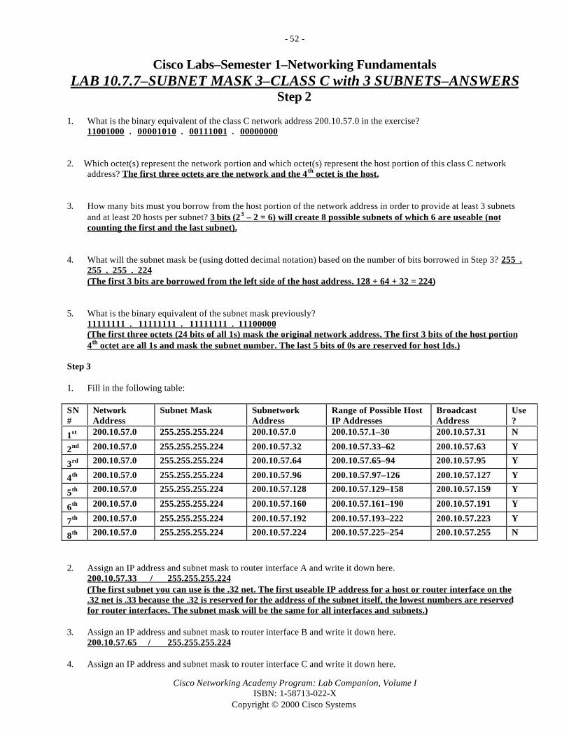
- 52 -
Cisco Networking Academy Program: Lab Companion, Volume IISBN: 1-58713-022-X
Copyright © 2000 Cisco Systems
Cisco Labs–Semester 1–Networking FundamentalsLAB 10.7.7–SUBNET MASK 3–CLASS C with 3 SUBNETS–ANSWERS
Step 2
1. What is the binary equivalent of the class C network address 200.10.57.0 in the exercise?11001000 . 00001010 . 00111001 . 00000000
2. Which octet(s) represent the network portion and which octet(s) represent the host portion of this class C networkaddress? The first three octets are the network and the 4 th octet is the host.
3. How many bits must you borrow from the host portion of the network address in order to provide at least 3 subnetsand at least 20 hosts per subnet? 3 bits (23 – 2 = 6) will create 8 possible subnets of which 6 are useable (notcounting the first and the last subnet).
4. What will the subnet mask be (using dotted decimal notation) based on the number of bits borrowed in Step 3? 255 .255 . 255 . 224(The first 3 bits are borrowed from the left side of the host address. 128 + 64 + 32 = 224)
5. What is the binary equivalent of the subnet mask previously?11111111 . 11111111 . 11111111 . 11100000(The first three octets (24 bits of all 1s) mask the original network address. The first 3 bits of the host portion4th octet are all 1s and mask the subnet number. The last 5 bits of 0s are reserved for host Ids.)
Step 3
1. Fill in the following table:
SN#
NetworkAddress
Subnet Mask SubnetworkAddress
Range of Possible HostIP Addresses
BroadcastAddress
Use?
1st 200.10.57.0 255.255.255.224 200.10.57.0 200.10.57.1–30 200.10.57.31 N
2nd 200.10.57.0 255.255.255.224 200.10.57.32 200.10.57.33–62 200.10.57.63 Y
3rd 200.10.57.0 255.255.255.224 200.10.57.64 200.10.57.65–94 200.10.57.95 Y
4th 200.10.57.0 255.255.255.224 200.10.57.96 200.10.57.97–126 200.10.57.127 Y
5th 200.10.57.0 255.255.255.224 200.10.57.128 200.10.57.129–158 200.10.57.159 Y
6th 200.10.57.0 255.255.255.224 200.10.57.160 200.10.57.161–190 200.10.57.191 Y
7th 200.10.57.0 255.255.255.224 200.10.57.192 200.10.57.193–222 200.10.57.223 Y
8th 200.10.57.0 255.255.255.224 200.10.57.224 200.10.57.225–254 200.10.57.255 N
2. Assign an IP address and subnet mask to router interface A and write it down here.200.10.57.33 / 255.255.255.224(The first subnet you can use is the .32 net. The first useable IP address for a host or router interface on the.32 net is .33 because the .32 is reserved for the address of the subnet itself, the lowest numbers are reservedfor router interfaces. The subnet mask will be the same for all interfaces and subnets.)
3. Assign an IP address and subnet mask to router interface B and write it down here.200.10.57.65 / 255.255.255.224
4. Assign an IP address and subnet mask to router interface C and write it down here.

- 53 -
Cisco Networking Academy Program: Lab Companion, Volume IISBN: 1-58713-022-X
Copyright © 2000 Cisco Systems
200.10.57.97 / 255.255.255.224
5. Assign a host IP address to Host X on Subnet A and assign an IP address to Host Z onSubnet C (answers might vary). Describe the steps (using ANDing) in the process of sending an IP packet from HostX to Host Z through the router. Host X = 200.10.57.34 (.33 was used for the router interface on subnet A), Host Z= 200.10.57.98 (.97 was used for the router interface on subnet C). Host X compares (ANDs) the subnet maskto its own IP address and comes up with its own network/subnet address of 200.10.57.32. It then compares thesubnet mask to the IP address of the destination host (200.10.57.98) and comes up with the network/subnetaddress of the target network (200.10.57.96). Because the two do not match, Host X must assume that thedestination host is not on its network, and it sends the packet to its “Default Gateway” or the nearside port ofthe router. The router goes through the same process on its incoming interface A and determines that network200.10.57.96 is on its C interface. The router forwards the packet to interface C and because the router alsoknows the MAC address of hosts directly attached to its interfaces such as Host Z, it forwards the packet tothe 200.10.57.96 network/subnet LAN and Host Z picks it up.
6. What is the result of the ANDing process for Host X?Decimal Host X IP addr: 200 . 10 . 57 . 34Binary Host X IP addr: 11001000 . 00001010 . 00111001 . 00100110Binary Subnet Mask: 11111111 . 11111111 . 11111111 . 11100000Binary ANDing Result: 11001000 . 00001010 . 00111001 . 00100000Decimal ANDing Result: 200 . 10 . 57 . 32
7. What is the result of the ANDing process for Host Z?Decimal Host Z IP addr: 200 . 10 . 57 . 98Binary Host Z IP addr: 11001000 . 00001010 . 00111001 . 01100110Binary Subnet Mask: 11111111 . 11111111 . 11111111 . 11100000Binary ANDing Result: 11001000 . 00001010 . 00111001 . 00100000Decimal ANDing Result: 200 . 10 . 57 . 96
8. The decimal ANDing result from question 11 is the network/subnet that Host X is on. The result from question 12 isthe network/subnet that Host Z is on. Are Host X and Host Z on the same network/subnet? NO
9. What will Host X do with the packet? Because the destination Host Z is not on the Host X local-area network,Host X will send the packet to the “Default Gateway,” which is the IP address of Interface A on the router.

- 54 -
Cisco Networking Academy Program: Lab Companion, Volume IISBN: 1-58713-022-X
Copyright © 2000 Cisco Systems
10. When the router receives the packet from Host X and compares its interface A IP address and the destination addressfor Host Z with the subnet mask, which router interface will it send the packet out of to get the packet to Host Z?Interface C
Router Interface ARouter Interface C
IP: 200.10.57.33 IP:200.10.57.97
LAN A Router Interface B LANCSubnet A Address IP: 200.10.57.65 Subnet CAddress200.10.57.32
200.10.57.96
LAN BSubnet B Address200.10.57.64
Host X IP: 200.10.57.34 HostZ IP: 200.10.57.98
A B C
HUB A
HUB B
HUB C
Host ZHost X
Router with 3 LAN interfaces (A, B, and C)

- 55 -
Cisco Networking Academy Program: Lab Companion, Volume IISBN: 1-58713-022-X
Copyright © 2000 Cisco Systems
Cisco Labs–Semester 1–Networking FundamentalsLAB 11.9.1–PROTOCOL INSPECTOR and ARP–ANSWERS
1. Open Protocol Inspector (or equivalent) software. Students should be experienced with thisstep from the earlier lab.
2. Go to detail view. What do you see? A brand-new window, with the monitoring graph, andmany more icons indicating the powerful capabilities of this software.
3. Start a capture. What happens? The monitor graph indicates any network traffic that isdetected. It might be somewhat flat (“quiet”) depending on your network’s configuration.
4. Open an MS-DOS window. In Windows, go to START, PROGRAMS, MS-DOS PROMPT.
5. Using arp -a examine the contents of the ARP table. What do you see? You should see thecontents of your PC’s ARP table, which includes MAC addresses and their associated IPaddresses.
6. Using arp -d a.b.c.d delete all entries in the ARP table. Use arp -a to re-examine the ARP table.What has happened? The ARP table should be empty.
7. Use ping a.b.c.d to trigger an ARP frame. What happens? Ping your own machine oranother machine on the network. The ping should be successful, and you should notice specificactivity on the monitoring graph.
8. Stop the capture. What happens? The monitor graph indicates you are no longer capturingframes. Now you will use the database (the detail view) to study the ARP in detail.
9. Study the ARP frames, ping frames, and statistics using various views, especially the detail view.
Describe the various views and what you learned about ARP. This is an excellent opportunity
to take various views of two important network protocols: ARP and ping. The graphs
provide an interesting look at the frames involved in these network processes.
10. Start another capture to examine the network you are on.
11. Use the network for a minute or so (sending e-mails, requesting web pages, and so on) over some
period of time (say two minutes) and see in detail how many ARP frames occur. Are any
occurring? If so, why? On an active network there will be ARPs occurring for various
reasons: workstations logging on and off, other protocols requiring ARP information.

- 56 -
Cisco Networking Academy Program: Lab Companion, Volume IISBN: 1-58713-022-X
Copyright © 2000 Cisco Systems
Reflection:Why is ARP necessary for LANs to function? ARP is necessary for local delivery of informationon a LAN. Having the destination IP address is not sufficient; the destination MAC is required aswell. ARP indicates the MAC address–IP address bindings.
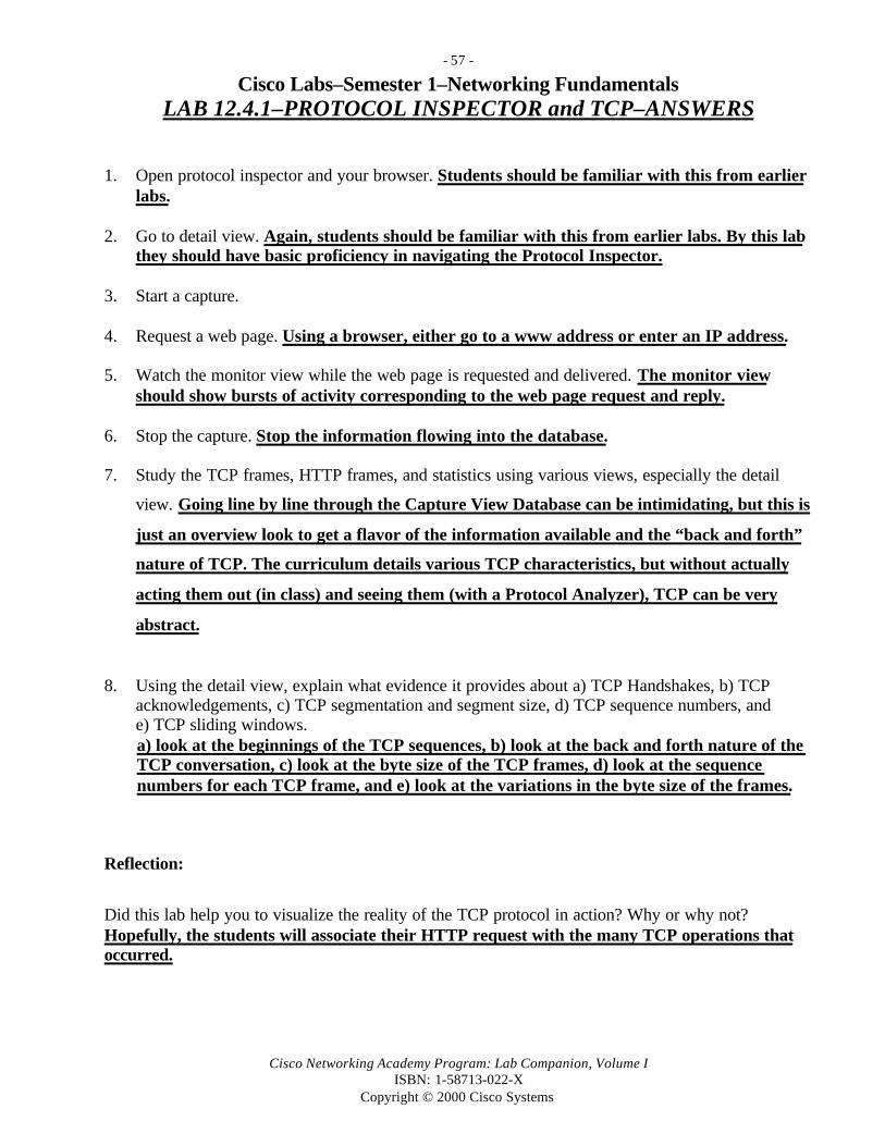
- 57 -
Cisco Networking Academy Program: Lab Companion, Volume IISBN: 1-58713-022-X
Copyright © 2000 Cisco Systems
Cisco Labs–Semester 1–Networking FundamentalsLAB 12.4.1–PROTOCOL INSPECTOR and TCP–ANSWERS
1. Open protocol inspector and your browser. Students should be familiar with this from earlierlabs.
2. Go to detail view. Again, students should be familiar with this from earlier labs. By this labthey should have basic proficiency in navigating the Protocol Inspector.
3. Start a capture.
4. Request a web page. Using a browser, either go to a www address or enter an IP address.
5. Watch the monitor view while the web page is requested and delivered. The monitor viewshould show bursts of activity corresponding to the web page request and reply.
6. Stop the capture. Stop the information flowing into the database.
7. Study the TCP frames, HTTP frames, and statistics using various views, especially the detail
view. Going line by line through the Capture View Database can be intimidating, but this is
just an overview look to get a flavor of the information available and the “back and forth”
nature of TCP. The curriculum details various TCP characteristics, but without actually
acting them out (in class) and seeing them (with a Protocol Analyzer), TCP can be very
abstract.
8. Using the detail view, explain what evidence it provides about a) TCP Handshakes, b) TCPacknowledgements, c) TCP segmentation and segment size, d) TCP sequence numbers, ande) TCP sliding windows.a) look at the beginnings of the TCP sequences, b) look at the back and forth nature of the TCP conversation, c) look at the byte size of the TCP frames, d) look at the sequence numbers for each TCP frame, and e) look at the variations in the byte size of the frames.
Reflection:
Did this lab help you to visualize the reality of the TCP protocol in action? Why or why not?Hopefully, the students will associate their HTTP request with the many TCP operations thatoccurred.

- 58 -
Cisco Networking Academy Program: Lab Companion, Volume IISBN: 1-58713-022-X
Copyright © 2000 Cisco Systems
Cisco Labs–Semester 2–Router ConfigurationLAB 2.2.2–ROUTER CHARACTERISTICS–ANSWERS
Step 1
1. Examine the router. What is the model number? Cisco 2514 (answers will vary)
2. Do you see a console port? Yes What port is it connected to on the console terminal (PCworkstation)? 9-pin serial COM1 port with an RJ45 converter
3. What type of cable is the console cable? Is it a roll-over, cross-connect, or straight-throughcable? The cable is a roll-over (pin 1 to pin 8, pin 2 to pin 7, and so on).
Step 24. Fill in the following table. (These are examples.)
RouterInterface/PortIdentifier
Cable Type/Connector Device and Port to Which the Cable IsConnected
Console Roll-over, RJ45 PC serial port com1 (9-Pin)AUX None Used for modem with remote dial-inE0 (AUI0) CAT 5 Unshielded Twisted
Pair (UTP) and 8-pin RJ45or DB15
Ethernet hub or switch
BRI0 Not used, RJ45 Basic Rate Interface ISDNTo0 (DB9) Not used, connector female Token Ring interfaceS0 (synchronous) Serial cable DB60 to V.35 WAN link connection to other routerS1 (synchronous) Not used WAN link connection
Step 35. Fill in the following table with the information indicated.
Configuration Option Current Setting(s)COM port Direct to COM1Bits per second 9600Data bits 8Parity NoneStop bits 2Flow control Hardware

- 59 -
Cisco Networking Academy Program: Lab Companion, Volume IISBN: 1-58713-022-X
Copyright © 2000 Cisco Systems
Step 4. Display IOS version and other important information related to RAM, NVRAM, andFlash memory with the show version command (refer to the show version output listedfollowing the questions).
6. What is the IOS version? Version 11.1(5)7. What is the name of the system image (IOS) file? flash:igs-j-l.111-5
8. From where was the router IOS image booted? Flash memory9. What type of processor (CPU) and how much RAM does this router have? cisco 2500 (68030)processor (revision N) with 6144K/2048K bytes of memory10. How many Ethernet interfaces does this router have? 1 Ethernet/IEEE 802.3 interface11. How many serial interfaces? 2 serial network interfaces12. The router backup configuration file is stored in Non-Volatile Random Access Memory
(NVRAM). How much NVRAM does this router have? 32K bytes of non-volatileconfiguration memory
13. The router operating system (IOS) is stored in Flash memory. How much flash memory doesthis router have? 8192K bytes of processor board system Flash (read-only)
Results of show version command (output generated by a Cisco 2501 router)Lab-D> show versionCisco Internetwork Operating System SoftwareIOS (tm) 3000 Software (IGS-J-L), Version 11.1(5), RELEASE SOFTWARE (fc1)Copyright (c) 1986-1996 by cisco Systems, Inc.Compiled Mon 05-Aug-96 11:48 by mkamsonImage text-base: 0x0303794C, data-base: 0x00001000
ROM: System Bootstrap, Version 11.0(10c), SOFTWAREROM: 3000 Bootstrap Software (IGS-BOOT-R), Version 11.0(10c), RELEASE SOFTWARE (fc1)
Router uptime is 15 minutesSystem restarted by power-onSystem image file is “flash:igs-j-l.111-5”, booted via flash
cisco 2500 (68030) processor (revision N) with 6144K/2048K bytes of memory.Processor board ID 05645767, with hardware revision 00000000Bridging software.SuperLAT software copyright 1990 by Meridian Technology Corp).X.25 software, Version 2.0, NET2, BFE and GOSIP compliant.TN3270 Emulation software (copyright 1994 by TGV Inc).1 Ethernet/IEEE 802.3 interface.2 Serial network interfaces.32K bytes of non-volatile configuration memory.8192K bytes of processor board System flash (Read ONLY)
Configuration register is 0x2102

- 60 -
Cisco Networking Academy Program: Lab Companion, Volume IISBN: 1-58713-022-X
Copyright © 2000 Cisco Systems
Cisco Labs–Semester 2–Router ConfigurationLAB 2.2.3.1–ROUTER LAB SETUP–ANSWERS
1. Examine the cables and connections on the routers, and document the connections in
this table:
From Router Name Interface To Router Name InterfaceLab-A S0 (DCE) Lab-B S1 (DTE)Lab-B S0 (DCE) Lab-C S1 (DTE)Lab-C S0 (DCE) Lab-D S1 (DTE)
2. Record the router Ethernet interfaces in use and which hub (or switch) they attach to in
this table:
From Router Name Router Interface To Which Ethernet DeviceLab-A E0 Hub # 1Lab-A E1 SwitchLab-B E0 Hub # 2Lab-C E0 Hub # 3Lab-D E0 Hub # 4Lab-E E0 Hub # 4
3. Indicate which Ethernet device each workstation connects to in this table:
From Workstation To Which Ethernet DeviceWS-1 SwitchWS-2 SwitchWS-3 Hub # 1WS-4 Hub # 1WS-5 Hub # 2WS-6 Hub # 2WS-7 Hub # 3WS-8 Hub # 3WS-9 Hub # 4WS-10 Hub # 4
4. What type of cable is the console cable? Roll-over (pin 1 to pin 8, pin 2 to pin 7, and so on)
5. Are the link lights for the switch, the hubs, and the Network Interface Cards (NICs) in theworkstations on? Yes Are the OK lights on the back of the routers on? Yes
6. Draw your lab diagram.

- 61 -
Cisco Networking Academy Program: Lab Companion, Volume IISBN: 1-58713-022-X
Copyright © 2000 Cisco Systems
The lab diagrams might vary, depending on what type of equipment is present. Focus
should be on the physical components and on the communications links between them,
including LAN (Ethernet) and WAN (serial) connections.

- 62 -
Cisco Networking Academy Program: Lab Companion, Volume IISBN: 1-58713-022-X
Copyright © 2000 Cisco Systems
Cisco Labs–Semester 2–Router ConfigurationLAB 2.2.3.2–ROUTER LAB CONFIGURATION–ANSWERS
1. Fill in the table below with IP interface information for each of the five routers.
Cisco Lab Router IP Configuration (answers from router diagram—your answers may vary)
Router Name Lab-A Lab-B Lab-C Lab-D Lab-E
Model Number 2514 2503 2503 2501 2501
Interface E0IP Address
192.5.5.1 219.17.100.1 223.8.151.1 210.93.105.1 210.93.105.2
Interface E0Subnet Mask
255.255.255.0 255.255.255.0 255.255.255.0 255.255.255.0 255.255.255.0
Interface E1IP Address
205.7.5.1 Not Present Not Present Not Present Not Present
Interface E1Subnet Mask
255.255.255.0 Not Present Not Present Not Present Not Present
Interface S0IP Address
201.100.11.1 199.6.13.1 204.204.7.1 Not Used Not Used
Interface S0Subnet Mask
255.255.255.0 255.255.255.0 255.255.255.0 Not Used Not Used
Interface S0* Clock Rate
56000 56000 56000 Not Used Not Used
Interface S1IP Address
Not Used 201.100.11.2 196.6.13.2 204.204.7.2 Not Used
Interface S1Subnet Mask
Not Used 255.255.255.0 255.255.255.0 255.255.255.0 Not Used
OtherInterface(s)
Console,AUX
ISDN BRI0,Console,AUX
ISDN BRI0,Console,AUX
Console,AUX
Console,AUX
* Note: Clock rate must be set on the DCE end (S0) of the WAN link between routers.
2. With the information gathered from the show running-config command at router Lab-A,
answer the following questions:
a. What is the routing protocol used? RIP (Routing Information Protocol)
b. What are the networks that are directly connected to the interfaces?
192.5.5.0, 205.7.5.0, 201.100.11.0
c. What is the clock rate of interface S0 on router Lab-A? 56000
d. What is the password for Telnet VTY lines 0 through 4? cisco

- 63 -
Cisco Networking Academy Program: Lab Companion, Volume IISBN: 1-58713-022-X
Copyright © 2000 Cisco Systems
3. Fill in the IP configuration with information obtained from each workstation.
Workstation IP Address ConfigurationWorkstation#
WorkstationIP Address
Workstation SubnetMask
Default Gateway IPAddress
1 192.5.5.11 255.255.255.0 192.5.5.12 192.5.5.12 255.255.255.0 192.5.5.13 205.7.5.11 255.255.255.0 205.7.5.14 205.7.5.12 255.255.255.0 205.7.5.15 219.17.100.11 255.255.255.0 219.17.100.16 219.17.100.12 255.255.255.0 219.17.100.17 223.8.151.11 255.255.255.0 223.8.151.18 223.8.151.12 255.255.255.0 223.8.151.19 210.93.105.11 255.255.255.0 210.93.105.110 210.93.105.12 255.255.255.0 210.93.105.2
4. Was the ping from router Lab-A to Lab-B successful? Yes. If not, check connections andobtain assistance from instructor or lab assistant.
5. Was the ping from router Lab-A to Lab-B successful? Yes. If not, check connections andobtain assistance from instructor or lab assistant.
6. Steps to configure the routers for the standard lab setup (optional)These are abbreviated instructions. You will need help from the instructor or labassistant if you are not familiar with Cisco IOS configuration commands.
From the PC that is connected to the console interface of a router, start HyperTerminal.Create a session that connects the PC’s serial port to the router’s console interface. Get to userexec mode (Router>). If the System Configuration dialog appears, press Ctrl-C to exit thedialog.
A. Router Lab-A (2514) Basic Configuration CommandsThe following set of IOS commands can be used to configure router Lab-A. Explanations areprovided for each command. Use these commands and the information provided in the table ofanswers for question 1, Cisco Lab Router IP Configuration, to configure the remaining fourrouters. The exact commands required to configure the other routers will vary somewhat,depending on which interfaces are in use and what IP addresses should be set on those interfaces.

- 64 -
Cisco Networking Academy Program: Lab Companion, Volume IISBN: 1-58713-022-X
Copyright © 2000 Cisco Systems
Router Lab-A (2514) Basic Configuration Commands (other routers will vary)Step Description/Explanation Router Command
PromptIOS Command
Enable privileged mode Router> EnableConfigure (the router) fromterminal (keyboard)
Router# Config T
Name Router Lab-A
(the prompt will change)
Router(config)# Hostname Lab-A
Set privileged mode encrypted(secret) password to class
Lab-A(config)# Enable secret class
Set privileged mode text password(optional)
Lab-A(config)# Enable password cisco
Disable DNS lookup Lab-A(config)# No ip domain-lookup
Select E0 interface Lab-A(config)# Interface Ethernet0
Provide description for E0(optional on any interface)
Lab-A(config-if)# Description connected to LAN A
Set E0 IP address and subnet mask Lab-A(config-if)# Ip address 192.5.5.1 255.255.255.0Bring interface E0 up Lab-A(config-if)# No shutdown
Select E1 interface Lab-A(config)# Interface Ethernet1
Set E1 IP address and subnet mask Lab-A(config-if)# Ip address 205.7.5.1 255.255.255.0Bring interface E0 up Lab-A(config-if)# No shutdown
Select S0 interface Lab-A(config-if)# Interface Serial0
Set S0 IP address and subnet mask Lab-A(config-if)# ip address 201.100.11.1 255.255.255.0Set IGRP bandwidth metric Lab-A(config-if)# Bandwidth 56Set DCE clock synch at 56000 Lab-A(config-if)# Clock rate 56000Bring interface S0 up Lab-A(config-if)# no shutdown
!Select S1 interface (not
used)
Lab-A(config-if)# Interface Serial1
Set no IP address for S1 Lab-A(config-if)# No ip addressAdministratively shut down S1 Lab-A(config-if)# Shutdown
Exit interface config mode Lab-A(config-if)# Exit
Start RIP routing
protocol
Lab-A(config)# Router rip
Specify directly connected networkfor routing updates
Lab-A(config-router)# Network 192.5.5.0
Specify directly connected networkfor routing updates
Lab-A(config-router)# Network 205.7.5.0

- 65 -
Cisco Networking Academy Program: Lab Companion, Volume IISBN: 1-58713-022-X
Copyright © 2000 Cisco Systems
Specify directly connected networkfor routing updates
Lab-A(config-router)# Network 201.100.11.0
Exit router config mode Lab-A(config-router)# Exit
Router Lab-A (2514) Basic Configuration Commands—ContinuedEnable browser management Lab-A(config)# Ip http server
Define router host name table N/A N/ASpecify host table entry for Lab-A(with interface IP addresses)
Lab-A(config)# ip host Lab-A 192.5.5.1 205.7.5.1201.100.11.1
Specify host table entry for Lab-B(with interface IP addresses)
Lab-A(config)# ip host Lab-B 219.17.100.1 199.6.13.1201.100.11.2
Specify host table entry for Lab-C(with interface IP addresses)
Lab-A(config)# ip host Lab-C 223.8.151.1 204.204.7.1199.6.13.2
Specify host table entry for Lab-D(with interface IP addresses)
Lab-A(config)# ip host LAB-D 210.93.105.1204.204.7.2
Specify host table entry Lab-E(with interface IP addresses)
Lab-A(config)# ip host LAB-E 210.93.105.2
Disable classless IP routing Lab-A(config)# no ip classless
Configure console line
(direct attach to console port)
Lab-A(config)# Line con 0
Enable console login passwordchecking
Lab-A(config-line)# Login
Set user mode password forconsole connection login
Lab-A(config-line)# Password cisco
Configure telnet line(virtual terminal or VTY)
Lab-A(config-line)# Line vty 0 4
Enable telnet login passwordchecking
Lab-A(config-line)# Login
Set user mode password for telnetconnection login
Lab-A(config-line)# Password cisco
Save the current runningconfiguration to the startupconfiguration
Lab-A# Copy running-config startup-config
Common Problem:You can’t set the clock rate of the serial interface.
Clock rate can be set only on DCE cables. DCE cable is the male-female cable. DTE is the male-malecable. Connect the DCE cable to the router serial interface that you want to set the clock rate to.

- 66 -
Cisco Networking Academy Program: Lab Companion, Volume IISBN: 1-58713-022-X
Copyright © 2000 Cisco Systems
- 67 -
Cisco Networking Academy Program: Lab Companion, Volume IISBN: 1-58713-022-X
Copyright © 2000 Cisco Systems
7. Steps to configure the workstations for the standard lab setup (optional)These are abbreviated instructions. You will need help from the ins tructor or labassistant if you are unfamiliar with workstation TCP/IP configuration.
a. Click Start/Settings/Control Panel. Double-click the Network icon. Select the TCP/IP
protocol and click the Properties button. For each workstation, click the IP Address taband enter the IP address and subnet mask found in the answers table to question 3,Workstation IP address configuration.
b. Click the Gateway tab and enter the IP address of the default gateway from the table.(This should be the IP address of the E0 router interface that the hub is connected to foreach workstation.)
c. Click OK and then Yes to reboot the computer.
Common Problem:The PC can’t ping anything other than what is in its own network.
The gateway address has to be set. The gateway address of a PC has to be the IP address of therouter interface that the PC is directly connected to. For example, WS-1’s gateway address isLab-A’s Ethernet 0 IP address, which is 192.5.5.1.

- 68 -
Cisco Networking Academy Program: Lab Companion, Volume IISBN: 1-58713-022-X
Copyright © 2000 Cisco Systems
Cisco Labs–Semester 2–Router ConfigurationLAB 3.2.1–ROUTER USER INTERFACE–ANSWERS
1. What prompt did the router display? router-name> What does it mean? You are at a user
mode prompt that allows you to display some information without changing router
configuration settings.
2. List eight available commands from the router response.
Enable Help
Exit Ping
Logout Show
Telnet Traceroute
User Mode Commands (output generated by a Cisco 2514 router)
Lab-b>?
Exec commands:
access-enable Create a temporary access-list entry
clear Reset functions
connect Open a terminal connection
disable Turn off privileged commands
disconnect Disconnect an existing network connection
enable Turn on privileged commands
exit Exit from the EXEC
help Description of the interactive help system
lat Open a lat connection
lock Lock the terminal
login Log in as a particular user
logout Exit from the EXEC
mrinfo Request neighbor and version information from a multicast router
mstat Show statistics after multiple multicast traceroutes
mtrace Trace reverse multicast path from destination to source
name-connection Name an existing network connection
pad Open a X.29 PAD connection

- 69 -
Cisco Networking Academy Program: Lab Companion, Volume IISBN: 1-58713-022-X
Copyright © 2000 Cisco Systems
ping Send echo messages
ppp Start IETF Point-to-Point Protocol (PPP)
resume Resume an active network connection
rlogin Open an rlogin connection
show Show running system information
slip Start Serial-Line IP (SLIP)
systat Display information about terminal lines
telnet Open a telnet connection
terminal Set terminal line parameters
tn3270 Open a tn3270 connection
traceroute Trace route to destination
tunnel Open a tunnel connection
where List active connections
x3 Set X.3 parameters on PAD
xremote Enter XRemote mode
3. Is enable one of the commands? Yes
4. What changed in the router prompt display, and what does it mean?Router-name> changed to Router-name#, indicating that you are in privileged mode.
5. List ten available commands from the router response. (Note that the following globalprivileged mode commands are in alphabetical order and are some of the most common youwill use with Cisco routers.)
Clear Help
Configure Ping
Copy Reload
Telnet
Erase Traceroute
Privileged Mode Commands (output generated by a Cisco 2514 router)
lab-b#?Exec commands: access-enable Create a temporary access-list entry access-template Create a temporary access-list entry bfe For manual emergency modes setting clear Reset functions

- 70 -
Cisco Networking Academy Program: Lab Companion, Volume IISBN: 1-58713-022-X
Copyright © 2000 Cisco Systems
clock Manage the system clock configure Enter configuration mode connect Open a terminal connection copy Copy configuration or image data debug Debugging functions (see also ‘undebug’) disable Turn off privileged commands disconnect Disconnect an existing network connection enable Turn on privileged commands erase Erase flash or configuration memory exit Exit from the EXEC help Description of the interactive help system lat Open a lat connection lock Lock the terminal login Log in as a particular user logout Exit from the EXEC mbranch Trace multicast route down tree branch mrbranch Trace reverse multicast route up tree branch mrinfo Request neighbor and version information from a multicast router mstat Show statistics after multiple multicast traceroutes mtrace Trace reverse multicast path from destination to source
Privileged Mode Commands—Continued (output generated by a Cisco 2514 router)
name-connection Name an existing network connection no Disable debugging functions pad Open a X.29 PAD connection ping Send echo messages ppp Start IETF Point-to-Point Protocol (PPP) reload Halt and perform a cold restart resume Resume an active network connection rlogin Open an rlogin connection rsh Execute a remote command sdlc Send SDLC test frames send Send a message to other tty lines setup Run the SETUP command facility show Show running system information slip Start Serial-Line IP (SLIP) start-chat Start a chat-script on a line systat Display information about terminal lines tarp TARP (Target ID Resolution Protocol) commands telnet Open a telnet connection terminal Set terminal line parameters test Test subsystems, memory, and interfaces tn3270 Open a tn3270 connection traceroute Trace route to destination tunnel Open a tunnel connection undebug Disable debugging functions (see also ‘debug’)

- 71 -
Cisco Networking Academy Program: Lab Companion, Volume IISBN: 1-58713-022-X
Copyright © 2000 Cisco Systems
verify Verify checksum of a Flash file where List active connections which-route Do OSI route table lookup and display results write Write running configuration to memory, network, or terminal x3 Set X.3 parameters on PAD xremote Enter XRemote mode
6. Enter show followed by a space then a ?. Is running-config one of the available commandsfrom this user level? Yes
6a. Enter show running-config at the router prompt. (This is the active configuration file for therouter.) List six key pieces of information you can get from this command:
Operating system version (11.1) Interfaces and IP addresses (E0 and S0)Name of router (lab-b) Enable password (cisco)Boot system image filename (igs-j-l.111-5) Routing protocol (IGRP)
show running-config Command (output generated by a Cisco 2514 router)
lab-b#show running-config
Building configuration...
Current configuration:!version 11.1service slave-logservice udp-small-serversservice tcp-small-servers!hostname lab-b!boot system igs-j-l.111-5enable secret 5 $1$itif$vqTo8RC73KajshkzpFObr/enable password cisco!interface Ethernet0 ip address 192.5.5.1 255.255.255.0!interface Ethernet1 ip address 205.7.5.1 255.255.255.0!interface Serial0 ip address 201.100.11.1 255.255.255.0 bandwidth 56 no fair-queue clockrate 56000
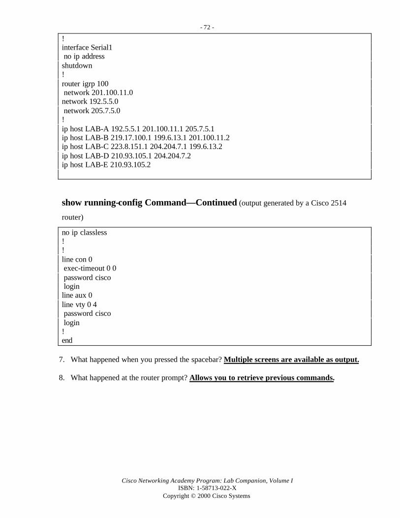
- 72 -
Cisco Networking Academy Program: Lab Companion, Volume IISBN: 1-58713-022-X
Copyright © 2000 Cisco Systems
!interface Serial1 no ip addressshutdown!router igrp 100 network 201.100.11.0network 192.5.5.0 network 205.7.5.0!ip host LAB-A 192.5.5.1 201.100.11.1 205.7.5.1ip host LAB-B 219.17.100.1 199.6.13.1 201.100.11.2ip host LAB-C 223.8.151.1 204.204.7.1 199.6.13.2ip host LAB-D 210.93.105.1 204.204.7.2ip host LAB-E 210.93.105.2
show running-config Command—Continued (output generated by a Cisco 2514
router)
no ip classless!!line con 0 exec-timeout 0 0 password cisco loginline aux 0line vty 0 4 password cisco login!end
7. What happened when you pressed the spacebar? Multiple screens are available as output.
8. What happened at the router prompt? Allows you to retrieve previous commands.
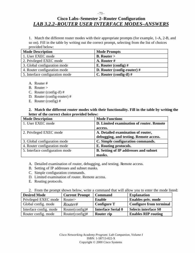
- 73 -
Cisco Networking Academy Program: Lab Companion, Volume IISBN: 1-58713-022-X
Copyright © 2000 Cisco Systems
Cisco Labs–Semester 2–Router ConfigurationLAB 3.2.2–ROUTER USER INTERFACE MODES–ANSWERS
1. Match the different router modes with their appropriate prompts (for example, 1-A, 2-B, andso on). Fill in the table by writing out the correct prompt, selecting from the list of choicesprovided below:
Mode Description Mode Prompts1. User EXEC mode B. Router >2. Privileged EXEC mode A. Router #3. Global configuration mode E. Router (config) #4. Router configuration mode D. Router (config-router) #5. Interface configuration mode C. Router (config-if) #
A. Router #B. Router >C. Router (config-if) #D. Router (config-router) #E. Router (config) #
2. Match the different router modes with their functionality. Fill in the table by writing theletter of the correct choice provided below:
Mode Description Mode Functions1. User EXEC mode D. Limited examination of router. Remote
access.2. Privileged EXEC mode A. Detailed examination of router,
debugging, and testing. Remote access.3. Global configuration mode C. Simple configuration commands.4. Router configuration mode E. Routing protocols.5. Interface configuration mode B. Setting of IP addresses and subnet
masks.
A. Detailed examination of router, debugging, and testing. Remote access.B. Setting of IP addresses and subnet masks.C. Simple configuration commands.D. Limited examination of router. Remote access.E. Routing protocols.
2. From the prompt shown below, write a command that will allow you to enter the mode listed:Desired Mode Current Prompt Command ExplanationPrivileged EXEC mode Router> Enable Enables priv. modeGlobal config. mode Router# Configure T Configure from terminalInterface config. mode Router(config)# Interface Serial 0 Selects interface S0Router config. mode Router(config)# Router rip Enables RIP routing

- 74 -
Cisco Networking Academy Program: Lab Companion, Volume IISBN: 1-58713-022-X
Copyright © 2000 Cisco Systems
Router modes diagram4. In the space provided here or in your Engineering Journal, draw a hierarchical diagram of the
various router modes listed in the background section of the lab. At the top of the hierarchyyou should have the initial router mode that comes up when you boot up the device. Thebottom should have more specific modes. If two or more modes have equal priority, chooseany order.
Reflection:In your journal, describe what general functions the following modes serve:1. Config interface: Allows you to work with and configure a specific interface on a router.2. Enable mode: Provides access to all available router commands and modes.
Also answer the following:1. What did you learn from this lab? __________________________________________________2. Where/when did you have difficulties? ______________________________________________3. How did you overcome them? _____________________________________________________4. How can you apply what you learned in this lab toward future labs? _______________________
User EXECMode
Privileged
EXEC Mode
Router Config
Mode
Global Config
Mode
Interface
Config Mode
Sub-Interface
Mode
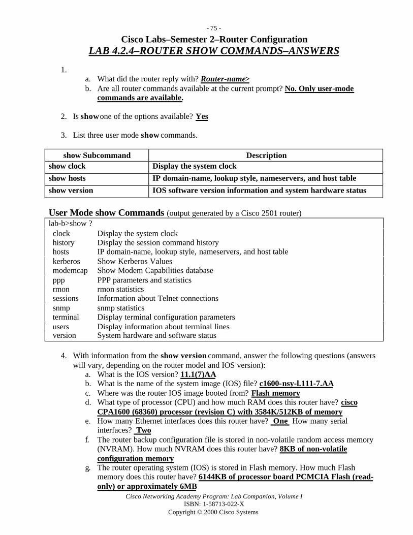
- 75 -
Cisco Networking Academy Program: Lab Companion, Volume IISBN: 1-58713-022-X
Copyright © 2000 Cisco Systems
Cisco Labs–Semester 2–Router ConfigurationLAB 4.2.4–ROUTER SHOW COMMANDS–ANSWERS
1. a. What did the router reply with? Router-name>b. Are all router commands available at the current prompt? No. Only user-mode
commands are available.
2. Is show one of the options available? Yes
3. List three user mode show commands.
show Subcommand Descriptionshow clock Display the system clock
show hosts IP domain-name, lookup style, nameservers, and host table
show version IOS software version information and system hardware status
User Mode show Commands (output generated by a Cisco 2501 router)lab-b>show ? clock Display the system clock history Display the session command history hosts IP domain-name, lookup style, nameservers, and host table kerberos Show Kerberos Values modemcap Show Modem Capabilities database ppp PPP parameters and statistics rmon rmon statistics sessions Information about Telnet connections snmp snmp statistics terminal Display terminal configuration parameters users Display information about terminal lines version System hardware and software status
4. With information from the show version command, answer the following questions (answerswill vary, depending on the router model and IOS version):
a. What is the IOS version? 11.1(7)AAb. What is the name of the system image (IOS) file? c1600-nsy-l.111-7.AAc. Where was the router IOS image booted from? Flash memoryd. What type of processor (CPU) and how much RAM does this router have? cisco
CPA1600 (68360) processor (revision C) with 3584K/512KB of memorye. How many Ethernet interfaces does this router have? One How many serial
interfaces? Twof. The router backup configuration file is stored in non-volatile random access memory
(NVRAM). How much NVRAM does this router have? 8KB of non-volatileconfiguration memory
g. The router operating system (IOS) is stored in Flash memory. How much Flashmemory does this router have? 6144KB of processor board PCMCIA Flash (read-only) or approximately 6MB
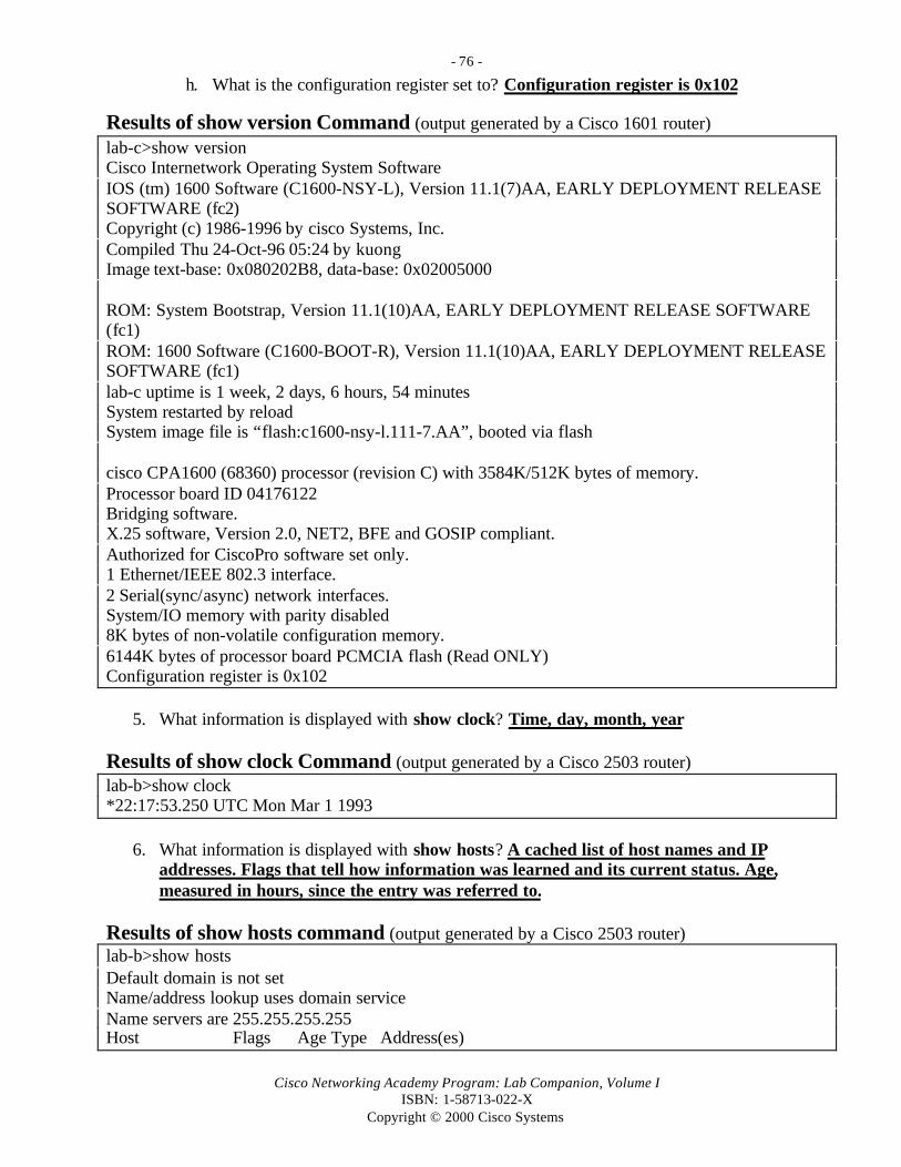
- 76 -
Cisco Networking Academy Program: Lab Companion, Volume IISBN: 1-58713-022-X
Copyright © 2000 Cisco Systems
h. What is the configuration register set to? Configuration register is 0x102
Results of show version Command (output generated by a Cisco 1601 router)lab-c>show versionCisco Internetwork Operating System SoftwareIOS (tm) 1600 Software (C1600-NSY-L), Version 11.1(7)AA, EARLY DEPLOYMENT RELEASESOFTWARE (fc2)Copyright (c) 1986-1996 by cisco Systems, Inc.Compiled Thu 24-Oct-96 05:24 by kuongImage text-base: 0x080202B8, data-base: 0x02005000
ROM: System Bootstrap, Version 11.1(10)AA, EARLY DEPLOYMENT RELEASE SOFTWARE(fc1)ROM: 1600 Software (C1600-BOOT-R), Version 11.1(10)AA, EARLY DEPLOYMENT RELEASESOFTWARE (fc1)lab-c uptime is 1 week, 2 days, 6 hours, 54 minutesSystem restarted by reloadSystem image file is “flash:c1600-nsy-l.111-7.AA”, booted via flash
cisco CPA1600 (68360) processor (revision C) with 3584K/512K bytes of memory.Processor board ID 04176122Bridging software.X.25 software, Version 2.0, NET2, BFE and GOSIP compliant.Authorized for CiscoPro software set only.1 Ethernet/IEEE 802.3 interface.2 Serial(sync/async) network interfaces.System/IO memory with parity disabled8K bytes of non-volatile configuration memory.6144K bytes of processor board PCMCIA flash (Read ONLY)Configuration register is 0x102
5. What information is displayed with show clock? Time, day, month, year
Results of show clock Command (output generated by a Cisco 2503 router)lab-b>show clock*22:17:53.250 UTC Mon Mar 1 1993
6. What information is displayed with show hosts? A cached list of host names and IPaddresses. Flags that tell how information was learned and its current status. Age,measured in hours, since the entry was referred to.
Results of show hosts command (output generated by a Cisco 2503 router)lab-b>show hostsDefault domain is not setName/address lookup uses domain serviceName servers are 255.255.255.255Host Flags Age Type Address(es)

- 77 -
Cisco Networking Academy Program: Lab Companion, Volume IISBN: 1-58713-022-X
Copyright © 2000 Cisco Systems
Results of show hosts Command—Continued (output generated by a Cisco 2514 router)
LAB-A (perm, OK) 22 IP 192.5.5.1 201.100.11.1LAB-B (perm, OK) 22 IP 219.17.100.1 205.7.5.1 199.6.13.1 201.100.11.2LAB-C (perm, OK) 22 IP 223.8.151.1 204.204.7.1 199.6.13.2LAB-D (perm, OK) 22 IP 210.93.105.1 204.204.7.2LAB-E (perm, OK) 22 IP 210.93.105.2
7. What information is displayed with show users? Shows all users connected to the routereither directly or remotely.
Results of show users Command (output generated by a Cisco 2514 router)lab-b>show users Line User Host(s) Idle Location
* 1 aux 0 idle 0
8. What information is displayed with show history? Shows up to the last 10 commandsissued to the router.
Results of show history Command (output generated by a Cisco 2501 router)lab-b>show history show clock show users show history
9. a. What command did you use to enter privileged mode? Enableb. How do you know if you are in privileged mode? The router prompt has a # instead of
> after the router name.
10. a. What did the router reply with? The router responds with the show subcommands
available for privileged mode.b. How is this list different from the list you retrieved in Step 3, when you were in user
mode? Because you are in privileged mode, you have all show subcommandsavailable to you.
11. What is the arp table? The arp table holds IP to MAC to interface mappings.
12. Enter show flash at the router prompt.a. How much Flash memory is available and used? 1506796 available, 6881812 bytes used
b. What is the file that is stored in Flash memory? The IOS file igs-j-l.111-5 is stored inFlash memory.
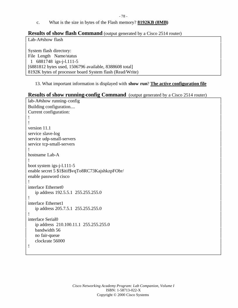
- 78 -
Cisco Networking Academy Program: Lab Companion, Volume IISBN: 1-58713-022-X
Copyright © 2000 Cisco Systems
c. What is the size in bytes of the Flash memory? 8192KB (8MB)
Results of show flash Command (output generated by a Cisco 2514 router)Lab-A#show flash
System flash directory:File Length Name/status 1 6881748 igs-j-l.111-5[6881812 bytes used, 1506796 available, 8388608 total]8192K bytes of processor board System flash (Read/Write)
13. What important information is displayed with show run? The active configuration file
Results of show running-config Command (output generated by a Cisco 2514 router)lab-A#show running-configBuilding configuration....Current configuration:!!version 11.1service slave-logservice udp-small-serversservice tcp-small-servers!hostname Lab-A!boot system igs-j-l.111-5enable secret 5 $1$itif$vqTo8RC73KajshkzpFObr/enable password cisco!interface Ethernet0
ip address 192.5.5.1 255.255.255.0!interface Ethernet1
ip address 205.7.5.1 255.255.255.0!interface Serial0
ip address 210.100.11.1 255.255.255.0bandwidth 56no fair-queueclockrate 56000
!

- 79 -
Cisco Networking Academy Program: Lab Companion, Volume IISBN: 1-58713-022-X
Copyright © 2000 Cisco Systems
Results of show running-config Command—Continued (output generated by a Cisco2514 router)
interface Serial1no ip addressshut down!
router igrp 100network 192.5.5.0network 205.7.5.0network 201.100.11.0!ip host Lab-A 192.5.5.1 205.7.5.1 201.100.11.1ip host Lab-B 219.17.100.1 199.6.13.1 201.100.11.2ip host Lab-C 223.8.151.1 204.204.7.1 199.6.13.2ip host Lab-D 210.93.105.1 204.204.7.2ip host Lab-E 210.93.105.2no ip classless!line con 0exec-timeout 0 0password ciscologinline aux 0line vty 0 4
password ciscologin
end
14. What important information is displayed with show start, and where is this information kept?The backup configuration file, startup-config, is stored in NVRAM.
Results of show startup-config Command (output generated by a Cisco 2514 router)Lab-A#show startup-configUsing 960 out of 32762 bytes!version 11.1service slave-logservice udp-small-serversservice tcp-small-servers!hostname Lab-A!NOTE: The remainder of output should be the same as the show running-config commandunless changes have been made to the current running configuration that have not been copiedto the startup configuration.

- 80 -
Cisco Networking Academy Program: Lab Companion, Volume IISBN: 1-58713-022-X
Copyright © 2000 Cisco Systems
15a. Find the following information for interface Ethernet 0 with Show Interface:1. What is the MTU? Maximum Transmission Unit–Ethernet is 1500 bytes2. What is rely? Reliability of the interface–255/255 is 100% reliable3. What is load? Load on the interface–255/255 is completely saturated4. What is a runt? An Ethernet packet that is less than the 64-byte minimum5. What is a giant? An Ethernet packet that is greater than the 1500-byte maximum
15b. Find the following information for interface serial0 with show interface:1. What is the IP address and subnet mask? 199.6.13.1 255.255.255.02. What data link layer encapsulation is being used? HDLC (High-Level Data Link
Control)3. What does “Serial0 is up, line protocol is up” mean? “Serial0 is up” means that there is
a carrier detect signal. “Line protocol is up” means that keepalive messages arebeing received.
Results of show interface Command (output generated by a Cisco 2514 router)Lab-A#show interfaceEthernet0 is up, line protocol is up Hardware is Lance, address is 0000.0c3b.f3a6 (bia 0000.0c3b.f3a6) Internet address is 192.5.5.1/24 MTU 1500 bytes, BW 10000 Kbit, DLY 1000 usec, rely 255/255, load 1/255 Encapsulation ARPA, loopback not set, keepalive set (10 sec) ARP type: ARPA, ARP Timeout 04:00:00 Last input 00:00:13, output 00:00:02, output hang never Last clearing of “show interface” counters never Queueing strategy: fifo Output queue 0/40, 0 drops; input queue 0/75, 0 drops 5 minute input rate 0 bits/sec, 0 packets/sec 5 minute output rate 0 bits/sec, 0 packets/sec 27107 packets input, 15017900 bytes, 0 no buffer Received 172 broadcasts, 0 runts, 0 giants 3 input errors, 3 CRC, 0 frame, 0 overrun, 0 ignored, 0 abort 0 input packets with dribble condition detected 37514 packets output, 2657602 bytes, 0 underruns 0 output errors, 0 collisions, 1 interface resets 0 babbles, 0 late collision, 0 deferred 0 lost carrier, 0 no carrier 0 output buffer failures, 0 output buffers swapped out 10553 packets output, 1038298 bytes, 0 underruns 0 output errors, 0 collisions, 1 interface resets 0 babbles, 0 late collision, 0 deferred 0 lost carrier, 0 no carrier 0 output buffer failures, 0 output buffers swapped out

- 81 -
Cisco Networking Academy Program: Lab Companion, Volume IISBN: 1-58713-022-X
Copyright © 2000 Cisco Systems
Results of show interface Command—Continued (output generated by a Cisco 2514router)Serial0 is up, line protocol is up Hardware is HD64570 Internet address is 210.100.11.1/24 MTU 1500 bytes, BW 56 Kbit, DLY 20000 usec, rely 255/255, load 1/255 Encapsulation HDLC, loopback not set, keepalive set (10 sec) Last input 00:00:00, output 00:00:07, output hang never Last clearing of “show interface” counters never Queueing strategy: fifo Output queue 0/40, 0 drops; input queue 0/75, 0 drops 5 minute input rate 0 bits/sec, 0 packets/sec 5 minute output rate 0 bits/sec, 0 packets/sec 10513 packets input, 667585 bytes, 0 no buffer Received 10488 broadcasts, 0 runts, 0 giants 0 input errors, 0 CRC, 0 frame, 0 overrun, 0 ignored, 0 abort 10411 packets output, 643047 bytes, 0 underruns 0 output errors, 0 collisions, 2 interface resets 0 output buffer failures, 0 output buffers swapped out 0 carrier transitions DCD=up DSR=up DTR=up RTS=up CTS=up
Remainder of output truncated.
16. What important information is displayed? Global and interface-specific status of anyconfigured level 3 protocols
Results of show protocol Command (output generated by a Cisco 2514 router)Lab-A#show protocolGlobal values: Internet Protocol routing is enabled
Ethernet0 is up, line protocol is up Internet address is 192.5.5.1/24
Ethernet1 is up, line protocol is up Internet address is 205.7.5.1/24
Serial0 is up, line protocol is up Internet address is 199.6.13.1/24
Serial1 is administratively down, line protocol is down
17. Enter exit at the router prompt.

- 82 -
Cisco Networking Academy Program: Lab Companion, Volume IISBN: 1-58713-022-X
Copyright © 2000 Cisco Systems
Cisco Labs–Semester 2–Router ConfigurationLAB 4.3.5–CDP NEIGHBORS–ANSWERS
1. Connect to the router and log in. Enter the password cisco if prompted. Gather informationabout the router you logged in to by issuing the show interface command. Document thefollowing information about the router:
a. What is the name of the router? Lab-c
b. List IP address and subnet mask of the interfaces.
Interface IP Address Subnet MaskEthernet 0 223.8.151.1 24 bits (255.255.255.0)Serial 0 204.204.7.1 24 bits (255.255.255.0)
Serial 1 199.6.13.2 24 bits (255.255.255.0)
c. List operational status of each interface.
Interface Interface Up or Down?(Carrier Detect Signal)
Line Protocol Up or Down?(Keepalives Being Received)
Ethernet 0 Up Up
Serial 0 Up UpSerial 1 Up Up
Results of show interface Command (output generated by a Cisco 1601 router)lab-c>show interfaceEthernet0 is up, line protocol is up Hardware is QUICC Ethernet, address is 0060.474f.9bbd (bia 0060.474f.9bbd) Internet address is 223.8.151.1/24 MTU 1500 bytes, BW 10000 Kbit, DLY 1000 usec, rely 255/255, load 1/255 Encapsulation ARPA, loopback not set, keepalive set (10 sec) ARP type: ARPA, ARP Timeout 04:00:00 Last input 2d02h, output 00:00:02, output hang never Last clearing of “show interface” counters never Queueing strategy: fifo Output queue 0/40, 0 drops; input queue 0/75, 0 drops 5 minute input rate 0 bits/sec, 0 packets/sec 5 minute output rate 0 bits/sec, 0 packets/sec 7 packets input, 570 bytes, 0 no buffer Received 7 broadcasts, 0 runts, 0 giants0 input errors, 0 CRC, 0 frame, 0 overrun, 0 ignored, 0 abort 0 input packets with dribble condition detected 100196 packets output, 10049637 bytes, 0 underruns 0 output errors, 0 collisions, 1 interface resets

- 83 -
Cisco Networking Academy Program: Lab Companion, Volume IISBN: 1-58713-022-X
Copyright © 2000 Cisco Systems
Results of show interface Command–Continued (output generated by a Cisco 1601 router) 0 babbles, 0 late collision, 0 deferred 0 lost carrier, 0 no carrier 0 output buffer failures, 0 output buffers swapped outSerial0 is up, line protocol is up Hardware is QUICC Serial Internet address is 204.204.7.1/24 MTU 1500 bytes, BW 56 Kbit, DLY 20000 usec, rely 255/255, load 1/255 Encapsulation HDLC, loopback not set, keepalive set (10 sec) Last input 00:00:08, output 00:00:04, output hang never Last clearing of “show interface” counters never Input queue: 0/75/0 (size/max/drops); Total output drops: 0 Queueing strategy: weighted fair Output queue: 0/64/0 (size/threshold/drops) Conversations 0/1 (active/max active)Reserved Conversations 0/0 (allocated/max allocated)5 minute input rate 0 bits/sec, 0 packets/sec 5 minute output rate 0 bits/sec, 0 packets/sec 129492 packets input, 8117948 bytes, 0 no buffer Received 126687 broadcasts, 0 runts, 0 giants 0 input errors, 0 CRC, 0 frame, 0 overrun, 0 ignored, 0 abort 103169 packets output, 6985930 bytes, 0 underruns 0 output errors, 0 collisions, 7 interface resets 0 output buffer failures, 0 output buffers swapped out 18 carrier transitions DCD=up DSR=up DTR=up RTS=up CTS=up
Serial1 is up, line protocol is up Hardware is QUICC Serial Internet address is 199.6.13.2/24 MTU 1500 bytes, BW 56 Kbit, DLY 20000 usec, rely 255/255, load 4/255 Encapsulation HDLC, loopback not set, keepalive set (10 sec) Last input 00:00:00, output 00:00:02, output hang never Last clearing of “show interface” counters never Input queue: 0/75/0 (size/max/drops); Total output drops: 0 Queueing strategy: weighted fair Output queue: 0/64/0 (size/threshold/drops) Conversations 0/3 (active/max active) Reserved Conversations 0/0 (allocated/max allocated) 5 minute input rate 1000 bits/sec, 2 packets/sec 5 minute output rate 1000 bits/sec, 2 packets/sec107132 packets input, 5830048 bytes, 0 no buffer Received 102593 broadcasts, 0 runts, 0 giants 1 input errors, 0 CRC, 1 frame, 0 overrun, 0 ignored, 0 abort 104562 packets output, 6840784 bytes, 0 underruns 0 output errors, 0 collisions, 6 interface resets

- 84 -
Cisco Networking Academy Program: Lab Companion, Volume IISBN: 1-58713-022-X
Copyright © 2000 Cisco Systems
Results of show interface Command–Continued (output generated by a Cisco 1601 router) 0 output buffer failures, 0 output buffers swapped out 290 carrier transitions DCD=up DSR=up DTR=up RTS=up CTS=up
2. How often is the router sending CDP packets? Every 60 seconds
3. What is the hold time value? 180 seconds
Results of show cdp Command (output generated by a Cisco 2514 router)lab-b>show cdpGlobal CDP information:
Sending CDP packets every 60 secondsSending a holdtime value of 180 seconds
4. Fill in the following table. (Answers may vary depending on lab setup. In this case, Lab-B is a2514, and there is a Catalyst 1900 switch attached to the same Ethernet hub that Lab-B isattached to. Lab-A and Lab-C are Cisco 1600 models.)
Device and PortID Local Interface Hold Time Capability Platform
Lab-c, Serial1 Serial0 166 Router CPA1600
Lab-a, Serial0 Serial1 151 Router CPA160000C01D 81259B,Port 1
Ethernet1 136 Trans BridgeSwitch
1900
Results of show cdp neighbors Command (output generated by a Cisco 2514 router)lab-b>show cdp neighborsCapability Codes: R - Router, T - Trans Bridge, B - Source Route Bridge
S - Switch, H - Host, I - IGMP
Device ID Local Intrfce Holdtme Capability Platform Port IDlab-c Ser 0 166 R CPA1600 Ser 1lab-a Ser 1 151 R 2500 Ser 000C01D 81259B Eth 1 136 T S 1900 1(Note: The last entry is the MAC address of a Cisco Catalyst 1900 Ethernet switch.)

- 85 -
Cisco Networking Academy Program: Lab Companion, Volume IISBN: 1-58713-022-X
Copyright © 2000 Cisco Systems
5. Fill in the following table:Neighbor device name Lab-c Lab-a 00C01D81259B
Neighbor device type Cisco CPA1600 Cisco CPA1600 Cisco 1900 switch
IP address of interfaceattached to your router
199.6.13.2 201.100.11.1 205.7.5.2
Port ID of your router thatthe neighbor is on Serial0 Serial1 Ethernet1
Port ID of neighbor routerthat your router is on
Serial1 Serial0 Port1
IOS version of neighborrouter 11.1(7)AA 11.1(7)AA V5.35
Results of show cdp neighbors detail Command (output generated by a Cisco 2514 router)
lab-b>show cdp neighbors detailDevice ID: lab-cEntry address(es): IP address: 199.6.13.2Platform: cisco CPA1600, Capabilities: RouterInterface: Serial0, Port ID (outgoing port): Serial1Holdtime : 142 sec
Version :Cisco Internetwork Operating System SoftwareIOS (tm) 1600 Software (C1600-NSY-L), Version 11.1(7)AA, EARLY DEPLOYMENT RELEASESOFTWARE (fc2)Copyright (c) 1986-1996 by cisco Systems, Inc.Compiled Thu 24-Oct-96 05:24 by kuong
Device ID: lab-aEntry address(es): IP address: 201.100.11.1Platform: cisco CPA1600, Capabilities: RouterInterface: Serial1, Port ID (outgoing port): Serial0Holdtime : 173 sec
Version :Cisco Internetwork Operating System SoftwareIOS (tm) 1600 Software (C1600-NSY-L), Version 11.1(7)AA, EARLY DEPLOYMENT RELEASESOFTWARE (fc2)Copyright (c) 1986-1996 by cisco Systems, Inc.Compiled Thu 24-Oct-96 05:24 by kuongDevice ID: 00C01D 81259BEntry address(es):
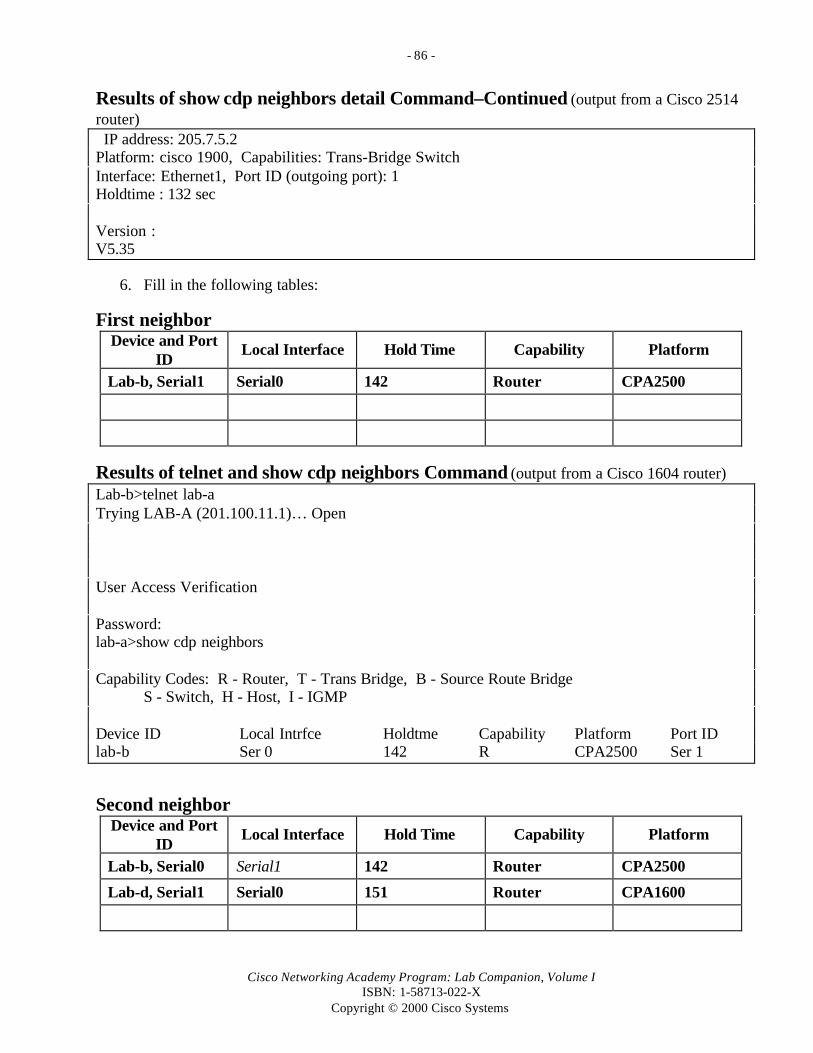
- 86 -
Cisco Networking Academy Program: Lab Companion, Volume IISBN: 1-58713-022-X
Copyright © 2000 Cisco Systems
Results of show cdp neighbors detail Command–Continued (output from a Cisco 2514router) IP address: 205.7.5.2Platform: cisco 1900, Capabilities: Trans-Bridge SwitchInterface: Ethernet1, Port ID (outgoing port): 1Holdtime : 132 sec
Version :V5.35
6. Fill in the following tables:
First neighborDevice and Port
IDLocal Interface Hold Time Capability Platform
Lab-b, Serial1 Serial0 142 Router CPA2500
Results of telnet and show cdp neighbors Command (output from a Cisco 1604 router)Lab-b>telnet lab-aTrying LAB-A (201.100.11.1)… Open
User Access Verification
Password:lab-a>show cdp neighbors
Capability Codes: R - Router, T - Trans Bridge, B - Source Route BridgeS - Switch, H - Host, I - IGMP
Device ID Local Intrfce Holdtme Capability Platform Port IDlab-b Ser 0 142 R CPA2500 Ser 1
Second neighborDevice and Port
IDLocal Interface Hold Time Capability Platform
Lab-b, Serial0 Serial1 142 Router CPA2500
Lab-d, Serial1 Serial0 151 Router CPA1600

- 87 -
Cisco Networking Academy Program: Lab Companion, Volume IISBN: 1-58713-022-X
Copyright © 2000 Cisco Systems
Results of telnet and show cdp neighbors Command (output from a Cisco 1601 router)
Lab-b>telnet lab-cTrying LAB-C (199.6.13.2)… Open
User Access Verification
Password:
lab-c>show cdp neighborsCapability Codes: R - Router, T - Trans Bridge, B - Source Route Bridge
S - Switch, H - Host, I - IGMP
Device ID Local Intrfce Holdtme Capability Platform Port IDlab-b Ser 1 142 R CPA2500 Ser 0lab-d Ser 0 151 R CPA1600 Ser 1

- 88 -
Cisco Networking Academy Program: Lab Companion, Volume IISBN: 1-58713-022-X
Copyright © 2000 Cisco Systems
Cisco Labs–Semester 2–Router ConfigurationLAB 4.4.2–REMOTE TELNET ACCESS–ANSWERS
1. Connect to the router and log in. Enter the password cisco if prompted. What prompt didthe router display? Router-Name> (of local router)
2. Enter telnet ? at the router prompt. What did the router reply with? WORD IP address orhostname of a remote system
3. Enter telnet router-name or IP address at the router prompt. The router will prompt youfor user access verification of the router you remotely access. Enter the password cisco.What prompt did the router display? Router-Name> (of remote router)
4. Enter show interface at the prompt of the remote router. List the interfaces, their IPaddress, and subnet mask from the remote router. (The following is for router Lab-C.)
Interface IP Address Subnet MaskEthernet 0 223.8.151.1 24 bits (255.255.255.0)
Serial 0 204.204.7.1 24 bits (255.255.255.0)Serial 1 199.6.13.2 24 bits (255.255.255.0)
Results of telnet and show interface Command (output generated by a Cisco 1600Router)lab-b>telnet lab-dTrying LAB-D (210.93.105.1)... Open
User Access Verification
Password:lab-D>show interface
Ethernet0 is up, line protocol is up Hardware is QUICC Ethernet, address is 0060.5cbc.033a (bia 0060.5cbc.033a) Internet address is 210.93.105.1/24 MTU 1500 bytes, BW 10000 Kbit, DLY 1000 usec, rely 255/255, load 1/255 Encapsulation ARPA, loopback not set, keepalive set (10 sec) ARP type: ARPA, ARP Timeout 04:00:00 Last input 00:00:28, output 00:00:04, output hang never Last clearing of “show interface” counters never Queueing strategy: fifo Output queue 0/40, 0 drops; input queue 0/75, 0 drops 5 minute input rate 0 bits/sec, 0 packets/sec 5 minute output rate 0 bits/sec, 0 packets/sec 13661 packets input, 4186769 bytes, 0 no buffer Received 12931 broadcasts, 0 runts, 0 giants

- 89 -
Cisco Networking Academy Program: Lab Companion, Volume IISBN: 1-58713-022-X
Copyright © 2000 Cisco Systems
0 input errors, 0 CRC, 0 frame, 0 overrun, 0 ignored, 0 abort
Results of telnet and show interface Command–Continued (output generated bya Cisco 1600 router) 0 input packets with dribble condition detected 113212 packets output, 10955040 bytes, 0 underruns 0 output errors, 0 collisions, 1 interface resets 0 babbles, 0 late collision, 4 deferred 0 lost carrier, 0 no carrier 0 output buffer failures, 0 output buffers swapped outSerial0 is administratively down, line protocol is down Hardware is QUICC Serial MTU 1500 bytes, BW 1544 Kbit, DLY 20000 usec, rely 255/255, load 1/255 Encapsulation HDLC, loopback not set, keepalive set (10 sec) Last input never, output never, output hang never Last clearing of “show interface” counters never Input queue: 0/75/0 (size/max/drops); Total output drops: 0 Queueing strategy: weighted fair Output queue: 0/64/0 (size/threshold/drops) Conversations 0/0 (active/max active) Reserved Conversations 0/0 (allocated/max allocated) 5 minute input rate 0 bits/sec, 0 packets/sec 5 minute output rate 0 bits/sec, 0 packets/sec 0 packets input, 0 bytes, 0 no buffer Received 0 broadcasts, 0 runts, 0 giants 0 input errors, 0 CRC, 0 frame, 0 overrun, 0 ignored, 0 abort 0 packets output, 0 bytes, 0 underruns 0 output errors, 0 collisions, 6 interface resets 0 output buffer failures, 0 output buffers swapped out 0 carrier transitions DCD=down DSR=down DTR=down RTS=down CTS=down
Serial1 is up, line protocol is up Hardware is QUICC Serial Internet address is 204.204.7.2/24 MTU 1500 bytes, BW 1544 Kbit, DLY 20000 usec, rely 255/255, load 1/255 Encapsulation HDLC, loopback not set, keepalive set (10 sec) Last input 00:00:00, output 00:00:01, output hang never Last clearing of “show interface” counters never Input queue: 0/75/0 (size/max/drops); Total output drops: 0 Queueing strategy: weighted fair Output queue: 0/64/0 (size/threshold/drops) Conversations 0/2 (active/max active) Reserved Conversations 0/0 (allocated/max allocated) 5 minute input rate 1000 bits/sec, 2 packets/sec 5 minute output rate 1000 bits/sec, 2 packets/sec 88358 packets input, 6001075 bytes, 0 no buffer Received 86058 broadcasts, 0 runts, 0 giants

- 90 -
Cisco Networking Academy Program: Lab Companion, Volume IISBN: 1-58713-022-X
Copyright © 2000 Cisco Systems
Note: Output truncated.
5. Enter show protocols at the router prompt. Fill in the table below with the informationthat was generated by the router you are remotely accessing.
Interface Is there a carrier detectsignal?
Are the keepalive messagesbeing received?
Ethernet 0 Yes Yes
Serial 0 No (administratively down) No
Serial 1 Yes Yes
Output Generated by a Cisco 1600 Routerlab-D>show protocolsGlobal values:Internet Protocol routing is enabledEthernet0 is up, line protocol is up Internet address is 210.93.105.1/24Serial0 is administratively down, line protocol is downSerial1 is up, line protocol is up Internet address is 204.204.7.2/24
6. Enter enable at the remote router prompt while connected to it with telnet. The router willprompt you for a password. Enter class. What prompt did the router display? Router-Name# What mode are you in? Privileged EXEC mode
7. Enter show running-config at the router prompt. What file are you viewing on the remoterouter? The active configuration file Is this file stored in NVRAM? No. The backupconfiguration file is stored in NVRAM.
8. Enter show startup-config at the router prompt. What file are you viewing on the remoterouter? The backup configuration file
9. What information do you see concerning the line VTY connections?line vty 0 4 (refers to the five possible telnet sessions the router can support)password cisco (defines the required password for any incoming telnet sessions)login (prompts the user for the password when he attempts to connect)
10. Enter show cdp neighbors at the router prompt. List all device IDs that are connected tothe remote router you have a telnet session with.
lab-D>show cdp neighborsCapability Codes: R - Router, T - Trans Bridge, B - Source Route Bridge
S - Switch, H - Host, I - IGMP, r - Repeater
Device ID Local Intrfce Holdtme Capability Platform Port IDLab-C Ser 1 165 R CPA1600 Ser 0Lab-E Eth 0 176 R CPA1600 Eth

- 91 -
Cisco Networking Academy Program: Lab Companion, Volume IISBN: 1-58713-022-X
Copyright © 2000 Cisco Systems
Cisco Labs–Semester 2–Router ConfigurationLAB 4.4.3–ICMP PING–ANSWERS
1.a. What prompt did the router display? Router Name>
b. What does it mean? You are at a user-mode prompt that allows you to displaysome information without changing router configuration settings.
2. List four host names and the first IP address listed.
Host Name IP Address
Lab-a 192.5.5.1
Lab-c 223.8.151.1
Lab-d 210.93.105.1
Lab-e 210.93.105.2
lab-b>show hostDefault domain is not setName/address lookup uses domain serviceName servers are 255.255.255.255
Host Flags Age Type Address(es)LAB-A (perm, OK) 22 IP 192.5.5.1 205.7.5.1 201.100.11.1LAB-B (perm, OK) 22 IP 219.17.100.1 199.6.13.1 201.100.11.2LAB-C (perm, OK) 22 IP 223.8.151.1 204.204.7.1 199.6.13.2LAB-D (perm, OK) 22 IP 210.93.105.1 204.204.7.2LAB-E (perm, OK) 22 IP 210.93.105.2
3. Were you able to ping all the IP addresses? Yes
4. List four important pieces of information that you received after issuing the ping command.How many ICMP echoes were sent and how big the packets were; what the timeoutduration is; what the success rate is; and what the minimum, average, and maximumround-trip times are
Output Generated by a Cisco 2501 Routerlab-b#ping 204.204.7.1
Type escape sequence to abort.Sending 5, 100-byte ICMP Echoes to 204.204.7.1, timeout is 2 seconds:!!!!!Success rate is 100 percent (5/5), round-trip min/avg/max = 36/36/36 ms
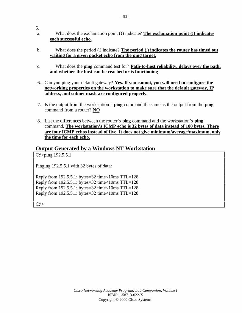
- 92 -
Cisco Networking Academy Program: Lab Companion, Volume IISBN: 1-58713-022-X
Copyright © 2000 Cisco Systems
5.a. What does the exclamation point (!) indicate? The exclamation point (!) indicates
each successful echo.
b. What does the period (.) indicate? The period (.) indicates the router has timed outwaiting for a given packet echo from the ping target.
c. What does the ping command test for? Path-to-host reliability, delays over the path,and whether the host can be reached or is functioning
6. Can you ping your default gateway? Yes. If you cannot, you will need to configure thenetworking properties on the workstation to make sure that the default gateway, IPaddress, and subnet mask are configured properly.
7. Is the output from the workstation’s ping command the same as the output from the pingcommand from a router? NO
8. List the differences between the router’s ping command and the workstation’s pingcommand. The workstation’s ICMP echo is 32 bytes of data instead of 100 bytes. Thereare four ICMP echos instead of five. It does not give minimum/average/maximum, onlythe time for each echo.
Output Generated by a Windows NT WorkstationC:\>ping 192.5.5.1
Pinging 192.5.5.1 with 32 bytes of data:
Reply from 192.5.5.1: bytes=32 time<10ms TTL=128Reply from 192.5.5.1: bytes=32 time<10ms TTL=128Reply from 192.5.5.1: bytes=32 time<10ms TTL=128Reply from 192.5.5.1: bytes=32 time<10ms TTL=128
C:\>
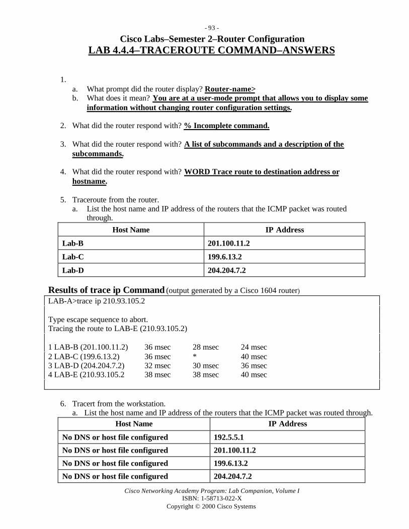
- 93 -
Cisco Networking Academy Program: Lab Companion, Volume IISBN: 1-58713-022-X
Copyright © 2000 Cisco Systems
Cisco Labs–Semester 2–Router ConfigurationLAB 4.4.4–TRACEROUTE COMMAND–ANSWERS
1. a. What prompt did the router display? Router-name>b. What does it mean? You are at a user-mode prompt that allows you to display some
information without changing router configuration settings.
2. What did the router respond with? % Incomplete command.
3. What did the router respond with? A list of subcommands and a description of thesubcommands.
4. What did the router respond with? WORD Trace route to destination address orhostname.
5. Traceroute from the router.a. List the host name and IP address of the routers that the ICMP packet was routed
through.
Host Name IP Address
Lab-B 201.100.11.2
Lab-C 199.6.13.2
Lab-D 204.204.7.2
Results of trace ip Command (output generated by a Cisco 1604 router)
LAB-A>trace ip 210.93.105.2
Type escape sequence to abort.Tracing the route to LAB-E (210.93.105.2)
1 LAB-B (201.100.11.2) 36 msec 28 msec 24 msec2 LAB-C (199.6.13.2) 36 msec * 40 msec3 LAB-D (204.204.7.2) 32 msec 30 msec 36 msec4 LAB-E (210.93.105.2 38 msec 38 msec 40 msec
6. Tracert from the workstation.a. List the host name and IP address of the routers that the ICMP packet was routed through.
Host Name IP Address
No DNS or host file configured 192.5.5.1
No DNS or host file configured 201.100.11.2
No DNS or host file configured 199.6.13.2
No DNS or host file configured 204.204.7.2
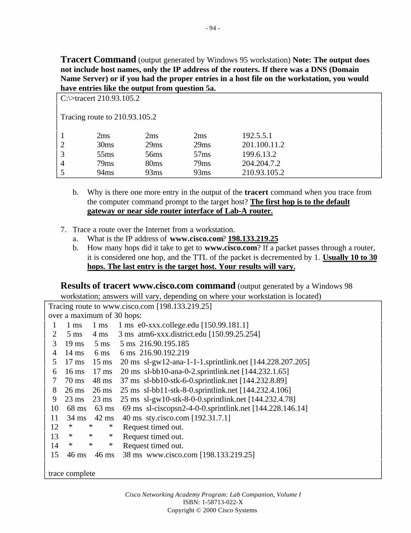
- 94 -
Cisco Networking Academy Program: Lab Companion, Volume IISBN: 1-58713-022-X
Copyright © 2000 Cisco Systems
Tracert Command (output generated by Windows 95 workstation) Note: The output doesnot include host names, only the IP address of the routers. If there was a DNS (DomainName Server) or if you had the proper entries in a host file on the workstation, you wouldhave entries like the output from question 5a.C:\>tracert 210.93.105.2
Tracing route to 210.93.105.2
1 2ms 2ms 2ms 192.5.5.12 30ms 29ms 29ms 201.100.11.23 55ms 56ms 57ms 199.6.13.24 79ms 80ms 79ms 204.204.7.25 94ms 93ms 93ms 210.93.105.2
b. Why is there one more entry in the output of the tracert command when you trace fromthe computer command prompt to the target host? The first hop is to the defaultgateway or near side router interface of Lab-A router.
7. Trace a route over the Internet from a workstation.a. What is the IP address of www.cisco.com? 198.133.219.25b. How many hops did it take to get to www.cisco.com? If a packet passes through a router,
it is considered one hop, and the TTL of the packet is decremented by 1. Usually 10 to 30hops. The last entry is the target host. Your results will vary.
Results of tracert www.cisco.com command (output generated by a Windows 98workstation; answers will vary, depending on where your workstation is located)
Tracing route to www.cisco.com [198.133.219.25]over a maximum of 30 hops: 1 1 ms 1 ms 1 ms e0-xxx.college.edu [150.99.181.1] 2 5 ms 4 ms 3 ms atm6-xxx.district.edu [150.99.25.254] 3 19 ms 5 ms 5 ms 216.90.195.185 4 14 ms 6 ms 6 ms 216.90.192.219 5 17 ms 15 ms 20 ms sl-gw12-ana-1-1-1.sprintlink.net [144.228.207.205] 6 16 ms 17 ms 20 ms sl-bb10-ana-0-2.sprintlink.net [144.232.1.65] 7 70 ms 48 ms 37 ms sl-bb10-stk-6-0.sprintlink.net [144.232.8.89] 8 26 ms 26 ms 25 ms sl-bb11-stk-8-0.sprintlink.net [144.232.4.106] 9 23 ms 23 ms 25 ms sl-gw10-stk-8-0-0.sprintlink.net [144.232.4.78] 10 68 ms 63 ms 69 ms sl-ciscopsn2-4-0-0.sprintlink.net [144.228.146.14] 11 34 ms 42 ms 40 ms sty.cisco.com [192.31.7.1] 12 * * * Request timed out. 13 * * * Request timed out. 14 * * * Request timed out. 15 46 ms 46 ms 38 ms www.cisco.com [198.133.219.25]
trace complete

- 95 -
Cisco Networking Academy Program: Lab Companion, Volume IISBN: 1-58713-022-X
Copyright © 2000 Cisco Systems
8. List the IP networks that are directly connected to you. 201.100.11.0, 199.6.13.0,219.17.100.0
Results of show ip route (output generated by a Cisco 2514 router)LAB-B>show ip routeCodes: C - connected, S - static, I - IGRP, R - RIP, M - mobile, B - BGP D - EIGRP, EX - EIGRP external, O - OSPF, IA - OSPF inter area E1 - OSPF external type 1, E2 - OSPF external type 2, E - EGP i - IS-IS, L1 - IS-IS level-1, L2 - IS-IS level-2, * - candidate default U - per-user static route
Gateway of last resort is not set
C 201.100.11.0/24 is directly connected, Serial1C 199.6.13.0/24 is directly connected, Serial0C 219.17.100.0/24 is directly connected, Ethernet0R 192.5.5.0/24 [120/1] VIA 201.100.11.1 00:00:20 Serial1R 205.7.5.0/24 [120/1] VIA 201.100.11.1 00:00:20 Serial1R 223.8.151.0/24 [120/1] VIA 199.6.13.2 00:00:20 Serial0R 204.204.7.0/24 [120/1] VIA 199.6.13.2 00:00:20 Serial0R 210.93.105.0/24 [120/1] VIA 199.6.13.00:00:20 Serial0

- 96 -
Cisco Networking Academy Program: Lab Companion, Volume IISBN: 1-58713-022-X
Copyright © 2000 Cisco Systems
Cisco Labs–Semester 2–Router ConfigurationLAB 4.4.7–SHOW INTERFACE and CLEAR COUNTERS–
ANSWERS
1. Fill in the following information in the table for all interfaces (answers will vary):
Interface Ethernet 0 Ethernet 1 Serial 0 Serial 1Hardware address 0000.0c3b.f3a6 0000.0c3b.f3a7 HD64570 HD64570
Packet input 27107 1301 10513 10446
Packet output 37514 10553 10411 10392
Last clearing ofcounters
Never Never never Never
Results of show interface Command (output generated by a Cisco 2514 router)lab-b#show interfaceEthernet0 is up, line protocol is up Hardware is Lance, address is 0000.0c3b.f3a6 (bia 0000.0c3b.f3a6) Internet address is 219.17.100.1/24 MTU 1500 bytes, BW 10000 Kbit, DLY 1000 usec, rely 255/255, load 1/255 Encapsulation ARPA, loopback not set, keepalive set (10 sec) ARP type: ARPA, ARP Timeout 04:00:00 Last input 00:00:13, output 00:00:02, output hang never Last clearing of "show interface" counters never Queueing strategy: fifoOutput queue 0/40, 0 drops; input queue 0/75, 0 drops 5 minute input rate 0 bits/sec, 0 packets/sec5 minute output rate 0 bits/sec, 0 packets/sec 27107 packets input, 15017900 bytes, 0 no buffer Received 172 broadcasts, 0 runts, 0 giants 3 input errors, 3 CRC, 0 frame, 0 overrun, 0 ignored, 0 abort 0 input packets with dribble condition detected 37514 packets output, 2657602 bytes, 0 underruns 0 output errors, 0 collisions, 1 interface resets 0 babbles, 0 late collision, 0 deferred 0 lost carrier, 0 no carrier 0 output buffer failures, 0 output buffers swapped outEthernet1 is up, line protocol is up Hardware is Lance, address is 0000.0c3b.f3a7 (bia 0000.0c3b.f3a7) Internet address is 205.7.5.1/24 MTU 1500 bytes, BW 10000 Kbit, DLY 1000 usec, rely 255/255, load 1/255 Encapsulation ARPA, loopback not set, keepalive set (10 sec) ARP type: ARPA, ARP Timeout 04:00:00 Last input 00:00:59, output 00:00:05, output hang never Last clearing of "show interface" counters never Queueing strategy: fifo Output queue 0/40, 0 drops; input queue 0/75, 0 drops

- 97 -
Cisco Networking Academy Program: Lab Companion, Volume IISBN: 1-58713-022-X
Copyright © 2000 Cisco Systems
5 minute input rate 0 bits/sec, 0 packets/secResults of show interface Command–Continued (output generated by a Cisco 2514 router) 5 minute output rate 0 bits/sec, 0 packets/sec 1301 packets input, 126197 bytes, 0 no buffer Received 1301 broadcasts, 0 runts, 0 giants 0 input errors, 0 CRC, 0 frame, 0 overrun, 0 ignored, 0 abort 0 input packets with dribble condition detected 10553 packets output, 1038298 bytes, 0 underruns 0 output errors, 0 collisions, 1 interface resets 0 babbles, 0 late collision, 0 deferred 0 lost carrier, 0 no carrier 0 output buffer failures, 0 output buffers swapped outSerial0 is up, line protocol is up Hardware is HD64570 Internet address is 199.6.13.1/24 MTU 1500 bytes, BW 56 Kbit, DLY 20000 usec, rely 255/255, load 1/255 Encapsulation HDLC, loopback not set, keepalive set (10 sec) Last input 00:00:00, output 00:00:07, output hang never Last clearing of “show interface” counters never Queueing strategy: fifo Output queue 0/40, 0 drops; input queue 0/75, 0 drops 5 minute input rate 0 bits/sec, 0 packets/sec 5 minute output rate 0 bits/sec, 0 packets/sec 10513 packets input, 667585 bytes, 0 no buffer Received 10488 broadcasts, 0 runts, 0 giants 0 input errors, 0 CRC, 0 frame, 0 overrun, 0 ignored, 0 abort 10411 packets output, 643047 bytes, 0 underruns 0 output errors, 0 collisions, 2 interface resets 0 output buffer failures, 0 output buffers swapped out 0 carrier transitions DCD=up DSR=up DTR=up RTS=up CTS=upSerial1 is up, line protocol is up Hardware is HD64570 Internet address is 201.100.11.2/24 MTU 1500 bytes, BW 1544 Kbit, DLY 20000 usec, rely 255/255, load 1/255 Encapsulation HDLC, loopback not set, keepalive set (10 sec) Last input 00:00:00, output 00:00:08, output hang never Last clearing of “show interface” counters never Input queue: 0/75/0 (size/max/drops); Total output drops: 0 Queueing strategy: weighted fair Output queue: 0/64/0 (size/threshold/drops) Conversations 0/1 (active/max active) Reserved Conversations 0/0 (allocated/max allocated) 5 minute input rate 0 bits/sec, 0 packets/sec 5 minute output rate 0 bits/sec, 0 packets/sec 10446 packets input, 633493 bytes, 0 no buffer
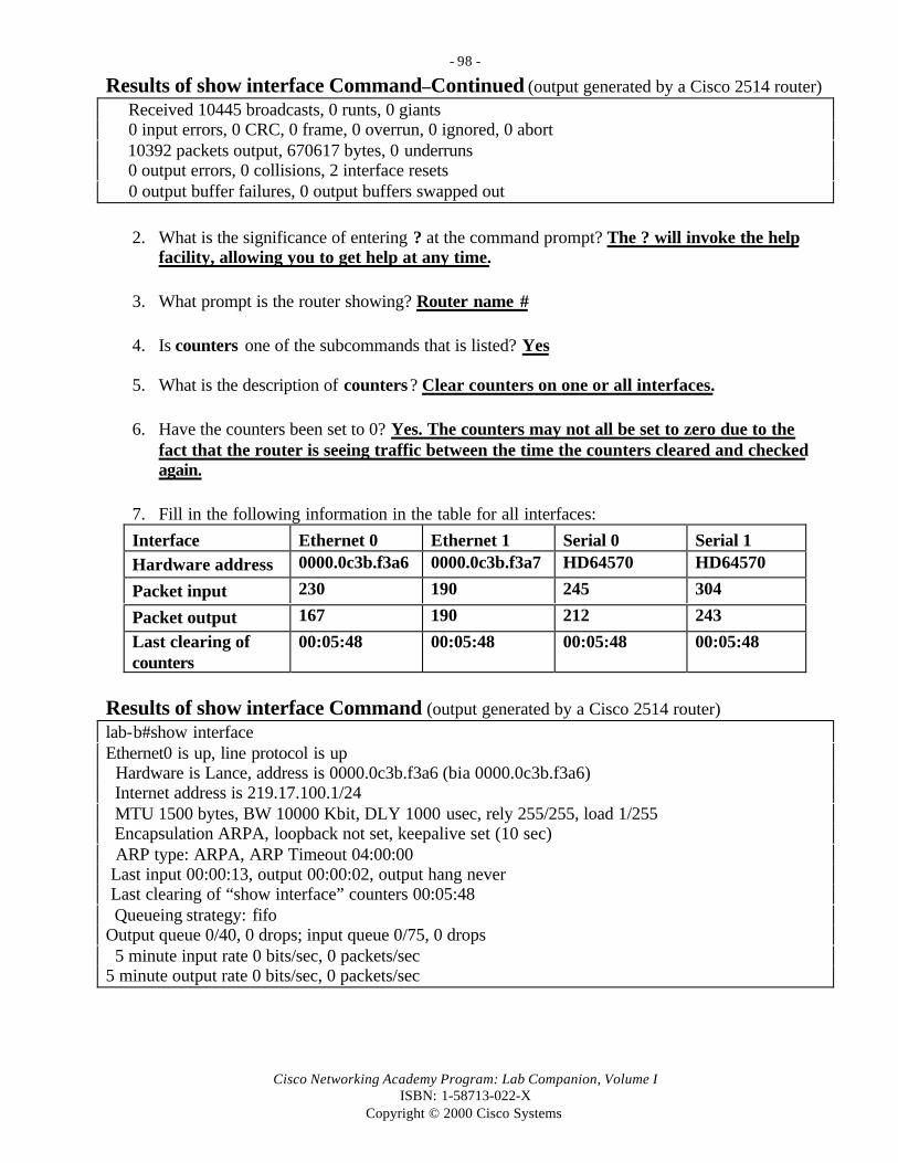
- 98 -
Cisco Networking Academy Program: Lab Companion, Volume IISBN: 1-58713-022-X
Copyright © 2000 Cisco Systems
Results of show interface Command–Continued (output generated by a Cisco 2514 router) Received 10445 broadcasts, 0 runts, 0 giants 0 input errors, 0 CRC, 0 frame, 0 overrun, 0 ignored, 0 abort 10392 packets output, 670617 bytes, 0 underruns 0 output errors, 0 collisions, 2 interface resets 0 output buffer failures, 0 output buffers swapped out
2. What is the significance of entering ? at the command prompt? The ? will invoke the helpfacility, allowing you to get help at any time.
3. What prompt is the router showing? Router name #
4. Is counters one of the subcommands that is listed? Yes
5. What is the description of counters? Clear counters on one or all interfaces.
6. Have the counters been set to 0? Yes. The counters may not all be set to zero due to thefact that the router is seeing traffic between the time the counters cleared and checkedagain.
7. Fill in the following information in the table for all interfaces:
Interface Ethernet 0 Ethernet 1 Serial 0 Serial 1Hardware address 0000.0c3b.f3a6 0000.0c3b.f3a7 HD64570 HD64570
Packet input 230 190 245 304
Packet output 167 190 212 243
Last clearing ofcounters
00:05:48 00:05:48 00:05:48 00:05:48
Results of show interface Command (output generated by a Cisco 2514 router)lab-b#show interfaceEthernet0 is up, line protocol is up Hardware is Lance, address is 0000.0c3b.f3a6 (bia 0000.0c3b.f3a6) Internet address is 219.17.100.1/24 MTU 1500 bytes, BW 10000 Kbit, DLY 1000 usec, rely 255/255, load 1/255 Encapsulation ARPA, loopback not set, keepalive set (10 sec) ARP type: ARPA, ARP Timeout 04:00:00 Last input 00:00:13, output 00:00:02, output hang never Last clearing of “show interface” counters 00:05:48 Queueing strategy: fifoOutput queue 0/40, 0 drops; input queue 0/75, 0 drops 5 minute input rate 0 bits/sec, 0 packets/sec5 minute output rate 0 bits/sec, 0 packets/sec

- 99 -
Cisco Networking Academy Program: Lab Companion, Volume IISBN: 1-58713-022-X
Copyright © 2000 Cisco Systems
Results of show interface Command–Continued (output generated by a Cisco 2514 router) 230 packets input, 7900 bytes, 0 no buffer Received 72 broadcasts, 0 runts, 0 giants 3 input errors, 3 CRC, 0 frame, 0 overrun, 0 ignored, 0 abort 0 input packets with dribble condition detected 167 packets output, 7602 bytes, 0 underruns 0 output errors, 0 collisions, 1 interface resets 0 babbles, 0 late collision, 0 deferred 0 lost carrier, 0 no carrier 0 output buffer failures, 0 output buffers swapped outEthernet1 is up, line protocol is up Hardware is Lance, address is 0000.0c3b.f3a7 (bia 0000.0c3b.f3a7) Internet address is 205.7.5.1/24 MTU 1500 bytes, BW 10000 Kbit, DLY 1000 usec, rely 255/255, load 1/255 Encapsulation ARPA, loopback not set, keepalive set (10 sec) ARP type: ARPA, ARP Timeout 04:00:00 Last input 00:00:59, output 00:00:05, output hang never Last clearing of “show interface” counters 00:05:48 Queueing strategy: fifo Output queue 0/40, 0 drops; input queue 0/75, 0 drops 5 minute input rate 0 bits/sec, 0 packets/sec 5 minute output rate 0 bits/sec, 0 packets/sec 190 packets input, 5197 bytes, 0 no buffer Received 301 broadcasts, 0 runts, 0 giants 0 input errors, 0 CRC, 0 frame, 0 overrun, 0 ignored, 0 abort 0 input packets with dribble condition detected 190 packets output, 5298 bytes, 0 underruns 0 output errors, 0 collisions, 1 interface resets 0 babbles, 0 late collision, 0 deferred 0 lost carrier, 0 no carrier 0 output buffer failures, 0 output buffers swapped outSerial0 is up, line protocol is up Hardware is HD64570 Internet address is 199.6.13.1/24 MTU 1500 bytes, BW 56 Kbit, DLY 20000 usec, rely 255/255, load 1/255 Encapsulation HDLC, loopback not set, keepalive set (10 sec) Last input 00:00:00, output 00:00:07, output hang never Last clearing of “show interface” counters 00:05:48 Queueing strategy: fifo Output queue 0/40, 0 drops; input queue 0/75, 0 drops 5 minute input rate 0 bits/sec, 0 packets/sec 5 minute output rate 0 bits/sec, 0 packets/sec 245 packets input, 7585 bytes, 0 no buffer Received 488 broadcasts, 0 runts, 0 giants 0 input errors, 0 CRC, 0 frame, 0 overrun, 0 ignored, 0 abort

- 100 -
Cisco Networking Academy Program: Lab Companion, Volume IISBN: 1-58713-022-X
Copyright © 2000 Cisco Systems
Results of show interface Command–Continued (output generated by a Cisco 2514 router) 212 packets output, 3047 bytes, 0 underruns 0 output errors, 0 collisions, 2 interface resets 0 output buffer failures, 0 output buffers swapped out 0 carrier transitions DCD=up DSR=up DTR=up RTS=up CTS=up
Serial1 is up, line protocol is up Hardware is HD64570 Internet address is 201.100.11.2/24 MTU 1500 bytes, BW 1544 Kbit, DLY 20000 usec, rely 255/255, load 1/255 Encapsulation HDLC, loopback not set, keepalive set (10 sec) Last input 00:00:00, output 00:00:08, output hang never Last clearing of “show interface” counters 00:05:48 Input queue: 0/75/0 (size/max/drops); Total output drops: 0 Queueing strategy: weighted fair Output queue: 0/64/0 (size/threshold/drops) Conversations 0/1 (active/max active) Reserved Conversations 0/0 (allocated/max allocated) 5 minute input rate 0 bits/sec, 0 packets/sec 5 minute output rate 0 bits/sec, 0 packets/sec 304 packets input, 3493 bytes, 0 no buffer Received 145 broadcasts, 0 runts, 0 giants 0 input errors, 0 CRC, 0 frame, 0 overrun, 0 ignored, 0 abort 243 packets output, 3617 bytes, 0 underruns 0 output errors, 0 collisions, 2 interface resets 0 output buffer failures, 0 output buffers swapped out
8. Find the following information for interface Ethernet 0 with show interface :a. What is the MTU? Maximum Transmission Unit–Ethernet is 1500 bytes
b. What is rely? Reliability of the interface–255/255 is 100% reliablec. What is load? Load on the interface–255/255 is completely saturatedd. What is a runt? An Ethernet packet that is less than the 64-byte minimume. What is a giant? An Ethernet packet that is greater than the 1500 byte maximum
9. Find the following information for interface serial0 with show interface:a. What is the IP address and subnet mask? 199.6.13.1 255.255.255.0b. What data link layer encapsulation is being used? HDLC (High-Level Data Link Control)c. What does “Serial0 is up, line protocol is up” mean? “Serial0 is up” means that there is a carrier detect signal. “Line protocol is up” means that keepalive messages are being received.

- 101 -
Cisco Networking Academy Program: Lab Companion, Volume IISBN: 1-58713-022-X
Copyright © 2000 Cisco Systems
Cisco Labs–Semester 2–Router ConfigurationLAB 4.5.1–TROUBLESHOOTING TOOLS CHALLENGE–ANSWERS
A. Connect as the console to one of the routers in your network. (All information about thephysical structure of the network must be obtained from only one connection.)
1. What command do you use to enter privileged EXEC mode? enable
B. Gather information about the router you are connected to.
2. What command do you use to gather information about the router you are on?The show interface command will give you information about all the router’sinterfaces, whether they are being used or not. This command will give you the IPaddress and subnet mask, along with a lot of other information that will not help youdraw a diagram of the network. A better command to use would be the showprotocol command. This will also give you the IP address and subnet mask of theinterfaces that are internal to the router and makes it easier to sort the informationto find the information you need.
C. Gather information about the devices that are connected to your router.
3. What command do you use to gather information about neighboring devices?The show cdp neighbors detail command. If you used the show cdp neighborscommand without detail, you would not have the IP address of the neighbor’s device.
D. Gather information about devices that are on your network but not directly connectedto you.
4. You have gathered information about all interfaces on the router you are working with.You also have the IP address of the devices that are directly connected to the router youare working with. With the information obtained, describe how and what commands youwill need to use to gather information about devices not directly connected to your router.First you will need to telnet to your neighbors. After you have connected to theneighbor, you can use the show protocols command to gather addressing informationabout that router’s interfaces and add it to your diagram. Then issue the show cdpneighbors detail command to gather information about devices connected to thisrouter. With this information, you can determine if there are other devicesconnected. If so, you then telnet to all other devices until you have a complete map ofthe network.
5. Draw the network diagram with the information you obtained in Step 1.Answers will vary, but the diagram should look similar to the standard five-routersetup or a subset of that network, depending on which routers were used and howthey were connected.

- 102 -
Cisco Networking Academy Program: Lab Companion, Volume IISBN: 1-58713-022-X
Copyright © 2000 Cisco Systems
Cisco Labs–Semester 2–Router ConfigurationLAB 5.2.3–ROUTER SETUP COMMAND–ANSWERS
1. Was setup one of the commands available? Yes
2. What is the importance of the word in the square brackets? The square brackets indicatedefault answers or the current configuration.
3. Fill in the following table.
Interface IP-Address OK Method Status ProtocolEthernet0 219.17.100.1 YES NVRAM Up Up
Ethernet1 unassigned YES Unset Admin down Down
Serial0 199.6.13.1 YES NVRAM Up Up
Serial1 201.100.11.2 YES NVRAM Up Up
Results of setup Command Interface Summary (output generated by a Cisco 2501 router)LAB-B#setup
--- System Configuration Dialog ---
At any point you may enter a question mark ‘?’ for help.Use ctrl-c to abort configuration dialog at any prompt.Default settings are in square brackets ‘[]’.
Continue with configuration dialog? [yes]:
First, would you like to see the current interface summary? [yes]:
Interface IP-Address OK? Method Status Protocol
Ethernet0 219.17.100.1 YES NVRAM up up
Ethernet1 unassigned YES unset administratively down down
Serial0 199.6.13.1 YES NVRAM up up
Serial1 201.100.11.2 YES NVRAM up up
4. If you were to answer yes to the question “Use this configuration?”, where would thisinformation be saved? The router will save this information in NVRAM and replace thebackup configuration that is already in NVRAM.

- 103 -
Cisco Networking Academy Program: Lab Companion, Volume IISBN: 1-58713-022-X
Copyright © 2000 Cisco Systems
Cisco Labs–Semester 2–Router ConfigurationLAB 5.3.1–ROUTER SETUP CHALLENGE–ANSWERS
1. How many subnets can you create with a 5-bit mask and a Class B network address?25 (2 to the fifth power) or 32 subnets. Useable subnets would be 25–2 or 30 subnets.
2. How many hosts per subnet ? 211 (2 to the eleventh power) or 2048 (2046 useable)
3. What will the subnet mask be in decimal? 255.255.248.0
4. Captured running configurations for routers–see the next 5 pages.
Capture Text from running-config Command–Router Lab-Ahostname LAB-A enable secret 5 $1$fLVo$ZW2B3630o9KBNNpDrrVLm0 enable password cisco line vty 0 4 password cisco no snmp-server ! no decnet routing no appletalk routing no ipx routing ip routing isdn switch-type none ! interface Ethernet0 ip address 156.1.8.1 255.255.248.0 no mop enabled ! interface Ethernet1 ip address 156.1.16.1 255.255.248.0 no mop enabled ! interface Serial0 ip address 156.1.24.1 255.255.248.0 no mop enabled ! interface Serial1 no ip address no mop enabled ! router igrp network 156.1.0.0 ! end

- 104 -
Cisco Networking Academy Program: Lab Companion, Volume IISBN: 1-58713-022-X
Copyright © 2000 Cisco Systems
Capture Text from running-config Command–Router Lab-Bhostname LAB-B enable secret 5 $1$fLVo$ZW2B3630o9KBNNpDrrVLm0 enable password cisco line vty 0 4 password cisco no snmp-server ! no decnet routing no appletalk routing no ipx routing ip routing isdn switch-type none ! interface BRI0 shutdown no ip address !interface Ethernet0 ip address 156.1.32.1 255.255.248.0 no mop enabled ! interface Serial0 ip address 156.1.40.1 255.255.248.0 no mop enabled ! interface Serial1 ip address 156.1.24.2 255.255.248.0 no mop enabled ! router igrp network 156.1.0.0 ! end

- 105 -
Cisco Networking Academy Program: Lab Companion, Volume IISBN: 1-58713-022-X
Copyright © 2000 Cisco Systems
Capture Text from running-config Command–Router Lab-Chostname LAB-C enable secret 5 $1$fLVo$ZW2B3630o9KBNNpDrrVLm0 enable password cisco line vty 0 4 password cisco no snmp-server ! no decnet routing no appletalk routing no ipx routing ip routing isdn switch-type none ! interface BRI0 shutdown no ip address !interface Ethernet0 ip address 156.1.48.1 255.255.248.0 no mop enabled ! interface Serial0 ip address 156.1.56.1 255.255.248.0 no mop enabled ! interface Serial1 ip address 156.1.40.2 255.255.248.0 no mop enabled ! router igrp network 156.1.0.0 ! end

- 106 -
Cisco Networking Academy Program: Lab Companion, Volume IISBN: 1-58713-022-X
Copyright © 2000 Cisco Systems
Capture Text from running-config Command–Router Lab-Dhostname LAB-D enable secret 5 $1$fLVo$ZW2B3630o9KBNNpDrrVLm0 enable password cisco line vty 0 4 password cisco no snmp-server ! no decnet routing no appletalk routing no ipx routing ip routing isdn switch-type none ! interface Ethernet0 ip address 156.1.64.1 255.255.248.0 no mop enabled ! interface Serial0 shutdownno ip address ! interface Serial1 ip address 156.1.56.2 255.255.248 no mop enabled ! router igrp network 156.1.0.0 ! end

- 107 -
Cisco Networking Academy Program: Lab Companion, Volume IISBN: 1-58713-022-X
Copyright © 2000 Cisco Systems
Capture Text from running-config Command–Router Lab-Ehostname LAB-E enable secret 5 $1$fLVo$ZW2B3630o9KBNNpDrrVLm0 enable password cisco line vty 0 4 password cisco no snmp-server ! no decnet routing no appletalk routing no ipx routing ip routing isdn switch-type none ! interface Ethernet0 ip address 156.1.64.2 255.255.248.0 no mop enabled ! interface Serial0 shutdownno ip address ! interface Serial1 shutdownno ip address! router igrp network 156.1.0.0 ! end
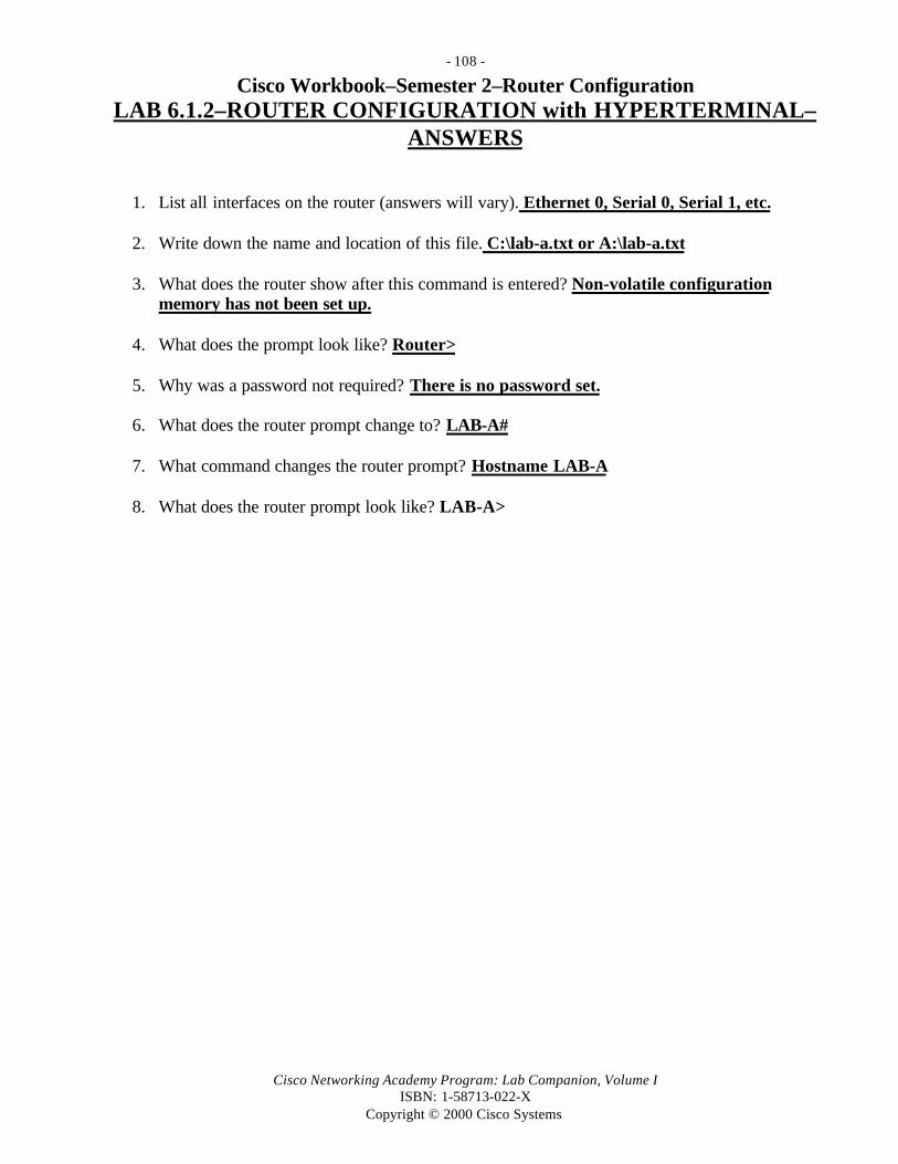
- 108 -
Cisco Networking Academy Program: Lab Companion, Volume IISBN: 1-58713-022-X
Copyright © 2000 Cisco Systems
Cisco Workbook–Semester 2–Router ConfigurationLAB 6.1.2–ROUTER CONFIGURATION with HYPERTERMINAL–
ANSWERS
1. List all interfaces on the router (answers will vary). Ethernet 0, Serial 0, Serial 1, etc.
2. Write down the name and location of this file. C:\lab-a.txt or A:\lab-a.txt
3. What does the router show after this command is entered? Non-volatile configurationmemory has not been set up.
4. What does the prompt look like? Router>
5. Why was a password not required? There is no password set.
6. What does the router prompt change to? LAB-A#
7. What command changes the router prompt? Hostname LAB-A
8. What does the router prompt look like? LAB-A>

- 109 -
Cisco Networking Academy Program: Lab Companion, Volume IISBN: 1-58713-022-X
Copyright © 2000 Cisco Systems
Cisco Labs–Semester 2–Router ConfigurationLAB 6.1.4–ROUTER CONFIGURATION TFTP–ANSWERS
1. What is the name of the configuration file you are writing on the TFTP server? (Answers willvary.) LAB-A-confg
2. What does the router show after this command is entered? Non-volatile configurationmemory has not been set up.
3. What does the prompt look like? Router>

- 110 -
Cisco Networking Academy Program: Lab Companion, Volume IISBN: 1-58713-022-X
Copyright © 2000 Cisco Systems
Cisco Labs–Semester 2–Router ConfigurationLAB 6.2.1–BASIC ROUTER CONFIGURATION–ANSWERS
1. What is the router command to view the current running configuration? show running-config(abbreviated sh run).
2. Compare the hostname in the running-config with the router prompt. Are they the same? Yes
3. Is the hostname the same as the router prompt for NVRAM? Yes
4. What does the router prompt look like? Router name(config)#
5. Is hostname one of the command options? Yes
6. What did the router respond with? WORD this system’s network name
7. Did the router’s prompt change to the new hostname? Yes
8. What is the router’s hostname? Your first name
9. Is the hostname the same as the router prompt? No (since you have not saved it yet)
10. What did the router say the message of the day is? This is the message of the day.
11. Is there a description name for interface serial0? No
12. What does the router prompt look like in interface configuration mode?Router name(config-if)#
13. What is the description for interface serial0? The description is what you typed in inStep 22.
14. Is the interface serial0 description the same as in Step 22? No (since you have not savedit yet)
15. What is the command to copy the current running configuration to the backup (start)configuration? copy running-config startup-config (abbreviated copy run start)

- 111 -
Cisco Networking Academy Program: Lab Companion, Volume IISBN: 1-58713-022-X
Copyright © 2000 Cisco Systems
Cisco Labs–Semester 2–Router ConfigurationLAB 6.2.5–ROUTER INTERFACE CONFIGURATION–ANSWERS
1. Fill in the following table.
Interface IP Address Subnet Mask
Ethernet0 219.17.100.1 255.255.255.0
Ethernet1 Not Present
Serial0 199.6.13.1 255.255.255.0
Serial1 201.100.11.2 255.255.255.0
Results of show running-config Command (output generated by a Cisco 2501 router)lab-b#show running-configBuilding configuration....Current configuration:!!version 11.1service slave-logservice udp-small-serversservice tcp-small-servers!hostname lab-b!boot system igs-j-l.111-5enable secret 5 $1$itif$vqTo8RC73KajshkzpFObr/enable password cisco!interface Ethernet0
ip address 219.17.100.1 255.255.255.0!interface Serial0
ip address 199.6.13.1 255.255.255.0bandwidth 56no fair-queueclockrate 56000
!interface Serial1
ip address 201.100.11.2 255.255.255.0ip access-group 1 out!
router igrp 100network 201.100.11.0

- 112 -
Cisco Networking Academy Program: Lab Companion, Volume IISBN: 1-58713-022-X
Copyright © 2000 Cisco Systems

- 113 -
Cisco Networking Academy Program: Lab Companion, Volume IISBN: 1-58713-022-X
Copyright © 2000 Cisco Systems
Results of show running-config Command–Continued (output generated by a Cisco2501)network 219.17.100.0network 199.6.13.0
ip host LAB-A 192.5.5.1 205.7.5.1 201.100.11.1ip host LAB-B 219.17.100.1 199.6.13.1 201.100.11.2ip host LAB-C 223.8.151.1 204.204.7.1 199.6.13.2ip host LAB-D 210.93.105.1 204.204.7.2ip host LAB-E 210.93.105.2no ip classless!line con 0exec-timeout 0 0--More--password ciscologinline aux 0line vty 0 4
password ciscologin
!end
2. Did all the interfaces ping successfully? Yes Note: If the other end of the WAN serial link(to the next router) is not configured correctly, or the other router is not powered on,you may not get a good ping result.
3. What does the router prompt look like? Router name(config)#
4. What does the router prompt look like? Router name(config-if)#
5. What does the router prompt look like? Router name(config)#
6. What does the router prompt look like? Router name#
7. What did the router say the IP address and subnet mask were for serial0? The IP and subnetmask for serial0 are the IP and subnet mask you typed in earlier.
8. What command will tell you how many and what kind of interfaces are on your router? showinterfaces from a user mode prompt or show running-config from a privileged modeprompt

- 114 -
Cisco Networking Academy Program: Lab Companion, Volume IISBN: 1-58713-022-X
Copyright © 2000 Cisco Systems
Cisco Labs–Semester 2–Router ConfigurationLAB 6.3.3–ROUTER PASSWORD RECOVERY–ANSWERS
1. What is the current configuration register setting? 0x2102
2. Why was no password required? The configuration file located in NVRAM was bypassed.The minimal configuration that the router starts up with has no passwords.
3. How does your router prompt change? The prompt changes from router# to LAB-A#,indicating that the running configuration has been changed.
4. What passwords do you see?enable secret 5 $1$miYV$i9OOuSBQBde5fzgS3tn8T0enable password cisco
5. What passwords do you now see?enable secret 5 $1$G6IE$1TkTp3lwYYwsQ2jV88ca9/enable password cisco
6. Has the encrypted password changed from the value in Step 9? Yes
7. What is the value of the configuration register? 0x42
8. What is the new value of the configuration register? 0x2102 (at next reload)
9. Has the configuration register changed back to the original value you recorded in Step 2? Yes

- 115 -
Cisco Networking Academy Program: Lab Companion, Volume IISBN: 1-58713-022-X
Copyright © 2000 Cisco Systems
Cisco Labs–Semester 2–Router ConfigurationLAB 6.4.1–ROUTER CONFIGURATION CHALLENGE–ANSWERS
None

- 116 -
Cisco Networking Academy Program: Lab Companion, Volume IISBN: 1-58713-022-X
Copyright © 2000 Cisco Systems
Cisco Labs–Semester 2–Router ConfigurationLAB 6.4.2–CISCO CONFIGMAKER–ANSWERS
1. What other router series can you configure with ConfigMaker?800, 1000, 1600, 1700, 2500, 2600, 3600, and 4000 series
2. What other connections can you configure using ConfigMaker?Ethernet, HDLC, PPP, frame relay, async, ISDN, ISDN leased line, voice line, VPN
3. What command was missing from ConfigMaker’s IOS configuration?Clocking signal for the DCE interface Serial0
4. What commands do you need to add to the router to add clocking?interface serial0clockrate 56000Both commands are needed on Lab-A, Lab-B, and Lab-C Serial0 interfaces.
Sample Configuration File for Router Lab-A Created by ConfigMaker
! ******************************************************************! Lab-A.cfg - Cisco router configuration file! Automatically created by Cisco ConfigMaker v2.4 Build 24! Wednesday, March 22, 2000, 09:39:30 AM! Hostname: Lab-A! Model: 2514! ******************************************************************service timestamps debug uptimeservice timestamps log uptimeservice password-encryptionno service tcp-small-serversno service udp-small-servers!hostname Lab-A!enable password class!no ip name-server!ip subnet-zerono ip domain-lookupip routing!interface Ethernet 0 no shutdown description connected to Hub1 ip address 192.5.5.1 255.255.255.0keepalive 10interface Ethernet 1

- 117 -
Cisco Networking Academy Program: Lab Companion, Volume IISBN: 1-58713-022-X
Copyright © 2000 Cisco Systems
no shutdown
Sample Configuration File for Router Lab-A–Continued
description connected to Switch ip address 205.7.5.1 255.255.255.0 keepalive 10!interface Serial 0 no shutdown description connected to Lab-B ip address 201.100.11.1 255.255.255.0 encapsulation hdlc!interface Serial 1 no description no ip address shutdown!router rip version 2 network 192.5.5.0 network 205.7.5.0 network 201.100.11.0 no auto-summary!ip classlessno ip http serversnmp-server community public ROno snmp-server locationno snmp-server contact!line console 0 exec-timeout 0 0 password cisco login!line vty 0 4 password cisco login!! The following commands are not recognized by Cisco ConfigMaker! and are therefore appended here.!interface s0clockrate 56000!
end

- 118 -
Cisco Networking Academy Program: Lab Companion, Volume IISBN: 1-58713-022-X
Copyright © 2000 Cisco Systems
Cisco Labs–Semester 2–Router ConfigurationLAB 6.4.3–ROUTER CONFIGURATION with a WEB BROWSER–
ANSWERS
1. What is the IP address of the Ethernet port? 192.5.5.1
2. What options are available? (Note that 2500 series routers do not have the ClickStart option.)
Telnet Show interfacesShow diagnostic log Monitor the routerConnectivity test Show tech-support
3. Which option on the router’s home page has the most suboptions? Monitor the router

- 119 -
Cisco Networking Academy Program: Lab Companion, Volume IISBN: 1-58713-022-X
Copyright © 2000 Cisco Systems
Cisco Labs–Semester 2–Router ConfigurationLAB 7.1.3–IOS IMAGE BOOT–ANSWERS
1. Is there any indication of the configuration register setting? No (use show version)
2. With the information that the router returns, answer the following questions (answers willvary):
a. What is the IOS version and rev level? Version 11.1, rev (7)AAb. What is the name of the system image (IOS) file? C1600-nsy-1.111-7.AAc. Where was the router IOS image booted from? Flash memoryd. What type of processor (CPU) and how much RAM does this router have? Cisco
CPA1600 (68360) processor (revision C) with 3584K/512K bytes of memorye. What kind of router (platform type) is this? Cisco 1600f. The router backup configuration file is stored in Non-Volatile Random Access Memory
(NVRAM). How much NVRAM does this router have? 8KB of non-volatileconfiguration memory
g. The router operating system (IOS) is stored in Flash memory. How much flash memorydoes this router have? 6144KB of processor board PCMCIA Flash (read-only)–approximately 6MB
h. What is the configuration register set to? 0x102 What boot type does this setting specify?Examine NVRAM for boot system commands, and then boot from Flash.
3. Assuming the config-register was currently set to 0x2102, write the configuration modecommands to specify that the IOS image should be loaded from:
a. Flash: config-register 0x2102b. ROM monitor: config register 0x2100c. ROM: config register 0x2101
Results of show version Command (Output generated by a Cisco 1601 router)lab-c>show versionCisco Internetwork Operating System SoftwareIOS (tm) 1600 Software (C1600-NSY-L), Version 11.1(7)AA, EARLY DEPLOYMENT RELEASESOFTWARE (fc2)Copyright (c) 1986-1996 by cisco Systems, Inc.Compiled Thu 24-Oct-96 05:24 by kuongImage text-base: 0x080202B8, data-base: 0x02005000
ROM: System Bootstrap, Version 11.1(10)AA, EARLY DEPLOYMENT RELEASE SOFTWARE(fc1)ROM: 1600 Software (C1600-BOOT-R), Version 11.1(10)AA, EARLY DEPLOYMENT RELEASESOFTWARE (fc1)lab-c uptime is 1 week, 2 days, 6 hours, 54 minutesSystem restarted by reloadSystem image file is “flash:c1600-nsy-l.111-7.AA”, booted via flash
cisco CPA1600 (68360) processor (revision C) with 3584K/512K bytes of memory.Processor board ID 04176122

- 120 -
Cisco Networking Academy Program: Lab Companion, Volume IISBN: 1-58713-022-X
Copyright © 2000 Cisco Systems
Bridging software.

- 121 -
Cisco Networking Academy Program: Lab Companion, Volume IISBN: 1-58713-022-X
Copyright © 2000 Cisco Systems
Results of show version Command–ContinuedX.25 software, Version 2.0, NET2, BFE and GOSIP compliant.Authorized for CiscoPro software set only.1 Ethernet/IEEE 802.3 interface.2 Serial(sync/async) network interfaces.System/IO memory with parity disabled8K bytes of non-volatile configuration memory.6144K bytes of processor board PCMCIA flash (Read ONLY)Configuration register is 0x102
4. If the router were in ROM monitor mode, what command would manually boot the Cisco IOSsoftware? From ROM monitor mode, manually boot the IOS with the b command.
5. Document the following information:a. How much Flash memory is available and used? 1506796 bytes available; 6881812
bytes usedb. What is the file that is stored in Flash memory? igs-j-1.111-5c. What is the size in bytes of the Flash memory? 8192K bytes
Results of show flash Command (output generated by a Cisco 2514 router)lab-b#show flash
System flash directory:File Length Name/status 1 6881748 igs-j-l.111-5[6881812 bytes used, 1506796 available, 8388608 total]8192K bytes of processor board System flash (Read/Write)
6. What parts of the IOS filename igs-j-1.111-5 identify the following:
a. Platform on which the image runs: igs (such as Cisco 1600 or 2500)b. Special capabilities: j (such as IP subset with IPX)c. Where the image runs and whether it has been zip-compressed: 1.111-5 (from Flash)
7. To specify a fallback boot sequence, write the configuration command to specify that the IOSimage should be loaded from:
a. Flash: boot system flash IOS-Filenameb. A TFTP server: boot system TFTP IOS-filename tftp-addressc. ROM: boot system rom Will this be a full IOS image? No
8. To ensure that these commands are available for the router to use the next time it is restarted,what command do you need to enter next? copy running-config startup-config

- 122 -
Cisco Networking Academy Program: Lab Companion, Volume IISBN: 1-58713-022-X
Copyright © 2000 Cisco Systems
Cisco Labs–Semester 2–Router ConfigurationLAB 7.3.5–IOS IMAGE BACKUP/RESTORE–ANSWERS
1. Document the following information from the show flash command:a. How much Flash memory is available and used? 6881812 bytes used; 1506796 bytes
availableb. What is the file that is stored in Flash memory? igs-j-1.111-5c. What is the size in bytes of the Flash memory? 8192KB
Results of show flash Command (output generated by a Cisco 2514 router)lab-a#show flash
System flash directory:File Length Name/status 1 6881748 igs-j-l.111-5[6881812 bytes used, 1506796 available, 8388608 total]8192K bytes of processor board System flash (Read/Write)
2. What was the result of the ping command? The ping was successful
Results of the ping Command (output generated by a Cisco 2514 router)LAB-A#ping 192.5.5.2
Type escape sequence to abort.Sending 5, 100-byte ICMP Echoes to 192.5.5.2, timeout is 2 seconds:!!!!!Success rate is 100 percent (5/5), round-trip min/avg/max = 1/2/4 ms
3. What is the default location for the TFTP server root directory?C:\PROGRAM FILES\CISCO SYSTEMS\CISCO TFTP SERVER
4. What was the IP address of the TFTP server? 192.5.5.2 (workstation IP–will vary)
5. What did you name the file that was written to the TFTP server? igs-j-l.111-5
6. How did the router respond when copying the file? Exclamation marks (!!!!!!!!!!!!!!!!!!!!!) 7. What is the size in bytes of the file that was written? 6,721KB

- 123 -
Cisco Networking Academy Program: Lab Companion, Volume IISBN: 1-58713-022-X
Copyright © 2000 Cisco Systems
Results of the copy flash tftp Command (output generated by a Cisco 2514 router)LAB-A#copy flash tftp
System flash directory:File Length Name/status 1 6881748 igs-j-l.111-5[6881812 bytes used, 1506796 available, 8388608 total]Address or name of remote host [255.255.255.255]? 192.5.5.2Source file name? igs-j-l.111-5 (NOTE: the letter after the j- is a lower case L)Destination file name [igs-j-l.111-5]?Verifying checksum for ‘igs-j-l.111-5’ (file # 1)... OKCopy ‘igs-j-l.111-5’ from Flash to server as ‘igs-j-l.111-5’? [yes/no]!!!!!!!!!!!!!!!!!!!!!!!!!!!!!!!!!!!!!!!!!!!!!!!!!!!!!!!!!!!!!!!!!!!!!!!!!!!!!!!!!!!!!!!!!!!!!!!!!!!!!!!!!!!!!!!!!!!!!!!!!!!!!!!!!!!!!!!!!!!!!!!!!!!!!!!!!!!!!!!!!!!!!!!!!!!!!!!!!!!!!!!!!!!!!!!!!!!!!!!!!!!!!!!!!!!!!!!!!!!!!!!!!!!!!!!!!!!!!!!!!!!!!!!!!!!!!!!!!!Upload to server doneFlash copy took 00:02:38 [hh:mm:ss]
8. If you are copying the same filename as you backed up, the router will prompt you tooverwrite the existing IOS image. Write some of the prompts and responses you saw on therouter screen.
Results of the copy tftp flash Command (output generated by a Cisco 2514 router)**** NOTICE ****Flash load helper v1.0This process will accept the copy options and then terminatethe current system image to use the ROM based image for the copy.Routing functionality will not be available during that time.If you are logged in via telnet, this connection will terminate.Users with console access can see the results of the copy operation. ---- ******** ----Proceed? [confirm]System flash directory:File Length Name/status 1 6881748 igs-j-l.111-5[6881812 bytes used, 1506796 available, 8388608 total]Address or name of remote host [192.5.5.2]?Source file name? igs-j-l.111-5Destination file name [igs-j-l.111-5]?Accessing file 'igs-j-l.111-5' on 192.5.5.2...Loading igs-j-l.111-5 from 192.5.5.2 (via Ethernet0): ! [OK]

- 124 -
Cisco Networking Academy Program: Lab Companion, Volume IISBN: 1-58713-022-X
Copyright © 2000 Cisco Systems
Results of the copy tftp flash Command–ContinuedErase flash device before writing? [confirm]Flash contains files. Are you sure you want to erase? [confirm]Copy ‘igs-j-l.111-5’ from server as ‘igs-j-l.111-5’ into Flash WITH erase? [yes/no] yes%SYS-5-RELOAD: Reload requested%SYS-4-CONFIG_NEWER: Configurations from version 11.1 may not be correctly understood.%FLH: igs-j-l.111-5 from 192.5.5.2 to flash ...
System flash directory:File Length Name/status 1 6881748 igs-j-l.111-5[6881812 bytes used, 1506796 available, 8388608 total]Accessing file 'igs-j-l.111-5' on 192.5.5.2...Loading igs-j-l.111-5 from 192.5.5.2 (via Ethernet0): ! [OK]Erasing device... eeeeeeeeeeeeeeeeeeeeeeeeeeeeeeee ...erasedLoading igs-j-l.111-5 from 192.5.5.2 (via Ethernet0): !!!!!!!!!!!!!!!!!!!!!!!!!!!!!!!!!!!!!!!!!!!!!!!!!!!!!!!!!!!!!!!!!!!!!!!!!!!!!!!!!!!!!!!!!!!!!!!!!!!!!!!!!!!!!!!!!!!!!!!!!!!!!!!!!!!!!!!!!!!!!!!!!!!!!!!!!!!!!!!!!!!!!!!!!!!!!!!!!!!!!!!!!!
(Note: Lots of exclamation marks here )!!!!!!!!!!!!!!!!!!!!!!!!!!!!!!!!!!!!!!![OK - 6881748/8388608 bytes]
Verifying checksum... OK (0x5D14)Flash copy took 0:03:28 [hh:mm:ss]%FLH: Re-booting system after downloadF3: 6674716+207000+264864 at 0x3000060

- 125 -
Cisco Networking Academy Program: Lab Companion, Volume IISBN: 1-58713-022-X
Copyright © 2000 Cisco Systems
Cisco Labs–Semester 2–Router ConfigurationLAB 8.1.2–ROUTER PASSWORD RECOVERY–ANSWERS
1. What is the current configuration register setting? 0x2102
2. Why was no password required? The configuration file located in NVRAM was bypassed.The minimal configuration that the router starts up with has no passwords.
3. How does your router prompt change? The prompt changes from router# to LAB-A#,indicating that the running configuration has been changed.
4. What passwords do you see?enable secret 5 $1$miYV$i9OOuSBQBde5fzgS3tn8T0enable password cisco
5. What passwords do you now see?enable secret 5 $1$G6IE$1TkTp3lwYYwsQ2jV88ca9/enable password cisco
6. Has the encrypted password changed from the value in Step 9? Yes
7. What is the value of the configuration register? 0x42
8. What is the new value of the configuration register? 0x2102 (at next reload)
9. Has the configuration register changed back to the original value you recorded in Step 2? Yes

- 126 -
Cisco Networking Academy Program: Lab Companion, Volume IISBN: 1-58713-022-X
Copyright © 2000 Cisco Systems
Cisco Labs–Semester 2–Router ConfigurationLAB 8.2.1–INDIVIDUAL ROUTER CONFIGURATION–ANSWERS
Students should be able to repetitively configure the practice lab. At the start of this section, youshould log on to each router in enable exec mode, issue the erase startup-config command, andissue the reload command. This will force the routers to come up with a blank configuration andallow the students to practice the skills they will need to pass the Semester 2 final lab exam. Beloware the detailed command sets that the students will have to master. All commands are provided forrouter Lab-A. A table of configuration settings for the other routers follows these instructions.
Router Lab-A (2514) Basic Configuration Commands (see the next table for other routers)Step Description/Explanation
Router CommandPrompt
IOS Command
Enable privileged mode Router> EnableConfigure (the router) fromterminal (keyboard)
Router# Config T
Name Router Lab-A
(the prompt will change)
Router(config)# Hostname LAB-A
Set privileged mode encrypted(secret) password to class
Lab-A(config)# Enable secret class
Set privileged mode textpassword (optional)
Lab-A(config)# Enable password cisco
Disable DNS lookup Lab-A(config)# No ip domain-lookup
Select E0 interface Lab-A(config)# Interface Ethernet0
Provide description for E0(optional on any interface)
Lab-A(config-if)# Description connected to LAN A
Set E0 IP address and subnetmask
Lab-A(config-if)# Ip address 192.5.5.1 255.255.255.0
Bring interface E0 up Lab-A(config-if)# No shutdown
Select E1 interface Lab-A(config)# Interface Ethernet1
Set E1 IP address and subnetmask
Lab-A(config-if)# Ip address 205.7.5.1 255.255.255.0
Bring interface E0 up Lab-A(config-if)# No shutdown
Select S0 interface Lab-A(config-if)# Interface Serial0
Set S0 IP address and subnetmask
Lab-A(config-if)# ip address 201.100.11.1 255.255.255.0
Set IGRP bandwidth metric Lab-A(config-if)# Bandwidth 56Set DCE clock synch at 56000 Lab-A(config-if)# Clock rate 56000Bring interface S0 up Lab-A(config-if)# no shutdown
!Select S1 interface (not used) Lab-A(config-if)# Interface Serial1
Set no IP address for S1 Lab-A(config-if)# No ip addressAdministratively shut down S1 Lab-A(config-if)# Shutdown

- 127 -
Cisco Networking Academy Program: Lab Companion, Volume IISBN: 1-58713-022-X
Copyright © 2000 Cisco Systems
Exit interface config mode Lab-A(config-if)# ExitRouter Lab-A (2514) Basic Configuration Commands–Continued
Start RIP routing protocol Lab-A(config)# Router rip
Specify directly connectednetwork for routing updates
Lab-A(config-router)# Network 192.5.5.0
Specify directly connectednetwork for routing updates
Lab-A(config-router)# Network 205.7.5.0
Specify directly connectednetwork for routing updates
Lab-A(config-router)# Network 201.100.11.0
Exit router config mode Lab-A(config-router)# Exit
Enable browser management Lab-A(config)# Ip http server
Define router host name table N/A N/ASpecify host table entry for Lab-A(with interface IP addresses)
Lab-A(config)# ip host Lab-A 192.5.5.1 205.7.5.1201.100.11.1
Specify host table entry for Lab-B(with interface IP addresses)
Lab-A(config)# ip host Lab-B 219.17.100.1 199.6.13.1201.100.11.2
Specify host table entry for Lab-C(with interface IP addresses)
Lab-A(config)# ip host Lab-C 223.8.151.1 204.204.7.1199.6.13.2
Specify host table entry for Lab-D(with interface IP addresses)
Lab-A(config)# ip host LAB-D 210.93.105.1204.204.7.2
Specify host table entry Lab-E(with interface IP addresses)
Lab-A(config)# ip host LAB-E 210.93.105.2
Disable classless IP routing Lab-A(config)# no ip classless
Configure console line
(direct attach to console port)
Lab-A(config)# Line con 0
Enable console login passwordchecking
Lab-A(config-line)# Login
Set user mode password forconsole connection login
Lab-A(config-line)# Password cisco
Configure telnet line(virtual terminal or VTY)
Lab-A(config-line)# Line vty 0 4
Enable telnet login passwordchecking
Lab-A(config-line)# Login
Set user mode password for telnetconnection login
Lab-A(config-line)# Password cisco
Save the current runningconfiguration to the startupconfiguration
Lab-A# Copy running-config startup-config

- 128 -
Cisco Networking Academy Program: Lab Companion, Volume IISBN: 1-58713-022-X
Copyright © 2000 Cisco Systems
1. Fill in the table below with IP interface information for each of the five routers.
Cisco Lab Router IP Configuration (answers from router diagram–your answers may vary)
Router Name Lab-A Lab-B Lab-C Lab-D Lab-E
Model Number 2514 2503 2503 2501 2501
Interface E0IP Address
192.5.5.1 219.17.100.1 223.8.151.1 210.93.105.1 210.93.105.2
Interface E0Subnet Mask
255.255.255.0 255.255.255.0 255.255.255.0 255.255.255.0 255.255.255.0
Interface E1IP Address
205.7.5.1 Not Present Not Present Not Present Not Present
Interface E1Subnet Mask
255.255.255.0 Not Present Not Present Not Present Not Present
Interface S0IP Address
201.100.11.1 199.6.13.1 204.204.7.1 Not Used Not Used
Interface S0Subnet Mask
255.255.255.0 255.255.255.0 255.255.255.0 Not Used Not Used
Interface S0* Clock Rate
56000 56000 56000 Not Used Not Used
Interface S1IP Address
Not Used 201.100.11.2 196.6.13.2 204.204.7.2 Not Used
Interface S1Subnet Mask
Not Used 255.255.255.0 255.255.255.0 255.255.255.0 Not Used
OtherInterface(s)
Console,AUX
ISDN BRI0,Console,AUX
ISDN BRI0,Console,AUX
Console,AUX
Console,AUX
* Note: Clock rate must be set on the DCE end (S0) of the WAN link between routers.

- 129 -
Cisco Networking Academy Program: Lab Companion, Volume IISBN: 1-58713-022-X
Copyright © 2000 Cisco Systems
Cisco Labs–Semester 2–Router ConfigurationLAB 9.4.2.1–SHOW ARP AND CLEAR ARP–ANSWERS
1. What three important pieces of information are displayed? IP address, MAC address, andwhat router interface this address pair lives out of.
2. a. What is the significance of entering ? at the router prompt? The ? will invoke the help
facility.b. Does the clear command appear as an option? Yes
3. Are there any entries in the ARP table? Yes
4. Looking at the IP address of the ARP entries, what are the entries for? TheEthernet interfaces on this router
Results of show arp Command (output generated by a Cisco 2514 router)lab-b#show arpProtocol Address Age (min) Hardware Address Type InterfaceInternet 219.17..100.1 --- 0000.0c3b.f3a6 ARPA Ethernet0Internet 205.7.5.1 --- 0000.0c3b.f3a7 ARPA Ethernet1
5. Are there any new entries in the ARP table? No
6. Are there any new entries in the ARP table? Yes. The last entry is aworkstation on the 219.117.100.0 network.
Results of show arp Command (answers will vary)lab-b#show arpProtocol Address Age (min) Hardware Address Type InterfaceInternet 219.17.100.1 --- 0000.0c3b.f3a6 ARPA Ethernet0Internet 219.17.100.2 03 00a0.cc26.e3e3 ARPA Ethernet0
7. Explain why there were no new entries in Step 8 but there were in Step 10.In Step 10 you used a Windows 9x workstation to ping across the router.The router will maintain an ARP entry only for its own Ethernetnetworks. In Step 8, when you pinged to the other routers, there were nonew entries, because you were using serial interfaces to ping from routerto router, and serial interfaces do not appear in ARP cache.
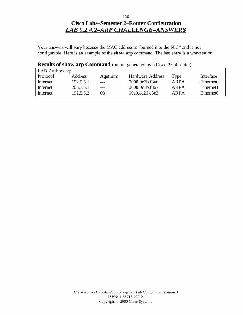
- 130 -
Cisco Networking Academy Program: Lab Companion, Volume IISBN: 1-58713-022-X
Copyright © 2000 Cisco Systems
Cisco Labs–Semester 2–Router ConfigurationLAB 9.2.4.2–ARP CHALLENGE–ANSWERS
Your answers will vary because the MAC address is “burned into the NIC” and is notconfigurable. Here is an example of the show arp command. The last entry is a workstation.
Results of show arp Command (output generated by a Cisco 2514 router)LAB-A#show arpProtocol Address Age(min) Hardware Address Type InterfaceInternet 192.5.5.1 --- 0000.0c3b.f3a6 ARPA Ethernet0Internet 205.7.5.1 --- 0000.0c3b.f3a7 ARPA Ethernet1Internet 192.5.5.2 03 00a0.cc26.e3e3 ARPA Ethernet0

- 131 -
Cisco Networking Academy Program: Lab Companion, Volume IISBN: 1-58713-022-X
Copyright © 2000 Cisco Systems
Cisco Labs–Semester 2–Router ConfigurationLAB X.X.X.X–NETWORK TROUBLESHOOTING CHALLENGE–
ANSWERS
Note: Answers will vary greatly, depending on which combination of problems are introduced.The most important thing is to write down which problems were introduced and where.

- 132 -
Cisco Networking Academy Program: Lab Companion, Volume IISBN: 1-58713-022-X
Copyright © 2000 Cisco Systems
Cisco Labs–Semester 2–Router ConfigurationLAB 10.1.4–IP ADDRESSING AND SUBNETS CHALLENGE–
ANSWERS
Answers are based on the standard five-router lab network topology. Your answers should bedifferent.
1. How many routers will you have? 5
2. Where will the routers be located? Should be at least 4 different geographical locations
3. How many switches will you have? 5
4. How many LANs are there? 5
5. How many WANs are there? 3
6. How many unique subnets will you need? 8
7. How many hosts per subnet (LAN and WAN) will you have? 2
8. How many IP addresses (hosts and router interfaces) will be required? 22 (10 workstationsand 12 router interfaces)
9. What is your Class C network address? 204.204.7.0
10. How many bits will you borrow from the host portion of the network address? 4
11. What will your subnet mask be? 255.255.255.240
12. How many total useable subnets will this allow for? 24 = 16 – 2 = 14
13. How many hosts per subnet will this allow for? 24 = 16 – 2 = 14
14. Which interfaces will require clock rate to be set? S0 on Lab-A, Lab-B, and Lab-C
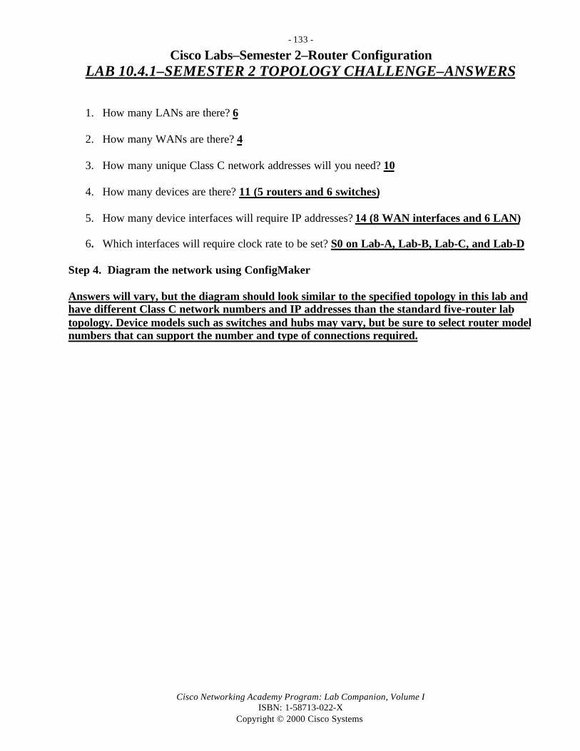
- 133 -
Cisco Networking Academy Program: Lab Companion, Volume IISBN: 1-58713-022-X
Copyright © 2000 Cisco Systems
Cisco Labs–Semester 2–Router ConfigurationLAB 10.4.1–SEMESTER 2 TOPOLOGY CHALLENGE–ANSWERS
1. How many LANs are there? 6
2. How many WANs are there? 4
3. How many unique Class C network addresses will you need? 10
4. How many devices are there? 11 (5 routers and 6 switches)
5. How many device interfaces will require IP addresses? 14 (8 WAN interfaces and 6 LAN)
6. Which interfaces will require clock rate to be set? S0 on Lab-A, Lab-B, Lab-C, and Lab-D
Step 4. Diagram the network using ConfigMaker
Answers will vary, but the diagram should look similar to the specified topology in this lab andhave different Class C network numbers and IP addresses than the standard five-router labtopology. Device models such as switches and hubs may vary, but be sure to select router modelnumbers that can support the number and type of connections required.

- 134 -
Cisco Networking Academy Program: Lab Companion, Volume IISBN: 1-58713-022-X
Copyright © 2000 Cisco Systems
Cisco Labs–Semester 2–Router ConfigurationLAB 12.1.5–STATIC ROUTES–ANSWERS
1. Did the router’s interface respond with a successful ping? Yes
2. Are there any routing protocol or static routes defined? Yes–RIP (answers will vary)
3. What does the router prompt look like? Router name(config)#
4. What was the router’s response? A.B.C.D destination prefix
5. What was the router’s response? A.B.C.D destination prefix mask
6. What was the router’s response? A.B.C.D forwarding router’s addressEthernet IEEE 802.3Null Null interfaceSerial Serial
7. What does the router prompt look like? Router name#
8. Was there an IP route with the static route you configured in the active configuration file? Yes
9. Was the neighboring router interface reachable? Yes

- 135 -
Cisco Networking Academy Program: Lab Companion, Volume IISBN: 1-58713-022-X
Copyright © 2000 Cisco Systems
Cisco Labs–Semester 2–Router ConfigurationLAB 12.3.5–RIP ROUTING–ANSWERS
1. Did all interfaces respond with a successful ping? Yes
2. Is there any routing protocol defined? No, but you will get a response from directlyconnected networks.
3. Are there any static routes defined? No. There should not be.
4. What does the router prompt look like? Router Name(config)#
5. What changed in the router prompt? Router Name(config-router)#
6. Is the router RIP protocol turned on and advertising the networks you defined? Yes
7. What does this command do? This command will copy the running configuration and saveit to the startup configuration so that the next time the reload command or router isturned off and back on, it will load the configuration that is running on the router now.
8. When is the next update due? 24 seconds
show IP protocol (output generated by a Cisco 2514 router)Lab-b# show ip protocol
Routing Protocol is “rip” Sending updates every 30 seconds, next due in 24 seconds Invalid after 180 seconds, hold down 180, flushed after 240 Outgoing update filter list for all interfaces is not set Incoming update filter list for all interfaces is not set Redistributing: rip Default version control: send version 1, receive any version Interface Send Recv Key-chain Ethernet0 1 1 2 Serial0 1 1 2 Serial1 1 1 2 Routing for Networks: 201.100.11.0 199.6.13.0 219.17.100.0 205.7.5.0 Routing Information Sources: Gateway Distance Last Update 201.100.11.1 120 00:00:15 199.6.13.2 120 00:00:17 Distance: (default is 120)

- 136 -
Cisco Networking Academy Program: Lab Companion, Volume IISBN: 1-58713-022-X
Copyright © 2000 Cisco Systems
9. How many routes were discovered by RIP? Four (answers will vary)show IP protocol (output generated by a Cisco 2514 router)LAB-B#show ip routeCodes: C - connected, S - static, I - IGRP, R - RIP, M - mobile, B - BGP D - EIGRP, EX - EIGRP external, O - OSPF, IA - OSPF inter area E1 - OSPF external type 1, E2 - OSPF external type 2, E - EGP i - IS-IS, L1 - IS-IS level-1, L2 - IS-IS level-2, * - candidate default U - per-user static route
Gateway of last resort is not set
R 204.204.7.0/24 [120/1] via 199.6.13.2, 00:00:09, Serial0R 223.8.151.0/24 [120/1] via 199.6.13.2, 00:00:09, Serial0C 201.100.11.0/24 is directly connected, Serial1C 219.17.100.0/24 is directly connected, Ethernet0R 192.5.5.0/24 [120/1] via 201.100.11.1, 00:00:04, Serial1C 199.6.13.0/24 is directly connected, Serial0R 210.93.105.0/24 [120/2] via 199.6.13.2, 00:00:09, Serial0
10. What information did you receive from this command? Status and global parametersassociated with an interface
show IP interface (output generated by a Cisco 2514 router)show ip interfaceEthernet0 is up, line protocol is up Internet address is 219.17.100.1/24 Broadcast address is 255.255.255.255 Address determined by setup command MTU is 1500 bytes Helper address is not set Directed broadcast forwarding is enabled Multicast reserved groups joined: 224.0.0.9 Outgoing access list is not set Inbound access list is not set Proxy ARP is enabled Security level is default Split horizon is enabled ICMP redirects are always sent ICMP unreachables are always sent ICMP mask replies are never sent IP fast switching is enabled IP fast switching on the same interface is disabled IP multicast fast switching is enabled Router Discovery is disabled IP output packet accounting is disabled IP access violation accounting is disabled TCP/IP header compression is disabled Probe proxy name replies are disabled

- 137 -
Cisco Networking Academy Program: Lab Companion, Volume IISBN: 1-58713-022-X
Copyright © 2000 Cisco Systems
show IP interface–Continued (output generated by a Cisco 2514 router) Gateway Discovery is disabled Policy routing is disabled Ethernet1 is up, line protocol is down Internet address is 205.7.5.1/24 Broadcast address is 255.255.255.255 Address determined by setup command MTU is 1500 bytes Helper address is not set Directed broadcast forwarding is enabled Multicast reserved groups joined: 224.0.0.9 Outgoing access list is not set Inbound access list is not set Proxy ARP is enabled Security level is default Split horizon is enabled ICMP redirects are always sent ICMP unreachables are always sent ICMP mask replies are never sent IP fast switching is enabled IP fast switching on the same interface is disabled IP multicast fast switching is enabled Router Discovery is disabled IP output packet accounting is disabled IP access violation accounting is disabled TCP/IP header compression is disabled Probe proxy name replies are disabled Gateway Discovery is disabled Policy routing is disabled Serial0 is up, line protocol is up Internet address is 199.6.13.1/24 Broadcast address is 255.255.255.255 Address determined by setup command MTU is 1500 bytes Helper address is not set Directed broadcast forwarding is enabled Multicast reserved groups joined: 224.0.0.9 Outgoing access list is not set Inbound access list is not set Proxy ARP is enabled Security level is default Split horizon is enabled ICMP redirects are always sent ICMP unreachables are always sent ICMP mask replies are never sent IP fast switching is enabled

- 138 -
Cisco Networking Academy Program: Lab Companion, Volume IISBN: 1-58713-022-X
Copyright © 2000 Cisco Systems
show IP interface–Continued (output generated by a Cisco 2514 router) IP fast switching on the same interface is enabled IP multicast fast switching is enabled Router Discovery is disabled IP output packet accounting is disabled IP access violation accounting is disabled TCP/IP header compression is disabled Probe proxy name replies are disabled Gateway Discovery is disabled Policy routing is disabled Serial1 is up, line protocol is up Internet address is 201.100.11.2/24 Broadcast address is 255.255.255.255 Address determined by setup command MTU is 1500 bytes Helper address is not set Directed broadcast forwarding is enabled Multicast reserved groups joined: 224.0.0.9 Outgoing access list is not set Inbound access list is not set Proxy ARP is enabled Security level is default Split horizon is enabled ICMP redirects are always sent ICMP unreachables are always sent ICMP mask replies are never sent IP fast switching is enabled IP fast switching on the same interface is enabled IP multicast fast switching is enabled Router Discovery is disabled IP output packet accounting is disabled IP access violation accounting is disabled TCP/IP header compression is disabled Probe proxy name replies are disabled Gateway Discovery is disabled Policy routing is disabled
11. What important information did you receive from this command? This command displaysRIP updates as they are sent and received.

- 139 -
Cisco Networking Academy Program: Lab Companion, Volume IISBN: 1-58713-022-X
Copyright © 2000 Cisco Systems
Cisco Labs–Semester 2–Router ConfigurationLAB 12.5.1–RIP CONVERGENCE–ANSWERS
1. Has the output from the command show ip route changed from when you issued thecommand in step 1? Yes
Lab-D#show ip routeCodes: C - connected, S - static, I - IGRP, R - RIP, M - mobile, B - BGP D - EIGRP, EX - EIGRP external, O - OSPF, IA - OSPF inter area N1 - OSPF NSSA external type 1, N2 - OSPF NSSA external type 2 E1 - OSPF external type 1, E2 - OSPF external type 2, E - EGP i - IS-IS, L1 - IS-IS level-1, L2 - IS-IS level-2, * - candidate default U - per-user static route, o - ODR
Gateway of last resort is not set
C 204.204.7.0/24 is directly connected, Serial1R 223.8.151.0/24 [120/1] via 204.204.7.1, 00:00:13, Serial1R 201.100.11.0/24 is possibly down, routing via 204.204.7.1, Serial1R 219.17.100.0/24 [120/2] via 204.204.7.1, 00:00:13, Serial1R 192.5.5.0/24 is possibly down, routing via 204.204.7.1, Serial1R 199.6.13.0/24 [120/1] via 204.204.7.1, 00:00:13, Serial1R 205.7.5.0/24 is possibly down, routing via 204.204.7.1, Serial1
2. What networks are inaccessible? 201.100.11.0, 192.5.5.0, and 205.7.5.0
3. Are the networks that were inaccessible in Question 2 listed in the output from the show iproute command? No. They have been dropped from the routing table.
Lab-D#sho ip routeCodes: C - connected, S - static, I - IGRP, R - RIP, M - mobile, B - BGP D - EIGRP, EX - EIGRP external, O - OSPF, IA - OSPF inter area N1 - OSPF NSSA external type 1, N2 - OSPF NSSA external type 2 E1 - OSPF external type 1, E2 - OSPF external type 2, E - EGP i - IS-IS, L1 - IS-IS level-1, L2 - IS-IS level-2, * - candidate default U - per-user static route, o - ODR
Gateway of last resort is not set
C 204.204.7.0/24 is directly connected, Serial1R 223.8.151.0/24 [120/1] via 204.204.7.1, 00:00:19, Serial1R 219.17.100.0/24 [120/2] via 204.204.7.1, 00:00:19, Serial1R 199.6.13.0/24 [120/1] via 204.204.7.1, 00:00:19, Serial1C 210.93.105.0/24 is directly connected, Ethernet0

- 140 -
Cisco Networking Academy Program: Lab Companion, Volume IISBN: 1-58713-022-X
Copyright © 2000 Cisco Systems
4. Do you see any information that would let you know that Lab-B’s serial 1 interface isdown? No
5. Why or why not? Static routes cannot be updated dynamically. Even with RIPrunning, it does not change the routing information of a static route, because staticroutes have a higher priority over a routing protocol that is dynamic.
6. Now that you have a good understanding of what static routes are, what are the benefits ofdynamic routes? The biggest advantage of dynamic routing is its ability to select analternate route or path when the route it was using becomes unavailable. This isknown as adjustment to network topology changes.
Points to keep in mind:
1. Manageability of dynamic routing2. Amount of information in routing updates as opposed to static routes3. Unmanageability of static routes4. Lower administrative distance. Trustworthy.
In the first scenario, you created a network that was running a dynamic routing protocol, RIP. Youcaused a change in the network, and you watched how long it took your network to realize thatchange and converge. In the second scenario, you created a network that was running both a routingprotocol and static routes concurrently. Again, you caused a change in the network, and you watchedhow long it took your network to realize the change and converge. In the first scenario, sometroubleshooting commands that you issued on one of the routers to see what was happening wereshow ip route and debug ip rip. You saw in the routing updates and in the routing table that a routewas down. Since you were running RIP, it took a while for it to finally converge. In other words, ittook RIP a while to make the route invalid, put it in holddown, and then flush it out. But RIP did allthat on its own. You did not have to go into each of the routers to reconfigure them so that thenetwork change could be realized and all the routers could converge. All the routers running RIPbasically converged on their own. On the other hand, in the second scenario, after you caused achange in the network and got into one of the routers to issue troubleshooting commands, you foundinformation that was of no use to you. In the updates, you did not find any inaccessible routes. In therouting table, there were no indications of routes that were down. You did not find any informationleading to a change in the network. Also with the second scenario, you had to configure each of therouters with static routes so that they could recognize the network. You basically configured thewhole network on each router. In the end, after a network change occurred, you got uselessinformation while debugging.

- 141 -
Cisco Networking Academy Program: Lab Companion, Volume IISBN: 1-58713-022-X
Copyright © 2000 Cisco Systems
This brings up four very important points:
1. Dynamic routing is easier and more efficient to configure on a router.
2. With dynamic routing, you do not have to monitor the network incessantly to figure out ifnetwork changes occurred. If they did occur, dynamic routing will realize the change andproperly converge.
3. With dynamic routing, when you issue a debug on the protocol, you find useful informationon what’s going on in the network. With static routes, you configure the whole network oneach router, and when it comes time to run a debug, you don’t receive information that youneed.
4. Static routes have a lower administrative distance. The reason is because it assumes that sincethe administrator himself/herself configured those routes, they should be flawless and given ahigher priority over a routing protocol that is dynamic. Even though static routes have a loweradministrative distance, they are more of a hassle to maintain, and during a debug, they do notprovide necessary information.

- 142 -
Cisco Networking Academy Program: Lab Companion, Volume IISBN: 1-58713-022-X
Copyright © 2000 Cisco Systems
Cisco Labs–Semester 2–Router ConfigurationLAB 12.5.2–ROUTING LOOPS CHALLENGE–ANSWERS
NONE

- 143 -
Cisco Networking Academy Program: Lab Companion, Volume IISBN: 1-58713-022-X
Copyright © 2000 Cisco Systems
Cisco Labs–Semester 2–Router ConfigurationLAB 12.5.3–ROUTING LOOPS PREVENTION CHALLENGE–
ANSWERS
1. How many updates did it take to converge? About 12 updates
2. How many updates did it take to converge? Less than 5 updates
3. Compare Questions 1 and 2 and explain why the network converged faster after youchanged the default metric. The maximum hop count is set to 10, so the router does nothave to wait for the hop count to reach 16 before it considers the networkunreachable. The timers were set to less than normal. Split horizon was enabled sothat convergence would occur more quickly.
Output from show ip protocol command shows default settings for RIP routing protocol timers.LAB-C#sho ip protoRouting Protocol is “rip” Sending updates every 30 seconds, next due in 9 seconds Invalid after 180 seconds, hold down 180, flushed after 240 Outgoing update filter list for all interfaces is not set Incoming update filter list for all interfaces is not set Redistributing: rip Default version control: send version 1, receive any version Routing for Networks: 223.8.151.0 204.204.7.0 199.6.13.0 Routing Information Sources: Gateway Distance Last Update Distance: (default is 120)
Understanding Timers
Update: The time between routing updates sent by a router.
Invalid: The term invalid is used for routes that have not been heard from for the period of timethat the invalid timer is set for. This means, for example, that if the invalid timer is set to 60, andan advertisement for a route from the router it was learned from has not been received for 61seconds, the invalid timer expires, and the route is considered invalid.
Holddown: The term holddown refers to routes that have been marked invalid but are not yetcapable of being replaced with a new route of a higher metric. This timer determines how longthe route is kept under holddown. While in holddown state, the router will keep sending updatesabout the route and will keep forwarding packets via that route until the holddown expires.

- 144 -
Cisco Networking Academy Program: Lab Companion, Volume IISBN: 1-58713-022-X
Copyright © 2000 Cisco Systems
Flush:The flush timer restarts every time an update is received for a route from the router that it islearned from. The flush and invalid timers restart at the same time and run concurrently. Whenthe flush timer expires for a route, the route is removed from the routing table. For RIP, the flushtimer expires before the holddown timer can expire.
Routing Loop Prevention Techniques
Split Horizon:Split horizon disables the router from sending information about a route in the routing tablethrough the same interface that it learned about the route from. For example, if Lab-B sendsinformation about Lab-E to Lab-A via its Ethernet 0, Lab-A will not send information aboutLab-E via Ethernet 0 back to Lab-B.
Poison Reverse:This is when a router informs its neighbors that routes that they were once capable of reachingvia a particular interface are no longer available because the interface has gone down. Routersreact to a poison reverse message by immediately placing the poisoned routes into holddowninstead of waiting for the invalid timer to expire. This saves convergence time, as much as 180seconds (default invalid timer), depending on how soon after a regular update a poison reverseupdate arrives.
Defining Default Metrics:Default metrics are set to disable counting to infinity. Counting to infinity causes routing loopsby incrementing a route that it cannot reach but believes its neighbor can. So every time a routethat is not reachable by one router is sent to its neighbors, routers that have not converged yet,that route’s metric increases by one. That keeps happening over and over again until the routersfinally converge. Default metric sets a metric count, where a route is allowed to propagate thenetwork a certain number of times before it is removed from the routing table.

- 145 -
Cisco Networking Academy Program: Lab Companion, Volume IISBN: 1-58713-022-X
Copyright © 2000 Cisco Systems
Cisco Labs–Semester 2–Router ConfigurationLAB 13.1.6.–TROUBLESHOOTING 5-ROUTER NETWORK–
ANSWERS
Possible Introduced Network Problems# Category Symptom Possible Problems Solution1 Router Can’t get from user to
exec modeUnknown enablepassword
Perform passwordrecovery procedure
2 Router Ping consistently failson one interface
Wrong IP address ormask entered on one endof the ping
While in interfacemode, properlyconfigure IP address
3 Router Ping test consistentlyfails on one interface
Interface is shut down Use no shutdown onthat interface
4 Router Can’t ping across aserial line
Clock rate not set onDCE end
Set clock rate on DCEend
5 Router Can’t ping across serialline
Clock rate is set on bothDCE and DTE ends
Clock rate shouldonly be set on DCEend
6 Router Typing router’s namedoesn’t substitute for itsIP address; connectiontimed out
Bad DNS entry Use IP host commandto fix IP address
7 Router Router won’t boot intouser mode
Config register has beenchanged
Change configregister to 0x2102
8 Router Router has blankconfiguration file evenwhen you show start
No configuration inNVRAM
Either in setup modeor line by line, createa router config
9 Router Wrong or empty routingtable
Wrong routing protocolenabled
Change routingprotocol with routerrip command
10 Router Wrong or empty routingtable
Wrong or missingnetworks when routingprotocol was enabled
Issue a proper routerrip and networkcommand
11 Router Router won’t even beginboot process
Router power unplugged,or power supply has aproblem
Plug in the router
12 Router Router is running alimited IOS
No IOS image in Flash oron TFTP server
Find a source for theIOS image and copyinto Flash
13 Router Can telnet to a router butcan’t get past itspassword
You have an incorrect vtypassword
Go to the router inquestion and look upthe vty password in itsconfiguration file
14 Workstation Can’t console into router Wrong settings onterminal emulationprogram
Enter correct settingsfor terminal emulationprogram

- 146 -
Cisco Networking Academy Program: Lab Companion, Volume IISBN: 1-58713-022-X
Copyright © 2000 Cisco Systems
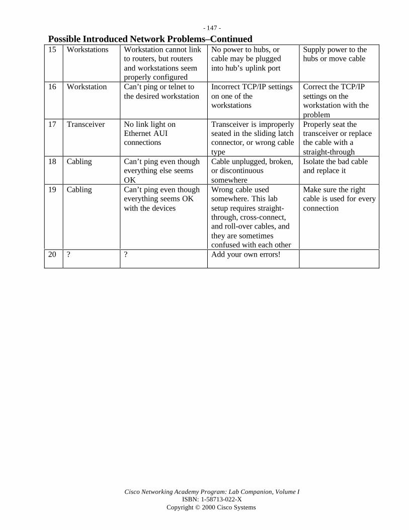
- 147 -
Cisco Networking Academy Program: Lab Companion, Volume IISBN: 1-58713-022-X
Copyright © 2000 Cisco Systems
Possible Introduced Network Problems–Continued15 Workstations Workstation cannot link
to routers, but routersand workstations seemproperly configured
No power to hubs, orcable may be pluggedinto hub’s uplink port
Supply power to thehubs or move cable
16 Workstation Can’t ping or telnet tothe desired workstation
Incorrect TCP/IP settingson one of theworkstations
Correct the TCP/IPsettings on theworkstation with theproblem
17 Transceiver No link light onEthernet AUIconnections
Transceiver is improperlyseated in the sliding latchconnector, or wrong cabletype
Properly seat thetransceiver or replacethe cable with astraight-through
18 Cabling Can’t ping even thougheverything else seemsOK
Cable unplugged, broken,or discontinuoussomewhere
Isolate the bad cableand replace it
19 Cabling Can’t ping even thougheverything seems OKwith the devices
Wrong cable usedsomewhere. This labsetup requires straight-through, cross-connect,and roll-over cables, andthey are sometimesconfused with each other
Make sure the rightcable is used for everyconnection
20 ? ? Add your own errors!


![11gR2 Upgrade Companion[1]](https://img.pdfslide.us/doc/110x75/55270b5155034622368b4634/11gr2-upgrade-companion1.jpg)

![A Companion to Bioethics[1][1]](https://img.pdfslide.us/doc/110x75/577d26fd1a28ab4e1ea2bfff/a-companion-to-bioethics11.jpg)


![Elementary Italian Companion[1]](https://img.pdfslide.us/doc/110x75/552b954d4a795931588b4747/elementary-italian-companion1.jpg)
