Embed Size (px)
Citation preview
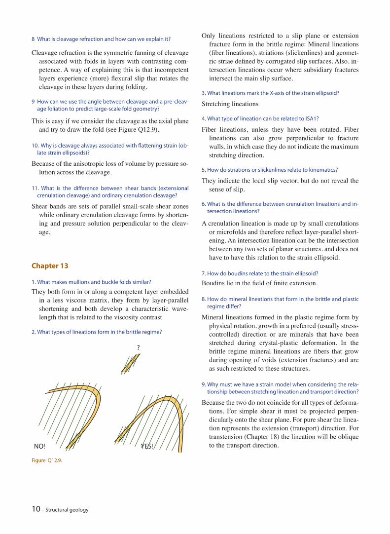
Answers to review questions in the book
On these pages you find the author’s answers to the review questions presented at the end of each book chapter. Hopefully they will be of help if you are uncertain about how to answer some of those questions. Any-way, some of the questions can be answered in different ways, so do not consider them as an absolute key. In general, when answering questions in structural geology (and most other fields within geology) sketches that in simple terms explain what you mean tend to be useful. A few are presented here, more could be added for more complete answers.
6. What is kinematic analysis?
Kinematic analysis is the analysis of particle movement without considering the forces or stresses that caused it (involving forces makes our analysis dynamic). It can be performed at any scale, from finding the sense of shear from a thin section image to determining nappe translations from kilometer-scale folds.
Chapter 2
1. What are the flow parameters discussed in this chapter?
Flow parameters describe the flow pattern at an in-stance, and are the flow apophyses, ISA (Instantaneous Stretching Axes) and the kinematic vorticity number (Wk).
2. What is the deformation called if flow parameters are constant throughout the deformation history?
Steady-state deformation.
3. Are ISA equal to stress axes?
Not exactly, but the two are closely related. ISA tells us how a rock instantaneously reacts to stress. For defor-mation involving small strains and for simple bound-ary conditions, such as in a deformation rig in a labo-ratory, the two can be considered to be identical. This will also be the case for a homogeneous medium that is exposed to linear-viscous (Newtonian) deformation (Chapter 6).
4. What is the difference between angular shear and shear strain?
The angular shear, ψ, describes the change in angle be-tween two originally perpendicular lines. The shear strain (γ) is simply the tangent to the angular shear strain (ψ): γ = tan ψ.
5. What is plane strain and where does it plot in the Flinn dia-gram?
Chapter 1
1. What is structural geology all about?
A big question that can be answered in many ways, but here is one attempt: Structural geology is about the structures, such as faults, shear zones and folds that form as the lithosphere deforms; and about the forces, stresses and processes that cause lithospheric deforma-tion.
2. Name the four principal ways a structural geologist can learn about structural geology and rock deformation. How would you rank them?
Field work, physical experiments, remote sensing (in-cluding seismic data), and numerical methods. Differ-ent geoscientists would rank them differently (depend-ing on their interest and experiment, but I would put field work first, and perhaps keep the order given in the previous sentence. Everything should somehow build on or relate to field studies.
3. How can we collect structural data sets? Name important data types that can be used for structural analysis.
Through conventional field work, from remote sens-ing data (satellite images, Lidar data sets and Google Earth), seismic data (3-D cubes are great!) and ex-perimental data. Magnetic and gravity data are usu-ally used together with other types of data, particularly field data and seismic data.
4. What are the advantages and disadvantages of seismic reflec-tion data sets?
Seismic data give the unique opportunity to study and map subsurface structures in three dimensions, but has a resolution issue (structures and beds below a certain limit are invisible).
5. What is a scale model?
A scale model is one where essential parameters, such as geometry, model size, gravity, friction, viscosity, strain rate etc. have proportionally been scaled down.
2 – Structural geology
Plane strain is where there is no shortening or extension perpendicular to the plane containing the maximum and minimum strain axes (X and Z), i.e. Y = 1. Hence (X/Y)/(Y/Z) = 1 and X/Z = 1 for constant volume plane strain, which plots along the main diagonal in the Flinn diagram. If volume change is involved plane strain plots along an offset diagonal.
6. Give examples of plane strain.
Simple shear, pure shear, subsimple shear.
7. What is meant by particle paths?
Paths or traces that particles outline over a time interval during the deformation history. It could be a portion of the history or the entire history of deformation.
8. What happens to the principal strain axes during pure shear-ing?
They remain fixed in space while they change length ac-cording to the equation X/Z = 1.
9. What is meant by the expression non-coaxial deformation his-tory?
It means that some or all of the three principal strain axes rotate during deformation.
10. What is the kinematic vorticity number?
The kinematic vorticity number describes the ratio be-tween the rate of rotation of strain axes during the deformation and the rate at which these axes change lengths.
11. What set of material lines do not rotate or change length dur-ing simple shear?
Those that lie within the shear plane (parallel to the shear zone boundaries).
Chapter 3 1. What is meant by the term strain markers? Give examples.
Strain markers are any visual expression in a deformed rock that allow us to identify changes in shapes and orientations caused by strain. They can be linear or may represent areas or volumes. For strain markers to be useful we must know or make some assumption about their pre-deformational shape, length, or orienta-tion.
2. What information can we get out of linear or planar strain markers?
Linear markers may express changes in length (e.g. boudinaged minerals, belemnites etc.) and/or orienta-
tion. Two related sets of linear markers, such as fossil symmetry lines of brachiopods, can give us angular shear strain.
3. What is the effect of a viscosity (competence) difference be-tween strain markers and the matrix?
Viscosity contrast may cause objects to deform different-ly from the matrix. Hence, the strain that we get from the objects is not representative for the bulk strain.
4. How can we deal with pre-deformational fabrics, for example in conglomerate pebbles?
If all the objects (pebbles) had the same orientation be-fore deformation we have a problem. We can only use the Rf/φ-method if there are some pebbles that initial-ly had orientations different from the majority of the clasts. We then have to rely on independent knowledge about the pre-deformational fabric, such as observa-tion outside of a shear zone.
5. What is needed to find shear strain in a rock?
We need two lines that were orthogonal prior to the de-formation to define shear strain. The shear strain is the tangent to the angular shear strain, which is the change in angle between the two originally perpendicular lines.
6. Give some serious concerns (pitfalls) regarding strain analysis.
• There must be no viscosity contrast (see Question 3.3)• There may be an initial fabric that must be accounted
for, which is not always easy (Question 3.4). • Strain must be homogeneous at the scale of data collec-
tion (a prerequisite) – a condition that is rarely fulfilled to the full extent.
• Measuring the orientation of section(s) relative to prin-cipal strain axes involves an uncertainty. In most cases, two-dimensional strain analyses is done in the section to represent one of the principal strain planes.
7. How can we find three-dimensional strain from a deformed conglomerate?
By finding strain from at least two of the three principal planes, or by finding strain from at least three arbitrarily oriented planes (at relative high angles to each other).
8. Shear zones are an expression of heterogeneous strain. How can we perform strain analyses in shear zones?
We must look at areas or volumes that are small enough that strain can be treated as homogeneous.
9. What is meant by passive and active strain markers?
Passive strain markers have no viscosity contrast with the matrix, while active ones do. See Question 3.
Answers to review questions in the book – 3
10. What is meant by strain partitioning in this context?
When viscosity contrast causes objects to deform differ-ently from the matrix, the strain is partitioned between the matrix and the strain objects.
Chapter 4
1. When is it appropriate to use the term pressure in geology?
Pressure should be used when considering a fluid, where there is no shear stress. Pressure is correctly used about pore fluids and magma, but also about salt, which over geologic time behaves more or less like a fluid. Meta-morphic petrologists also use pressure when describing the general pressure resulting from rock overburden in the crust, thus implicitely relating to the hydrostatic or lithostatic model.
2. How can we graphically visualize the state of stress in two and three dimensions?
By using the Morh diagram and the Mohr circle.
3. Where could we expect to find tensional stress in the crust? In general, tensional stresses can only occur close to the
surface, above a few hundred meters depth. As an extra bit of information, the depth zmax at which a downward-propagating tension fracture can exist can be shown to be given by the equation:
z Tgmax =3 0
ρ
Where T0 is the tensile strength and r is the density of the rock. Realistic values of T0 is 1 – 6 MPa, which for r = 2300 kg/m3 implies that tension fractures cannot exist deeper than about 130 – 800 m. They may how-ever turn into shear fractures or faults at these depths. Deeper down tensional stresses can only occur very lo-cally, notably at crack tips where fluid pressure is high (strongly overpressured layers).
4. How will the shape and orientation of the stress ellipsoid change if we define a different coordinate system?
None of them will change.
5. Will the stress tensor (matrix) look different if we choose a dif-ferent coordinate system?
Yes, it will look different, but its eigenvectors and eigen-values will remain the same.
6. A diagonal tensor has numbers on the diagonal running from the upper left to the lower right corner, with all other entries being zero. What does a diagonal stress tensor imply?
That the coordinate axes of our coordinate system paral-lel the principal stress axes (or vice versa).
7. If the diagonal entries in a diagonal stress matrix are equal, what does the stress ellipsoid look like, and what do we call this state of stress?
The stress ellipsoid will be a sphere, and the state of stress is isotropic.
8. If we apply a stress vector at various angles to a given surface, at what angle is the shear stress at its maximum? How does that compare to applying a force (also a vector) to the same surface, i.e. at what orientation would the shear component of the force be maximized?
The shear stress is at its maximum when oriented at 45° to the surface, while the shear force is at its maximum when parallel to the surface. See Figure 4.2b.
Chapter 5
1. How can we get information about the stress field near the surface? Some kilometers down? Even deeper down?
Near the surface: Overcoring measurements, but also the orientation of recent fractures or fault scarps from earthquakes, fold axes and fissures associated with volcanism can indicate the orientation of the least horizontal principal stress. Some kilometers down (in wells): Borehole breakouts estimated from dipmeter or well imaging tools, hydraulic fracturing, overcoring (less common and more difficult). Deeper down focal mechanisms give stress information.
2. Which of the three reference states of stress are, by nature, iso-tropic?
The lithostatic reference state of stress is isotropic in the sense that the stress is the same in all directions.
3. Is the uniaxial-strain reference state a stress or strain state? How are stress and strain related in this model?
It is a state of stress controlled or prescribed by a given strain condition, which is that of compaction. When a rock compacts under the weight of the overburden without being able to expand in the horizontal direc-tion, stresses arise.
4. What physical factors controls the state of stress in a rock that is being uplifted through the upper crust?
There are two important effects: The thermal and the Poisson effects, both of which tend to decrease the horizontal stress. The thermal or cooling effect is re-lated to the cooling of rocks as they ascend. Cooling causes the rock to contract and potentially fracture.
4 – Structural geology
In general, a strike-slip regime, but extensional in releas-ing bends and compressional regime in restraining bends (see Chapter 18).
12. Why does the differential stress increase downwards in the brittle crust?
Because it is more difficult to fracture a rock under con-fining pressure than an unconfined rock. The deeper down in the upper crust, the more stress can build up before it fractures (yields). Thus the strength increases downwards through the brittle crust, until crystal-plas-tic mechanisms kick in at the brittle-plastic transition.
13. If we increase the fluid pressure in a sandstone unit, will the effective stress increase or decrease?
If we look at Equation 5.2 it is obvious that increasing pf reduces the effective stress. This is because an elevated fluid pressure helps lifting the overburden so that the stress across grain contacts becomes smaller.
Chapter 6
1. What is the difference between rheology and rock mechanics?
Rheology has more to do with how rocks flow over geo-logic time as a continuum, while rock mechanics also deals with how rocks fracture along sharp discontinui-ties.
2. What is a constitutive law or equation?
A constitutive law is a mathematical equation that relates stress and strain.
3. What does isotropic mean?
An isotropic medium is one that has the same mechanical properties in all directions, so that it reacts identically to stress regardless of its orientation.
4. What is an elastic material?
An elastic medium is one that reacts to stress by accumu-lating recoverable strain, which means that it returns to its pre-deformational shape once the stress is removed.
5. What is an incompressible medium, and what is its Poisson’s ratio?
An incompressible medium maintains its volume dur-ing deformation. Poisson’s ratio is the ratio between the extensions normal and parallel to the axis of major compressive stress.
6. Some media are easier to elastically bend, stretch or shorten than others – we could say that there is a difference in stiffness. What constants describe the stiffness of an elastic material or its resistance against elastic deformation?
The Poisson effect is related to the change in pressure from removal of overburden: Poisson effect is the ratio of the horizontal strain and vertical extension, or the “reluctancy” of a rock to contract perpendicular to the vertical extension. The relevant equation in the book is (5.6):
σ σ νν
σν
αH h vE T= =
−
+−
1 1
∆ ∆
where the first term is the Poisson effect and the second is the thermal effect.
5. Why does sandstone fracture more easily than shale when up-lifted?
A sandstone has different elastic properties than shale, and it reacts as a stronger and more brittle rock.
6. How can we define tectonic stress?
Tectonic stress is the deviation from the reference stress or expected stress caused by tectonic processes.
7. What conditions must apply for Anderson’s classification of tectonic stress to be strictly valid?
Anderson’s assumptions: One of the principal stresses is vertical and strain is coaxial.
8. What is the differential stress at 5 km depth for continental crust if we have a perfect lithostatic state of stress?
There is no differential stress at any depth for perfect lithostatic stress, since all the principal stresses are al-ways equal.
9. What forces related to plate tectonics can cause tectonic stress?
Slab pull, ridge push, collisional resistance and basal drag (frictional drag along the base of the lithosphere).
10. Why do we find evidence of strike-slip and normal fault stress regimes in addition to the thrust-fault regime in active (con-tractional) orogens such as the Himalaya and Andes?
There could be many reasons for this. Here are some: Many orogenic belts result from slightly oblique con-vergence, which is partitioned into pure contraction and localized strike-slip motion (strike-slip faults). Strike-slip faults may also result from blocks escap-ing laterally during convergence. Elevated parts of the orogen may collapse gravitationally to form normal faults.
11. What stress regime(s) would we expect along strike-slip faults, such as the San Andreas Fault?
Answers to review questions in the book – 5
Young’s modulus, which is simply stress over strain.
7. What is the yield stress and what happens if it is exceeded?
The yield stress is the stress level (elastic limit) at which a rock accumulates permanent strain, either through brittle or plastic deformation (or both).
8. What is the difference between linear elastic and linear vis-cous?
Linear elastic means that the stress-strain curve is linear so that, at any point on the curve, a given increase in stress yields a fixed increase in strain. Linear viscuous means that stress is linearly related to strain rate, so that higher stress means faster flow and strain accu-mulation.
9. What types of materials are truly viscous? What parts of the Earth can be modeled as being viscous?
Fluids are truly viscous. The asthenospheric mantle is considered to be viscous.
10. What does it mean that a rock layer is more competent than its neighboring layers?
It means that it has a higher viscosity than its surround-ings and therefore is more resistive to flow.
11. What could cause strain softening and strain hardening in a deforming rock?
Strain softening is promoted by growth of platy miner-als, reduction in grain size, increased fluid pressure, recrystallization into newer and weaker minerals and an increase in temperature. Strain hardening may be caused by accumulation of dislocations, cementation, geometric interlocking of grains or structures and much more.
12. What is the difference between plastic deformation and creep?
Plastic deformation is not strain-rate sensitive. Creep does not involve strain hardening or softening.
13. What controls the locations of brittle–plastic transitions in the lithosphere?
This is the transition between brittle and plastic deforma-tion mechanisms at the microscale, which is controlled by temperature, to a lesser extent by pressure, and to a large extent by mineralogy. Also, “dry” rocks will behave in a brittle manner at higher temperatures than “wet” rocks. Strain rate also has some influence, where rapid strain accumulation more easily results in brittle deformation.
Chapter 7
1. What is the difference between cataclastic and granular flow?
Granular flow involves frictional sliding along grain con-tact surfaces and grain rotation and preserves grains from internal deformation. Cataclastic flow is destruc-tive because it also involves extensive microfracturing of grains.
2. What is frictional sliding?
Frictional sliding is mechanical sliding along a surface where frictional forces must be overcome. Another type of sliding, known as grain boundary sliding, oc-curs by means of diffusion in the crystal-plastic (non-frictional) regime.
3. What is the process zone that is located at the tip of shear frac-tures?
The process zone ahead of shear fractures is a zone or volume of microcracks that soften the rock and eases fracture propagation.
4. What is the difference between fractures and deformation bands?
Deformation bands (tabular discontinuities) are thicker than fractures with comparable offsets (sharp disconti-nuities). Bands do not accumulate more than cm-scale offsets while fractures can show meter-scale offsets or more. Fractures show a loss of cohesion, while most deformation bands preserve cohesion or are mechani-cally stronger than the host rock.
5. Why do not shear fractures form at 45° to σ1, where the re-solved shear stress is at its maximum?
This is explained in Box 7.2, where it is illustrated how shear fracture initiation or reactivation is controlled not only by shear stress (which is at its maximum at the plane oriented at 45° to σ1), but also by the normal stress (high normal stress counteracts slip). The ideal balance between these two effects is found at an angle higher than 45°.
6. What is a wing crack and how do they form?
A wing crack is an extension fracture that shoots off one side of a fracture near its tip zone if the fracture is re-activated in shear (at very small strains). They occur on the extensional side near the tips of the fracture and indicate sense of slip.
7. What structures can be found on joints that can reveal their growth history?
Joints may show the elliptical arrest lines or hesitation lines that indicate paleo-fracture tip lines and the plu-mose or feather-like hackles that indicate the propaga-
6 – Structural geology
Shear fractures are single structures, commonly referred to as surfaces but with a very small thickness (gener-ally <1 mm). A fault is a more composite structure with a thicker zone of strongly deformed rocks (the fault core) in which there may be one or more slip surfaces. A fault also contains a damage zone of deformation bands and/or fractures where strain is much lower than in the fault core.
2. Why do normal faults tend to be steeper than reverse faults?
While the shear stress is greatest at 45° to a fracture, the balance between shear and normal stress components makes fractures slip most easily at around 30° to σ1. Since σ1 is vertical for normal faults the expected dip becomes ~ 60°. Similarly, for reverse faults formed with σ1 being horizontal, the dip should be around 30°.
3. What is the main differences between a mylonite and a cata-clasite?
A mylonite forms as a result of predominantly crystal-plastic deformation (see Chapter 10), while a cataclas-ite is the result of cataclasis (grain fracturing, frictional sliding and grain rotation). Hence, the two form in the plastic and brittle (or frictional) regimes, respectively.
4. A vertical well drills through a part of the stratigraphic section twice (repeated section). What type of fault can we infer, and why can we not explain this by folding?
This characterizes a reverse fault. Isoclinal folding would also represent a repeated stratigraphy, but the stratigra-phy in the inverted limb would be inverted.
5. Why would the damage zone grow during faulting?
The damage zone tends to grow during faulting due to geometrical complications such as interlocking of faults, fault bends, lense formations in the fault, exten-sive cementation and more.
6. Would the damage zone be visible on good 3-D seismic data?
In general we are not able to see any seismic response from or image of the damage zone, although the noise generated along faults may overshadow such signals. Only wide damage zones with deformation structures that strongly alter the velocity structure of the rock may yield a seismic response strong enough that we may hope to see it on (future) high-resolution images.
7. How can dipmeter data help identifying faults?
Dipmeter data can show the abrupt changes in strike and (particularly) dip that occur as we drill through faults. In some cases dipmeter tools may pick up fracture and deformation band orientations and show a concentra-tion of those in the damage zone.
tion direction. Hackles are perpendicular to the arrest lines.
8. What does it mean that a rock is critically stressed?
A critically stressed rock is at the verge of brittle failure. Any increase in stress level will make it fracture.
9. What is a failure envelope and how is it established for a rock?
A failure envelope is the surface in Mohr space that de-scribes the critical stress for a range of shear stress and normal stress. It tangents the Mohr circles found for experiments carried out at various confining pressure, and ideally the tangent points are the points of failure during the experiments.
10. What is meant by the term Griffith cracks, and how do they affect rock strength and fracture propagation?
The term stems from A. Griffith, who considered natural rocks to be flawed by the presence of microcracks. He modeled such microcracks as elliptically shaped fea-tures with very large aspect ratios, and they have since been referred to as Griffith cracks. The presence of Griffith cracks weakens a rock and helps explain why the theoretical strength of an unflawed rock is much higher than the strength estimated from experiments. Favorably oriented Griffith cracks (those with high shear stress) are expected to grow faster than others and to link up to form a through-going mesoscopic fracture in the rock.
11. Why are large rock samples weaker than small samples of the same rock?
Large rock samples are generally weaker because they are more likely to contain larger flaws with orienta-tions that decrease the rock strength more than the flaws in smaller rock samples. Hence it is all a matter of probability.
12. What is the coefficient of sliding friction and what is a repre-sentative value for this coefficient for the brittle crust?
The coefficient of sliding friction is the friction coeffi-cient on a preexisting fracture surface, and this value is always lower than the internal friction version of the same rock. Existing fracture surfaces control the strength of the upper crust and the coefficient is given by Byerlee’s laws, which tell us that it is 0.6 for most of the brittle crust, and 0.85 at shallow depths (σs < 200).
Chapter 8
1. What is the difference between shear fractures and faults?
Answers to review questions in the book – 7
The reduced stress tensor is one that contains informa-tion about the orientations of the principal stresses and their relative (but not absolute) magnitudes. Hence, the reduced stress tensor gives us the orientation and shape of the stress ellipsoid.
Chapter 10
1. What is the difference between a slip plane in a plastically de-forming crystal and a slip plane associated with brittle fault-ing?
A slip plane in the brittle crust is a plane along which there is or has been frictional sliding so that the rock is permanently destroyed. A slip plane in a plastically deforming crystal is much smaller (it occurs within a grain at the atomic scale) and heals continuously with-out loosing strength. Intercrystalline plastic slip im-plies movement of a dislocation front within a plane in the crystal, and such a slip plane is usually the plane in a crystal that has the highest density of atoms.
2. What are the main principal differences between brittle and plastic deformation?
The two differ in terms of microscale deformation pro-cesses (mechanisms): Brittle deformation occurs through brittle (frictional) processes (cataclasis, rigid rotation and frictional sliding) while plastic deforma-tion occurs by diffusion and dislocation creep.
3. Why is intracrystalline fracturing so common in brittle defor-mation of highly porous rocks?
Intracrystalline means within (rather than between) crys-tals. In highly porous rocks the stress that builds up across grain – grain contacts become large because the forces are distributed across very small areas (stress is force per area), which makes them fracture internally more easily than if the porosity was small or nonexis-tent.
4. Name two plastic deformation mechanisms that can operate at shallow crustal depths.
Twinning (for example in calcite) and wet diffusion, also called pressure solution (typical in carbontates and some quartzites).
5. What is meant by the term dislocation creep and how does it differ from diffusion?
Dislocation creep is the formation, motion and destruc-tion of linear defects in the crystal lattice while diffu-
8. Is fault sealing good or bad in terms of petroleum exploration and production?
Large sealing faults are generally good because they can contribute to a trap. Many traps rely on sealing faults. However, small sealing faults within an oil field can cause trouble during water injection and hydrocarbon production because they compartmentalize the reser-voir and necessitate more wells and better knowledge of smaller faults and their properties. Such knowledge is extremely difficult to get if the faults are subseismic.
Chapter 9
1. Why must we be careful when interpreting lineations as dis-placement indicators?
Lineations may not be representative of the displacement we are after, because they may represent only the last minor displacement of the fault, possibly a late reacti-vation that has nothing to do with the main fault move-ment.
2. What are the premises for successful paleostress analysis?
Paleostress analysis is based on the assumptions that all the faults included in the analysis formed in the same stress field, that the rock is homogeneous, the strain is low and the structures did not rotate since their forma-tion (or that the rotation can be accounted for).
3. What is meant by the expression “slip inversion”?
Slip inversion means reconstructing the orientation and shape of the stress ellipsoid (finding the stress matrix) from measured fault slip data (the orientation of fault planes, their lineation and sense of slip for a number of differently oriented fault planes).
4. What are conjugate faults, and what stress information do they give?
Conjugate faults are faults whose acute angle bisects σ1. They form at the same time in the same stress field. Hence, they give the orientation of σ1, σ3 (their line of intersection) and therefore also of σ1 (perpendicular to the others).
5. What does the Wallace – Bott hypothesis postulate?
The Wallace – Bott hypothesis postulates that slip on a planar fracture occurs along the greatest resolved shear stress on that plane.
6. What is the reduced stress tensor?
8 – Structural geology
3. How can we distinguish between flexural flow and orthogonal flexure?
Flexural flow folds show increasing strain away from the hinge, where the strain is zero. There is no neutral sur-face, but the strain is ideally identical across the layer-ing. Orthogonal flexure folds have a neutral surface, with strain also in the hinge zone (extension in upper part, contraction below the neutral surface).
4. How would we identify a buckle fold?
Folding is restricted to a competent layer in a less compe-tent matrix, with the folds rapidly dying out away from the competent layer. The folds are periodic, meaning that they have a characteristic wavelength. This char-acteristic wavelength is longer for thick layers than for thin ones. Buckle folds are parallel (Class 1B) folds with a neutral surface.
5. A shear fold?
Shear folds are similar (Class 2) folds with no compe-tence contrast between folded layers. Shear folds tend to be harmonic.
6. What is the difference between a parallel and a similar fold?
Parallel folds (Class 1B) have constant layer thickness, similar folds have constant thickness parallel to the axial trace and therefore have attenuated limbs.
7. What fold types are parallel?
Ideal buckle folds, orthogonal flexure folds, flexural slip folds and flexural flow folds.
sion is about point defects, notably vacancies, and how they move through the crystal during deformation.
6. What deformation mechanism is particularly active in fine-grained rocks at high temperatures (in the lower crust and the mantle)?
Grain boundary sliding, previously referred to as super-plastic creep.
7. What information can we get from dynamically deformed quartz that disappears during static recrystallization?
The oblique fabric that forms constantly during dynamic (synkinematic) recrystallization of quartz disappears during static recrystallization. The oblique fabric gives information about sense of shear and possibly the in-stantaneous stretching direction and therefore Wk.
8. What is the difference between recrystallization by subgrain rotation and grain boundary migration?
Subgrain rotation recrystallization occurs by rotation of subgrains until the misfit angle is larger than 10°. Grain boundary migration implies that the boundaries move into grains with higher dislocation densities, so that unstrained grains expand on behalf of strained grains.
Chapter 11
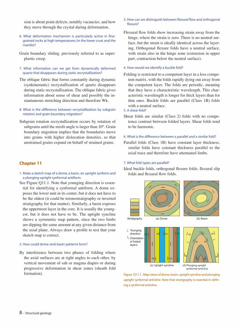
1. Make a sketch map of a dome, a basin, an upright synform and a plunging upright synformal antiform.
See Figure Q11.1. Note that younging direction is essen-tial for identifying a synformal antiform. A dome ex-poses the lower unit in its center, but it does not have to be the oldest (it could be tetonostratigraphy or inverted stratigraphy for that matter). Similarly, a basin exposes the uppermost layer in the core. It is usually the young-est, but it does not have to be. The upright syncline shows a symmetric map pattern, since the two limbs are dipping the same amount at any given distance from the axial plane. Always draw a profile to test that your sketch map is correct.
2. How could dome-and-basin patterns form?
By interference between two phases of folding where the axial surfaces are at right angles to each other, by vertical movement of salt or magma diapirs or during progressive deformation in shear zones (sheath fold formation). Figure Q11.1. Map views of dome, basin, upright syncline and plunging
upright synformal anticline. Note that stratigraphy is essential in defin-
ing a synformal anticline.
(a) Dome
(c) Upright syncline (d) Plunging upright synformal anticline
Stratigraphy
YoungingdirectionOrientationof foldedlayers
(b) Basin
30 3050
35 35
353030
35 35
5050
50
50 50
Answers to review questions in the book – 9
Primary foliations are primary planar structures such as bedding and magmatic layering. Secondary foliations form later, and tectonic foliations are secondary folia-tions that are related to tectonic processes. Almost all secondary foliations are tectonic.
2. How are primary foliations recognized in deformed and meta-morphosed sedimentary rocks?
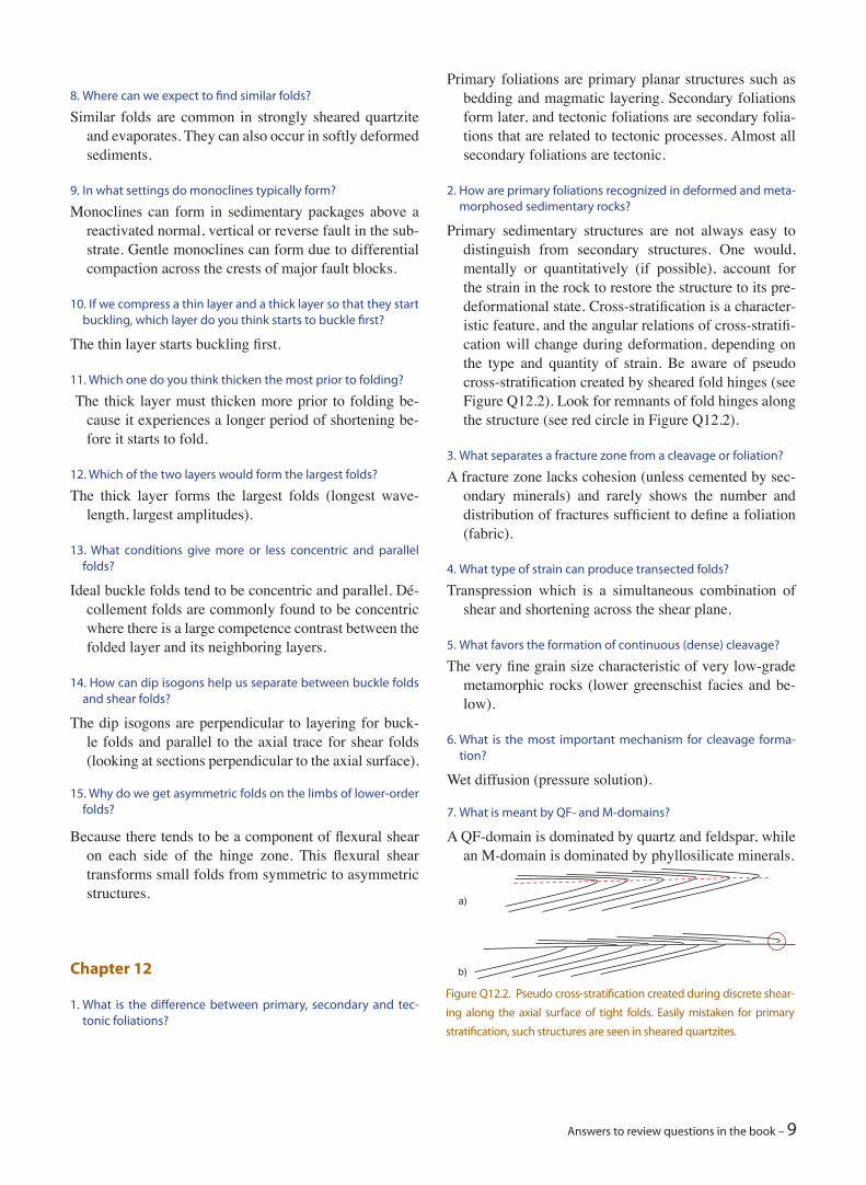
Primary sedimentary structures are not always easy to distinguish from secondary structures. One would, mentally or quantitatively (if possible), account for the strain in the rock to restore the structure to its pre-deformational state. Cross-stratification is a character-istic feature, and the angular relations of cross-stratifi-cation will change during deformation, depending on the type and quantity of strain. Be aware of pseudo cross-stratification created by sheared fold hinges (see Figure Q12.2). Look for remnants of fold hinges along the structure (see red circle in Figure Q12.2).
3. What separates a fracture zone from a cleavage or foliation?
A fracture zone lacks cohesion (unless cemented by sec-ondary minerals) and rarely shows the number and distribution of fractures sufficient to define a foliation (fabric).
4. What type of strain can produce transected folds?
Transpression which is a simultaneous combination of shear and shortening across the shear plane.
5. What favors the formation of continuous (dense) cleavage?
The very fine grain size characteristic of very low-grade metamorphic rocks (lower greenschist facies and be-low).
6. What is the most important mechanism for cleavage forma-tion?
Wet diffusion (pressure solution).
7. What is meant by QF- and M-domains?
A QF-domain is dominated by quartz and feldspar, while an M-domain is dominated by phyllosilicate minerals.
8. Where can we expect to find similar folds?
Similar folds are common in strongly sheared quartzite and evaporates. They can also occur in softly deformed sediments.
9. In what settings do monoclines typically form?
Monoclines can form in sedimentary packages above a reactivated normal, vertical or reverse fault in the sub-strate. Gentle monoclines can form due to differential compaction across the crests of major fault blocks.
10. If we compress a thin layer and a thick layer so that they start buckling, which layer do you think starts to buckle first?
The thin layer starts buckling first.
11. Which one do you think thicken the most prior to folding?
The thick layer must thicken more prior to folding be-cause it experiences a longer period of shortening be-fore it starts to fold.
12. Which of the two layers would form the largest folds?
The thick layer forms the largest folds (longest wave-length, largest amplitudes).
13. What conditions give more or less concentric and parallel folds?
Ideal buckle folds tend to be concentric and parallel. Dé-collement folds are commonly found to be concentric where there is a large competence contrast between the folded layer and its neighboring layers.
14. How can dip isogons help us separate between buckle folds and shear folds?
The dip isogons are perpendicular to layering for buck-le folds and parallel to the axial trace for shear folds (looking at sections perpendicular to the axial surface).
15. Why do we get asymmetric folds on the limbs of lower-order folds?
Because there tends to be a component of flexural shear on each side of the hinge zone. This flexural shear transforms small folds from symmetric to asymmetric structures.
Chapter 12
1. What is the difference between primary, secondary and tec-tonic foliations?
Figure Q12.2. Pseudo cross-stratification created during discrete shear-
ing along the axial surface of tight folds. Easily mistaken for primary
stratification, such structures are seen in sheared quartzites.
a)
b)
10 – Structural geology
Only lineations restricted to a slip plane or extension fracture form in the brittle regime: Mineral lineations (fiber lineations), striations (slickenlines) and geomet-ric striae defined by corrugated slip surfaces. Also, in-tersection lineations occur where subsidiary fractures intersect the main slip surface.
3. What lineations mark the X-axis of the strain ellipsoid?
Stretching lineations
4. What type of lineation can be related to ISA1?
Fiber lineations, unless they have been rotated. Fiber lineations can also grow perpendicular to fracture walls, in which case they do not indicate the maximum stretching direction.
5. How do striations or slickenlines relate to kinematics?
They indicate the local slip vector, but do not reveal the sense of slip.
6. What is the difference between crenulation lineations and in-tersection lineations?
A crenulation lineation is made up by small crenulations or microfolds and therefore reflect layer-parallel short-ening. An intersection lineation can be the intersection between any two sets of planar structures, and does not have to have this relation to the strain ellipsoid.
7. How do boudins relate to the strain ellipsoid?
Boudins lie in the field of finite extension.
8. How do mineral lineations that form in the brittle and plastic regime differ?
Mineral lineations formed in the plastic regime form by physical rotation, growth in a preferred (usually stress-controlled) direction or are minerals that have been stretched during crystal-plastic deformation. In the brittle regime mineral lineations are fibers that grow during opening of voids (extension fractures) and are as such restricted to these structures.
9. Why must we have a strain model when considering the rela-tionship between stretching lineation and transport direction?
Because the two do not coincide for all types of deforma-tions. For simple shear it must be projected perpen-dicularly onto the shear plane. For pure shear the linea-tion represents the extension (transport) direction. For transtension (Chapter 18) the lineation will be oblique to the transport direction.
8 What is cleavage refraction and how can we explain it?
Cleavage refraction is the symmetric fanning of cleavage associated with folds in layers with contrasting com-petence. A way of explaining this is that incompetent layers experience (more) flexural slip that rotates the cleavage in these layers during folding.
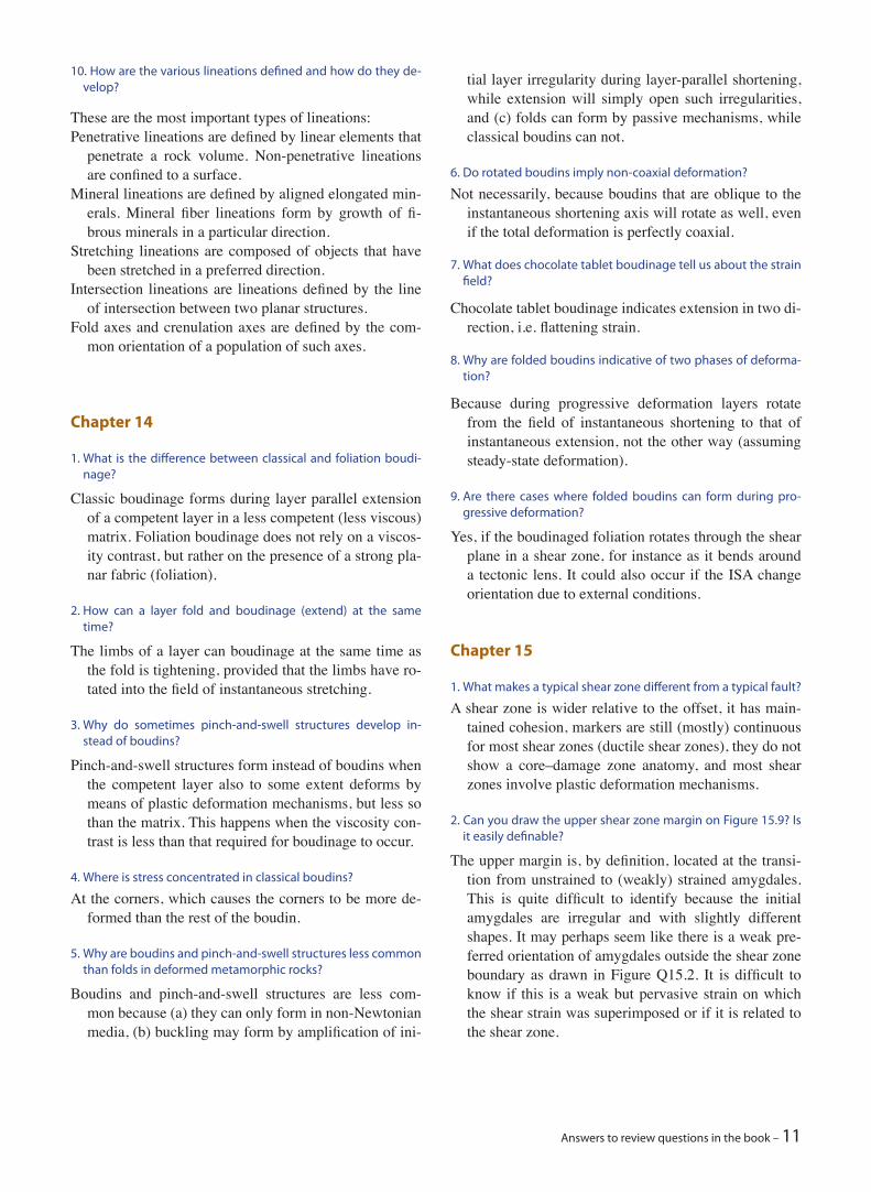
9 How can we use the angle between cleavage and a pre-cleav-age foliation to predict large-scale fold geometry?
This is easy if we consider the cleavage as the axial plane and try to draw the fold (see Figure Q12.9).
10. Why is cleavage always associated with flattening strain (ob-late strain ellipsoids)?
Because of the anisotropic loss of volume by pressure so-lution across the cleavage.
11. What is the difference between shear bands (extensional crenulation cleavage) and ordinary crenulation cleavage?
Shear bands are sets of parallel small-scale shear zones while ordinary crenulation cleavage forms by shorten-ing and pressure solution perpendicular to the cleav-age.
Chapter 13
1. What makes mullions and buckle folds similar?
They both form in or along a competent layer embedded in a less viscous matrix, they form by layer-parallel shortening and both develop a characteristic wave-length that is related to the viscosity contrast
2. What types of lineations form in the brittle regime?
NO!
?
YES!
Figure Q12.9.
Answers to review questions in the book – 11
tial layer irregularity during layer-parallel shortening, while extension will simply open such irregularities, and (c) folds can form by passive mechanisms, while classical boudins can not.
6. Do rotated boudins imply non-coaxial deformation?
Not necessarily, because boudins that are oblique to the instantaneous shortening axis will rotate as well, even if the total deformation is perfectly coaxial.
7. What does chocolate tablet boudinage tell us about the strain field?
Chocolate tablet boudinage indicates extension in two di-rection, i.e. flattening strain.
8. Why are folded boudins indicative of two phases of deforma-tion?
Because during progressive deformation layers rotate from the field of instantaneous shortening to that of instantaneous extension, not the other way (assuming steady-state deformation).
9. Are there cases where folded boudins can form during pro-gressive deformation?
Yes, if the boudinaged foliation rotates through the shear plane in a shear zone, for instance as it bends around a tectonic lens. It could also occur if the ISA change orientation due to external conditions.
Chapter 15
1. What makes a typical shear zone different from a typical fault?
A shear zone is wider relative to the offset, it has main-tained cohesion, markers are still (mostly) continuous for most shear zones (ductile shear zones), they do not show a core–damage zone anatomy, and most shear zones involve plastic deformation mechanisms.
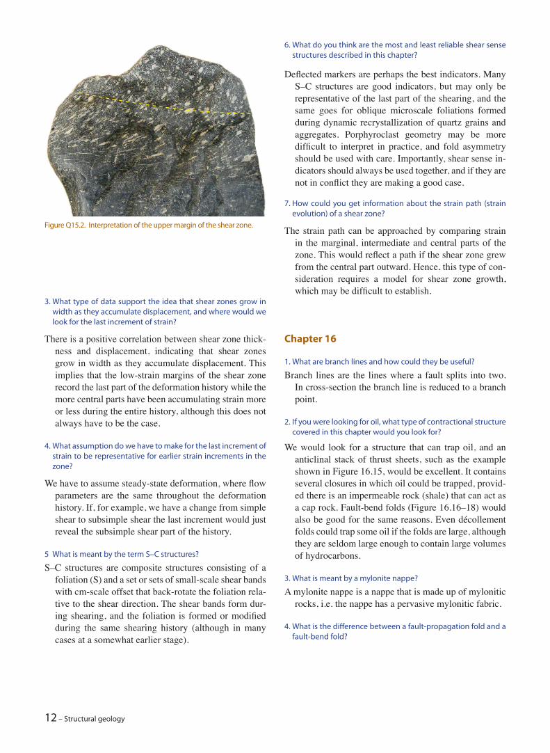
2. Can you draw the upper shear zone margin on Figure 15.9? Is it easily definable?
The upper margin is, by definition, located at the transi-tion from unstrained to (weakly) strained amygdales. This is quite difficult to identify because the initial amygdales are irregular and with slightly different shapes. It may perhaps seem like there is a weak pre-ferred orientation of amygdales outside the shear zone boundary as drawn in Figure Q15.2. It is difficult to know if this is a weak but pervasive strain on which the shear strain was superimposed or if it is related to the shear zone.
10. How are the various lineations defined and how do they de-velop?
These are the most important types of lineations:Penetrative lineations are defined by linear elements that
penetrate a rock volume. Non-penetrative lineations are confined to a surface.
Mineral lineations are defined by aligned elongated min-erals. Mineral fiber lineations form by growth of fi-brous minerals in a particular direction.
Stretching lineations are composed of objects that have been stretched in a preferred direction.
Intersection lineations are lineations defined by the line of intersection between two planar structures.
Fold axes and crenulation axes are defined by the com-mon orientation of a population of such axes.
Chapter 14
1. What is the difference between classical and foliation boudi-nage?
Classic boudinage forms during layer parallel extension of a competent layer in a less competent (less viscous) matrix. Foliation boudinage does not rely on a viscos-ity contrast, but rather on the presence of a strong pla-nar fabric (foliation).
2. How can a layer fold and boudinage (extend) at the same time?
The limbs of a layer can boudinage at the same time as the fold is tightening, provided that the limbs have ro-tated into the field of instantaneous stretching.
3. Why do sometimes pinch-and-swell structures develop in-stead of boudins?
Pinch-and-swell structures form instead of boudins when the competent layer also to some extent deforms by means of plastic deformation mechanisms, but less so than the matrix. This happens when the viscosity con-trast is less than that required for boudinage to occur.
4. Where is stress concentrated in classical boudins?
At the corners, which causes the corners to be more de-formed than the rest of the boudin.
5. Why are boudins and pinch-and-swell structures less common than folds in deformed metamorphic rocks?
Boudins and pinch-and-swell structures are less com-mon because (a) they can only form in non-Newtonian media, (b) buckling may form by amplification of ini-
12 – Structural geology
6. What do you think are the most and least reliable shear sense structures described in this chapter?
Deflected markers are perhaps the best indicators. Many S–C structures are good indicators, but may only be representative of the last part of the shearing, and the same goes for oblique microscale foliations formed during dynamic recrystallization of quartz grains and aggregates. Porphyroclast geometry may be more difficult to interpret in practice, and fold asymmetry should be used with care. Importantly, shear sense in-dicators should always be used together, and if they are not in conflict they are making a good case.
7. How could you get information about the strain path (strain evolution) of a shear zone?
The strain path can be approached by comparing strain in the marginal, intermediate and central parts of the zone. This would reflect a path if the shear zone grew from the central part outward. Hence, this type of con-sideration requires a model for shear zone growth, which may be difficult to establish.
Chapter 16
1. What are branch lines and how could they be useful?
Branch lines are the lines where a fault splits into two. In cross-section the branch line is reduced to a branch point.
2. If you were looking for oil, what type of contractional structure covered in this chapter would you look for?
We would look for a structure that can trap oil, and an anticlinal stack of thrust sheets, such as the example shown in Figure 16.15, would be excellent. It contains several closures in which oil could be trapped, provid-ed there is an impermeable rock (shale) that can act as a cap rock. Fault-bend folds (Figure 16.16–18) would also be good for the same reasons. Even décollement folds could trap some oil if the folds are large, although they are seldom large enough to contain large volumes of hydrocarbons.
3. What is meant by a mylonite nappe?
A mylonite nappe is a nappe that is made up of mylonitic rocks, i.e. the nappe has a pervasive mylonitic fabric.
4. What is the difference between a fault-propagation fold and a fault-bend fold?
3. What type of data support the idea that shear zones grow in width as they accumulate displacement, and where would we look for the last increment of strain?
There is a positive correlation between shear zone thick-ness and displacement, indicating that shear zones grow in width as they accumulate displacement. This implies that the low-strain margins of the shear zone record the last part of the deformation history while the more central parts have been accumulating strain more or less during the entire history, although this does not always have to be the case.
4. What assumption do we have to make for the last increment of strain to be representative for earlier strain increments in the zone?
We have to assume steady-state deformation, where flow parameters are the same throughout the deformation history. If, for example, we have a change from simple shear to subsimple shear the last increment would just reveal the subsimple shear part of the history.
5 What is meant by the term S–C structures?
S–C structures are composite structures consisting of a foliation (S) and a set or sets of small-scale shear bands with cm-scale offset that back-rotate the foliation rela-tive to the shear direction. The shear bands form dur-ing shearing, and the foliation is formed or modified during the same shearing history (although in many cases at a somewhat earlier stage).
Figure Q15.2. Interpretation of the upper margin of the shear zone.
Answers to review questions in the book – 13
Chapter 17
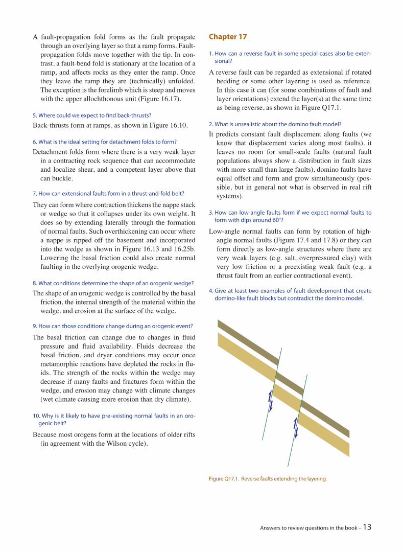
1. How can a reverse fault in some special cases also be exten-sional?
A reverse fault can be regarded as extensional if rotated bedding or some other layering is used as reference. In this case it can (for some combinations of fault and layer orientations) extend the layer(s) at the same time as being reverse, as shown in Figure Q17.1.
2. What is unrealistic about the domino fault model?
It predicts constant fault displacement along faults (we know that displacement varies along most faults), it leaves no room for small-scale faults (natural fault populations always show a distribution in fault sizes with more small than large faults), domino faults have equal offset and form and grow simultaneously (pos-sible, but in general not what is observed in real rift systems).
3. How can low-angle faults form if we expect normal faults to form with dips around 60°?
Low-angle normal faults can form by rotation of high-angle normal faults (Figure 17.4 and 17.8) or they can form directly as low-angle structures where there are very weak layers (e.g. salt, overpressured clay) with very low friction or a preexisting weak fault (e.g. a thrust fault from an earlier contractional event).
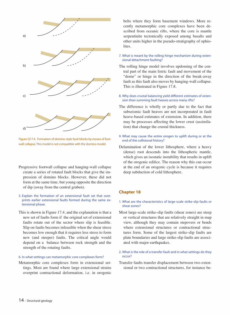
4. Give at least two examples of fault development that create domino-like fault blocks but contradict the domino model.
A fault-propagation fold forms as the fault propagate through an overlying layer so that a ramp forms. Fault-propagation folds move together with the tip. In con-trast, a fault-bend fold is stationary at the location of a ramp, and affects rocks as they enter the ramp. Once they leave the ramp they are (technically) unfolded. The exception is the forelimb which is steep and moves with the upper allochthonous unit (Figure 16.17).
5. Where could we expect to find back-thrusts?
Back-thrusts form at ramps, as shown in Figure 16.10.
6. What is the ideal setting for detachment folds to form?
Detachment folds form where there is a very weak layer in a contracting rock sequence that can accommodate and localize shear, and a competent layer above that can buckle.
7. How can extensional faults form in a thrust-and-fold belt?
They can form where contraction thickens the nappe stack or wedge so that it collapses under its own weight. It does so by extending laterally through the formation of normal faults. Such overthickening can occur where a nappe is ripped off the basement and incorporated into the wedge as shown in Figure 16.13 and 16.25b. Lowering the basal friction could also create normal faulting in the overlying orogenic wedge.
8. What conditions determine the shape of an orogenic wedge?
The shape of an orogenic wedge is controlled by the basal friction, the internal strength of the material within the wedge, and erosion at the surface of the wedge.
9. How can those conditions change during an orogenic event?
The basal friction can change due to changes in fluid pressure and fluid availability. Fluids decrease the basal friction, and dryer conditions may occur once metamorphic reactions have depleted the rocks in flu-ids. The strength of the rocks within the wedge may decrease if many faults and fractures form within the wedge, and erosion may change with climate changes (wet climate causing more erosion than dry climate).
10. Why is it likely to have pre-existing normal faults in an oro-genic belt?
Because most orogens form at the locations of older rifts (in agreement with the Wilson cycle).
Figure Q17.1. Reverse faults extending the layering.
14 – Structural geology
belts where they form basement windows. More re-cently metamorphic core complexes have been de-scribed from oceanic rifts, where the core is mantle serpentinite tectonically exposed among basalts and other units higher in the pseudo-stratigraphy of ophio-lites.
7. What is meant by the rolling hinge mechanism during exten-sional detachment faulting?
The rolling hinge model involves updoming of the cen-tral part of the main listric fault and movement of the “dome” or hinge in the direction of the break-away fault as this fault also moves by hanging-wall collapse. This is illustrated in Figure 17.8.
8. Why does crustal balancing yield different estimates of exten-sion than summing fault heaves across many rifts?
The difference is wholly or partly due to the fact that subseismic fault heaves are not incorporated in fault heave-based estimates of extension. In addition, there may be processes affecting the lower crust (assimila-tion) that change the crustal thickness.
9. What may cause the entire orogen to uplift during or at the end of the collisional history?
Delamination of the lower lithosphere, where a heavy (dense) root descends into the lithospheric mantle, which gives an isostatic instability that results in uplift of the orogenic edifice. The reason why this can occur at the end of an orogenic cycle is because it requires deep subduction of cold lithosphere.
Chapter 18
1. What are the characteristics of large-scale strike-slip faults or shear zones?
Most large-scale strike-slip faults (shear zones) are steep or vertical structures that are relatively straight in map view, although they may contain stepovers or bends where extensional structures or contractional struc-tures form. Some of the largest strike-slip faults are plate boundaries and large strike-slip faults are associ-ated with major earthquakes.
2. What is the role of a transfer fault and in what settings do they occur?
Transfer faults transfer displacement between two exten-sional or two contractional structures, for instance be-
Progressive footwall collapse and hanging-wall collapse create a series of rotated fault blocks that give the im-pression of domino blocks. However, these did not form at the same time, but young opposite the direction of dip (away from the central graben).
5. Explain the formation of an extensional fault set that over-prints earlier extensional faults formed during the same ex-tensional phase.
This is shown in Figure 17.4, and the explanation is that a new set of faults form if the original set of extensional faults rotate out of the sector where slip is feasible. Slip on faults becomes infeasible when the shear stress becomes low enough that it requires less stress to form new (and steeper) faults. The critical angle would depend on a balance between rock strength and the strength of the rotating faults.
6. In what settings can metamorphic core complexes form?
Metamorphic core complexes form in extensional set-tings. Most are found where large extensional strains overprint contractional deformation, i.e. in orogenic
a)
b)
c)
d)
Figure Q17.4. Formation of domino-style fault blocks by means of foot-
wall collapse. This model is not compatible with the domino model.
Answers to review questions in the book – 15
8. Like Death Valley, the Dead Sea is a place where you can walk on dry land below sea level, and an apparently unmotivated “hole in the ground” along a strike-slip fault. How do you think it formed?
The Dead Sea is a releasing bend or a stepover between two strike-slip fault segments.
9. How can strike-slip faults accommodate large-scale pure shear?
Strike-slip faults arranged in conjugate sets can accom-modate large-scale pure shear.
Chapter 19
1. Why does diapirism not initiate as a result of density inversion alone?
The overburden is generally too strong, so the overburden must fracture or fault before diapirism can initiate.
2. What is meant by reactive diapirism and in what tectonic regime(s) can it occur?
Reactive diapirism means salt rising as a diapir due to tec-tonic deformation. This occurs most easily during ex-tension, in which case space is easily provided so that salt can ascend. Compression can modify (squeeze) existing diapirs but is less likely to initiate diapirs.
3. What is it about classic centrifuge models that in some ways makes them unrealistic?
Classic centrifuge models model both the salt and the overburden as fluids, while the overburden should be modeled as a frictional material.
4. What is the difference between active and passive diapirism and how can we distinguish between them?
During active diapirism the salt forces its way upward through the overburden, driven by some sort of load-ing, for example differential loading (a heavier load next to the diapir making salt flow into the diapir). In passive diapirism diapirs continually rise as sediments are deposited around them. The crest of passive dia-pirs are at or close to the surface while active diapirs may be deeper. Active diapirs show evidence of force-ful intrusion by means of rotated flaps of what was once roof layers, while layers around passive diapirs are only gently rotated due to compactional effects that may create minibasins next to the salt structure.
5. What is meant by the expression “downbuilding”?
tween two normal faults, two graben segments or two thrust faults.
3. What type of structures form where a strike-slip fault makes a stepover or an abrupt bend?
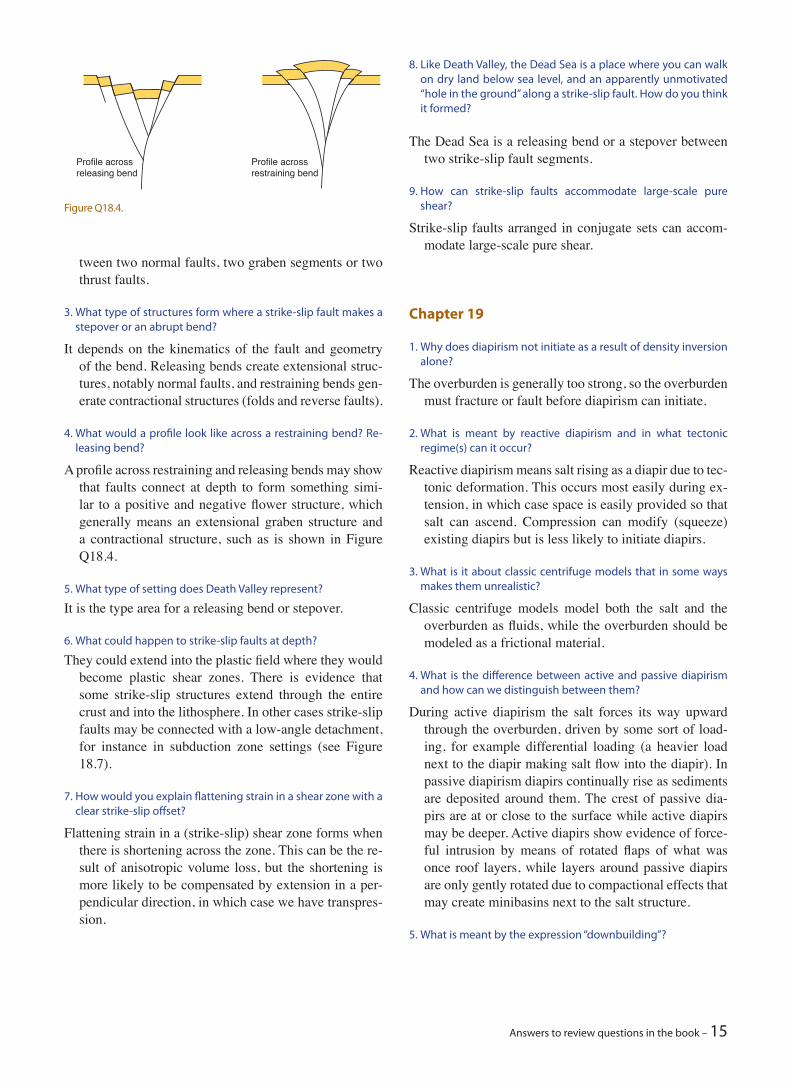
It depends on the kinematics of the fault and geometry of the bend. Releasing bends create extensional struc-tures, notably normal faults, and restraining bends gen-erate contractional structures (folds and reverse faults).
4. What would a profile look like across a restraining bend? Re-leasing bend?
A profile across restraining and releasing bends may show that faults connect at depth to form something simi-lar to a positive and negative flower structure, which generally means an extensional graben structure and a contractional structure, such as is shown in Figure Q18.4.
5. What type of setting does Death Valley represent?
It is the type area for a releasing bend or stepover.
6. What could happen to strike-slip faults at depth?
They could extend into the plastic field where they would become plastic shear zones. There is evidence that some strike-slip structures extend through the entire crust and into the lithosphere. In other cases strike-slip faults may be connected with a low-angle detachment, for instance in subduction zone settings (see Figure 18.7).
7. How would you explain flattening strain in a shear zone with a clear strike-slip offset?
Flattening strain in a (strike-slip) shear zone forms when there is shortening across the zone. This can be the re-sult of anisotropic volume loss, but the shortening is more likely to be compensated by extension in a per-pendicular direction, in which case we have transpres-sion.
Profile across releasing bend
Profile across restraining bend
Figure Q18.4.
16 – Structural geology
2 looks tight, but remember that the vertical scale is in seconds, so to evaluate interlimb angles the interpreta-tion must be depth converted. At present, the section appear to be a bit squashed. Fold 2 is clearly a result of salt withdrawal. The history of salt withdrawal and di-apir growth is reflected in the thickness variations seen in the evaporite section and some of the higher strata. In fact, this syncline and the one in the right-hand part of the section define salt minibasins.
Fold 1 is a more complex inclined fold, with the main axial surface dipping to the left and with some of a box-fold geometry in the hinge zone. This fold is the tightest one and clearly the result of upwarping during the evolution of the adjacent salt diapir.
Folds 3 is a monocline developed atop a rift-related nor-mal fault. Such monoclines may be due to differential compaction (or fault-propagation faulting). In this case it can be related to the down-warping of the evaporite section above.
Fold 4 is a shallower monocline that seem to have formed in a similar way, marking the flank of the minibasin to the left.
Chapter 20
1. What are the two most basic conditions that must be fulfilled for section balancing to make sense?
The strain must be plane strain or at least close to plane strain, and the section must be oriented in the transport direction, i.e. the section must contain the two princi-pal strain axes X and Z.
2. What is the difference between restoration and forward mod-eling?
Restoration departs from the present (deformed) state and seeks to reconstruct the situation prior to deforma-tion. Forward modeling means to start out with what is thought to be the pre-deformational situation, for in-stance undeformed sedimentary strata, and then apply deformation and study the result.
3. What is meant by ductile strain in restoration?
Ductile strain means deformation that preserves continu-ity at the scale of observation, regardless of the actual microscale deformation mechanisms. Examples of ductile strain dealt with during restoration are large-scale drag or rollovers and bending above reactivated faults or salt diapirs.
Downbuilding is the expression sometimes used about sedimentation around passive diapirism, where sedi-mentary layers are being added as the diapir grows. If our reference is the top of the diapir, which is more or less at the surface (sea bottom), a sedimentary se-quence and the source salt layer will build down under the addition of new strata during passive diapirism.
6. Why do we not see diapirs in the upper part of a gravity-driven décollement setting such as shown in Figure 19.24?
There is no or too little loading that can drive diapirism. The load increases down dip due to gravity and the tapering of the sedimentary wedge overlying the salt.
7. What determines whether a salt wall or salt diapir forms?
The strength of the overburden is important. If the strength is reduced by means of a long fault or fracture zone we can get a salt wall. Salt walls are also common where folding is involved (contractional deformation). However, if weak structures are shorter and more ran-domly or evenly distributed in the overburden, diapirs are more common.
8. What is the difference between a salt sheet and a salt canopy?
A salt sheet is a single salt structure that has flowed lat-erally to obtain a width ≥5 times the thickness of the original diapir or its underlying stem. A canopy forms when several (three or more) such sheets grow into a connected sheet-like structure.
9. What is the effect of a basal salt layer in an orogenic wedge?
It lowers the basal friction and therefore creates a lower height – length ratio of the wedge. It also causes the deformation to extend farther into the foreland, pro-moting a very wide zone of thin-skinned tectonics in orogenic wedges.
10. Can you do a rough interpretation of Figure 1.6 and identify the stratigraphic level of the salt, pencil in salt structures and interpret the folds?
This line is full of interesting details that can be studied. The large-scale features are a Cretaceous rift (from the time when Gondwana rifted apart) and early postrift sediments underlying an evaporitic section. The evap-orites are marked in blue, while purer salt of the lower part of this section is uncolored. The salt has mobilized into diapirs, although their vertical extent seems to be confined by the top of the evaporite layer. Salt move-ments has caused most of the folding. Some of the ax-ial traces have been drawn in on Figure Q19.10. Most of them are upright folds and the folds are open. Fold
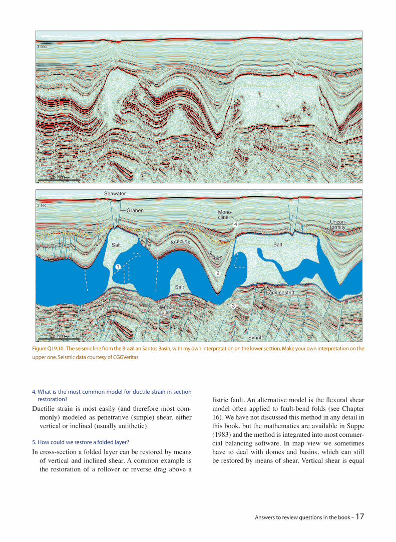
Answers to review questions in the book – 17
4. What is the most common model for ductile strain in section restoration?
Ductilie strain is most easily (and therefore most com-monly) modeled as penetrative (simple) shear, either vertical or inclined (usually antithetic).
5. How could we restore a folded layer?
In cross-section a folded layer can be restored by means of vertical and inclined shear. A common example is the restoration of a rollover or reverse drag above a
listric fault. An alternative model is the flexural shear model often applied to fault-bend folds (see Chapter 16). We have not discussed this method in any detail in this book, but the mathematics are available in Suppe (1983) and the method is integrated into most commer-cial balancing software. In map view we sometimes have to deal with domes and basins, which can still be restored by means of shear. Vertical shear is equal
Figure Q19.10. The seismic line from the Brazilian Santos Basin, with my own interpretation on the lower section. Make your own interpretation on the
upper one. Seismic data courtesy of CGGVeritas.
Salt
SaltSalt
Graben
Seawater
Mono-cline
Salt
Salt
SynriftSynrift
Early postriftEarly postrift
Salt
Graben
Seawater
NormalfaultsNormalfaults
Mono-cline
5 km5 km
4 sec.4 sec.
3 sec.3 sec.
5 sec.5 sec.
5 km
3 sec.
5 sec.
Anticline
Syncline
Anticline
Syncline
Uncon-formityUncon-formity
12
3
4
18 – Structural geology
tonic ones occur enveloped in a later fabric, typically with inclusion trails oblique to the external and later foliation. In other words they occur as porphyroclasts. Syntectonic porpyroblasts grew during deformation. Because porphyroblasts grow outward and because the external foliation tends to rotate with respect to the porphyroblast the inclusion trails commonly become deflected towards the margins of the porphyroblasts. In extreme cases spiral-shaped patterns may occur, particularly in garnets. It may however be difficult to distinguish between syn- and intertectonic porphy-roblasts in cases where intertectonic ones overgrow a crenulated fabric.
4. In what tectonic environment can we expect clockwise P–T paths to form?
A clockwise P–T path implies rapid increase in pressure followed by heating and then decompression. This is difficult to achieve except in subduction settings, where rocks are buried during subduction and later ex-humed.
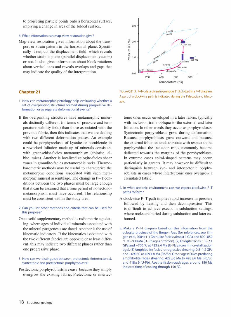
5. Make a P–T-t diagram based on this information from the eclogite province of the Bergen Arcs (for references, see Bin-gen et al, 2004): (1) Granulite facies: almost 1 GPa and 800–850 °C at ~930 Ma (U–Pb ages of zircon). (2) Eclogite facies: 1.8–2.1 GPa and ~700 °C at 423 ± 4 Ma (U-Pb zircon rim crystallization age). (3) Amphibolite facies retrogressive shearing: 0.8–1.2 GPa and ~690 °C at 409 ± 8 Ma (Rb/Sr). Other ages: Dikes predating amphibolite facies shearing: 422 ± 6 Ma to 428 ± 6 Ma (Rb/Sr) and 418 ± 9 (U-Pb). Apatite fission-track ages around 180 Ma indicate time of cooling through 150 °C.
to projecting particle points onto a horizontal surface, implying a change in area of the folded surface.
6. What information can map-view restoration give?
Map-view restoration gives information about the trans-port or strain pattern in the horizontal plane. Specifi-cally it outputs the displacement field, which reveals whether strain is plane (parallel displacement vectors) or not. It also gives information about block rotations about vertical axes and reveals overlaps and gaps that may indicate the quality of the interpretation.
Chapter 21
1. How can metamorphic petrology help evaluating whether a set of overprinting structures formed during progressive de-formation or as separate deformational events?
If the overprinting structures have metamorphic miner-als distinctly different (in terms of pressure and tem-perature stability field) than those associated with the previous fabric, then this indicates that we are dealing with two different deformation phases. An example could be porphyroclasts of kyanite or hornblende in a reworked foliation made up of minerals consistent with greenschist-facies metamorphism (chlorite, al-bite, mica). Another is localized eclogite-facies shear zones in granulite-facies metamorphic rocks. Thermo-barometric methods may be useful to characterize the metamorphic conditions associated with each meta-morphic mineral assemblage. The change in P – T con-ditions between the two phases must be large enough that it can be assumed that a time period of no tectono-metamorphism must have occurred. The relationship must be consistent within the study area.
2. Can you list other methods and criteria that can be used for this purpose?
One useful supplementary method is radiometric age dat-ing, where ages of individual minerals associated with the mineral paragenesis are dated. Another is the use of kinematic indicators. If the kinematics associated with the two different fabrics are opposite or at least differ-ent, this may indicate two different phases rather than one progressive phase.
3. How can we distinguish between pretectonic (intertectonic), syntectonic and posttectonic porphyroblasts?
Posttectonic porphyroblasts are easy, because they simply overgrow the existing fabric. Pretectonic or intertec-
200
3.0
2.0
1.0
0.0400 600 800
CoesiteQuartz
Jadeite + Quartz
Albite
AndalusiteSillimanite
Kyanite
Temperature (°C)
Pres
sure
(GPa
)
~930 Ma409±8 Ma
AFT (~180 Ma)
423±4 Ma
?
Figure Q21.5. P–T–t data given in question 21.5 plotted in a P–T diagram.
A part of a clockwise path is indicated during the Paleozoicand Meso-
zoic.
Answers to review questions in the book – 19
The data and path are shown in the figure. The old (930 Ma) granulite fabric is not directly related to the Cale-donian ages of eclogite and amphibolite facies meta-morphism and must therefore be considered separately (it may or may not be that the rocks were at or close to the surface between the granulite and eclogite facies tectonometamorphic events). A path can be drawn be-tween the 423 ± 4 Ma eclogite-facies event, the 409 ± 8 Ma amphibolite facies event and the AFT date. The latter date indicates burial depths of around 6 km and thus low pressures. The path seems to represent the ret-rograde part of a clockwise P – T path, consistent with a subduction zone setting.
6. What characterizes pre-, syn- and posttectonic sedimentary sequences in a halfgraben setting?
Pretectonic sedimentation in a half-graben is not related to the graben formation. It is expected to show no thickness change across the graben-bounding fault. Syntectonic sediments show thickening towards the graben-bounding fault and rotation so that the layers dip toward the footwall. Unconformities may exist in the high part of the rotated block, while evidence of continuous sedimentation is expected in the lower part (close to the fault). Posttectonic sediments fill in the relief created by the graben without any other evidence of fault movement than that related to differential com-paction across the fault.