Embed Size (px)
Citation preview

H000
GUIDE TO HSK-T TOOLSaSection organizationzOrganized by product series. (Refer to the index on the next page.)
PRODUCT TYPE
TITLE OF PRODUCT SERIESPRODUCT SECTION
indicates the first four letters of the order number, as well as cutting applications.
FIGURE SHOWING THE TOOLING APPLICATION
GEOMETRY
CHIP BREAKER BYCUTTING APPLICATION
uses illustrations and arrows to depict availablemachining applications along with cutting edgelead angles.
LEGEND FORSTOCK STATUS MARK
PRODUCT STANDARDS
REFERENCE PAGEFOR APPLICABLE INSERTS
PAGE REFERENCE
is shown on the left handpage of each double-pagespread.
indicates order numbers,stock status (per right/left hand), applicable inserts, dimensions,and spare parts.
indicates reference pages for detailsof inserts that are applicable to theproduct.
·SPARE PARTS·TECHNICAL DATAindicates reference pages, including the above, on the right hand page of each double-page spread.
aTo Order : Please specify order number and hand of the tool (right/left).
H006
HSK
-T T
OO
LS
H007
HSK
-T T
OO
LS
HSK-T TOOLS
FOR MULTI-TASK MACHINES
95°
95°
95°
95°
Order Number Sto
ck
Insert Number Dimensions
(mm) Mass(lbs)
R L L1 F1 Shim Shim Pin ClampLever
ClampScrew Wrench Punch
H63TH-PCLNR/L-DX12 s sCNMo
CNGo
NP-CNoA43o 65 45 2.9 LLSCN42 LLP14 LLCL14 LLCS108 HKY30R LLH4
Order Number
Sto
ck Insert Number Dimensions
(mm) Mass(lbs)
L1 Shim Shim Pin ClampLever
ClampScrew Plug Wrench
H63TH-PCMNN-H12 s CNMo
CNGo
NP-CNoA43o 100 3.7 LLSCN42 LLP14 LLCL14 LLCS108 HGM-PT1/8 HKY30R
-L12 s 140 6.0 LLSCN42 LLP14 LLCL14 LLCS108 HGM-PT1/8 HKY30R
Order Number
Sto
ck Insert NumberDimensions
(mm) Mass(lbs)
L1 Shim Shim Pin ClampBridge Spring Clamp
Screw Wrench H63TH-DCMNN-H12 s CNMo
CNGo
NP-CNoA43o 100 3.7 LLSCN42 LLP14 DCK2613 DCS1 DC0621T TKY20F
-L12 s 140 6.0 LLSCN42 LLP14 DCK2613 DCS1 DC0621T TKY20F
Order Number Sto
ck
Insert Number Dimensions
(mm) Mass(lbs)
R L L1 F1 Shim Shim Pin ClampBridge Spring Clamp
Screw Wrench Punch
H63TH-DCLNR/L-DX12 s sCNMo
CNGo
NP-CNoA43o 65 45 2.9 LLSCN42 LLP14 DCK2613 DCS1 DC0621T TKY20F LLH4
*
Finish Light MediumFH
(4)
SA
(4)
MA
(4)
Medium Medium Medium ─Semi-HeavyMH
(4)
Standard
(4)
GH
(4)
Stainless CBNMS
(4) (4)
Finish Light MediumFH
(4)
SA
(4)
MA
(4)
Medium Medium Medium ─Semi-HeavyMH
(4)
Standard
(4)
GH
(4)
Stainless CBNMS
(4) (4)
Finish Light Medium FH
(4)
SA
(4)
MA
(4)
Medium Medium Medium ─Semi-Heavy
MH
(4)
Standard
(4)
GH
(4)
Stainless CBNMS
(4) (4)
Finish Light MediumFH
(4)
SA
(4)
MA
(4)
Medium Medium Medium ─Semi-HeavyMH
(4)
Standard
(4)
GH
(4)
Stainless CBN MS
(4) (4)
*
Work Material Hardness Cutting Mode Breaker Grade Cutting Speed (SFM)
PMild Steel <180HB
Finish Cutting FY NX3035 850─1210Light Cutting SY NX3035 770─1100
Medium Cutting MS UE6110 850─1440
Carbon SteelAlloy Steel 180HB─350HB
Finish Cutting FH NX3035 655─935Light Cutting SA UE6110 685─1160
Medium Cutting MA UE6110 620─1065M
Stainless Steel <200HB Finish Cutting FH US735 345─655 Light Cutting SA US735 310─605
Medium Cutting MS US735 275─540K
Gray Cast Iron Tensile Strength<350MPa
Light Cutting MA UC5115 520─965 Medium Cutting Standard UC5115 520─965
Semi-Heavy Cutting Flat Top UC5115 505─915
Work Material Hardness Cutting Mode Breaker Grade Cutting Speed (SFM)
PMild Steel <180HB
Finish Cutting FY NX3035 850─1210 Light Cutting SY NX3035 770─1100
Medium Cutting MS UE6110 850─1440
Carbon SteelAlloy Steel 180HB─350HB
Finish Cutting FH NX3035 655─935Light Cutting SA UE6110 685─1160
Medium Cutting MA UE6110 620─1065M
Stainless Steel <200HB Finish Cutting FH US735 345─655 Light Cutting SA US735 310─605
Medium Cutting MS US735 275─540K
Gray Cast Iron Tensile Strength<350MPa
Light Cutting MA UC5115 520─965Medium Cutting Standard UC5115 520─965
Semi-Heavy Cutting Flat Top UC5115 505─915
*
*
PCLN PCMN
DCLN DCMN
External turning • Facing External turning • Facing
Right hand tool holder shown.
Right hand tool holder shown.
* Clamp Torque (lbf-in) : LLCS108=29 * Clamp Torque (lbf-in) : LLCS108=29
External turning • Facing
External turning • Facing DOUBLE CLAMP type DOUBLE CLAMP type
* Clamp Torque (lbf-in) : DC0621T=44 * Clamp Torque (lbf-in) : DC0621T=44
RECOMMENDED CUTTING CONDITIONS
(Note) Insert photo is an example. Letters show chip breaker style, fi gures show inscribed circle.
s : Inventory maintained in Japan.
RECOMMENDED CUTTING CONDITIONS
SPARE PARTS P001 TECHNICAL DATA Q001
CBN & PCD inserts B022─B024, B054PCLN type inserts A068─A073 DCLN type inserts A068─A073
CBN & PCD inserts B022─B024, B054PCMN type inserts A068─A073 DCMN type inserts A068─A073
H006
HSK
-T T
OO
LS
H007
HSK
-T T
OO
LS
HSK-T TOOLS
FOR MULTI-TASK MACHINES
95°
95°
95°
95°
Order Number Sto
ck
Insert Number Dimensions
(mm) Mass(lbs)
R L L1 F1 Shim Shim Pin ClampLever
ClampScrew Wrench
H63TH-PCLNR/L-DX12 s sCNMo
CNGo
NP-CNoA43o 65 45 2.9 LLSCN42 LLP14 LLCL14 LLCS108 HKY30R
Order Number
Sto
ck Insert Number Dimensions
(mm) Mass(lbs)
L1 Shim Shim Pin ClampLever
ClampScrew Plug Wrench
H63TH-PCMNN-H12 s CNMo
CNGo
NP-CNoA43o 100 3.7 LLSCN42 LLP14 LLCL14 LLCS108 HGM-PT1/8 HKY30R
-L12 s 140 6.0 LLSCN42 LLP14 LLCL14 LLCS108 HGM-PT1/8 HKY30R
Order Number
Sto
ck Insert NumberDimensions
(mm) Mass(lbs)
L1 Shim Shim Pin ClampBridge Spring Clamp
Screw Wrench H63TH-DCMNN-H12 s CNMo
CNGo
NP-CNoA43o 100 3.7 LLSCN42 LLP14 DCK2613 DCS1 DC0621T TKY20F
-L12 s 140 6.0 LLSCN42 LLP14 DCK2613 DCS1 DC0621T TKY20F
Order Number Sto
ck
Insert Number Dimensions
(mm) Mass(lbs)
R L L1 F1 Shim Shim Pin ClampBridge Spring Clamp
Screw Wrench
H63TH-DCLNR/L-DX12 s sCNMo
CNGo
NP-CNoA43o 65 45 2.9 LLSCN42 LLP14 DCK2613 DCS1 DC0621T TKY20F
*
Finish Light MediumFH
(4)
SA
(4)
MA
(4)
Medium Medium Medium ─Semi-HeavyMH
(4)
Standard
(4)
GH
(4)
Stainless CBNMS
(4) (4)
Finish Light MediumFH
(4)
SA
(4)
MA
(4)
Medium Medium Medium ─Semi-HeavyMH
(4)
Standard
(4)
GH
(4)
Stainless CBNMS
(4) (4)
Finish Light Medium FH
(4)
SA
(4)
MA
(4)
Medium Medium Medium ─Semi-Heavy
MH
(4)
Standard
(4)
GH
(4)
Stainless CBNMS
(4) (4)
Finish Light MediumFH
(4)
SA
(4)
MA
(4)
Medium Medium Medium ─Semi-HeavyMH
(4)
Standard
(4)
GH
(4)
Stainless CBN MS
(4) (4)
*
Work Material Hardness Cutting Mode Breaker Grade Cutting Speed (SFM)
PMild Steel <180HB
Finish Cutting FY NX3035 850─1210Light Cutting SY NX3035 770─1100
Medium Cutting MS UE6110 850─1440
Carbon SteelAlloy Steel 180HB─350HB
Finish Cutting FH NX3035 655─935Light Cutting SA UE6110 685─1160
Medium Cutting MA UE6110 620─1065M
Stainless Steel <200HB Finish Cutting FH US735 345─655 Light Cutting SA US735 310─605
Medium Cutting MS US735 275─540K
Gray Cast Iron Tensile Strength<350MPa
Light Cutting MA UC5115 520─965 Medium Cutting Standard UC5115 520─965
Semi-Heavy Cutting Flat Top UC5115 505─915
Work Material Hardness Cutting Mode Breaker Grade Cutting Speed (SFM)
PMild Steel <180HB
Finish Cutting FY NX3035 850─1210 Light Cutting SY NX3035 770─1100
Medium Cutting MS UE6110 850─1440
Carbon SteelAlloy Steel 180HB─350HB
Finish Cutting FH NX3035 655─935Light Cutting SA UE6110 685─1160
Medium Cutting MA UE6110 620─1065M
Stainless Steel <200HB Finish Cutting FH US735 345─655 Light Cutting SA US735 310─605
Medium Cutting MS US735 275─540K
Gray Cast Iron Tensile Strength<350MPa
Light Cutting MA UC5115 520─965Medium Cutting Standard UC5115 520─965
Semi-Heavy Cutting Flat Top UC5115 505─915
*
*
PCLN PCMN
DCLN DCMN
External turning • Facing External turning • Facing
Right hand tool holder shown.
Right hand tool holder shown.
* Clamp Torque (lbf-in) : LLCS108=29 * Clamp Torque (lbf-in) : LLCS108=29
External turning • Facing
External turning • Facing DOUBLE CLAMP type DOUBLE CLAMP type
* Clamp Torque (lbf-in) : DC0621T=44 * Clamp Torque (lbf-in) : DC0621T=44
RECOMMENDED CUTTING CONDITIONS
(Note) Insert photo is an example. Letters show chip breaker style, fi gures show inscribed circle.
s : Inventory maintained in Japan.
RECOMMENDED CUTTING CONDITIONS
SPARE PARTS P001 TECHNICAL DATA Q001
CBN & PCD inserts B022─B024, B054PCLN type inserts A068─A073 DCLN type inserts A068─A073
CBN & PCD inserts B022─B024, B054PCMN type inserts A068─A073 DCMN type inserts A068─A073
H006 H007
95°
95°
95°
95°
WT(lbs)
R L LF WF
H63TH-PCLNR/L-DX12 s sCNMo
CNGo
NP-CNoA43o 65 45 2.9 LLSCN42 LLP14 LLCL14 LLCS108 HKY30R
WT(lbs)
LFH63TH-PCMNN-H12 s CNMo
CNGo
NP-CNoA43o 100 3.7 LLSCN42 LLP14 LLCL14 LLCS108 HGM-PT1/8 HKY30R
H63TH-PCMNN-L12 s 140 6.0 LLSCN42 LLP14 LLCL14 LLCS108 HGM-PT1/8 HKY30R
WT(lbs)
LFH63TH-DCMNN-H12 s CNMo
CNGo
NP-CNoA43o 100 3.7 LLSCN42 LLP14 DCK2613 DCS1 DC0621T TKY20F
H63TH-DCMNN-L12 s 140 6.0 LLSCN42 LLP14 DCK2613 DCS1 DC0621T TKY20F
WT(lbs)
R L LF WF
H63TH-DCLNR/L-DX12 s sCNMo
CNGo
NP-CNoA43o 65 45 2.9 LLSCN42 LLP14 DCK2613 DCS1 DC0621T TKY20F
FH
(4)
LP
(4)
MP
(4)
MK
(4) (4)
RP
(4)
MS
(4) (4)
FH
(4)
LP
(4)
MP
(4)
MK
(4) (4)
RP
(4)
MS
(4) (4)
FH
(4)
LP
(4)
MP
(4)
MK
(4) (4)
RP
(4)
MS
(4) (4)
FH
(4)
LP
(4)
MP
(4)
MK
(4) (4)
RP
(4)
MS
(4) (4)
PCLN PCMN
DCLN DCMN
*2 *2
*2*2
*1 *1
*1*1
LF
LF
LF
LF
WF
WF
HSK
-T T
OO
LS
HSK
-T T
OO
LS
HSK-T TOOLS
FOR MULTI-TASK MACHINESExternal turning • Facing External turning • Facing
Right hand tool holder shown.
Right hand tool holder shown.
*1 Clamp Torque (lbf-in) : LLCS108=29
*2 WT : Mass *1 Clamp Torque (lbf-in) : LLCS108=29
*2 WT : Mass
External turning • Facing
External turning • FacingDOUBLE CLAMP type DOUBLE CLAMP type
*1 Clamp Torque (lbf-in) : DC0621T=44
*2 WT : Mass *1 Clamp Torque (lbf-in) : DC0621T=44
*2 WT : Mass
(Note) Insert photo is an example. Letters show chip breaker style, figures show inscribed circle.
s : Inventory maintained in Japan.
Finish Light Medium
Medium Medium Medium ─RoughStandard
Stainless CBN
Order Number Stoc
k
Insert NumberDimensions
(mm)
Shim Shim Pin ClampLever
ClampScrew Wrench
Light MediumFinish
Medium Medium Medium ─Rough
Stainless CBN
Standard
Order Number Stoc
k
Insert NumberDimensions
(mm)
Shim Shim Pin ClampBridge Spring Clamp
Screw Wrench
Finish Light Medium
Medium Medium Medium ─Rough
Stainless CBN
Standard
Order Number
Stoc
k
Insert NumberDimensions
(mm)
Shim Shim Pin ClampLever
ClampScrew Plug Wrench
Standard
Finish Light Medium
Medium Medium Medium ─Rough
Stainless CBN
Order Number
Stoc
k
Insert NumberDimensions
(mm)
Shim Shim Pin ClampBridge Spring Clamp
Screw Wrench
CUTTING CONDITIONS SEE SECTION ASPARE PARTS M001TECHNICAL DATA N001
PCMN type inserts A096─A102DCMN type inserts A096─A102CBN & PCD inserts B022, B023, B051
CBN & PCD inserts B022, B023, B051CUTTING CONDITIONS SEE SECTION A
PCLN type inserts A096─A102DCLN type inserts A096─A102

H001
H022H020H019H008H021H008H006H007H011H009H010H020H021H019
H014H016H016H017H006H007H009H010H012H012H013H013H022
H100TH-Bpp-ppp
H100TH-EN3232R/L-130H100TH-EV3232R/L-180H63TH-ApppDCLNR/L12H63TH-Bpp-pp
H63TH-DCLNL-L12-3H63TH-DCLNR/L-DX12H63TH-DCMNN-H/L12H63TH-DDJNL-L15-3H63TH-DDJNR/L-DX15H63TH-DDNNN-H/L15H63TH-EN2525R/L-115H63TH-EV2020R/L-105-3H63TH-EV2525R/L-112
H63TH-MGHR/L-DX43pp
H63TH-MMTENR-H/L16H63TH-MMTER-DX16H63TH-MTHR/L-DX43H63TH-PCLNR/L-DX12H63TH-PCMNN-H/L12H63TH-PDJNR/L-DX15H63TH-PDNNN-H/L15H63TH-PRDCN-H/L12H63TH-PRGCR/L-DX12H63TH-SVPBR/L-DX16H63TH-SVVBN-H/L16SL32pp-90
HSK-T TOOLS
*Arranged by Alphabetical order
OUTLINE OF HSK-T TOOLS ..................................................................................... H002CLASSIFICATION OF HSK-T TOOLS ................................................................. H004STANDARD OF HSK-T TOOLS
EXTERNAL TURNING • FACINGCNooINSERTS TOOL HOLDERS ..................................................................................... H006DNooINSERTS TOOL HOLDERS ..................................................................................... H011EXTERNAL TURNING • FACING • BORINGCNooINSERTS TOOL HOLDERS ..................................................................................... H008EXTERNAL TURNING • COPYINGDNooINSERTS TOOL HOLDERS ..................................................................................... H009EXTERNAL TURNING • FACING • COPYINGRCooINSERTS TOOL HOLDERS ..................................................................................... H012FACING • COPYINGVBooINSERTS TOOL HOLDERS ..................................................................................... H013GROOVINGMG INSERTS TOOL HOLDERS .......................................................................................... H014THREADINGMMT INSERTS TOOL HOLDERS ....................................................................................... H016MT INSERTS TOOL HOLDERS ........................................................................................... H017
EXTERNAL TURNING TOOL HOLDERS ................................................... H019BORING BAR HOLDERS ...................................................................................... H021BORING BAR SLEEVES ....................................................................................... H022
H002
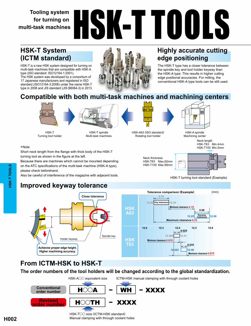
(mm)
12.2 12.3 12.4 12.5 12.6
0.08
12.46
12.4112.385
12.3512.25
0.035
0.025
12.425
12.5812.25
0.10
HSKA63
HSKT63
0.075
0.015
0.33
0.15
HooA XXXXWH− −
HooTH XXXX−
HSK
-T T
OO
LSTooling system
for turning on multi-task machines
HSK-T System (ICTM standard)
Highly accurate cutting edge positioning
HSK-T is a new HSK system designed for turning on multi-task machines that are compatible with HSK-A type (ISO standard: ISO12164-1:2001).The HSK system was developed by a consortium of 17 Japanese manufacturers and registered in ISO standard (ISO12164-3:2008) under the name HSK-T type in 2008 and JIS standard (JIS B6064-3) in 2013.
The HSK-T type has a closer tolerance between the spindle key and tool holder keyway than the HSK-A type. This results in higher cutting edge positional accuracies. For milling, the conventional HSK-A type tools can be still used.
Compatible with both multi-task machines and machining centers
Improved keyway tolerance
HSK-TTurning tool holder
HSK-T spindleMulti-task machines
HSK-A63 (ISO standard)Rotating tool holder
HSK-A spindleMachining center
Close tolerance
Holder keywaySpindle key
Achieves proper edge height.Higher machining accuracy.
Tolerance comparison (Example)
Key tolerance
Minimum clearance
Maximum clearance
Maximum clearance
Minimum clearance
Keywaytolerance
*NoteShort neck length from the flange with thick body of the HSK-T turning tool as shown in the figure at the left.Because there are machines which cannot be mounted depending on the ATC specifications of the multi-task machine (HSK-A type), please check beforehand.Also be careful of interference of the magazine with adjacent tools.
Neck lengthHSK-T63 Min.4mmHSK-T100 Min.5mm
Neck thicknessHSK-T63 Max.62mmHSK-T100 Max.99mm
HSK-T turning tool standard (Example)
HSK-T TOOLS
From ICTM-HSK to HSK-TThe order numbers of the tool holders will be changed according to the global standardization.
HSK-Aoo equivalent size
HSK-Too size (ICTM-HSK standard)Manual clamping with through coolant holes
ICTM-HSK manual clamping with through coolant holes
Conventionalorder number
Revised order number

H003
HSK
-T T
OO
LS
By tilting the machines B spindle (main axis of the tool) at 45 deg. interference between the spindle, holder, workpiece and chuck can be avoided.
Increased stability and accuracy can be achieved because the cutting edge centerline height is not affected by the gap between the spindle and the key.
Straight type tools suitable for use on multi-task machines
New single-action double clamp series
3 on 1 tool for process and tool consolidation
New HSK-T100 size for large workpieces
Highly accurate and rigid HSK-T type tooling system for use on multi-task machines.
Avoid workpiece interference with improved tool accessibility.
The double clamp mechanism offers high rigidity, accuracy, reliability that ensures secure insert clamping. Therefore making it suitable for turning of difficult to machine materials such as stainless and heat resistant alloys.
Improve centerline height by positioning the cutting edge at the center of the spindle.
Work faceNo interference
Drive key Drive keyway
Cle
aran
ce
Handed type forturning and facing
Straight type forturning and facing
For turning,facing and boring
Clamp bridge
Insert
Shim Shim pin
Spring
Clamp screw
3 turning inserts of the same geometry can be installed on a single tool.The same type of insert can be installed for quick change to back up tools.
Different types of inserts can be installed for different applications (rough and semi finishing and finishing)
Inserts in different grade types can be installed to cover various kinds of workpieces.
Larger tool holder sizes for high efficiency machining.Square shank holder type Boring bar / Drill type Sleeve
25x25 size tool7mm plate
A single tool can be used with different sized tool holders.• Available for use with JIS B4126 (ISO 5610) 32x32 and 32x25 tools.• Possible to fit a 25x25 tool by using a 7mm plate. Possible to fit a 1"x1" tool by using a 6.6mm plate.*Please prepare a plate on your own.

H004
95°
117°30´
107°30´
107°30´
95°
95°
93°
95°
117°30´
93°
93°
95°
95°
H63TH-PCLNR/L-DX12
^H006H63TH-DCLNR/L-DX12
^H006H63TH-PDJNR/L-DX15
^H009H63TH-DDJNR/L-DX15
^H009H63TH-SVPBR/L-DX16
^H013H63TH-PRGCR/L-DX12
^H012H63TH-DCLNL-L12-3
^H008H63TH-DDJNL-L15-3
^H011
H63TH-A25KDCLNR/L12H63TH-A32LDCLNR/L12
^H008
H63TH-PCMNN-H/L12
^H007H63TH-DCMNN-H/L12
^H007H63TH-PDNNN-H/L15
^H010H63TH-DDNNN-H/L15
^H010H63TH-SVVBN-H/L16
^H013H63TH-PRDCN-H/L12
^H012
HSK
-T T
OO
LSHSK-T TOOLS
CLASSIFICATION OF HSK-T TOOLSEXTERNAL TURNING • FACING • COPYING
EXTERNAL TURNING • FACING • BORING
Order Number Geometry Order Number Geometry
Order Number Geometry

H005
H63TH-MMTER-DX16
^H016H63TH-MMTENR-H/L16
^H016H63TH-MTHR/L-DX43
^H017
H63TH-Boo-oo
^H021H100TH-Boo-ooo
^H022SL32oo-90
^H022
H63TH-EV2525R/L-112
^H019H100TH-EV3232R/L-180
^H019H63TH-EN2525R/L-115
^H020H100TH-EN3232R/L-130
^H020H63TH-EV2020R/L-105-3
^H021
*1
*1
*2
H63TH-MGHR/L-DX43oo
^H014
HSK
-T T
OO
LS
EXTERNAL TURNING TOOL HOLDERS
THREADING BORING BAR HOLDERS
*1 Mitsubishi Materials is licensed for production and distribution of these tools from MORI SEIKI Co., LTD. under Japan Patent No.3720202.
*2 The SL32oo-90 sleeve is only for use with H100TH-B32-135.
Order Number Holder
Order Number Geometry Order Number Holder
(Sleeve)
Order Number Geometry
GROOVING

H006
95°
95°
WT(lbs)
R L LF WF
H63TH-PCLNR/L-DX12 s sCNMo
CNGo
NP-CNoA43o 65 45 2.9 LLSCN42 LLP14 LLCL14 LLCS108 HKY30R
WT(lbs)
R L LF WF
H63TH-DCLNR/L-DX12 s sCNMo
CNGo
NP-CNoA43o 65 45 2.9 LLSCN42 LLP14 DCK2613 DCS1 DC0621T TKY20F
FH
(4)
LP
(4)
MP
(4)
MK
(4) (4)
RP
(4)
MS
(4) (4)
FH
(4)
LP
(4)
MP
(4)
MK
(4) (4)
RP
(4)
MS
(4) (4)
PCLN
DCLN
*2
*2
*1
*1
LF
LF
WF
WF
HSK
-T T
OO
LSHSK-T TOOLS
FOR MULTI-TASK MACHINESExternal turning • Facing
Right hand tool holder shown.
Right hand tool holder shown.
*1 Clamp Torque (lbf-in) : LLCS108=29
*2 WT : Mass
External turning • Facing DOUBLE CLAMP type
*1 Clamp Torque (lbf-in) : DC0621T=44
*2 WT : Mass
(Note) Insert photo is an example. Letters show chip breaker style, figures show inscribed circle.
s : Inventory maintained in Japan.
Finish Light Medium
Medium Medium Medium ─RoughStandard
Stainless CBN
Order Number Sto
ck
Insert NumberDimensions
(mm)
Shim Shim Pin ClampLever
ClampScrew Wrench
Light MediumFinish
Medium Medium Medium ─Rough
Stainless CBN
Standard
Order Number Sto
ck
Insert NumberDimensions
(mm)
Shim Shim Pin ClampBridge Spring Clamp
Screw Wrench
CBN & PCD inserts B022, B023, B051CUTTING CONDITIONS SEE SECTION A
PCLN type inserts A096─A102DCLN type inserts A096─A102

H007
95°
95°
WT(lbs)
LFH63TH-PCMNN-H12 s CNMo
CNGo
NP-CNoA43o 100 3.7 LLSCN42 LLP14 LLCL14 LLCS108 HGM-PT1/8 HKY30R
H63TH-PCMNN-L12 s 140 6.0 LLSCN42 LLP14 LLCL14 LLCS108 HGM-PT1/8 HKY30R
WT(lbs)
LFH63TH-DCMNN-H12 s CNMo
CNGo
NP-CNoA43o 100 3.7 LLSCN42 LLP14 DCK2613 DCS1 DC0621T TKY20F
H63TH-DCMNN-L12 s 140 6.0 LLSCN42 LLP14 DCK2613 DCS1 DC0621T TKY20F
FH
(4)
LP
(4)
MP
(4)
MK
(4) (4)
RP
(4)
MS
(4) (4)
FH
(4)
LP
(4)
MP
(4)
MK
(4) (4)
RP
(4)
MS
(4) (4)
PCMN
DCMN
*2
*2
*1
*1
LF
LF
HSK
-T T
OO
LS
External turning • Facing
*1 Clamp Torque (lbf-in) : LLCS108=29
*2 WT : Mass
External turning • Facing DOUBLE CLAMP type
*1 Clamp Torque (lbf-in) : DC0621T=44
*2 WT : Mass
Finish Light Medium
Medium Medium Medium ─Rough
Stainless CBN
Standard
Order Number
Sto
ck Insert NumberDimensions
(mm)
Shim Shim Pin ClampLever
ClampScrew Plug Wrench
Standard
Finish Light Medium
Medium Medium Medium ─Rough
Stainless CBN
Order Number
Sto
ck Insert NumberDimensions
(mm)
Shim Shim Pin ClampBridge Spring Clamp
Screw Wrench
CUTTING CONDITIONS SEE SECTION ASPARE PARTS M001TECHNICAL DATA N001
PCMN type inserts A096─A102DCMN type inserts A096─A102CBN & PCD inserts B022, B023, B051
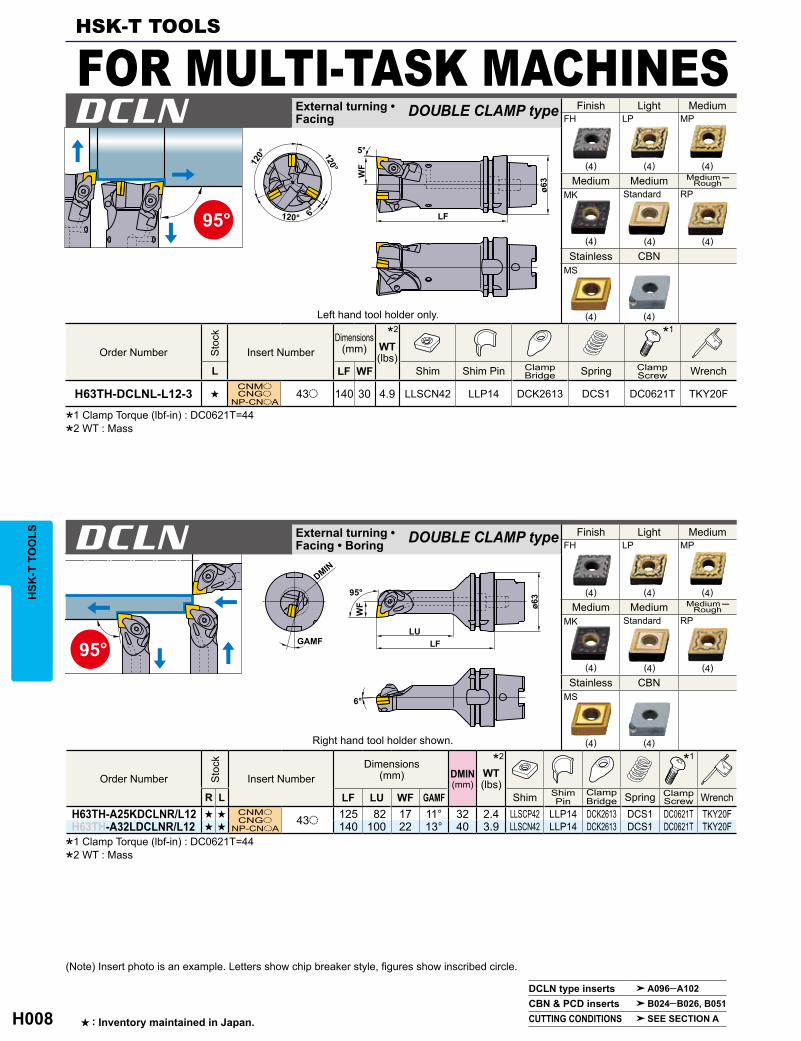
H008
95°
FH
(4)
LP
(4)
MP
(4)
MK
(4) (4)
RP
(4)
MS
(4) (4)
95°
WT(lbs)
L LF WF
H63TH-DCLNL-L12-3 sCNMoCNGo
NP-CNoA43o 140 30 4.9 LLSCN42 LLP14 DCK2613 DCS1 DC0621T TKY20F
DMIN(mm)
WT(lbs)
R L LF LU WF GAMFH63TH-A25KDCLNR/L12 s s CNMo
CNGo
NP-CNoA43o 125 82 17 11° 32 2.4 LLSCP42 LLP14 DCK2613 DCS1 DC0621T TKY20F
H63TH-A32LDCLNR/L12 s s 140 100 22 13° 40 3.9 LLSCN42 LLP14 DCK2613 DCS1 DC0621T TKY20F
FH
(4)
LP
(4)
MP
(4)
MK
(4) (4)
RP
(4)
MS
(4) (4)
DCLN
DCLN
*2 *1
*2 *1
LF
WF
WF
GAMFLU
LF
DMIN
HSK
-T T
OO
LSHSK-T TOOLS
FOR MULTI-TASK MACHINESExternal turning • Facing
External turning • Facing • Boring
DOUBLE CLAMP type
DOUBLE CLAMP type
Left hand tool holder only.
Right hand tool holder shown.
*1 Clamp Torque (lbf-in) : DC0621T=44
*2 WT : Mass
*1 Clamp Torque (lbf-in) : DC0621T=44
*2 WT : Mass
s : Inventory maintained in Japan.
DCLN type inserts A096─A102CBN & PCD inserts B024─B026, B051CUTTING CONDITIONS SEE SECTION A
Standard
Finish Light Medium
Medium Medium Medium ─Rough
Stainless CBN
Order Number Sto
ck
Insert NumberDimensions
(mm)
Shim Shim Pin ClampBridge Spring Clamp
Screw Wrench
Finish Light Medium
Medium Medium Medium ─Rough
Stainless CBN
Order Number Sto
ck
Insert NumberDimensions
(mm)
Shim ShimPin
ClampBridge Spring Clamp
Screw Wrench
Standard
(Note) Insert photo is an example. Letters show chip breaker style, figures show inscribed circle.

H009
93°
93°
WT(lbs)
R L LF WF
H63TH-PDJNR/L-DX15 s sDNMoDNGo
NP-DNoA 43o 65 45 2.6 LLSDN43(LLSDN42) LLP14 LLCL24 LLCS108 HKY30R
FH
(4)
LP
(4)
MP
(4)
MK
(4)
RP
(4)
MS
(4)
R/L
(4) (4)
*1*2*3
WT(lbs)
R L LF WF
H63TH-DDJNR/L-DX15 s sDNMoDNGo
NP-DNoA 43o 65 45 2.6 LLSDN43(LLSDN42) LLP24 DCK2613 DCS1 DC0621T TKY20F
FH
(4)
LP
(4)
MP
(4)
MK
(4)
RP
(4)
MS
(4)
R/L
(4) (4)
*2*3 *1
DDJN
PDJN
LF
LF
WF
WF
HSK
-T T
OO
LSExternal turning • Copying DOUBLE CLAMP type
External turning • Copying
Right hand tool holder shown.
Right hand tool holder shown.
*1 Clamp Torque (lbf-in) : LLCS108=29
*2 Please use shim no. LLSDN42 with .25inch thick inserts. When using .25inch thick inserts, the shim should be ordered separately.
*3 WT : Mass
*1 Clamp Torque (lbf-in) : DC0621T=44
*2 Please use shim no. LLSDN42 with .25inch thick inserts. When using .25inch thick inserts, the shim should be ordered separately.
*3 WT : Mass
PDJN type inserts A103─A109DDJN type inserts A103─A109CBN & PCD inserts B024─B026, B051
Finish Light Medium
Medium Medium ─Rough Stainless
G Class CBN
Finish Light Medium
Medium Medium ─Rough Stainless
G Class CBN
Order Number Sto
ck
Insert NumberDimensions
(mm)
Shim Shim Pin Clamp Lever Clamp Screw Wrench
Order Number Sto
ck
Insert NumberDimensions
(mm)
Shim Shim Pin ClampBridge Spring Clamp
Screw Wrench
CUTTING CONDITIONS SEE SECTION ASPARE PARTS M001TECHNICAL DATA N001

H010
107°30´
FH
(4)
LP
(4)
MP
(4)
MK
(4)
RP
(4)
MS
(4)
R/L
(4) (4)
107°30´
FH
(4)
LP
(4)
MP
(4)
MK
(4)
RP
(4)
MS
(4)
R/L
(4) (4)
WT(lbs)
LFH63TH-PDNNN-H15 s DNMo
DNGo
NP-DNoA43o 100 3.5 LLSDN43
(LLSDN42) LLP14 LLCL24 LLCS108 HGM-PT1/8 HKY30RH63TH-PDNNN-L15 s 140 5.5 LLSDN43
(LLSDN42) LLP14 LLCL24 LLCS108 HGM-PT1/8 HKY30R
WT(lbs)
LFH63TH-DDNNN-H15 s DNMo
DNGo
NP-DNoA43o 100 3.5 LLSDN43
(LLSDN42) LLP24 DCK2613 DCS1 DC0621T TKY20FH63TH-DDNNN-L15 s 140 5.5 LLSDN43
(LLSDN42) LLP24 DCK2613 DCS1 DC0621T TKY20F
*1
*2*3
*2*3
*1
PDNN
DDNN
LF
LF
HSK
-T T
OO
LS
External turning • Copying
External turning • Copying DOUBLE CLAMP type
*1 Clamp Torque (lbf-in) : LLCS108=29
*2 Please use shim no. LLSDN42 with .25inch thick inserts. When using .25inch thick inserts, the shim should be ordered separately.
*3 WT : Mass
*1 Clamp Torque (lbf-in) : DC0621T=44
*2 Please use shim no. LLSDN42 with .25inch thick inserts. When using .25inch thick inserts, the shim should be ordered separately.
*3 WT : Mass
(Note) Insert photo is an example. Letters show chip breaker style, figures show inscribed circle.
s : Inventory maintained in Japan.
PDNN type inserts A103─A109DDNN type inserts A103─A109CBN & PCD inserts B024─B026, B051CUTTING CONDITIONS SEE SECTION A
HSK-T TOOLS
FOR MULTI-TASK MACHINESFinish Light Medium
Medium Stainless
G Class CBN
Order Number
Sto
ck Dimensions(mm)
Shim Shim Pin ClampLever
ClampScrew Plug Wrench
Finish Light Medium
Medium Stainless
G Class CBN
Order Number
Sto
ck
Dimensions(mm)
Shim Shim Pin ClampBridge Spring Clamp
Screw Wrench
Medium ─Rough
Insert Number
Medium ─Rough
Insert Number

H011
93°
FH
(4)
LP
(4)
MP
(4)
MK
(4)
RP
(4)
MS
(4)
WT(lbs)
L LF WF
H63TH-DDJNL-L15-3 s
DNMo
DNGo
NP-DNoA43o 140 30 4.9 LLSDN43
(LLSDN42) LLP24 DCK2613 DCS1 DC0621T TKY20F
*2*3 *1
DDJN
LF
WF
HSK
-T T
OO
LS
External turning • Facing
*1 Clamp Torque (lbf-in) : DC0621T=44
*2 Please use shim no. LLSDN42 with .25inch thick inserts. When using .25inch thick inserts, the shim should be ordered separately.
*3 WT : Mass
DOUBLE CLAMP type
Left hand tool holder only.
DDJN type inserts A103─A109CBN & PCD inserts B024─B026, B051
Finish Light
Medium Medium
Medium ─Rough Stainless
Order Number Sto
ck
Insert NumberDimensions
(mm)
Shim Shim Pin ClampBridge Spring Clamp
Screw Wrench
CUTTING CONDITIONS SEE SECTION ASPARE PARTS M001TECHNICAL DATA N001

H012
(12)
(12)
WT(lbs)
R L LF WF
H63TH-PRGCR/L-DX12 s s RCMX 1204M0 65 45 2.6 LLSRN123 LLP13 LLCL112 LLCS106 HKY25R
WT(lbs)
LF B2
H63TH-PRDCN-H12 s
RCMX 1204M0100 69° 3.1 LLSRN123 LLP13 LLCL112 LLCS106 HGM-PT1/8 HKY25R
H63TH-PRDCN-L12 s 140 75° 5.1 LLSRN123 LLP13 LLCL112 LLCS106 HGM-PT1/8 HKY25R
P <180HB UE6110 670─1150180HB─350HB UE6110 490─850
M <200HB US735 230─425
PRGC
PRDC
*2
*2
*1
*1
LF
WF
LF
HSK
-T T
OO
LSHSK-T TOOLS
FOR MULTI-TASK MACHINESExternal turning • Facing • Copying
External turning • Facing • Copying
Right hand tool holder shown.
RECOMMENDED CUTTING CONDITIONS
(Note) Insert photo is an example. Letters show chip breaker style, figures show inscribed circle.
s : Inventory maintained in Japan.
PRGC type inserts A151PRDC type inserts A151
Medium
Order Number Sto
ck
Insert NumberDimensions
(mm)
Shim Shim Pin Clamp Lever Clamp Screw Wrench
Medium
Order Number
Sto
ck
Insert NumberDimensions
(mm)
Shim Shim Pin ClampLever
ClampScrew Plug Wrench
Work Material Hardness Cutting Mode Breaker Grade Cutting Speed (SFM)
Mild SteelCarbon Steel • Alloy Steel
Stainless Steel
Medium CuttingMedium CuttingMedium Cutting
StandardStandardStandard
*1 Clamp Torque (lbf-in) : LLCS106=19
*2 WT : Mass
*1 Clamp Torque (lbf-in) : LLCS106=19
*2 WT : Mass
SPARE PARTS M001

H013
117°30´
117°30´
R/L-F
(3)
SV
(3)
MV
(3)
MP
(3)
MM
(3) (3)
R/L-F
(3)
SV
(3)
MV
(3)
MP
(3)
MM
(3) (3)
WT(lbs)
R L LF WF
H63TH-SVPBR/L-DX16 s sVBMTVBGT 33o 65 45 2.4 SPSVN32 BCP141 TS35D TKY15F
WT(lbs)
LF B2
H63TH-SVVBN-H16 s VBMTVBGT 33o
100 66°30' 2.9 SPSVN32 BCP141 TS35D HGM-PT1/8 TKY15F
H63TH-SVVBN-L16 s 140 72°30' 4.9 SPSVN32 BCP141 TS35D HGM-PT1/8 TKY15F
P<180HB
F AP25N 820 (490─985)MV UE6020 655 (490─820)
180HB─350HBF AP25N 690 (490─850)
MV UE6020 555 (390─690)
M <200HB MM MC7025 500 (280─705)
K MV UE6020 555 (460─655)
SVPB
SVVB
*2
*2
*1
*1
LF
WF
LF
B2
B2
HSK
-T T
OO
LS
Facing • Copying
Right hand tool holder shown.
RECOMMENDED CUTTING CONDITIONS
SPARE PARTS M001TECHNICAL DATA N001
SVPB type inserts A162─A164SVVB type inserts A162─A164CBN inserts B044
Finish Light
Medium Medium
Work Material Hardness Cutting Mode Breaker Grade Cutting Speed (SFM)
Mild Steel
Carbon SteelAlloy Steel
Stainless SteelGray Cast Iron Tensile Strength <350MPa Medium Cutting
Medium CuttingMedium CuttingFinish Cutting
Medium CuttingFinish Cutting
Finish Light
Medium Medium
CBN
Order Number Insert NumberDimensions
(mm)
Shim Shim Pin Clamp Screw Wrench
Finish Light
Medium Medium
Stainless CBN
Order Number Insert NumberDimensions
(mm)
Shim Shim Pin Clamp Screw Plug Wrench
Sto
ckS
tock
Facing • Copying
Stainless
*1 Clamp Torque (lbf-in) : TS35D=31
*2 WT : Mass
*1 Clamp Torque (lbf-in) : TS35D=31
*2 WT : Mass

H014
WT(lbs)
R L CW CDX LF WF
H63TH-MGHR/L-DX4315 s s
MGTR/L43125
│
43470
1.25 1.2
65 45 2.6 MTK1R/L HBH06020 MES3 HKY40R
1.45 1.5
1.5<CW<2.3 3
H63TH-MGHR/L-DX4323 s s 2.3<CW<3.3 4.5
H63TH-MGHR/L-DX4333 s s 3.3<CW<4.7 4.5
P180─350HB
VP20MF 390 (330─460) .0039 (.0012─.0071)
NX2525 425 (330─525) .0047 (.0012─.0079)
M <200HB VP20MF 390 (330─460) .0039 (.0012─.0071)
K VP20MF 390 (330─460) .0039 (.0012─.0071)
MG
*2 *1
LFCW
WF
CDX
HSK
-T T
OO
LSHSK-T TOOLS
FOR MULTI-TASK MACHINESGrooving
Right hand tool holder shown.
s : Inventory maintained in Japan. (10 inserts in one case) (1 insert in one case for CBN)
RECOMMENDED CUTTING CONDITIONS
Order Number Insert NumberDimensions (mm)
ClampBridge
ClampScrew Spring
Sto
ck
Wrench
Work Material Hardness Grade Cutting Speed (SFM) Feed (IPR)
Carbon SteelAlloy Steel
Stainless Steel
Gray Cast Iron Tensile Strength <350MPa
*1 Clamp Torque (lbf-in) : HBH06020=62
*2 WT : Mass

H015
CW PDPT IC S RE
VP20
MF
NX25
25
UTi2
0T
MB8
025
R L R L R L RMGTR/L43125 s s s s s s s 1.25 1.2 12.7 4.76 0.2 MGTR/L...
MGTR/L43145 s s s s s 1.45 1.5 12.7 4.76 0.2
MGTR/L43150 s s s s s s s 1.5 3 12.7 4.76 0.2
MGTR/L43175 s s s s s s 1.75 3 12.7 4.76 0.2
MGTR/L43200 s s s s s s s 2 3 12.7 4.76 0.2
MGTR/L43230 s s s s s s 2.3 3 12.7 4.76 0.2
MGTR/L43250 s s s s s s s 2.5 4.5 12.7 4.76 0.3
MGTR/L43260 s s s s s 2.6 4.5 12.7 4.76 0.3
MGTR/L43270 s s s s 2.7 4.5 12.7 4.76 0.3
MGTR/L43280 s s s s 2.8 4.5 12.7 4.76 0.3
MGTR/L43300 s s s s s s s 3 4.5 12.7 4.76 0.3
MGTR/L43320 s s s 3.2 4.5 12.7 4.76 0.3
MGTR/L43330 s s s s 3.3 4.5 12.7 4.76 0.3
MGTR/L43350 s s s s s s s 3.5 4.5 12.7 4.76 0.3
MGTR/L43400 s s s s s s 4 4.5 12.7 4.76 0.3
MGTR/L43420 s s s s s 4.2 4.5 12.7 4.76 0.4
MGTR/L43430 s s s s s 4.3 4.5 12.7 4.76 0.4
MGTR/L43450 s s s s s s 4.5 4.5 12.7 4.76 0.4
MGTR/L43470 s s s s s s 4.7 4.5 12.7 4.76 0.4
PDPTRE
IC
CW
PDPTRE
IC
CW
HSK
-T T
OO
LS
CBN Insert
Right hand insert shown.
SPARE PARTS M001TECHNICAL DATA N001
Stock
Order Number
CoatedDimensions (mm)
Cermet Carbide CBNGeometry
(mm)
INSERTS FOR MG TYPE

H016
WT(lbs)
R LF WF
H63TH-MMTER-DX16 s MMT16ER ooooo 65 45 2.6 SETK51 SETS51 CR4 CTE32TP15 HFC03008 zTKY15FxHKY20R
WT(lbs)
LF
H63TH-MMTENR-H16 s
MMT16ER ooooo
100 3.7 SETK51 SETS51 CR4 CTE32TP15 HFC03008 HGM-PT1/8 zTKY15FxHKY20R
H63TH-MMTENR-L16 s 140 6.0 SETK51 SETS51 CR4 CTE32TP15 HFC03008 HGM-PT1/8 zTKY15FxHKY20R
*2*2*3
P <180HB VP10MF 490 (230─755)VP15TF 330 (195─460)
180─350HB VP10MF 460 (260─655)VP15TF 330 (195─460)
M <200HB VP10MF 425 (260─590)VP15TF 260 (130─390)
K VP10MF 460 (260─655)VP15TF 295 (195─390)
MMTE
MMTEN
*2 *1 *1
WF
LF
LF
HSK
-T T
OO
LSHSK-T TOOLS
FOR MULTI-TASK MACHINESThreading
Threading
*1 For use with B axis tilted at 45 degrees.
*2 Clamp Torque (lbf-in) : SETS51=31, HFC03008=13
*3 WT : Mass
s : Inventory maintained in Japan.(5 inserts in one case)
RECOMMENDED CUTTING CONDITIONS
*1
Right hand tool holder only.
Tool holder for right hand insert only.
MMT type inserts G014, G016, G018, G020
Order Number Sto
ck
Insert NumberDimensions
(mm)
ClampBridge
ClampScrew Stop Ring Shim Shim
Screw Wrench
Order Number
Sto
ck Insert NumberDimensions
(mm)
ClampScrew Stop Ring Shim Shim
Screw Plug WrenchClampBridge
Gray Cast Iron
Mild Steel
Stainless Steel
Work Material
Tensile Strength <350MPa
Carbon SteelAlloy Steel
Hardness Grade Cutting Speed (SFM)
*1 Clamp Torque (lbf-in) : SETS51=31, HFC03008=13
*2 WT : Mass
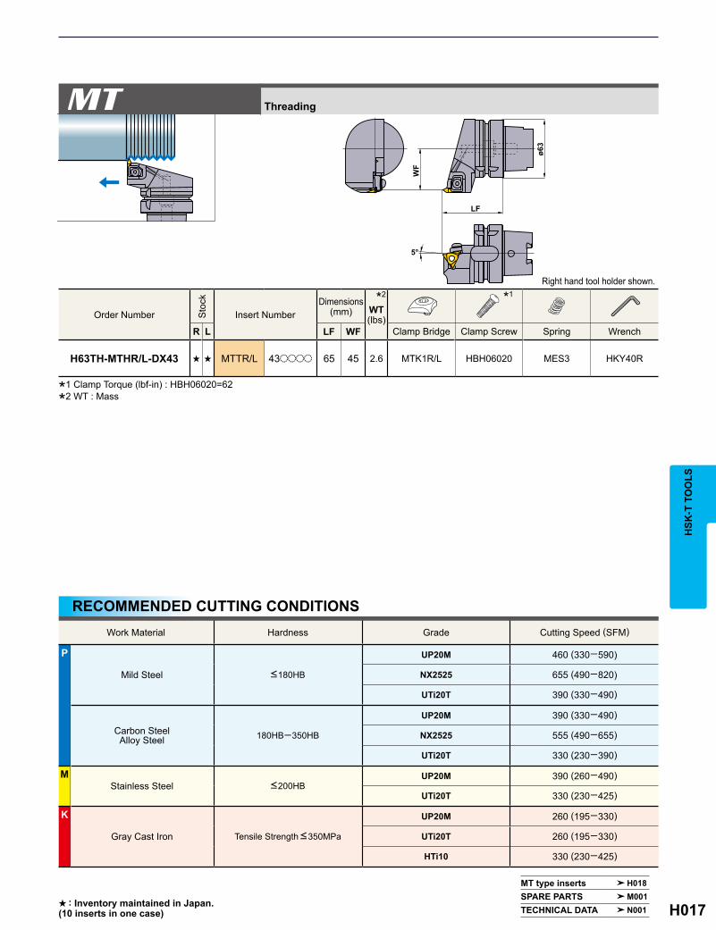
H017
WT(lbs)
R L LF WF
H63TH-MTHR/L-DX43 s s MTTR/L 43oooo 65 45 2.6 MTK1R/L HBH06020 MES3 HKY40R
*1
P
<180HB
UP20M 460 (330─590)
NX2525 655 (490─820)
UTi20T 390 (330─490)
180HB─350HB
UP20M 390 (330─490)
NX2525 555 (490─655)
UTi20T 330 (230─390)
M<200HB
UP20M 390 (260─490)
UTi20T 330 (230─425)
K UP20M 260 (195─330)
UTi20T 260 (195─330)
HTi10 330 (230─425)
MT
*2
WF
LF
HSK
-T T
OO
LS
Threading
Right hand tool holder shown.
RECOMMENDED CUTTING CONDITIONS
MT type inserts H018SPARE PARTS M001TECHNICAL DATA N001
Order Number Insert NumberDimensions
(mm)
Clamp Bridge Clamp Screw Spring Wrench
Sto
ck
Work Material Hardness Grade Cutting Speed (SFM)
Gray Cast Iron
Mild Steel
Stainless Steel
Carbon SteelAlloy Steel
Tensile Strength <350MPa
*1 Clamp Torque (lbf-in) : HBH06020=62
*2 WT : Mass
s : Inventory maintained in Japan.(10 inserts in one case)

H018
UP2
0M
NX25
25
UTi
20T
HTi
10 IC S RE
MTTR436000 G s s ─ 0.8 12.7 4.76 0MTTR436001 G s s s s 1.0 ─ 1.75 12.7 4.76 0.1MTTL436001 G s s s 1.0 ─ 1.75 12.7 4.76 0.1MTTR436002 G s s s s 2.0 ─ 2.5 12.7 4.76 0.2MTTL436002 G s s 2.0 ─ 2.5 12.7 4.76 0.2MTTR436003 G s s s s 3.0 ─ 3.5 12.7 4.76 0.3MTTL436003 G s s 3.0 ─ 3.5 12.7 4.76 0.3MTTR436004 G s s 4.0 ─ 4.5 12.7 4.76 0.4MTTR435501 G s s 28 ─ 10 12.7 4.76 0.1MTTR435502 G s s 16 ─ 8 12.7 4.76 0.2MTTR435503 G s s 11 ─ 8 12.7 4.76 0.3
0.75 1.00 1.25 1.50 1.75 2.00 2.50 3.00 3.50 4.00 4.50h1 0.46 0.61 0.77 0.92 1.07 1.23 1.53 1.84 2.15 2.45 2.76h2 0.35 0.47 0.59 0.70 0.82 0.94 1.17 1.41 1.65 1.87 2.11
0.11 0.14 0.18 0.22 0.25 0.29 0.36 0.43 0.50 0.58 0.651 0.18 0.20 0.20 0.25 0.25 0.25 0.30 0.30 0.35 0.35 0.402 0.13 0.15 0.18 0.20 0.20 0.25 0.25 0.25 0.30 0.30 0.353 0.10 0.10 0.12 0.15 0.20 0.20 0.20 0.25 0.25 0.25 0.304 0.05 0.10 0.12 0.15 0.15 0.15 0.20 0.20 0.20 0.25 0.255 0.06 0.10 0.10 0.12 0.15 0.15 0.20 0.20 0.25 0.256 0.05 0.07 0.10 0.10 0.10 0.15 0.20 0.20 0.207 0.05 0.08 0.10 0.15 0.15 0.20 0.208 0.05 0.10 0.10 0.15 0.15 0.159 0.08 0.10 0.10 0.15 0.15
10 0.05 0.09 0.10 0.10 0.1511 0.05 0.10 0.10 0.1012 0.05 0.10 0.1013 0.05 0.1014 0.06
y a
SIC
RE
SIC
RE
HSK
-T T
OO
LSHSK-T TOOLS
FOR MULTI-TASK MACHINESINSERTS FOR MT TYPE
MTTR/L(60°)
MTTR(55°)
Right hand insert shown.
The chart on the right shows the cuttingdepths when machining external ISO metric screw threads.When using cermet grades or cutting stainless steel, please increase the number of passes by 2 or 3 extra passes.
(Note) The first pass causes a high load on the cutting edge. In order to avoid damage, keep the depth of cut to 0.4 ─ 0.5mm maximum.
STANDARD OF DEPTH OF CUT Metric Screw Thread
a
a
Right hand insert shown.
Unit : mm
Partial profile
Partial profile
s : Inventory maintained in Japan.(10 inserts in one case)
Type
Part
ial P
rofil
e 60
°Pa
rtia
l Pro
file
55°
Order Number
Cla
ss
Coated Cermet CarbidePitch
mm thread/inch
Dimensions (mm)
Geometry
P (Pitch)
r (Corner Radius)
Num
ber o
f Pas
ses

H019
WT(lbs)
R L LF LB LSCX H h1 h2 WF S6 b1 b2
H63TH-EV2525R/L-112 s s 150 112 77 25 32 53 45 13 38 32 8.6 HSS12025 HGM-PT1/8
WT(lbs)
R L LF LB LSCX H h1 h2 WF S6 b1 b2
H100TH-EV3232R/L-180 s s 220 180 130 32 40 68 57 17 46 43 25.8 HSS14035 HSS06006
*
*
WF
LBW
F
S6
LB
LSCX
LF
S6
LSCX
LF
HSK
-T T
OO
LS
EXTERNAL TURNING TOOL HOLDERS External turning • Facing
Right hand tool holder shown.
(Note) Possible to fit a 25 x 25 tool by using a 7mm plate. Possible to fit a 1" x 1" tool by using a 6.6mm plate.
EXTERNAL TURNING TOOL HOLDERS External turning • Facing
This holder is for 25×25 size tools. Please shorten the tool as shown below before use.
This holder is for 32×32 and 32 x 25 size tools.
Right hand tool holder shown.
Cut
y
y
SPARE PARTS M001TECHNICAL DATA N001
Order NumberStock Dimensions (mm)
Clamp Screw Plug
Order NumberStock Dimensions (mm)
Clamp Screw Plug
* WT : Mass
* WT : Mass

H020
WT(lbs)
R L LB LU LF H h1 h2 b1 b2
H63TH-EN2525R/L-115 s s 115 40 110 25 32 53 45 45 8.2 HSS12030 HSS06006
WT(lbs)
R L LB LU LF H h1 h2 b1 b2
H100TH-EN3232R/L-130 s s 130 40 110 32 32 68 47 43 14.6 HSS14030 HSS06006
*
*
LB
LB
LF
LU
LF
LU
HSK
-T T
OO
LSHSK-T TOOLS
FOR MULTI-TASK MACHINES
EXTERNAL TURNING TOOL HOLDERS External turning • Facing
Right hand tool holder shown.
Cut
(Note) Possible to fit a 25 x 25 tool by using a 7mm plate. Possible to fit a 1" x 1" tool by using a 6.6mm plate.
EXTERNAL TURNING TOOL HOLDERS External turning • Facing
This holder is for 25×25 size tools. Please shorten the tool as shown below before use.
This holder is for 32×32 and 32 x 25 size tools. Please shorten the tool as shown below before use.
Mitsubishi Materials is licensed for production and distribution of these tools from MORI SEIKI Co., LTD. under Japan Patent No.3720202.
Mitsubishi Materials is licensed for production and distribution of these tools from MORI SEIKI Co., LTD. under Japan Patent No.3720202.
Right hand tool holder shown.
Cut
y
y
s : Inventory maintained in Japan.
Order NumberStock Dimensions (mm)
Clamp Screw Plug
Order NumberStock Dimensions (mm)
Clamp Screw Plug
* WT : Mass
* WT : Mass

H021
WT(lbs)
R L LF LB LSCX H BD WF S6 b1
H63TH-EV2020R/L-105-3 s s 140 105 70 20 90 40 15 35 6.4 HSS12030 HSS05012 HSS06006
WT(lbs)
BD DCB LF CBDP M
H63TH-B08-65 s 28 8 65 40 M8 2.0 HSS08010
H63TH-B10-70 s 35 10 70 45 M8 2.2 HSS08012
H63TH-B12-70 s 42 12 70 45 M8 2.4 HSS08012
H63TH-B16-75 s 48 16 75 50 M10 2.9 HSS10016
H63TH-B20-75 s 52 20 75 50 M10 3.1 HSS10016
H63TH-B25-83 s 62 25 83 58 M12 3.7 HSS12016
H63TH-B32-87 s 62 32 87 62 M12 3.7 HSS12016
H63TH-B40-97 s 65 40 97 72 M16 4.0 HSS16012
*
*
LBBD
S6
WF
LF
LSCX
LF
CBDP
DC
BB
D
HSK
-T T
OO
LS
EXTERNAL TURNING TOOL HOLDERS
BORING BAR HOLDERS
External turning • Facing
Internal turning
This holder is for 20×20 size tools. Please shorten the tool as shown below before use.
Right hand tool holder shown.
Cut
(Note) Please cut the boring bar to adjust the shank length, this also applies to indexable type drills.
SPARE PARTS M001TECHNICAL DATA N001
Order NumberStock Dimensions (mm)
Clamp Screw PlugNozzle Plug
Order Number StockDimensions (mm)
Clamp Screw
y
* WT : Mass
* WT : Mass

H022
WT(lbs)
BD DCB LB CBDP M
H100TH-B25-120 s 62 25 120 88 12 8.6 HSS12016
H100TH-B32-135 s 72 32 135 102 12 10.6 HSS12018
H100TH-B40-150 s 82 40 150 117 16 13.0 HSS16020
H100TH-B50-180 s 92 50 180 147 16 17.0 HSS16020
WT(lbs)
DCB DCON OAL FLGT
SL3208-90 s 8 32 95 5 1.3 HSS06008
SL3210-90 s 10 32 95 5 1.1 HSS08008
SL3212-90 s 12 32 95 5 1.1 HSS08008
SL3216-90 s 16 32 95 5 1.1 HSS08006
SL3220-90 s 20 32 95 5 0.9 HSS08005
*
*
LB
DC
B
DC
ON
FLGTOAL
CBDP
BD
DC
B
HSK
-T T
OO
LSHSK-T TOOLS
FOR MULTI-TASK MACHINESBORING BAR HOLDERS
BORING BAR SLEEVES FOR H100TH-B32-135
Internal turning
(Note) Please cut the boring bar to adjust the shank length, this also applies to indexable type drills.
(Note) These sleeves are only compatible with H100TH-B32-135 holder.
s : Inventory maintained in Japan.SPARE PARTS M001TECHNICAL DATA N001
Order Number StockDimensions (mm)
Clamp Screw
Order Number StockDimensions (mm)
Clamp Screw
* WT : Mass
* WT : Mass

H023
Memo