Embed Size (px)
Citation preview
ATTACHMENT 1
ONS LICENSE RENEWAL SCOPE AND MRP-189, REV. 1 COMPARISON(ANP-3186NP, REVISION 2)
[NON-PROPRIETARY]
CJ orurolloce DocuLrne nt
AAREVA
ONS License Renewal Scope andMRP-189, Rev. 1 Comparison
ANP-3186NPRevision 2
August 2013
AREVA NP Inc.
(c) 2013 AREVA NP Inc.
comro~Ud IDocument
Copyright © 2013
AREVA NP Inc.All Rights Reserved
Conroim]d DocumentAREVA NP Inc. ANP-3186NP
Revision 2Page iONS License Renewal Scope and MRP-189, Rev. 1 Comparison
Record of Revision
RevisionNo.000001001
Pages/Sections/ParagraphsChangedAllSection 3.2Sections 3.3.2,3.3.2.1, 3.3.2.2,3.3.2.3, 3.3.2.4,3.3.2.5Section 4.0
Brief Description / Change AuthorizationInitial IssueAdded discussion of LOCA lugsAdded discussion of SSHT remnants
001 Added additional conclusions regarding the lockingdevices
001 Section 4.0 Added conclusions regarding the SSHT remnants002 All Redacting was updated
Controfled Document
AREVA NP Inc. ANP-3186NPRevision 2
ONS License Renewal Scope and MRP-1 89, Rev. 1 Comparison Page ii
ContentsPaae
1.0 IN T R O D U C T IO N ............................................................................................... 1-1
2 .0 M E T H O D O LO G Y .............................................................................................. 2-1
3 .0 C O M P A R IS O N .................................................................................................. 3 -1
3 .1 S co pe D efi n itio n ...................................................................................... 3-13.1.1 Identification of ONS LR Scope for RV Internals .......................... 3-23.1.2 Component Items Contained in MRP -189, Rev. 1 ...................... 3-2
3.2 Component Item Comparison ............................................................... 3-18
3.3 P rogram M odifications .......................................................................... 3-203.3.1 Misc. Locking Device Parts (Original and Modified) ................... 3-203.3.2 Remnants of the SSHTs ............................................................ 3-51
4 .0 C O N C L U S IO N S ................................................................................................ 4 -1
5 .0 R E F E R E N C E S .................................................................................................. 5 -1
C o n.-v o 1, -d D o~ r;u n a t
AREVA NP Inc. ANP-3186NPRevision 2
Page iiiONS License Renewal Scope and MRP-1 89, Rev. 1 Comparison
List of Tables
Table 3-1: Comparison of ONS LR Scope to MRP-189, Rev. 1 Component Items ..... 3-3
Table 3-2: Comparison of ONS LR Scope to MRP-189, Rev. 1 Welds ..................... 3-12
Table 3-3: Vent Valve Locking Device Materials of Construction of Interest ............. 3-23
Table 3-4: Vent Valve Locking Device Material Identification .................................... 3-29
Table 3-5: Vent Valve Locking Device Screening Parameters .................................. 3-31
Table 3-6: Vent Valve Locking Device Initial Screening Results ............................... 3-36
Table 3-7: Vent Valve Locking Device FMECA Results ............................................ 3-41
Table 3-8: Preliminary Categorization of Vent Valve Component Items .................... 3-44
Table 3-9: SSHT Assembly Remnant Materials of Construction ............................... 3-55
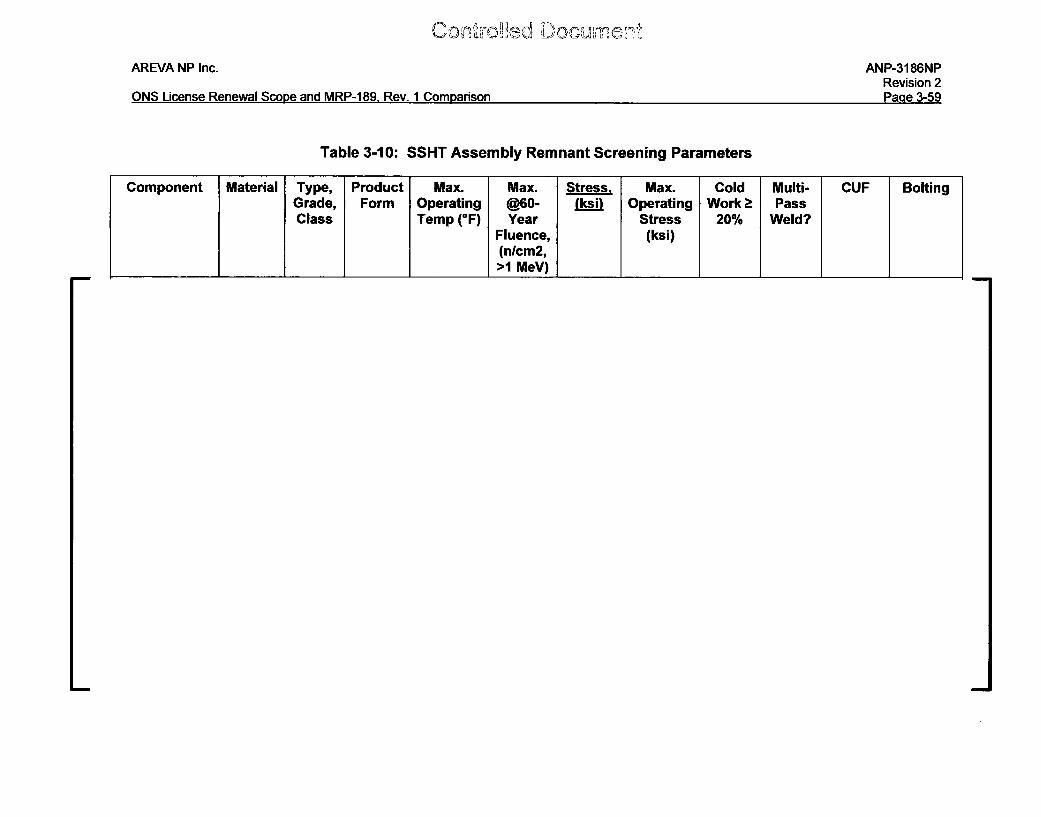
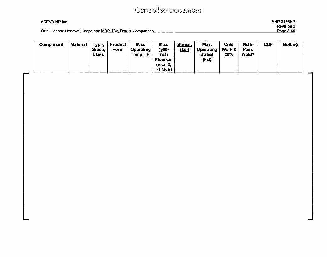
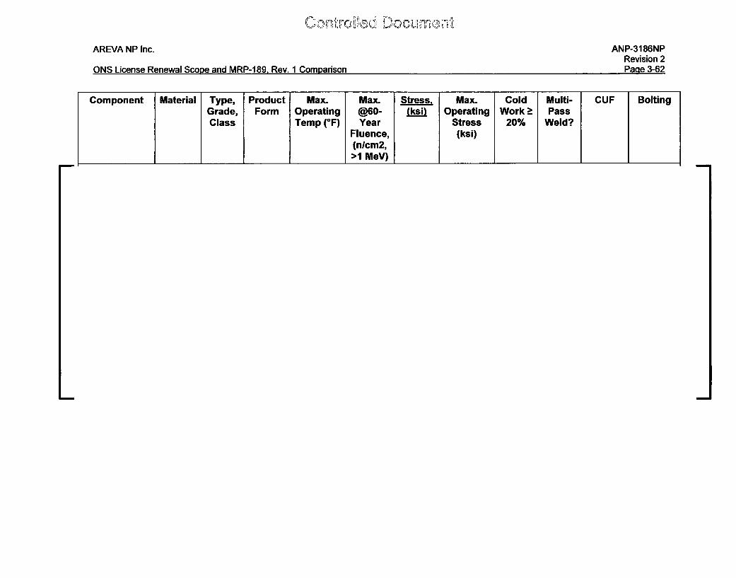
Table 3-10: SSHT Assembly Remnant Screening Parameters ................................. 3-59
Table 3-11: SSHT Remnant Initial Screening Results ............................................... 3-67
Table 3-12: SSHT Remnant Item FMECA Results .................................................... 3-74
Table 3-13: Preliminary Categorization of SSHT Remnant Component Items .......... 3-76
Con',Doce Doc;umeij-
AREVA NP Inc.
ONS License Renewal Scope and MRP-1 89, Rev. 1 Comparison
ANP-3186NPRevision 2
Page iv
List of Figures
Figure 3-1: Original Vent Valve Locking Device Schematic ...................................... 3-25
Figure 3-2: Original Vent Valve Locking Device Schematic - Cross-Section View ... 3-26
Figure 3-3: Modified Vent Valve Locking Device Schematic ..................................... 3-27
Figure 3-4: Modified Vent Valve Locking Device Schematic- Cross-Section View.. 3-28
Figure 3-5 MRP-189, Rev. I Screening Criteria ........................................................ 3-35
Figure 3-6 FMECA Risk Band (Safety or Economic) ................................................. 3-40
Figure 3-7: Location of Original Surveillance Specimen Holder Tube in B&W-DesignR eactor V essel Internals ....................................................................... 3-53
Figure 3-8: Original Surveillance Specimen Holder Tube Design in B&W-DesignR eactor V essel Internals ....................................................................... 3-54
Controfled Document
AREVA NP Inc. ANP-3186NPRevision 2
ONS License Renewal Scope and MRP-189, Rev. 1 Comparison Page 1-1
1.0 INTRODUCTION
In December 2008, Electric Power Research Institute (EPRI) issued Rev. 0 of the
Materials Reliability Program (MRP) MRP-227 [i] Inspection and Evaluation (I&E)
Guidelines for managing long-term aging of pressurized water reactor (PWR) reactor
vessel (RV) internals in the U.S. MRP-227-Rev. 0 was submitted to the Nuclear
Regulatory Commission (NRC) for review and approval in January 2009. [ii] In June
2011, the safety evaluation report (SER) for MRP-227-Rev. 0 was issued by the NRC
[iii] and was revised to Rev. 1 in December 2011 [iv]; the revised Rev. 1 SER is
included in the NRC-approved MRP-227-A report. [v] MRP-227-A provides generic
augmented inspection requirements for the currently operating fleet of U.S. PWRs.
MRP-227-A Section 7.3 categorizes the implementation of the augmented inspections
as "Needed" in accordance with Nuclear Energy Institute (NEI) 03-08 Guidelines. [vi]
Section 3.0 of Rev. 1 of the SER documents the staffs evaluation and findings
pertaining to the adequacy of the MRP's Aging Management Program (AMP)
recommendations. In particular, Section 3.0 documents staff concerns with MRP-227
and the basis for limitations and conditions being placed on the use of MRP-227 as well
as licensee/applicant action items that shall be addressed by applicants/licensees who
choose to implement the NRC-approved version of MRP-227.
Duke Energy plans to implement MRP-227-A for the Oconee Nuclear Station (ONS)
Units 1, 2, and 3 and in doing so, must perform the appropriate evaluation, analyses,
and other required actions to fulfill the applicant/licensee action items specified in the
SER. Applicant/licensee action item 2, from Section 4.2.2 of Rev. 1 of the SER, is as
follows:
Cto~e~d DocumentnAREVA NP Inc. ANP-3186NP
Revision 2ONS License Renewal Scope and MRP-189, Rev. 1 Comparison Page 1-2
"As discussed in Section 3.2.5.2 of this SE, consistent with the requirements
addressed in 10 CFR 54.4, each applicant/licensee is responsible for identifying
which RVI components are within the scope of LR for its facility.
Applicants/licensees shall review the information in Tables 4-1 and 4-2 in MRP-
189, Revision 1, and Tables 4-4 and 4-5 in MRP-191 and identify whether these
tables contain all of the RVI components that are within the scope of LR for their
facilities in accordance with 10 CFR 54.4. If the tables do not identify all the RVI
components that are within the scope of LR for its facility, the applicant or
licensee shall identify the missing component(s) and propose any necessary
modifications to the program defined in MRP-227, as modified by this SE, when
submitting its plant-specific AMP. The AMP shall provide assurance that the
effects of aging on the missing component(s) will be managed for the period of
extended operation. This issue is Applicant/Licensee Action Item 2."
The purpose of this document is to perform a comparison between the ONS RV
Internals license renewal (LR) scope and Tables 4-1 and 4-2 in MRP-189, Rev. 1 [vii]
(for B&W-designed RV Internals) to satisfy Applicant/Licensee Action Item 2 from
Reference iv. This comparison will identify whether the MRP-1 89, Rev. 1 tables contain
all of the RV Internals components that are within the scope of LR for the ONS units.
Information considered by AREVA to be proprietary is bracketed using the following
brackets: [ ]
AREVA NP Inc. ANP-3186NPRevision 2
ONS License Renewal Scope and MRP-1 89, Rev. 1 Comparison Page 2-1
2.0 METHODOLOGY
The methodology of the comparison described in Section 1.0 was to take the steps as
follows:
1. Obtain definition of scope for license renewal (located within 10 CFR 54.4 [viii])(Section 3.1 of this report)
2. Identify the scope of the license renewal for ONS RV Internals (contained in aDuke calculation) (Section 3.1.1 of this report)
3. List component items and welds contained in the scope (Section 3.1.1 of thisreport)
4. List component items and welds contained in MRP-189, Rev. 1 Tables 4-1 and 4-2 (Section 3.1.2 of this report)
5. Compare component items and identify whether the MRP-1 89, Rev. 1 tablescontain all of the RV Internals component items and welds that are within thescope of LR for the ONS units (Section 3.1.2, Section 3.2, Table 3-1, andTable 3-2 of this report)
6. Once the component items that are in the LR scope (but are not in MRP-189,Rev. 1) are identified, propose any necessary modifications to the programdefined in MRP-227, as modified by the SER (Section 3.3 of this report). Thiswill be done by utilizing the same screening methodology as used to developMRP-227-A. As described in MRP-227-A, the following sequence steps wereused:
a. Identify PWR internals components, materials, and environments
b. Identify degradation screening criteria
c. Characterize components and screen for degradation (A, non-A)
d. FMECA review
e. Severity categorization (A, B, C)
f. Engineering evaluation and assessment
g. Categorize for inspection (primary, expansion, existing, no additionalmeasures) and aging management strategy
Co'ýrdiled DoccumentAREVA NP Inc. ANP-3186NP
Revision 2ONS License Renewal Scope and MRP-1 89, Rev. 1 Comparison Page 3-1
3.0 COMPARISON
The following sections execute the methodology described in Section 2.0 of this report.
3.1 Scope Definition
The following definition of scope, for LR, is found in 10 CFR 54.4.
"(a) Plant systems, structures, and components within the scope of this part are--(1) Safety-related systems, structures, and components which are those relied upon to remainfunctional during and following design-basis events (as defined in 10 CFR 50. 49 (b)(1)) to ensurethe following functions--
(i) The integrity of the reactor coolant pressure boundary;(ii) The capability to shut down the reactor and maintain it in a safe shutdown condition;
or(iii) The capability to prevent or mitigate the consequences of accidents which couldresult in potential offsite exposures comparable to those referred to in § 50.34(a)(1), §50. 67(b)(2), or § 100.11 of this chapter, as applicable.
(2) All nonsafety-related systems, structures, and components whose failure could preventsatisfactory accomplishment of any of the functions identified in paragraphs (a)(1)(i), (ii), or (iii)of this section.(3) All systems, structures, and components relied on in safety analyses or plant evaluations toperform afunction that demonstrates compliance with the Commission's regulations for fireprotection (10 CFR 50.48), environmental qualification (10 CFR 50.49), pressurized thermalshock (10 CFR 50.61), anticipated transients without scram (10 CFR 50.62), and station blackout(10 CFR 50.63).
(b) The intended functions that these systems, structures, and components must be shown to fulfill in §54.21 are those functions that are the bases for including them within the scope of license renewal asspecified in paragraphs (a)(1) - (3) of this section. "
Con'mfoled DociiimerAREVA NP Inc. ANP-3186NP
Revision 2ONS License Renewal Scope and MRP-189, Rev. 1 Comparison Page 3-2
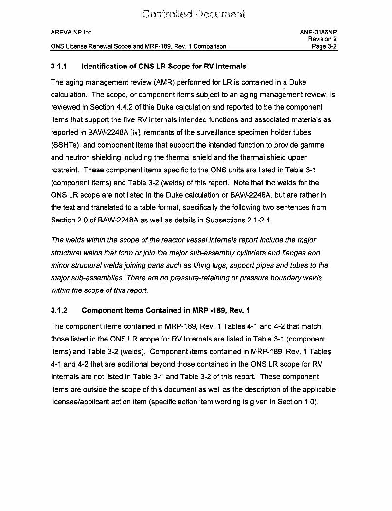
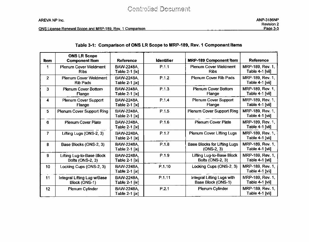
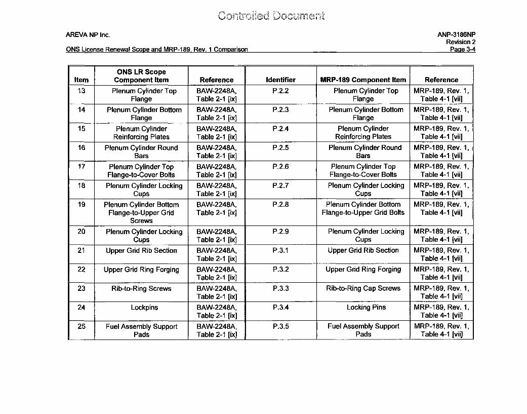
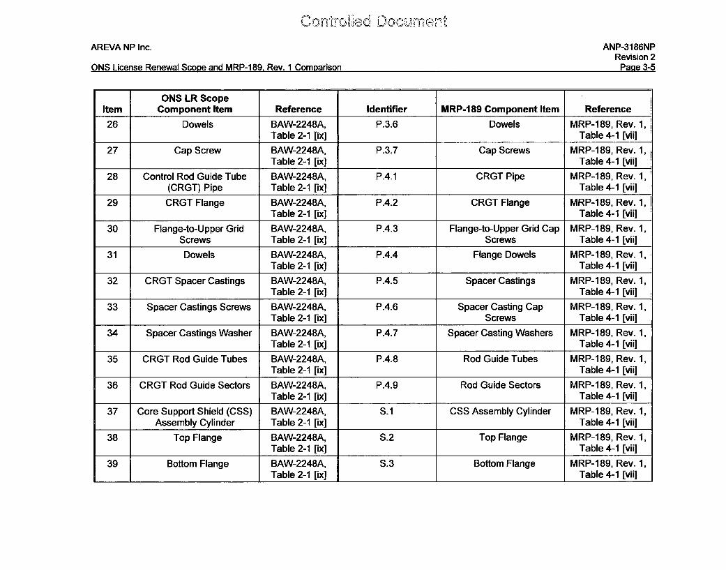
3.1.1 Identification of ONS LR Scope for RV Internals
The aging management review (AMR) performed for LR is contained in a Duke
calculation. The scope, or component items subject to an aging management review, is
reviewed in Section 4.4.2 of this Duke calculation and reported to be the component
items that support the five RV internals intended functions and associated materials as
reported in BAW-2248A [ix], remnants of the surveillance specimen holder tubes
(SSHTs), and component items that support the intended function to provide gamma
and neutron shielding including the thermal shield and the thermal shield upper
restraint. These component items specific to the ONS units are listed in Table 3-1
(component items) and Table 3-2 (welds) of this report. Note that the welds for the
ONS LR scope are not listed in the Duke calculation or BAW-2248A, but are rather in
the text and translated to a table format, specifically the following two sentences from
Section 2.0 of BAW-2248A as well as details in Subsections 2.1-2.4:
The welds within the scope of the reactor vessel internals report include the major
structural welds that form or join the major sub-assembly cylinders and flanges and
minor structural welds joining parts such as lifting lugs, support pipes and tubes to the
major sub-assemblies. There are no pressure-retaining or pressure boundary welds
within the scope of this report.
3.1.2 Component Items Contained in MRP -189, Rev. 1
The component items contained in MRP-189, Rev. 1 Tables 4-1 and 4-2 that match
those listed in the ONS LR scope for RV Internals are listed in Table 3-1 (component
items) and Table 3-2 (welds). Component items contained in MRP-189, Rev. 1 Tables
4-1 and 4-2 that are additional beyond those contained in the ONS LR scope for RV
Internals are not listed in Table 3-1 and Table 3-2 of this report. These component
items are outside the scope of this document as well as the description of the applicable
licensee/applicant action item (specific action item wording is given in Section 1.0).
Ccn,, -a
AREVA NP Inc.
ONS License Renewal Scope and MRP-1 89, Rev. I Comparison
ANP-3186NPRevision 2
Pane 3-3
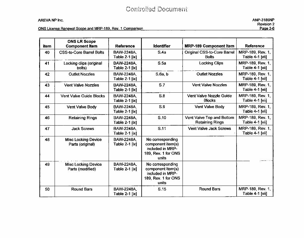
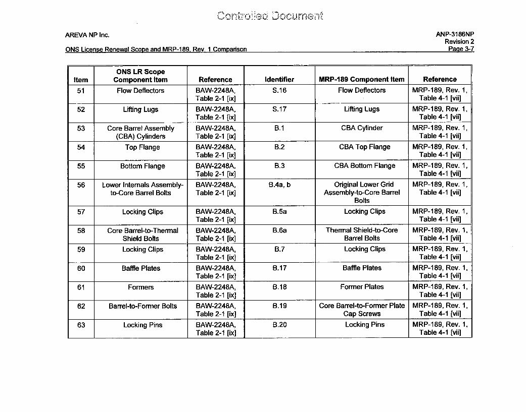
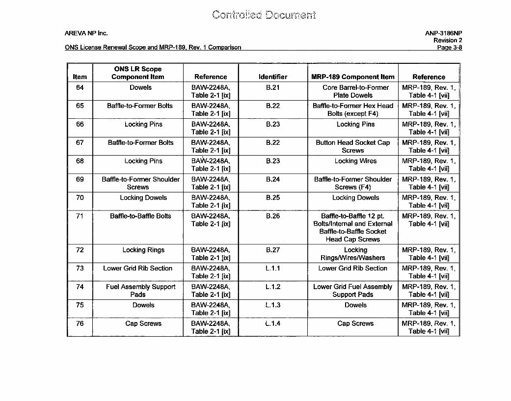
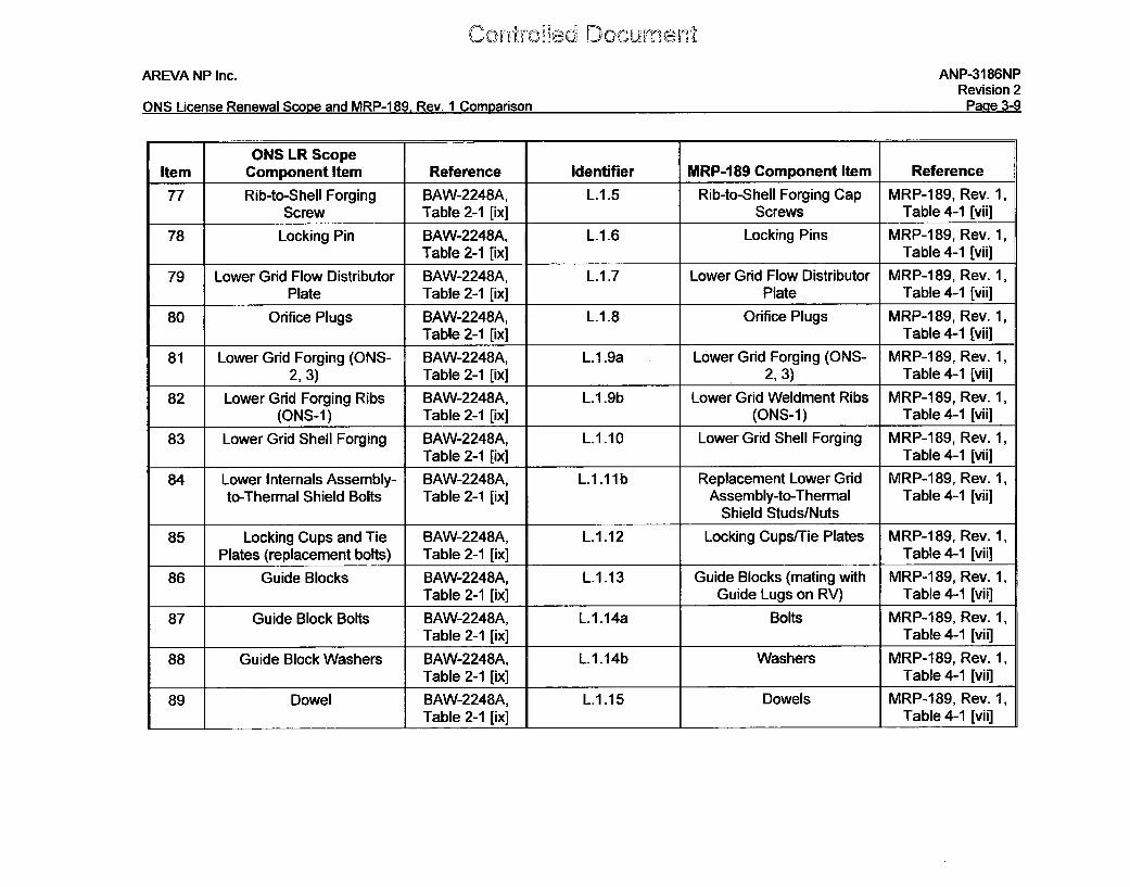
Table 3-1: Comparison of ONS LR Scope to MRP-189, Rev. I Component Items
ONS LR ScopeItem Component Item Reference Identifier MRP-189 Component Item Reference
1 Plenum Cover Weldment BAW-2248A, P.1.1 Plenum Cover Weldment MRP-189, Rev. 1,Ribs Table 2-1 [ix] Ribs Table 4-1 [vii]
2 Plenum Cover Weldment BAW-2248A, P.1.2 Plenum Cover Rib Pads MRP-189, Rev. 1,Rib Pads Table 2-1 [ix] Table 4-1 [vii]
3 Plenum Cover Bottom BAW-2248A, P.1.3 Plenum Cover Bottom MRP-189, Rev. 1,Flange Table 2-1 [ix] Flange Table 4-1 [vii]
4 Plenum Cover Support BAW-2248A, P.1.4 Plenum Cover Support MRP-189, Rev. 1,Flange Table 2-1 [ix] Flange Table 4-1 [vii]
5 Plenum Cover Support Ring BAW-2248A, P.1.5 Plenum Cover Support Ring MRP-189, Rev. 1,Table 2-1 [ix] Table 4-1 [vii]
6 Plenum Cover Plate BAW-2248A, P.1.6 Plenum Cover Plate MRP-189, Rev. 1,Table 2-1 [ix] Table 4-1 [vii]
7 Lifting Lugs (ONS-2, 3) BAW-2248A, P.1.7 Plenum Cover Lifting Lugs MRP-189, Rev. 1,Table 2-1 [ix] Table 4-1 [vii]
8 Base Blocks (ONS-2, 3) BAW-2248A, P.1.8 Base Blocks for Lifting Lugs MRP-189, Rev. 1,Table 2-1 [ix] (ONS-2, 3) Table 4-1 [vii]
9 Lifting Lug-to-Base Block BAW-2248A, P.1.9 Lifting Lug-to-Base Block MRP-189, Rev. 1,Bolts (ONS-2, 3) Table 2-1 [ix] Bolts (ONS-2, 3) Table 4-1 [vii]
10 Locking Cups (ONS-2, 3) BAW-2248A, P.1.10 Locking Cups (ONS-2, 3) MRP-189, Rev. 1,Table 2-1 [ix] Table 4-1 [vii]
11 Integral Lifting Lug w/Base BAW-2248A, P.1.11 Integral Lifting Lugs with MRP-189, Rev. 1,Block (ONS-1) Table 2-1 [ix] Base Block (ONS-1) Table 4-1 [vii]
12 Plenum Cylinder BAW-2248A, P.2.1 Plenum Cylinder MRP-189, Rev. 1,Table 2-1 [ix] Table 4-1 [vii]
1ý , 0 C; ilu rn Ci
AREVA NP Inc. ANP-3186NPRevision 2
Dý 2A-fn~iQ I i -me Daff--nI 4Z- anne RADD 1UO40 0-~ 1 ('amforea~nV~I .I . ltllI ICQ I\ •II•vwaI JU M~C~lA,V•III ~I~ \ - IU IJ I\ V I JtlI•/II hMOI ,/uII I OILI r•
ONS LR ScopeItem Component Item Reference Identifier MRP-189 Component Item Reference
13 Plenum Cylinder Top BAW-2248A, P.2.2 Plenum Cylinder Top MRP-189, Rev. 1,Flange Table 2-1 [ix] Flange Table 4-1 [vii]
14 Plenum Cylinder Bottom BAW-2248A, P.2.3 Plenum Cylinder Bottom MRP-189, Rev. 1,Flange Table 2-1 [ix] Flange Table 4-1 [vii]
15 Plenum Cylinder BAW-2248A, P.2.4 Plenum Cylinder MRP-189, Rev. 1,Reinforcing Plates Table 2-1 [ix] Reinforcing Plates Table 4-1 [vii]
16 Plenum Cylinder Round BAW-2248A, P.2.5 Plenum Cylinder Round MRP-189, Rev. 1,Bars Table 2-1 [ix] Bars Table 4-1 [vii]
17 Plenum Cylinder Top BAW-2248A, P.2.6 Plenum Cylinder Top MRP-189, Rev. 1,Flange-to-Cover Bolts Table 2-1 [ix] Flange-to-Cover Bolts Table 4-1 [vii]
18 Plenum Cylinder Locking BAW-2248A, P.2.7 Plenum Cylinder Locking MRP-189, Rev. 1,Cups Table 2-1 [ix] Cups Table 4-1 [vii]
19 Plenum Cylinder Bottom BAW-2248A, P.2.8 Plenum Cylinder Bottom MRP-189, Rev. 1,Flange-to-Upper Grid Table 2-1 [ix] Flange-to-Upper Grid Bolts Table 4-1 [vii]
Screws20 Plenum Cylinder Locking BAW-2248A, P.2.9 Plenum Cylinder Locking MRP-1 89, Rev. 1,
Cups Table 2-1 [ix] Cups Table 4-1 [vii]
21 Upper Grid Rib Section BAW-2248A, P.3.1 Upper Grid Rib Section MRP-189, Rev. 1,Table 2-1 [ix] Table 4-1 [vii]
22 Upper Grid Ring Forging BAW-2248A, P.3.2 Upper Grid Ring Forging MRP-189, Rev. 1,Table 2-1 [ix] Table 4-1 [vii]
23 Rib-to-Ring Screws BAW-2248A, P.3.3 Rib-to-Ring Cap Screws MRP-189, Rev. 1,Table 2-1 [ix] Table 4-1 [vii]
24 Lockpins BAW-2248A, P.3.4 Locking Pins MRP-189, Rev. 1,Table 2-1 [ix] Table 4-1 [vii]
25 Fuel Assembly Support BAW-2248A, P.3.5 Fuel Assembly Support MRP-189, Rev. 1,Pads Table 2-1 [ix] Pads Table 4-1 [vii]
0~ o urnc0,
AREVA NP Inc.
ONS License Renewal Scope and MRP-1 89, Rev. 1 Comparison
ANP-3186NPRevision 2
Page 3-5
ONS LR ScopeItem Component Item Reference Identifier MRP-189 Component Item Reference
26 Dowels BAW-2248A, P.3.6 Dowels MRP-189, Rev. 1,Table 2-1 [ix] Table 4-1 [vii]
27 Cap Screw BAW-2248A, P.3.7 Cap Screws MRP-189, Rev. 1,Table 2-1 [ix] Table 4-1 [vii]
28 Control Rod Guide Tube BAW-2248A, P.4.1 CRGT Pipe MRP-189, Rev. 1,(CRGT) Pipe Table 2-1 [ix] Table 4-1 [vii]
29 CRGT Flange BAW-2248A, P.4.2 CRGT Flange MRP-1189, Rev. 1,Table 2-1 [ix] Table 4-1 [vii]
30 Flange-to-Upper Grid BAW-2248A, P.4.3 Flange-to-Upper Grid Cap MRP-189, Rev. 1,Screws Table 2-1 [ix] Screws Table 4-1 [vii]
31 Dowels BAW-2248A, P.4.4 Flange Dowels MRP-189, Rev. 1,Table 2-1 [ix] Table 4-1 [vii]
32 CRGT Spacer Castings BAW-2248A, P.4.5 Spacer Castings MRP-189, Rev. 1,Table 2-1 [ix] Table 4-1 [vii]
33 Spacer Castings Screws BAW-2248A, P.4.6 Spacer Casting Cap MRP-189, Rev. 1,Table 2-1 [ix] Screws Table 4-1 [vii]
34 Spacer Castings Washer BAW-2248A, P.4.7 Spacer Casting Washers MRP-1189, Rev. 1,Table 2-1 [ix] Table 4-1 [vii]
35 CRGT Rod Guide Tubes BAW-2248A, P.4.8 Rod Guide Tubes MRP-189, Rev. 1,Table 2-1 [ix] Table 4-1 [vii]
36 CRGT Rod Guide Sectors BAW-2248A, P.4.9 Rod Guide Sectors MRP-189, Rev. 1,Table 2-1 [ix] Table 4-1 [vii]
37 Core Support Shield (CSS) BAW-2248A, S.1 CSS Assembly Cylinder MRP-1189, Rev. 1,Assembly Cylinder Table 2-1 [ix] Table 4-1 [vii]
38 Top Flange BAW-2248A, S.2 Top Flange MRP-189, Rev. 1,Table 2-1 [ix] Table 4-1 [vii]
39 Bottom Flange BAW-2248A, S.3 Bottom Flange MRP-189, Rev. 1,Table 2-1 [ix] Table 4-1 [vii]
AREVA NP Inc. ANP-3186NPRevision 2
Da nl "rn~eI ; Da,~, 14 A RADDj 120 0n I r, A nrnnUJl ,VJ LlleII OC F•I IGlm V l ttAJ1tO OIItS IVII\*--IU 1\. I t I, l OE lll I %OtUR as-tJ
ONS LR ScopeItem Component Item Reference Identifier MRP-189 Component Item Reference
40 CSS-to-Core Barrel Bolts BAW-2248A, S.4a Original CSS-to-Core Barrel MRP-189, Rev. 1,Table 2-1 [ix] Bolts Table 4-1 [vii]
41 Locking clips (original BAW-2248A, S.5a Locking Clips MRP-189, Rev. 1,bolts) Table 2-1 [ix] Table 4-1 [vii]
42 Outlet Nozzles BAW-2248A, S.6a, b Outlet Nozzles MRP-189, Rev. 1,Table 2-1 [ix] Table 4-1 [vii]
43 Vent Valve Nozzles BAW-2248A, S.7 Vent Valve Nozzles MRP-189, Rev. 1,Table 2-1 [ix] Table 4-1 [vii]
44 Vent Valve Guide Blocks BAW-2248A, S.8 Vent Valve Nozzle Guide MRP-189, Rev. 1,Table 2-1 [ix] Blocks Table 4-1 [vii]
45 Vent Valve Body BAW-2248A, S.9 Vent Valve Body MRP-189, Rev. 1,Table 2-1 [ix] Table 4-1 [vii]
46 Retaining Rings BAW-2248A, S.10 Vent Valve Top and Bottom MRP-189, Rev. 1,Table 2-1 [ix] Retaining Rings Table 4-1 [vii]
47 Jack Screws BAW-2248A, S.11 Vent Valve Jack Screws MRP-189, Rev. 1,Table 2-1 [ix] Table 4-1 [vii]
48 Misc Locking Device BAW-2248A, No correspondingParts (original) Table 2-1 [ix] component item(s)
included in MRP-189, Rev. I for ONS
units
49 Misc Locking Device BAW-2248A, No correspondingParts (modified) Table 2-1 [ix] component item(s)
included in MRP-189, Rev. 1 for ONS
units
50 Round Bars BAW-2248A, S.15 Round Bars MRP-189, Rev. 1,Table 2-1 [ix] Table 4-1 [vii]
AREVA NP Inc. ANP-3186NPRevision 2
PIon• aq-7flKIC I mnne DnnI Icn a'r A 10 RAD10 Dan 1 ('rnnnrmAn•l,.Ji~~ t LI u. I * HOVII N '.Jt J Uli IVI\I----l I I V. . U .=n , WI•
ONS LR ScopeItem Component Item Reference Identifier MRP-189 Component Item Reference
51 Flow Deflectors BAW-2248A, S.16 Flow Deflectors MRP-189, Rev. 1,Table 2-1 [ix] Table 4-1 [vii]
52 Lifting Lugs BAW-2248A, S.17 Lifting Lugs MRP-189, Rev. 1,Table 2-1 [ix] Table 4-1 [vii]
53 Core Barrel Assembly BAW-2248A, B.1 CBA Cylinder MRP-189, Rev. 1,(CBA) Cylinders Table 2-1 [ix] Table 4-1 [vii]
54 Top Flange BAW-2248A, B.2 CBA Top Flange MRP-189, Rev. 1,Table 2-1 [ix] Table 4-1 [vii]
55 Bottom Flange BAW-2248A, B.3 CBA Bottom Flange MRP-189, Rev. 1,Table 2-1 [ix] Table 4-1 [vii]
56 Lower Internals Assembly- BAW-2248A, B.4a, b Original Lower Grid MRP-189, Rev. 1,to-Core Barrel Bolts Table 2-1 [ix] Assembly-to-Core Barrel Table 4-1 [vii]
Bolts
57 Locking Clips BAW-2248A, B.5a Locking Clips MRP-189, Rev. 1,Table 2-1 [ix] Table 4-1 [vii]
58 Core Barrel-to-Thermal BAW-2248A, B.6a Thermal Shield-to-Core MRP-189, Rev. 1,Shield Bolts Table 2-1 [ix] Barrel Bolts Table 4-1 [vii]
59 Locking Clips BAW-2248A, B.7 Locking Clips MRP-189, Rev. 1,Table 2-1 [ix] Table 4-1 [vii]
60 Baffle Plates BAW-2248A, B.17 Baffle Plates MRP-189, Rev. 1,Table 2-1 [ix] Table 4-1 [vii]
61 Formers BAW-2248A, B.18 Former Plates MRP-189, Rev. 1,Table 2-1 [ix] Table 4-1 [vii]
62 Barrel-to-Former Bolts BAW-2248A, B.19 Core Barrel-to-Former Plate MRP-189, Rev. 1,Table 2-1 [ix] Cap Screws Table 4-1 [vii]
63 Locking Pins BAW-2248A, B.20 Locking Pins MRP-189, Rev. 1,Table 2-1 [ix] Table 4-1 [vii]
ConL)V!,jand
AREVA NP Inc. ANP-3186NPRevision 2
Pzni a q.RC~M5~ I iron~ P~n~u~I 5~v'nng~ ~n,1 MRP~1 RQ Pj~u I C~nmn~rknn
ONS LR ScopeItem Component Item Reference Identifier MRP-189 Component Item Reference
64 Dowels BAW-2248A, B.21 Core Barrel-to-Former MRP-189, Rev. 1,Table 2-1 [ix] Plate Dowels Table 4-1 [vii]
65 Baffle-to-Former Bolts BAW-2248A, B.22 Baffle-to-Former Hex Head MRP-189, Rev. 1,Table 2-1 [ix] Bolts (except F4) Table 4-1 [vii]
66 Locking Pins BAW-2248A, B.23 Locking Pins MRP-189, Rev. 1,Table 2-1 [ix] Table 4-1 [vii]
67 Baffle-to-Former Bolts BAW-2248A, B.22 Button Head Socket Cap MRP-189, Rev. 1,Table 2-1 [ix] Screws Table 4-1 [vii]
68 Locking Pins BAW-2248A, B.23 Locking Wires MRP-189, Rev. 1,Table 2-1 [ix] Table 4-1 [vii]
69 Baffle-to-Former Shoulder BAW-2248A, B.24 Baffle-to-Former Shoulder MRP-189, Rev. 1,Screws Table 2-1 [ix] Screws (F4) Table 4-1 [vii]
70 Locking Dowels BAW-2248A, B.25 Locking Dowels MRP-189, Rev. 1,Table 2-1 [ix] Table 4-1 [vii]
71 Baffle-to-Baffle Bolts BAW-2248A, B.26 Baffle-to-Baffle 12 pt. MRP-189, Rev. 1,Table 2-1 [ix] Bolts/Internal and External Table 4-1 [vii]
Baffle-to-Baffle SocketHead Cap Screws
72 Locking Rings BAW-2248A, B.27 Locking MRP-189, Rev. 1,Table 2-1 [ix] Rings/Wires/Washers Table 4-1 [vii]
73 Lower Grid Rib Section BAW-2248A, L.1.1 Lower Grid Rib Section MRP-189, Rev. 1,Table 2-1 [ix] Table 4-1 [vii]
74 Fuel Assembly Support BAW-2248A, L.1.2 Lower Grid Fuel Assembly MRP-189, Rev. 1,Pads Table 2-1 [ix] Support Pads Table 4-1 [vii]
75 Dowels BAW-2248A, L.1.3 Dowels MRP-189, Rev. 1,Table 2-1 [ix] Table 4-1 [vii]
76 Cap Screws BAW-2248A, L.1.4 Cap Screws MRP-189, Rev. 1,Table 2-1 [ix] Table 4-1 [vii]
AREVA NP Inc. ANP-3186NPRevision 2
DM = 'A-0^~KW- I ; 10 A AIAD - O 4 r, AU..JI'I % LII."I r i %•lCW/i ..3 A.I. a[lU IV11W- -I 1, V . I 1l,, IUl IIUI I I. v-
ONS LR ScopeItem Component Item Reference Identifier MRP-189 Component Item Reference
77 Rib-to-Shell Forging BAW-2248A, L.1.5 Rib-to-Shell Forging Cap MRP-189, Rev. 1,Screw Table 2-1 [ix] Screws Table 4-1 [vii]
78 Locking Pin BAW-2248A, L.1.6 Locking Pins MRP-189, Rev. 1,Table 2-1 [ix] Table 4-1 [vii]
79 Lower Grid Flow Distributor BAW-2248A, L.1.7 Lower Grid Flow Distributor MRP-189, Rev. 1,Plate Table 2-1 [ix] Plate Table 4-1 [vii]
80 Orifice Plugs BAW-2248A, L.1.8 Orifice Plugs MRP-189, Rev. 1,Table 2-1 [ix] Table 4-1 [vii]
81 Lower Grid Forging (ONS- BAW-2248A, L.1.9a Lower Grid Forging (ONS- MRP-189, Rev. 1,2, 3) Table 2-1 [ix] 2, 3) Table 4-1 [vii]
82 Lower Grid Forging Ribs BAW-2248A, L.1.9b Lower Grid Weldment Ribs MRP-189, Rev. 1,(ONS-1) Table 2-1 [ix] (ONS-1) Table 4-1 [vii]
83 Lower Grid Shell Forging BAW-2248A, L.1.10 Lower Grid Shell Forging MRP-189, Rev. 1,Table 2-1 [ix] Table 4-1 [vii]
84 Lower Internals Assembly- BAW-2248A, L.1.11 b Replacement Lower Grid MRP-189, Rev. 1,to-Thermal Shield Bolts Table 2-1 [ix] Assembly-to-Thermal Table 4-1 [vii]
Shield Studs/Nuts
85 Locking Cups and Tie BAW-2248A, L.1.12 Locking Cups/Tie Plates MRP-189, Rev. 1,Plates (replacement bolts) Table 2-1 [ix] Table 4-1 [vii]
86 Guide Blocks BAW-2248A, L.1.13 Guide Blocks (mating with MRP-189, Rev. 1,Table 2-1 [ix] Guide Lugs on RV) Table 4-1 [vii]
87 Guide Block Bolts BAW-2248A, L.1.14a Bolts MRP-189, Rev. 1,Table 2-1 [ix] Table 4-1 [vii]
88 Guide Block Washers BAW-2248A, L.1.14b Washers MRP-189, Rev. 1,Table 2-1 [ix] Table 4-1 [vii]
89 Dowel BAW-2248A, L.1.15 Dowels MRP-189, Rev. 1,Table 2-1 [ix] Table 4-1 [vii]
S~Thc~iec~ LJo~um~mtAREVA NP Inc. ANP-3186NP
Revision 2PDnc. aL-ifnfleI I inao Dannoa 1(2n .nA RADD 120 D-t, I f--rnnnen
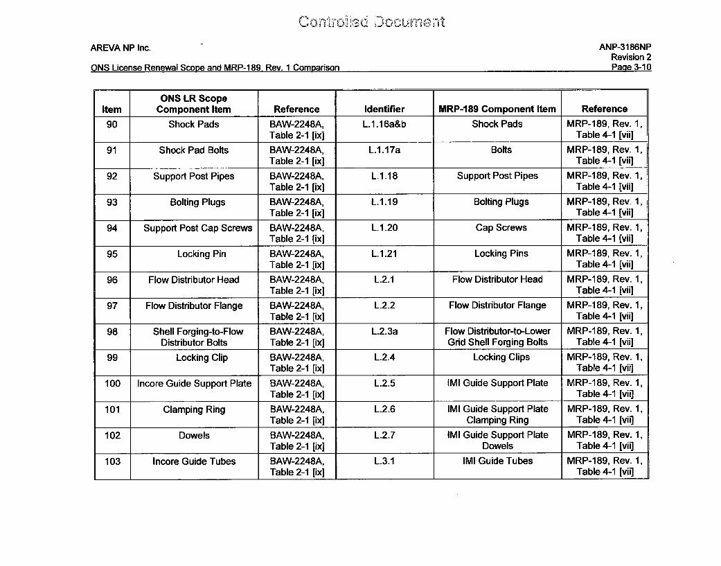
ONS LR ScopeItem Component Item Reference Identifier MRP-189 Component Item Reference
90 Shock Pads BAW-2248A, L.1.16a&b Shock Pads MRP-189, Rev. 1,Table 2-1 [ix] Table 4-1 [vii]
91 Shock Pad Bolts BAW-2248A, L.1.17a Bolts MRP-189, Rev. 1,Table 2-1 [ix] Table 4-1 [vii]
92 Support Post Pipes BAW-2248A, L.1.18 Support Post Pipes MRP-189, Rev. 1,Table 2-1 [ix] Table 4-1 [vii]
93 Bolting Plugs BAW-2248A, L.1.19 Bolting Plugs MRP-189, Rev. 1,Table 2-1 [ix] Table 4-1 [vii]
94 Support Post Cap Screws BAW-2248A, L.1.20 Cap Screws MRP-189, Rev. 1,Table 2-1 [ix] Table 4-1 [vii]
95 Locking Pin BAW-2248A, L.1.21 Locking Pins MRP-189, Rev. 1,Table 2-1 [ix] Table 4-1 [vii]
96 Flow Distributor Head BAW-2248A, L.2.1 Flow Distributor Head MRP-189, Rev. 1,Table 2-1 [ix] Table 4-1 [vii]
97 Flow Distributor Flange BAW-2248A, L.2.2 Flow Distributor Flange MRP-1189, Rev. 1,Table 2-1 [ix] Table 4-1 [vii]
98 Shell Forging-to-Flow BAW-2248A, L.2.3a Flow Distributor-to-Lower MRP-189, Rev. 1,Distributor Bolts Table 2-1 [ix] Grid Shell Forging Bolts Table 4-1 [vii]
99 Locking Clip BAW-2248A, L.2.4 Locking Clips MRP-189, Rev. 1,Table 2-1 [ix] Table 4-1 [vii]
100 Incore Guide Support Plate BAW-2248A, L.2.5 IMI Guide Support Plate MRP-189, Rev. 1,Table 2-1 [ix] Table 4-1 [vii]
101 Clamping Ring BAW-2248A, L.2.6 IMI Guide Support Plate MRP-189, Rev. 1,Table 2-1 [ix] Clamping Ring Table 4-1 [vii]
102 Dowels BAW-2248A, L.2.7 IMI Guide Support Plate MRP-189, Rev. 1,Table 2-1 [ix] Dowels Table 4-1 [vii]
103 Incore Guide Tubes BAW-2248A, L.3.1 IMI Guide Tubes MRP-189, Rev. 1,Table 2-1 [ix] Table 4-1 [vii]
11.1mAREVA NP Inc. ANP-3186NP
Revision 2P~nn .'-11I
AMC I ~ ~ ~ ~n,4 P.ADD.jI flO D~i I Cw~mv~rienn
ONS LR ScopeItem Component Item Reference Identifier MRP-189 Component Item Reference
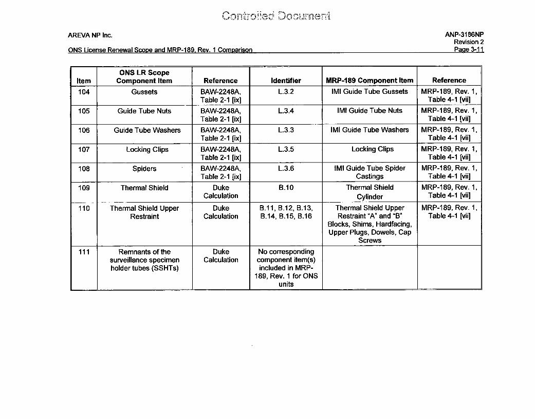
104 Gussets BAW-2248A, L.3.2 IMI Guide Tube Gussets MRP-189, Rev. 1,Table 2-1 [ix] Table 4-1 [vii]
105 Guide Tube Nuts BAW-2248A, L.3.4 IMI Guide Tube Nuts MRP-189, Rev. 1,Table 2-1 [ix] Table 4-1 [vii]
106 Guide Tube Washers BAW-2248A, L.3.3 IMI Guide Tube Washers MRP-189, Rev. 1,Table 2-1 [ix] Table 4-1 [vii]
107 Locking Clips BAW-2248A, L.3.5 Locking Clips MRP-189, Rev. 1,Table 2-1 [ix] Table 4-1 [vii]
108 Spiders BAW-2248A, L.3.6 IMI Guide Tube Spider MRP-189, Rev. 1,Table 2-1 [ix] Castings Table 4-1 [vii]
109 Thermal Shield Duke B.10 Thermal Shield MRP-189, Rev. 1,Calculation Cylinder Table 4-1 [vii]
110 Thermal Shield Upper Duke B.11, B.12, B.13, Thermal Shield Upper MRP-189, Rev. 1,Restraint Calculation B.14, B.15, B.16 Restraint "A" and "B" Table 4-1 [vii]
Blocks, Shims, Hardfacing,Upper Plugs, Dowels, Cap
Screws
111 Remnants of the Duke No correspondingsurveillance specimen Calculation component item(s)holder tubes (SSHTs) included in MRP-
189, Rev. 1 for ONSunits
Conrdfled Docunnen,,"1
AREVA NP Inc. ANP-3186NPRevision 2D • 4')nmeI ; 0 1C ARAD -100 De, -1 (',.,
%.uIJ I"IOQrV i~q-VVa %,AULM CA"i IvI - , VV. V I l.JuIIaI HOw" I .
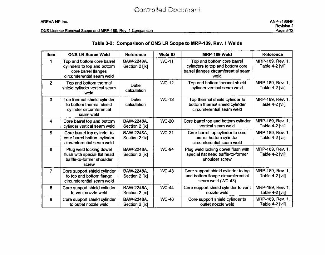
Table 3-2: Comparison of ONS LR Scope to MRP-189, Rev. I Welds
Item ONS LR Scope Weld Reference Weld ID MRP-189 Weld Reference
1 Top and bottom core barrel BAW-2248A, WC-1 1 Top and bottom core barrel MRP-189, Rev. 1,cylinders to top and bottom Section 2 [ix] cylinders to top and bottom core Table 4-2 [vii]
core barrel flanges barrel flanges circumferential seamcircumferential seam weld weld
2 Top and bottom thermal Duke WC-12 Top and bottom thermal shield MRP-189, Rev. 1,shield cylinder vertical seam calculation cylinder vertical seam weld Table 4-2 [vii]
weld
3 Top thermal shield cylinder Duke WC-13 Top thermal shield cylinder to MRP-189, Rev. 1,to bottom thermal shield calculation bottom thermal shield cylinder Table 4-2 [vii]cylinder circumferential circumferential seam weld
seam weld
4 Core barrel top and bottom BAW-2248A, WC-20 Core barrel top and bottom cylinder MRP-189, Rev. 1,cylinder vertical seam weld Section 2 [ix] vertical seam weld Table 4-2 [vii]
5 Core barrel top cylinder to BAW-2248A, WC-21 Core barrel top cylinder to core MRP-189, Rev. 1,core barrel bottom cylinder Section 2 [ix] barrel bottom cylinder Table 4-2 [vii]circumferential seam weld circumferential seam weld
6 Plug weld locking dowel BAW-2248A, WC-94 Plug weld locking dowel flush with MRP-189, Rev. 1,flush with special flat head Section 2 [ix] special flat head baffle-to-former Table 4-2 [vii]baffle-to-former shoulder shoulder screw
screw
7 Core support shield cylinder BAW-2248A, WC-43 Core support shield cylinder to top MRP-189, Rev. 1,to top and bottom flange Section 2 [ix] and bottom flange circumferential Table 4-2 [vii]
circumferential seam weld seam weld (WC-43)
8 Core support shield cylinder BAW-2248A, WC-44 Core support shield cylinder to vent MRP-189, Rev. 1,to vent nozzle weld Section 2 [ix] nozzle weld Table 4-2 [vii]
9 Core support shield cylinder BAW-2248A, WC-46 Core support shield cylinder to MRP-189, Rev. 1,to outlet nozzle weld Section 2 [ix] outlet nozzle weld Table 4-2 [vii]
AREVA NP Inc. ANP-3186NPRevision 2PO a q-1,-to(nMQ I i,-neý Qý^u~ n nrl PtADD-12 P~w 1~ Pn ( ýrmnae~n
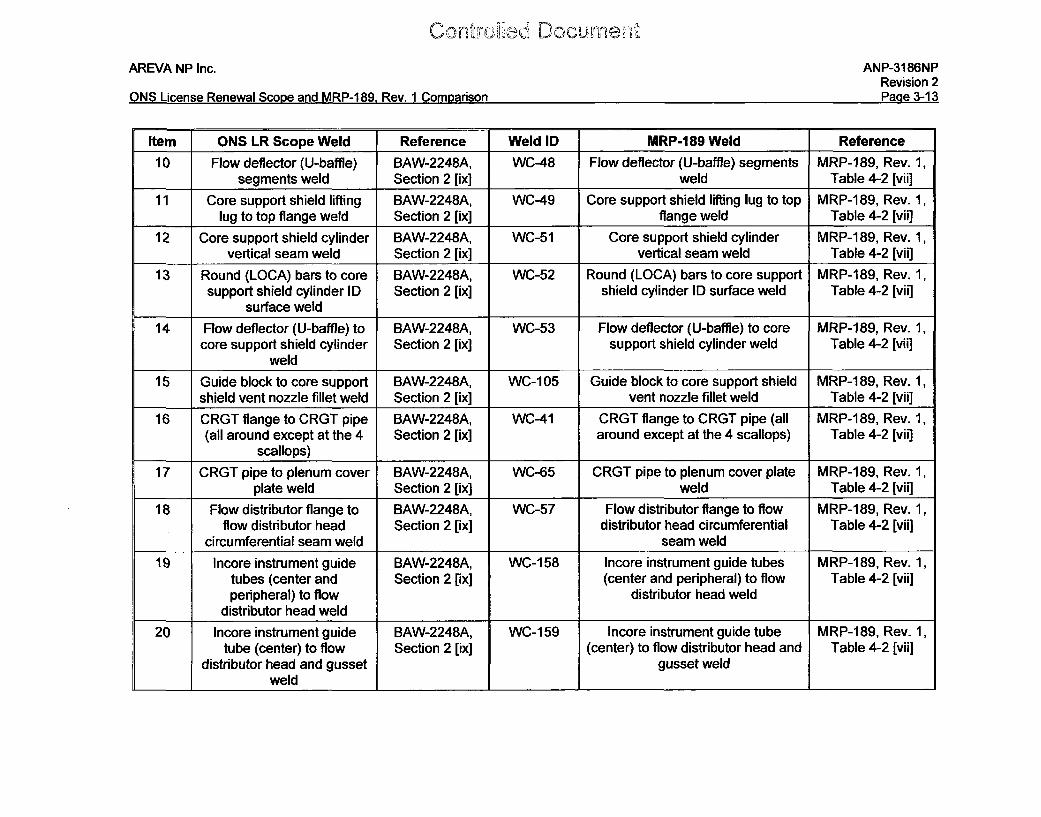
Item ONS LR Scope Weld Reference Weld ID MRP-189 Weld Reference
10 Flow deflector (U-baffle) BAW-2248A, WC-48 Flow deflector (U-baffle) segments MRP-189, Rev. 1,segments weld Section 2 [ix] weld Table 4-2 [vii]
11 Core support shield lifting BAW-2248A, WC-49 Core support shield lifting lug to top MRP-189, Rev. 1,lug to top flange weld Section 2 [ix] flange weld Table 4-2 [vii]
12 Core support shield cylinder BAW-2248A, WC-51 Core support shield cylinder MRP-189, Rev. 1,vertical seam weld Section 2 [ix] vertical seam weld Table 4-2 [vii]
13 Round (LOCA) bars to core BAW-2248A, WC-52 Round (LOCA) bars to core support MRP-189, Rev. 1,support shield cylinder ID Section 2 [ix] shield cylinder ID surface weld Table 4-2 [vii]
surface weld14 Flow deflector (U-baffle) to BAW-2248A, WC-53 Flow deflector (U-baffle) to core MRP-189, Rev. 1,
core support shield cylinder Section 2 [ix] support shield cylinder weld Table 4-2 [vii]weld
15 Guide block to core support BAW-2248A, WC-105 Guide block to core support shield MRP-189, Rev. 1,shield vent nozzle fillet weld Section 2 [ix] vent nozzle fillet weld Table 4-2 [vii]
16 CRGT flange to CRGT pipe BAW-2248A, WC-41 CRGT flange to CRGT pipe (all MRP-189, Rev. 1,(all around except at the 4 Section 2 [ix] around except at the 4 scallops) Table 4-2 [vii]
scallops)
17 CRGT pipe to plenum cover BAW-2248A, WC-65 CRGT pipe to plenum cover plate MRP-189, Rev. 1,plate weld Section 2 [ix] weld Table 4-2 [vii]
18 Flow distributor flange to BAW-2248A, WC-57 Flow distributor flange to flow MRP-189, Rev. 1,flow distributor head Section 2 [ix] distributor head circumferential Table 4-2 [vii]
circumferential seam weld seam weld
19 Incore instrument guide BAW-2248A, WC-158 Incore instrument guide tubes MRP-189, Rev. 1,tubes (center and Section 2 [ix] (center and peripheral) to flow Table 4-2 [vii]peripheral) to flow distributor head weld
distributor head weld
20 Incore instrument guide BAW-2248A, WC-159 Incore instrument guide tube MRP-189, Rev. 1,tube (center) to flow Section 2 [ix] (center) to flow distributor head and Table 4-2 [vii]
distributor head and gusset gusset weldweld _ I I I _I
Uor"If-6 aI'D, CTh2 llC, I
AREVA NP Inc. ANP-3186NPRevision 2Page 3-14ONS License Renewal Scope and MRP-1 89, Rev. 1 Comparison
Item ONS LR Scope Weld Reference Weld ID MRP-189 Weld Reference
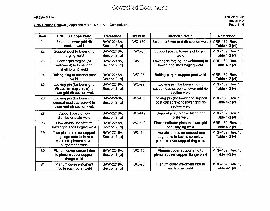
21 Spider to lower grid rib BAW-2248A, WC-160 Spider to lower grid rib section weld MRP-189, Rev. 1,section weld Section 2 [ix] Table 4-2 [vii]
22 Support post to lower grid BAW-2248A, WC-5 Support post to lower grid forging MRP-189, Rev. 1,forging weld Section 2 [ix] weld Table 4-2 [vii]
23 Lower grid forging (or BAW-2248A, WC-8 Lower grid forging (or weldment) to MRP-189, Rev. 1,weldment) to lower grid Section 2 [ix] lower grid shell forging weld Table 4-2 [vii]
shell forging weld
.24 Bolting plug to support post BAW-2248A, WC-97 Bolting plug to support post weld MRP-189, Rev. 1,weld Section 2 [ix] Table 4-2 [vii]
25 Locking pin (for lower grid BAW-2248A, WC-99 Locking pin (for lower grid rib MRP-189, Rev. 1,rib section cap screw) to Section 2 [ix] section cap screw) to lower grid rib Table 4-2 [vii]
lower grid rib section weld section weld
26 Locking pin (for lower grid BAW-2248A, WC-100 Locking pin (for lower grid support MRP-189, Rev. 1,support post cap screw) to Section 2 [ix] post cap screw) to lower grid rib Table 4-2 [vii]lower grid rib section weld section weld
27 Support post to flow BAW-2248A, WC-142 Support post to flow distributor MRP-189, Rev. 1,distributor plate weld Section 2 [ix] plate weld Table 4-2 [vii]
28 Flow distributor plate to BAW-2248A, WC-142 Flow distributor plate to lower grid MRP-189, Rev. 1,lower grid shell forging weld Section 2 [ix] shell forging weld Table 4-2 [vii]
29 Two plenum cover support BAW-2248A, WC-18 Two plenum cover support ring MRP-189, Rev. 1,ring segments to form a Section 2 [ix] segments to form a complete Table 4-2 [vii]complete plenum cover plenum cover support ring weld
support ring weld
30 Plenum cover support ring BAW-2248A, WC-19 Plenum cover support ring to MRP-189, Rev. 1,to plenum cover support Section 2 [ix] plenum cover support flange weld Table 4-2 [vii]
flange weld
31 Plenum cover weldment BAW-2248A, WC-28 Plenum cover weldment ribs to MRP-189, Rev. 1,ribs to each other weld Section 2 [ix] I each other weld Table 4-2 [vii]
AREVA NP Inc. ANP-3186NPRevision 2PZn1 a -1,-;AN5~ I ~ P~ni~w~aI ~r~nn~ ~nrI MPP-IRQ R~~, I Cnmn2riQnn
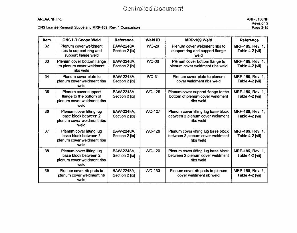
Item ONS LR Scope Weld Reference Weld ID MRP-1 89 Weld Reference32 Plenum cover weldment BAW-2248A, WC-29 Plenum cover weldment ribs to MRP-189, Rev. 1,
ribs to support ring and Section 2 [ix] support ring and support flange Table 4-2 [vii]support flange weld weld
33 Plenum cover bottom flange BAW-2248A, WC-30 Plenum cover bottom flange to MRP-189, Rev. 1,to plenum cover weldment Section 2 [ix] plenum cover weldment ribs weld Table 4-2 [vii]
ribs weld
34 Plenum cover plate to BAW-2248A, WC-31 Plenum cover plate to plenum MRP-189, Rev. 1,plenum cover weldment ribs Section 2 [ix] cover weldment ribs weld Table 4-2 [vii]
weld
35 Plenum cover support BAW-2248A, WC-126 Plenum cover support flange to the MRP-189, Rev. 1,flange to the bottom of Section 2 [ix] bottom of plenum cover weldment Table 4-2 [vii]
plenum cover weldment ribs ribs weldweld
36 Plenum cover lifting lug BAW-2248A, WC-127 Plenum cover lifting lug base block MRP-189, Rev. 1,base block between 2 Section 2 [ix] between 2 plenum cover weldment Table 4-2 [vii]
plenum cover weldment ribs ribs weldweld
37 Plenum cover lifting lug BAW-2248A, WC-128 Plenum cover lifting lug base block MRP-189, Rev. 1,base block between 2 Section 2 [ix] between 2 plenum cover weldment Table 4-2 [vii]
plenum cover weldment ribs ribs weldweld
38 Plenum cover lifting lug BAW-2248A, WC-129 Plenum cover lifting lug base block MRP-189, Rev. 1,base block between 2 Section 2 [ix] between 2 plenum cover weldment Table 4-2 [vii]
plenum cover weldment ribs ribs weldweld
39 Plenum cover rib pads to BAW-2248A, WC-133 Plenum cover rib pads to plenum MRP-1189, Rev. 1,plenum cover weldment rib Section 2 [ix] cover weldment rib weld Table 4-2 [vii]
weld II
AREVA NP Inc. ANP-3186NPRevision 2PMna ?1.t
.. . . ... . .... . .Licens . ... ..... .. S o e a d M 1 .. .. ... rR...... 1 .. ..arso
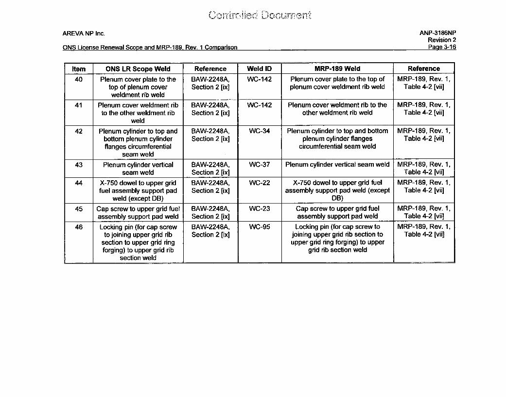
Item ONS LR Scope Weld Reference Weld ID MRP-189 Weld Reference
40 Plenum cover plate to the BAW-2248A, WC-142 Plenum cover plate to the top of MRP-189, Rev. 1,top of plenum cover Section 2 [ix] plenum cover weldment rib weld Table 4-2 [vii]weldment rib weld
41 Plenum cover weldment rib BAW-2248A, WC-142 Plenum cover weldment rib to the MRP-189, Rev. 1,to the other weldment rib Section 2 [ix] other weldment rib weld Table 4-2 [vii]
weld
42 Plenum cylinder to top and BAW-2248A, WC-34 Plenum cylinder to top and bottom MRP-189, Rev. 1,bottom plenum cylinder Section 2 [ix] plenum cylinder flanges Table 4-2 [vii]flanges circumferential circumferential seam weld
seam weld
43 Plenum cylinder vertical BAW-2248A, WC-37 Plenum cylinder vertical seam weld MRP-189, Rev. 1,seam weld Section 2 [ix] Table 4-2 [vii]
44 X-750 dowel to upper grid BAW-2248A, WC-22 X-750 dowel to upper grid fuel MRP-189, Rev. 1,fuel assembly support pad Section 2 [ix] assembly support pad weld (except Table 4-2 [vii]
weld (except DB) DB)
45 Cap screw to upper grid fuel BAW-2248A, WC-23 Cap screw to upper grid fuel MRP-189, Rev. 1,assembly support pad weld Section 2 [ix] assembly support pad weld Table 4-2 [vii]
46 Locking pin (for cap screw BAW-2248A, WC-95 Locking pin (for cap screw to MRP-189, Rev. 1,to joining upper grid rib Section 2 [ix] joining upper grid rib section to Table 4-2 [vii]
section to upper grid ring upper grid ring forging) to upperforging) to upper grid rib grid rib section weld
section weld
AREVA NP Inc. ANP-3186NPRevision 2
ONS License Renewal Scope and MRP-1 89, Rev. 1 Comparison Page 3-17
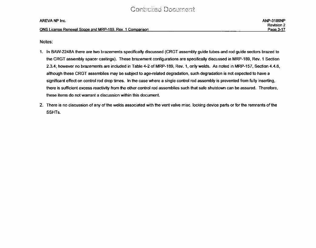
Notes:
1. In BAW-2248A there are two brazements specifically discussed (CRGT assembly guide tubes and rod guide sectors brazed to
the CRGT assembly spacer castings). These brazement configurations are specifically discussed in MRP-189, Rev. 1 Section
2.3.4; however no brazements are included in Table 4-2 of MRP-1 89, Rev. 1, only welds. As noted in MRP-1 57, Section 4.4.6,
although these CRGT assemblies may be subject to age-related degradation, such degradation is not expected to have a
significant effect on control rod drop times. In the case where a single control rod assembly is prevented from fully inserting,
there is sufficient excess reactivity from the other control rod assemblies such that safe shutdown can be assured. Therefore,
these items do not warrant a discussion within this document.
2. There is no discussion of any of the welds associated with the vent valve misc. locking device parts or for the remnants of the
SSHTs.
Conto~edD ocumbrni
AREVA NP Inc. ANP-3186NPRevision 2
ONS License Renewal Scope and MRP-189, Rev. 1 Comparison Page 3-18
3.2 Component Item Comparison
Table 3-1 and Table 3-2 of this report contain a comparison of the components items
and welds contained in the LR scope for the ONS RV Internals and MRP-189, Rev. 1.
As shown in the tables, three component items are contained in the LR scope for the
ONS RV Internals and are not identified in MRP-189, Rev. 1:
1. Vent Valve Misc. Locking Device Parts (original) (Table 3-1, item 48)
2. Vent Valve Misc. Locking Device Parts (modified) (Table 3-1, item 49)
3. Remnants of the SSHTs (Table 3-1, item 111)
Any necessary program modifications regarding items 48, 49, and 111 from Table 3-1 of
this report are discussed in Section 3.3 of this report.
It should be noted that in the Duke AMR in Section 4.4.3.2, the results of a peer review
conducted with the Oconee component engineers is described, and that an additional
aging effect not identified in BAW-2248A was documented. This aging effect was
I ] of the round bars (a.k.a. LOCA
[loss-of-coolant-accident] lugs or LOCA bosses). There are 13 of these round bars
welded to the outer surface of the plenum cylinder at each of the outlet nozzle areas.
These lugs are positioned opposite similar lugs welded to the inner surface of the CSS.
The two sets of lugs ensure that the radial clearance between the two cylinders is
maintained so that RCS (reactor coolant system) flow is not disrupted under any
conditions, including a LOCA.
MRP-189, Rev. 1 only identified SCC as a potential age-related degradation mechanism
and the FMECA expert panel considered it improbable for SCC to cause loss of most or
all of the round bars. It was also noted in Table 4-1 of MRP-189, Rev. 1 that current
ASME examination requirements (VT-3 during 10-year ISI examinations) should be
maintained and that these items should also be candidates for future inspection and
maintenance programs. Ultimately, these items were categorized as "Category A" and
"No Additional Measures."
C on'wýro He d D o . m a n
AREVA NP Inc. ANP-3186NPRevision 2
ONS License Renewal Scope and MRP-189, Rev. I Comparison Page 3-19
A review of the [ ] round bars on the CSS and plenum
assemblies indicates that
] Therefore, it is
concluded that [ ' of the round bars, during normal operation, is not a realistic
aging mechanism for consideration; however, [
] is a realistic degradation concern. It is also concluded that
current ASME Section Xl examinations during 10-year ISIs are adequate [
] and that the
MRP-1189, Rev. 1 screening and categorization results are adequate. No augmented
examinations are therefore needed.
Additionally, during a records search performed in 2009 and 2010, a feature unique to
ONS-1 was identified for the plenum cover weldment rib pads. Each of the 32 plenum
cover rib pads at ONS-1 is fastened to the plenum cover ribs with two Type 304 screws
and one Alloy X-750 dowel. At the six other operating B&W units, the plenum cover rib
pads are welded to the plenum cover weldment ribs. Since this unique feature was not
known during the preparatory work leading up to MRP-227-A or the initial scope work
performed for license renewal for the ONS units, the Alloy X-750 dowel and Type 304
screws and their locking welds at this location were not included in the ONS scope nor
evaluated in the MRP screening documents.
AREVA NP Inc. ANP-3186NPRevision 2
ONS License Renewal Scooe and MRP-189, Rev. 1 Comparison Page 3-20
AREVA previously performed a screening for the Alloy X-750 dowel, Alloy X-750 dowel
locking weld, Type 304 screws, and Type 304 screw locking welds. The screening was
performed using the same screening process and criteria that was used for other
locations and documented in MRP-189, Rev. 1. The Alloy X-750 dowel and the Type
304 screws and their locking welds were screened as Category "A" items. The Alloy X-
750 dowel locking welds were screened as Category "Not A" due to being potentially
susceptible to primary water SCC (PWSCC). However, a functionality assessment of
the Alloy X-750 dowel locking weld categorized this component item as "No Additional
Measures" per MRP-227-A. Therefore, no additional augmented inspection is required
for this location.
3.3 Program Modifications
This section discusses the background of the identified component items and any
program modifications necessary based on the identification of these component items
contained in the LR scope for the ONS RV Internals as discussed in Section 3.2 of this
report.
3.3.1 Misc. Locking Device Parts (Original and Modified)
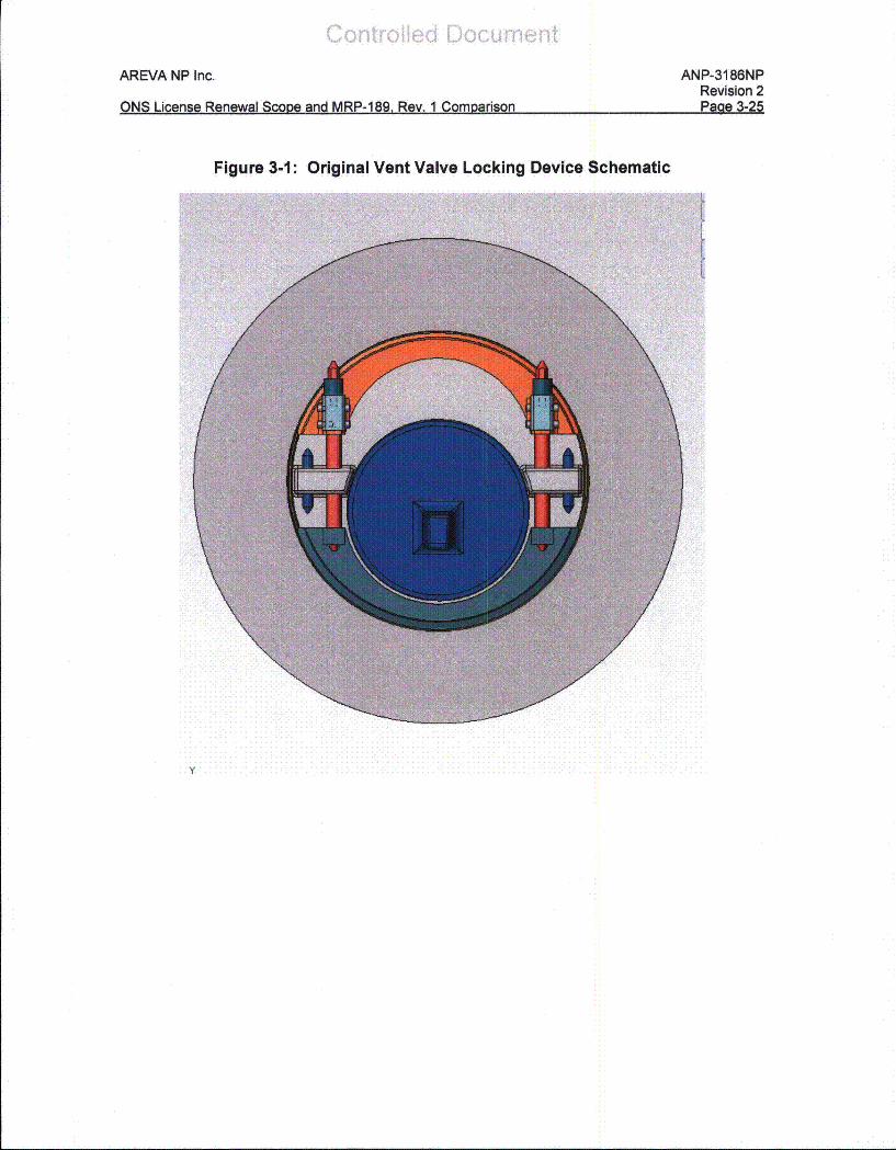
Section 3.2 of this report identifies component items contained in the LR scope for the
ONS RV Internals that are not contained in MRP-189, Rev. 1. Two of these component
items are the vent valve misc. locking device parts (both original and modified, see
Figure 3-1, Figure 3-2, Figure 3-3, and Figure 3-4 of this report).
AREVA NP Inc. ANP-3186NPRevision 2
ONS License Renewal Scope and MRP-189, Rev. 1 Comparison Page 3-21
Vent Valve Locking Device Background
During a routine inspection during a refueling outage in 1978 at one Babcock and
Wilcox (B&W) unit, [
] Further video inspection of the
valves revealed extensive damage to one valve and a lesser amount to another valve.
The damage was determined to be caused by [
Another B&W unit was advised to look for similar damage during their video inspection;
this inspection revealed a different problem, which was later determined to be wear
[ ] On one valve, the [
] had worn through and the front portion was missing, which allowed the
[ ] resulting in considerable wear on the
[ '1 On another valve, video inspection revealed a crack
in [ ]
After removal and physical inspection, the wear pattern on both valves were similar:
[ ] The
remaining two valves adjacent to the outlet nozzles were removed and inspected for
wear; wear was also seen.
The potential impact of the wear problem is the possibility of a loose part [
] moving to the steam generator and damaging the tubes and causing
a forced outage. Additionally, the loss of the locking function could [
] allow an increase in the core bypass flow.
Con',,'croflad Doc.urnan-i
AREVA NP Inc. ANP-3186NPRevision 2
ONS License Renewal Scope and MRP-1 89, Rev. 1 Comparison Page 3-22
A postulated initiator that caused the relative motion was deduced to be [
] The vent valves adjacent to the outlet
nozzles [
Following the discovery of the damage at the B&W unit, a design effort was started to
develop a replacement locking mechanism for the vent valves. The basic premise for
the design effort was [
] Prior to the removal of any
valves, a video inspection of each original jackscrew locking device was made and
abnormalities reported for evaluation. Instructions were such that if []
showed signs [
] , the [ ] valves should be removed, inspected, and each valve
modified [ ] with the new (modified) locking devices per the
appropriate field change package.
Contirofled DocumneMAREVA NP Inc.
ONS Lieanse Renewal Scooe and MRP-189. Rev. 1 Como}arison
ANP-3186NPRevision 2Paae 3-23
...... Lies ee a coeadM P19Rv 1... . Compriso "a 3-2
Additionally, in 1994 cracking of an Alloy 600 locking cup in the modified vent valve
design was observed at one B&W unit; approximately one half of the jack screw locking
cup was missing from one of the jackscrews on the affected vent valve. The affected
vent valve was [ ] replaced afterwards.
It was believed that this cracking was due to [
or impact damage from the plenum insertion and/or removal and
[ ]
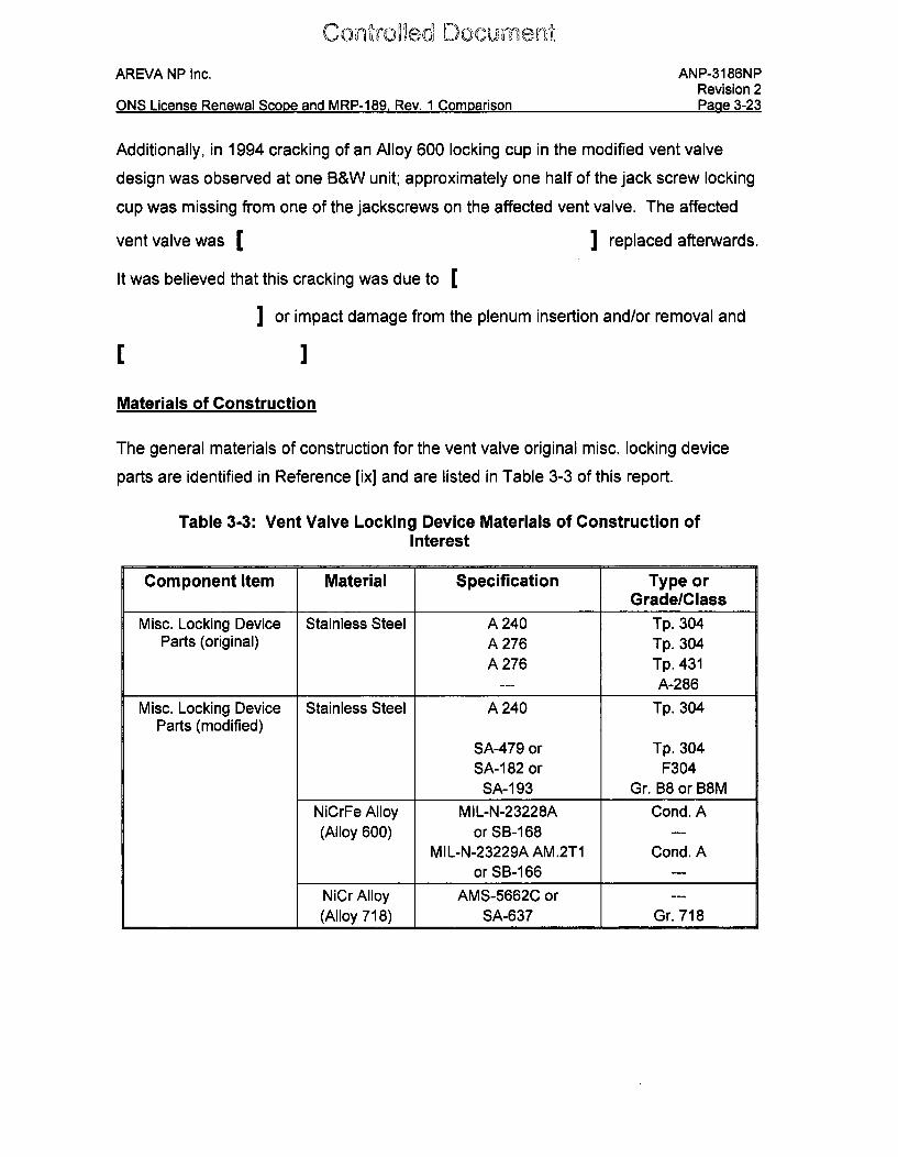
Materials of Construction
The general materials of construction for the vent valve original misc. locking device
parts are identified in Reference [ix] and are listed in Table 3-3 of this report.
Table 3-3: Vent Valve Locking Device Materials of Construction ofInterest
Component Item Material Specification Type orGrade/Class
Misc. Locking Device Stainless Steel A 240 Tp. 304Parts (original) A 276 Tp. 304
A 276 Tp. 431--- A-286
Misc. Locking Device Stainless Steel A 240 Tp. 304Parts (modified)
SA-479 or Tp. 304SA-182 or F304
SA-193 Gr. B8 or B8MNiCrFe Alloy MIL-N-23228A Cond. A(Alloy 600) or SB- 68 ---
MIL-N-23229A AM.2T1 Cond. Aor SB-166 ---
NiCr Alloy AMS-5662C or ---(Alloy 718) SA-637 Gr. 718
CcoMtmolled DocumenmAREVA NP Inc. ANP-3186NP
Revision 2ONS License Renewal Scope and MRP-189, Rev. 1 Comparison Page 3-24
Original field change authorizations (FCAs) indicate that B&W recommended the four
original vent valve locking devices on either side of the two outlet nozzles be replaced
with the modified vent valve locking devices at the three ONS units. Additionally, site
problem reports (SPRs) for the ONS units were reviewed. The following information
was located from the SPRs:
* ONS-3- [ ] four vent valves [] were removed from the CSS. Four vent valves, [
] with replaced jackscrew locking devices were installed to the
CSS. In addition, a [ ] vent valve was also removed and reinstalled afterfixing a jackscrew [ ] but without replacing the locking devices.
" ONS-2- [ I four vent valves [ Iwere removed from the CSS. Four vent valves, [
] with replaced jackscrew locking device were installed to the
CSS. []
* ONS-1 - [ ] field inspection of jackscrew locking devices on four
spare vent valves in a warehouse at the ONS site. Some [ ]jackscrew locking devices were found to be unacceptable and wererecommended to be shipped back to the original fabricator for correction. NoSPR related to ONS-1 replacement of the vent valves [
I was found during the records search.
However, a 2005 survey regarding vent valves indicates that each ONS unit replaced
four vent valves [ ] due to replacement of the jackscrew
locking devices. [
The original and modified vent valve locking device drawings as well as the parts to be
replaced and the modified locking device parts are identified in the FCAs; these parts
are listed in Table 3-4 of this report.
AREVA NP Inc. ANP-3186NPRevision 2p:a a I._9fllKIQ I i-nnea Panaual rnna Z anrl IAPP-1AC. P w I (1nmnariakn
I= am y --- Is Kx I x . x K x a
Figure 3-1: Original Vent Valve Locking Device Schematic
Y
A n.~
AREVA NP Inc. ANP-3186NPRevision 2pIna .nKMQ I it-fanag Pinv~n 4Zf-'r% anrl tAPID-1AO Paui 1 frnm nria,'n
Figure 3-2: Original Vent Valve Locking Device Schematic - Cross-Section View
,.UorW'uWropnd1 Document
AREVA NP Inc. ANP-3186NPRevision 2Dona =_-7efNKC I inae 0aane 1r4n Ar IACDD 100 Cc,, 4 rlnmn~nrie~n
Lt,VOI IOU VC %IWHI ="ll.I.U 1W ~E - h! %IQ U.I~tIIUIIII '~,a
Figure 3-3: Modified Vent Valve Locking Device Schematic
(C,'cntrd,,oHei Dcument
AREVA NP Inc. ANP-3186NPRevision 2Pmna .MQI it-imnad MmmaflAimm Qr mn, aml APP_1%AO Paw, 1 CPAm ria,%n
m te
Figure 3-4: Modified Vent Valve Locking Device Schematic-Cross-Section View
Controlid~ DocumentAREVA NP Inc. ANP-3186NP
Revision 2Pawe 3-29ONS License Renewal SCOoe and MRP-189. Rev. 1 Comoarison
ONS License Renewal ScoDe and MRP-189 Rev. 1 COMDarison
Table 3-4: Vent Valve Locking Device Material Identification
II
_1Original/Modified
Drawing PartNumber Part Description Material
y.nýu ~Tm Do] cument
AREVA NP Inc. ANP-3186NPRevision 2
ONS License Renewal Scope and MRP-189, Rev. 1 Comparison Page 3-30
3.3.1.1 Identification of Screening Parameters and Criteria
The screening parameters for the component items listed in Table 3-4 are tabulated in
Table 3-5. The environmental parameters for the component items listed in Table 3-4 of
this report are the same as for the other vent valve items (see Table 3-2 of MRP-1 89,
Rev. 1, identifiers S.7-S.14). The neutron fluence is less than 5E18 n/cm 2 (E > 1.0
MeV) and the temperature is 6050F. Operating stresses for the original and modified
vent valve locking device parts were not located during the preparation of this task. The
tack, plug, and fillet welds were not confirmed to be or not to be multi-pass welds, but
due to their small size, they are likely not multi-pass welds. A cold work value of greater
than or equal to 20% is expected for those component items in the modified vent valve
locking devices that are [ I
Controlled Document
AREVA NP Inc. ANP-3186NPRevision 2Dan= •-14
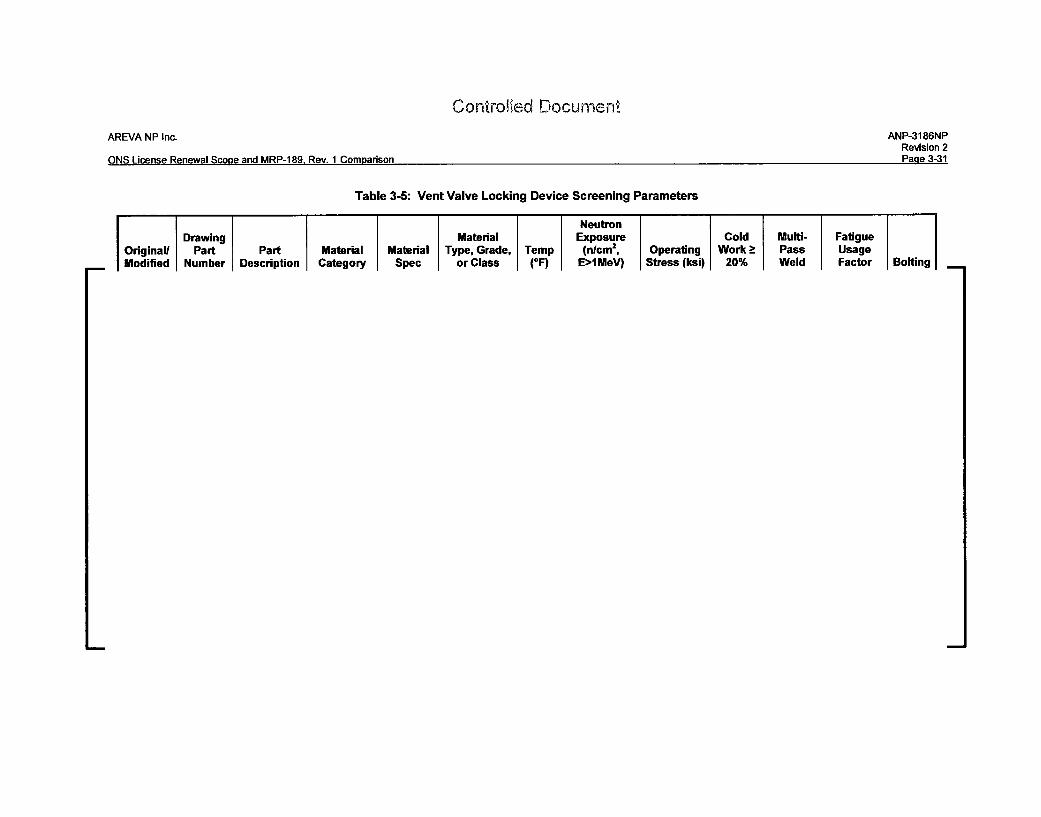
Table 3-5: Vent Valve Locking Device Screening Parameters
NeutronDrawing Material Exposure Cold Multi- Fatigue
Original, Part Part Material Material Type, Grade, Temp (nlcm2 , Operating Work > Pass UsageModified Number Description Category Spec or Class (OF) E>IMeV) Stress (ksi) 20% Weld Factor Bolting
Controlled Document
AREVA NP Inc. ANP-3186NPRevision 2
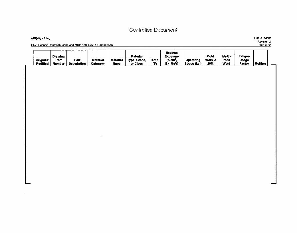
ONS License Renewal Scope and MRP-1 89. Rev. 1 Comparison Page 3-32
NeutronDrawing Material Exposure Cold Multi- Fatigue
Original) Part Part Material Material Type, Grade, Temp (nlcm 2, Operating Work > Pass UsageModified Number Description Category Spec or Class (*F) E>HMeV) Stress (ksi) 20% Weld Factor Bolting -
Controfled Docunien.AREVA NP Inc. ANP-3186NP
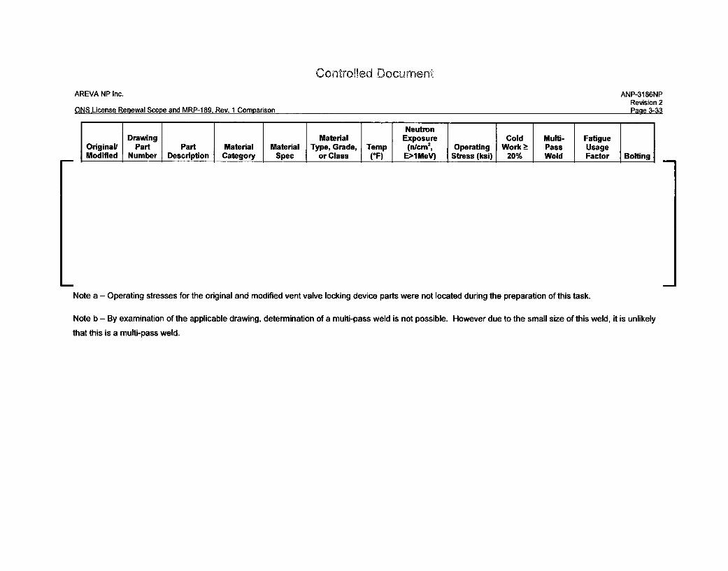
Revision 2ONS License Renewal Scope and MRP-1 89, Rev. 1 Comparison Page 3-33
NeutronDrawing Material Exposure Cold Mulif- Fatigue
Original/ Part Part Material Material Type, Grade, Temp (n/cm2, Operating Work - Pass UsageModified Number Description Category Spec or Class (*F) E>IMeV) Stress (ksi) 20% Weld Factor Bolting
Note a - Operating stresses for the original and modified vent valve locking device parts were not located during the preparation of this task.
Note b - By examination of the applicable drawing, determination of a multi-pass weld is not possible. However due to the small size of this weld, it is unlikely
that this is a multi-pass weld.
Contrd','ed 01ocurnent-
AREVA NP Inc. ANP-3186NPRevision 2
ONS License Renewal Scope and MRP-189, Rev. 1 Comparison Page 3-34
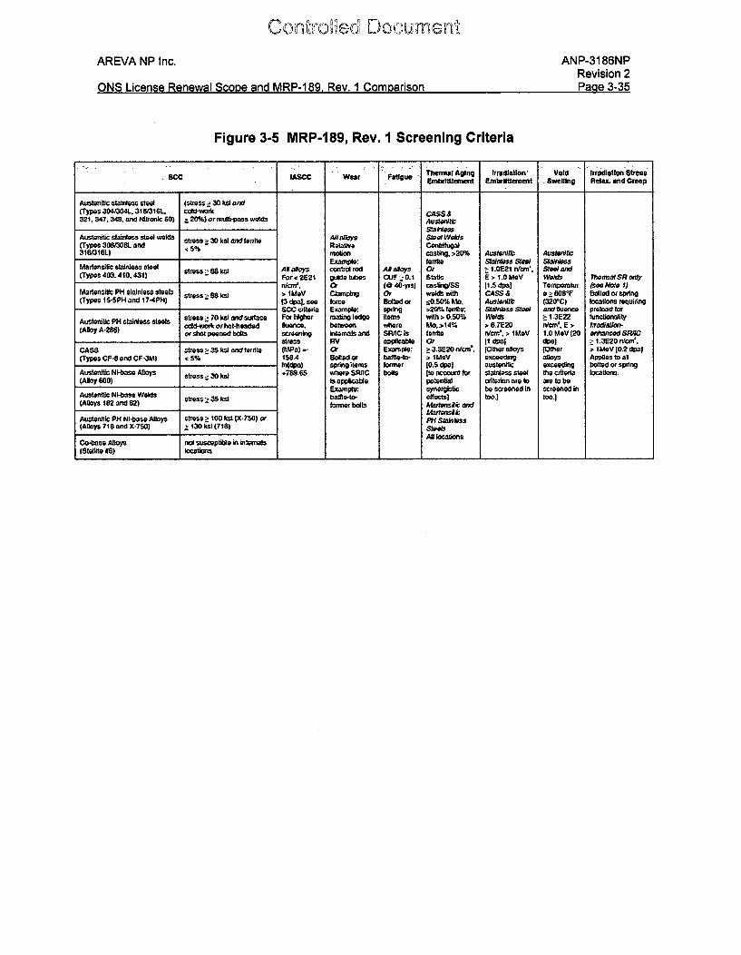
3.3.1.2 Characterize and Screen for Degradation
The original and modified vent valve locking device items for the three ONS units
identified in Table 3-4 of this report need to be screened using the screening process
and criteria that has been used for other RV Internals component items and
documented in MRP-189, Rev. 1, and Section 3. The screening criteria used are those
detailed in Table 3-1 of MRP-189, Rev. 1. This table is repeated as Figure 3-5 of this
report. Each age-related degradation mechanism is screened for each PWR internals
component item by comparing the values in Table 3-5 against the screening criteria in
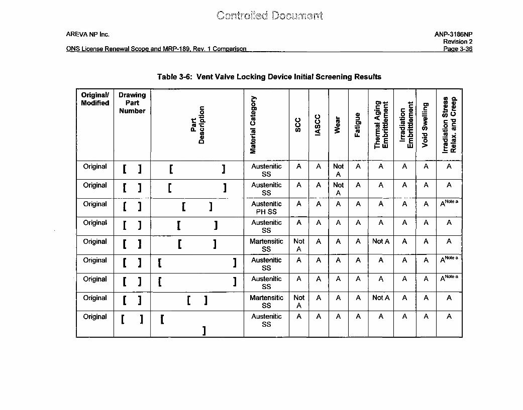
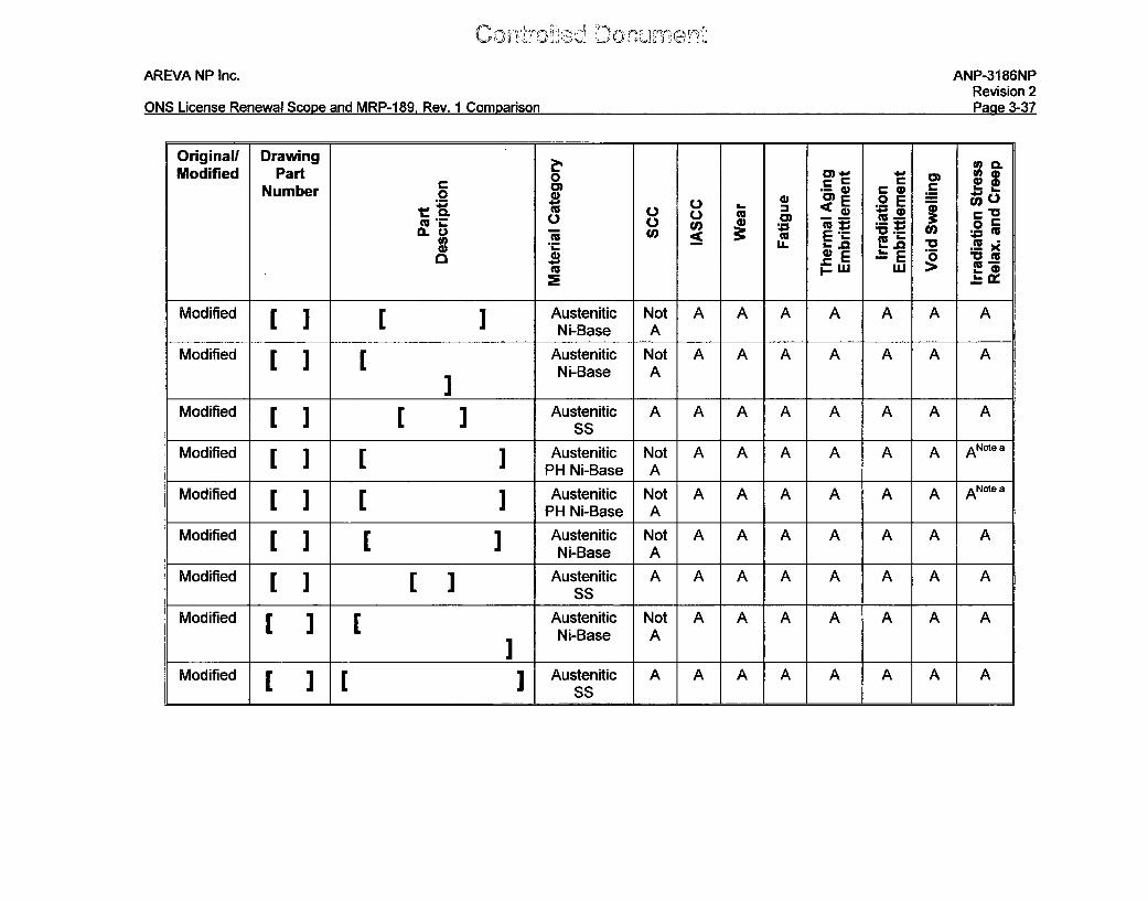
Figure 3-5 and the results are contained in Table 3-6 of this report. An aging
mechanism is screened in if the screening criteria are met or exceeded for that
component item. Otherwise, the aging mechanism is screened out for the component
item. If a value is unknown (e.g., operating stress), it is assumed to have exceeded the
applicable screening criteria.
AREVA NP Inc. ANP-3186NPRevision 2Do dal -':nflQl I iae Danaaa I Qtnf on,
1 *ADD 100 DOn. '^m flmorienn%,I"QW W.~.O WICC ýWhI Q050 lJ'U W11. VI~ ~ 0.I~I110 C1 U
Figure 3-5 MRP-189, Rev. 1 Screening Criteria
ScC LASCC wear Fatigue Thermal Aging Irradiation' Void Irradiation Stres.E• bettlement E.brtlement Swelling Relam and Creep
Ausolentlc slarinoss steel (stress .30 kM and(Types 30403041.. 31 (3161. cIld-woIC CASS&32f, 347. 348, and Nilronkc 60) 120%) or0rmli-pass wedf Austwlcd
SMak#ess
Austenitc stainless steel welds stress a 30 ksli ax-d ferite ARlasj Ctol.walds(Types 3083081. and 5% Rlato Cantrih*3,31M/3161) motion casting, >20% Austaniftt AusteardU
Motlenpli sta"les 01.01I tanlsMaTponsii¢ stai 43403 stress> 68 lst Alaloys control rod A#aloys O : 10E21 nr/'. 51eW and(Typos 403. 400, 431) _____ ______For < 2E21 guidelibes CUF - 0.1 Static E > 1.0 MeV Welds wennaISR only
nMtg, or (e 46-yrs) cas•Qr/SS [1.,3 pa) Temrperatut (see Note $)Martensilc PH stsnlesfa stoa stressSsi > imav Clomping •f Welds wth CASS & 9 > 608F Bolted or spring(Types 16-5PN and 17-4P) [3 dpa). see lorce Bed or 40.50% Mo. Aust"e, (320C) locations requiring
SCC criteria Example spring >20% ferufte; S.dtaiss StoW and fluance preload for
Austenitic PH stan, stesls stress0 70 ksli and surface For gerw mating ledge items with > 0.50% We"ds 2:13E22 functionatliycold-work orhot-headed lee. bsrwen where M. W>14% 8 6.7E20 rdcm', E' > rz~aiatfon-
(AoyA-28) or shotoned bots screening intemals and SRIC Is froite Wma.> I MeV 1.0MeV [20 enhancodSR/lC
stress RV apprllcble o0 [l 3 dpo} > 1.3E2O nrcn.CASS stress ! 35 ksl ande frrite (Mta) -- or Example: a 3.3E20 nfcn. [Olher•alloys Other 1 tMeV [0.2 dpa](Types CF-8 and CF-3M) <5% t58.4 sowed or baffle-io- MI eV iceedai alloys Aplies to all
Fn(10) spring Items lormel [0.5 dpal austerdtic exceeding bolted or springAustteniic Ni-base Alloys s 3789.66 VAW' SR1AC boaS Ito account W stainless steel the criteria locatis.(Alloy 600) is aplictablo polenAcliterion are to are to be
ExarnWe: syeogsbc be scrooned in creene inAuster82ic N-be Welds stress:! 35 ksl baffo-to- effects] too.) too.)(Alloys 182 and 82) fogmer bolts Matlensic and
AWtenslicAusitnrdlic PH NI-baso Alloys stress L 100 lki (X-750)) or ,PH Stabt•ns(Alloys 718 and X-750 : 130 Wi (718) SWeb
AN locationsCo-base Alloys not suscepli~le in internals,(Stlelite 06)loain
K:~~~~~~ plC%.~UQf~
AREVA NP Inc.
ONS License Renewal Scone and MRP-1 89_ Rev. 1 Comparison
ANP-3186NPRevision 2Dýtl M:L "Ar,
ONS, License Renewal Scone and MRP-1 89 Rev 1 Cornnarison
Table 3-6: Vent Valve Locking Device Initial Screening Results
Original/ Drawing ?Modified Part o0 C 0
Num ber 0 ) 0) EoE U)0W 0 &-
EL 4) Mm
*,.LI. '.0 M..0 xo .~~E ~E o *
cc ~W W > ~
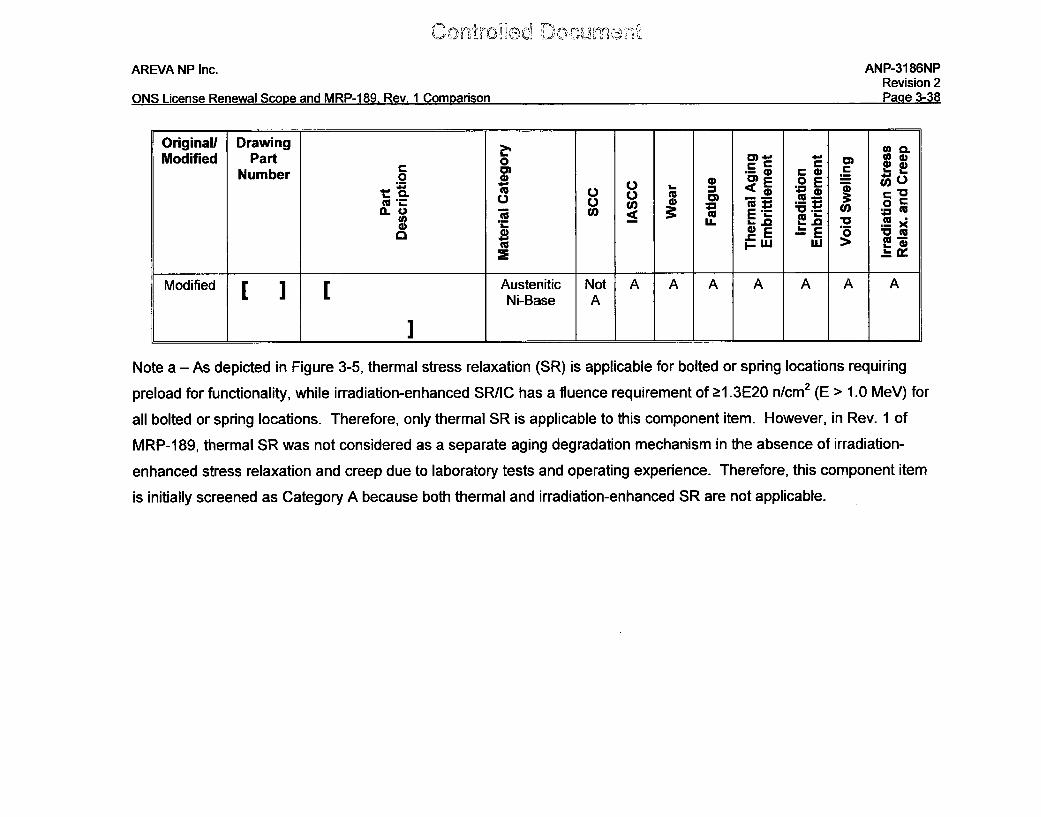
Original [1 [ Austenitic A A Not A A A A ASS A
Original [ ] r ] Austenitic A A Not A A A A ASS A
Original Austenitic A A A A A A A ANotea
PH SS
Original [ ] [ 1 Austenitic A A A A A A A ASS
Original Martensitic Not A A A Not A A A ASS A
Original [ ] [ ] Austenitic A A A A A A A ANotea
SS
Original [ ] [ ] Austenitic A A A A A A A ANotea
SS
Original Martensitic Not A A A Not A A A ASS A
Original [ ] Austenitic A A A A A A A ASS
, 'u m1naff Li 2 t
AREVA NP Inc.
ONS License Renewal Scone and MRP-1 89 Rev. 1 Comnarison
ANP-3186NPRevision 2Pane 3-37
Original/ Drawing WModified Part o Cam)• o 4)
Number 0o C E .2.
t® C u .F .m. "o .0_E .2) E( CUO)
cc LE M 20 - 0C
L J L Ni-Base A
Modified r rAustenitic Not A A A A A A A' J Ni-Base A
Modified [ ] r Austenitic A A A A A A A A
s.ss
Modified [ ] [] Austenitic Not A A A A A A ANotee
' 'PH Ni-Base AMoiid1 Austenitic Not A A A A A A A Note a
PH Ni-Base A
Modified [ 1 [ 1 Austenitic Not A A A A A A ANi-Base A
Modified [1 [ I Austenitic A A A A A A A AsS
Modified [ I Austenitic Not A A A A A A ANi-Base A
Modified [ ] [ ] Austenitic A A A A A A A A
SS
Con, aoýkad E"I"c;
AREVA NP Inc. ANP-3186NPRevision 2D~n d q'A.2%rkic 1; M 10 A RA00 4 On D 1 r, A
U.JI'I O u LI VLI•II [I VVIC1 tJ'.JU• aIIU IV11I---IUO. IcV. I IU.IIIUIIIOuII-
Original/ Drawing 0 C.
Modified Part o cmNumber o 0 a E OE
4--00 0) -- E U 0cc A
CL .2. -- cc= . .Q.LLU L_.0. E~f M MU
-G .E - E -o " c
Modified Austenitic Not A A A A A A ANi-Base A
Note a - As depicted in Figure 3-5, thermal stress relaxation (SR) is applicable for bolted or spring locations requiring
preload for functionality, while irradiation-enhanced SR/IC has a fluence requirement of >1.3E20 n/cm2 (E > 1.0 MeV) for
all bolted or spring locations. Therefore, only thermal SR is applicable to this component item. However, in Rev. 1 of
MRP-189, thermal SR was not considered as a separate aging degradation mechanism in the absence of irradiation-
enhanced stress relaxation and creep due to laboratory tests and operating experience. Therefore, this component item
is initially screened as Category A because both thermal and irradiation-enhanced SR are not applicable.
AREVA NP Inc. ANP-3186NPRevision 2
ONS License Renewal Scope and MRP-189, Rev. 1 Comparison Page 3-39
3.3.1.3 Failure Modes and Effects Criticality Analysis (FMECA)
The objective of the failure modes and effects criteria analysis (FMECA) is to provide a
systematic, qualitative review to identify components of RV internals component items
and age-related degradation mechanisms that potentially results in degradation leading
to significant risk. The FMECA is used to examine the susceptibility and safety and
economic consequences of identified RV internals components item/age-related
degradation mechanism combinations. The FMECA approach uses inductive reasoning
to ensure that the potential failure of each component item is analyzed, to determine the
results or effects thereof on the system, and to classify each potential failure mode
according to its severity.
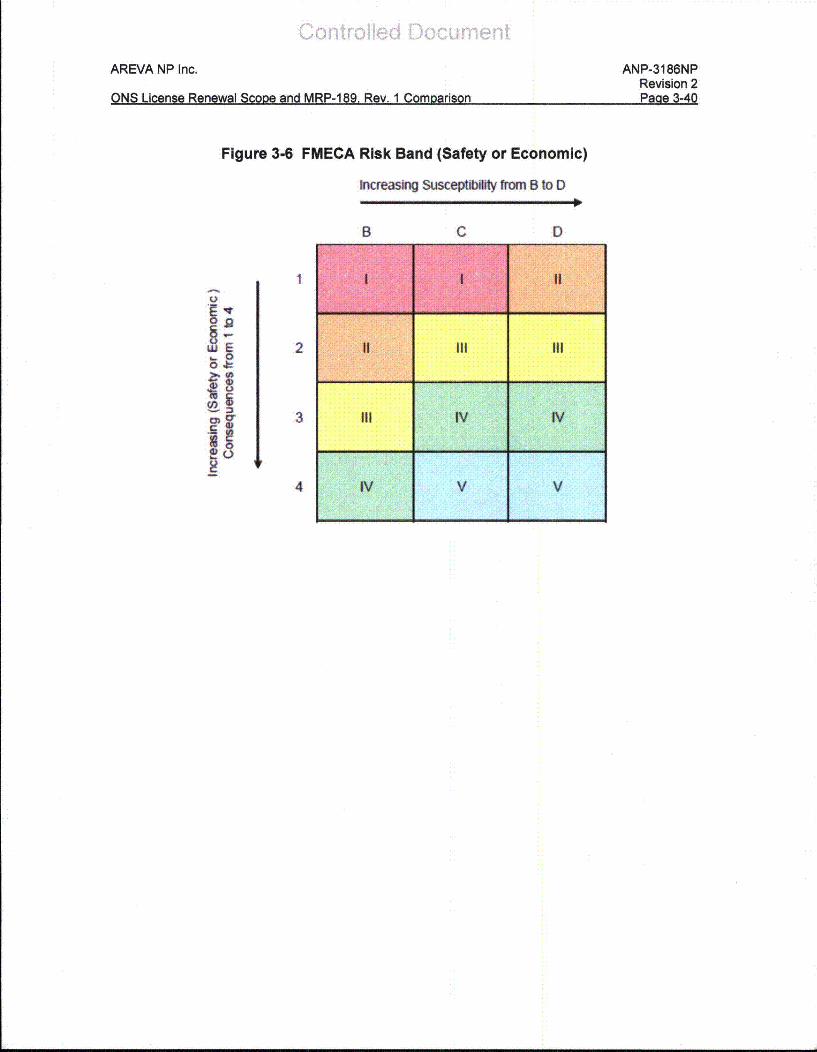
Each failure mode was judged on its importance to risk, based on the susceptibility and
severity of consequences. Consequences were examined from two perspectives:
safety and economic. A risk matrix was developed to correlate the consequence
severity of a particular age-related degradation mechanism with the susceptibility of that
particular mechanism. Different risk banks were used within the matrix to categorize the
level of risk of a particular component item/degradation mechanism pair, and provide
guidance on the strategies that should be developed to reduce the corresponding risk
and a basis for ranking and categorization.
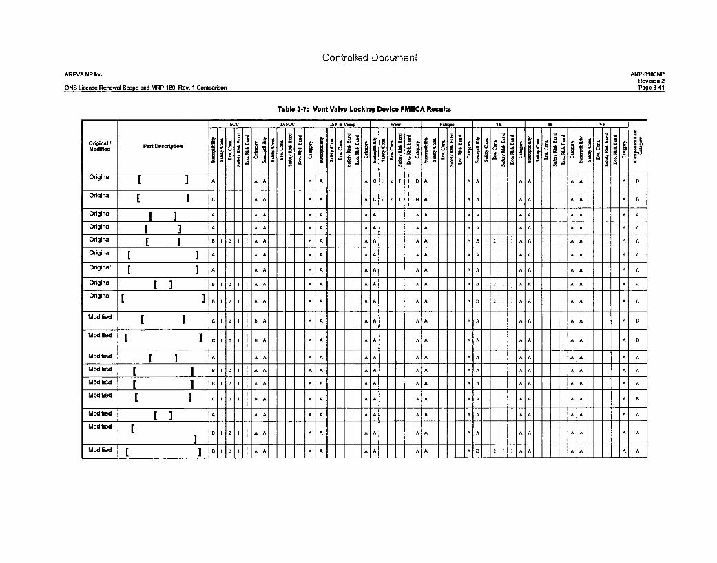
The risk matrix established for the development of MRP-227-A is shown in Figure 3-6 of
this report. The results of the FMECA are shown in Table 3-7.
AREVA NP Inc.
ONS License Renewal Stooe and MRP-18g. Rev. 1 Comnarison
ANP-3186NPRevision 2Paae 3-40
ONS License Renewal Scona and MRP-189 Rev. 1 Comnarison Paae 3-40
Figure 3-6 FMECA Risk Band (Safety or Economic)
Increasing Suscpt from B to D
B C D
0
g
0.o
1
2
3
4
III IV IV
IV I v V
Controlled Document
AREVA NP Inc.
ONS License Renewal Scope and MRP-189, Rev. 1 Comparison
ANP-3186NPRevision 2Page 3-41
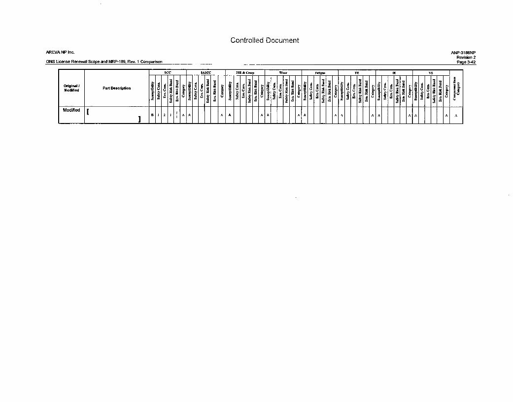
Table 3-7: Vent Valve Locking Device FMECA Results
-ASCC ISR & Crp We"r Ftige TE IE VS
Originall 1 atecio .1 t. A iU t. A J, o. dModified Pr D sc " " 2 3
Original CI A A A A A A C 211 B A A A A A A A A B
a ]
Original A A A A A A C A 2 1 B A A A A A A A A B
Original [ ] A A A A A AA A. A A A A A A A A
Original [ A A A A A A A A A A A A A A
Original [ j A A A A A A A A A A A AA A A A A
Original [ 2 A A A A A A AA A A A A A A A A
Original [ A 8121 A A A A AA A A AB A 21 A A A A A A
Original [ A 1 A AA A AA A AB 12 A A A A AOrg n lB 1 2 1 A A A A A A A A A B 1 2 I1 A A A A A A
Modified [ C 2 A A A A AA A AA A AA A A B
Modified [ ]C 1 2 B B A A A A A A A AA AA A A A B
Modified [ J A A A A A A A A A A A AA AA A A
Modified [ BI 2 1 A A A A A A A A A A A A A A A A
Modified [ 1 2 1 A AA A A A A AA A A A A A A A A
Modified [ C 2 IBAC 1 2 1 B A A A A A AA A A A A A B
Modified [ ] A A A A A A A A A A A A A A A A
Modified 1 2 1 AA A A A A A A A A A A A A A
Modified [ 1 ,•21 A A A A A AA AB 121 AA AA I A A
Controlled Document
AREVA NP Inc. ANP-3186NPRevision 2ONS License Renewal Scope and MRP-189, Rev. 1 Comparison Page 3-42
AREVA NP Inc. ANP-3186NPRevision 2
ONS License Renewal Scope and MRP-189, Rev. 1 Comparison Page 3-43
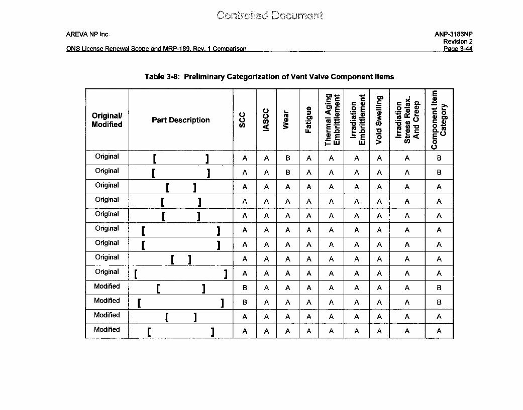
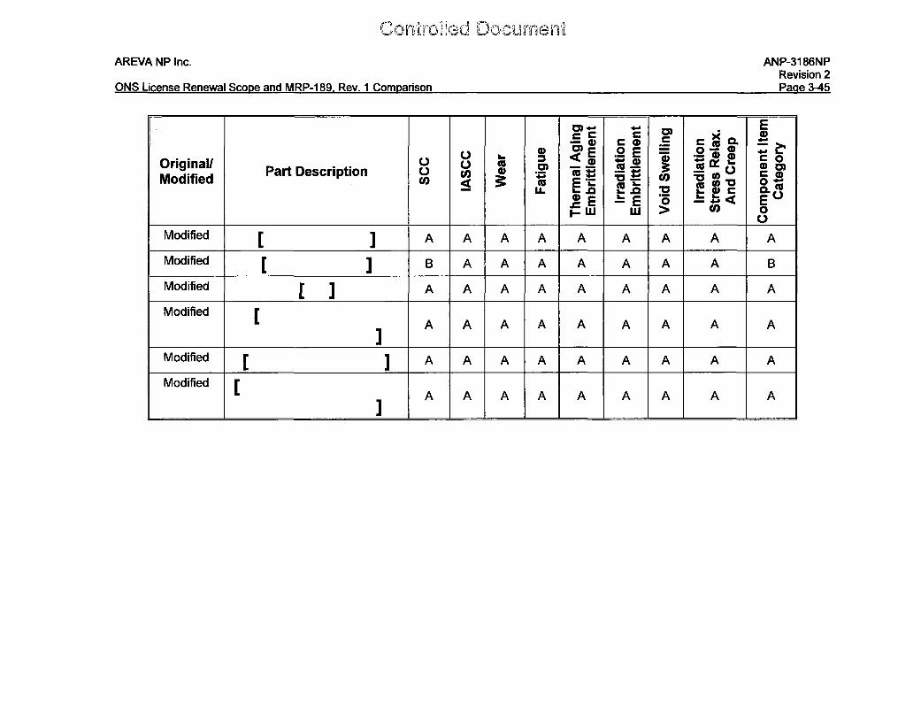
3.3.1.4 Categorization of Component Items
The categorization of component items uses the initial screening results (Section
3.3.1.2) and the FMECA results (Section 3.3.1.3) to separate the component items into
Category A, B, and C. Definitions of Categories A, B, and C and their respective criteria
are listed in Section 5 of MRP-189, Rev. 1. The results are shown in Table 3-8.
AREVA NP Inc.
ONS License Renewal Scone and MRP-1 89 Rev. 1 Comnarison
ANP-31 86NPRevision 2Di ~a L
Table 3-8: Preliminary Categorization of Vent Valve Component Items
CD, 0 CL0- 0
Original/ Part Description L) 0 - - .5 S'(•3 wModified U _ t. E ", 0 " ) -a U 0.1
.=E 'E 5 E<- IJ L > 0I 0
Original [ A A B A A A A A B
Original [ ] A A B A A A A A B
Original [ ] A A A A A A A A A
Original [ ] A A A A A A A A A
Original [ ] A A A A A A A A A
Original [ ] A A A A A A A A A
Original [ ] A A A A A A A A A
Original [ A A A A A A A A A
Original A A A A A A A A A
Modified [ ] B A A A A A A A B
Modified B A A A A A A A B
Modified A A A A A A A A A
Modified [ J A A A A A A A A A
AREVA NP Inc.
ONS License Renewal Scope and MRP-1 89. Rev. 1 ComDarison
ANP-3186NPRevision 2Paae 3-45
E) 0' E a .2 EO 0
OriginallU Pr ) wC )Part Description .) u) C = 9 0 - maModified '0 0
Sui > o)
Modified A A A A A A A A A
Modified J B A A A A A A A B
Modified [ ] A A A A A A A A A
Modified [
Modified [ A A A A A A A A A
Modified [A A A A A A A A A
Conrdid oumnAREVA NP Inc. ANP-3186NP
Revision 2ONS License Renewal Scope and MRP-189, Rev. 1 Comparison Page 3-46
3.3.1.5 Engineering Evaluation and Assessment and Categorization for
Inspection
The component items screened as non-Category A component items in Table 3-8 are
as follows:
a Original vent valve locking device: [ ] for wear
Wear between the [ ] was the driving factor for the
initial replacement of the original vent valves near the outlet nozzle locations (see
Section 3.3.1). During video inspections of the valves in the late 1970s, damage to the
original vent valves was seen [
I Since the cause of the
damage was determined to be from the vent valves within close proximity to the outlet
nozzles due to the high flow in those locations and FCAs for the ONS units indicate that
the four original vent valves on either side of the two outlet nozzles be replaced with the
modified vent valves, [
I
(Co otrdicd Dcumnoai"AREVA NP Inc. ANP-3186NP
Revision 2ONS License Renewal Scope and MRP-189, Rev. 1 Comparison Page 3-47
As seen in Figure 3-1 and Figure 3-2 of this report, the [
] have limited accessibility or inspection. The function of the jackscrew is to
[
] The retaining rings are considered primary component
items within the MRP-227 program at the ONS units and are to be inspected via visual
VT-3 inspection on the 10-year ISI interval. If the function of the [
I were degraded during service, the visual inspection of the [
] in the vicinity of these component items, would indicate that the [
had turned and was out of design position. The observation that the [ I is
not damaged and the confirmation that the [ ] is in the design configuration
is verification that the locking devices are acceptable.
Controfle DocumentAREVA NP Inc. ANP-3186NP
Revision 2Paae 3-48ONS License Renewal Scooe and MRP-189. Rev. 1 Comoarison
Additionally, the ONS units perform a visual inspection each refueling outage and a VT-
3 inspection during the 10-year ASME B&PV Code inservice inspection (ISI) intervals of
the vent valves. The accessible surfaces of the vent valves are visually inspected,
including the locking devices. [x] Previously, this wear damage to the original vent
valves was also detected via visual inspection. For these reasons, the original vent
valve locking device [ ] are further categorized as
"No Additional Measures" for the ONS units. [
I
Modified vent valve locking device: [] for PWSCC
CurrlroHec,)] Docurncýn,
AREVA NP Inc. ANP-3186NPRevision 2
ONS License Renewal Scope and MRP-189, Rev. 1 Comparison Page 3-49
The modified vent valve items that are fabricated from Alloy 600 and potentially
susceptible to PWSCC are the [
] As noted above, the ONS units perform a visual inspection each
refueling outage and a VT-3 inspection during the 10-year ASME B&PV Code ISI
intervals of the vent valves. The accessible surfaces of the vent valves are visually
inspected, including the locking devices. [x] [
] Observation of damage is a relevant indication and requires disposition
or correction.
ConitrodUed Documenf,
AREVA NP Inc.
ONS License Renewal Scone and MRP-189. Rev. 1 Comnarison
ANP-3186NPRevision 2Paae 3-50
As seen in Figure 3-3 and Figure 3-4 of this report, the [
I are accessible for inspection.
The [ ] are located on the [
] The retaining rings are considered
primary component items within the MRP-227 program at the ONS units and are to be
inspected via visual VT-3 inspection on the 10-year IS1 interval. If the function of the
I I were degraded during service, the
visual inspection of the [ 1 in the vicinity of these component items,
would indicate that the [ I
Therefore, it is likely that the visual inspection performed during each refueling outage
as well as the VT-3 visual inspection of the vent valve retaining rings performed on the
10-year ISI interval would detect the [ ] indicating potential cracking
or damage to the [ I
Additionally, a previous inspection at a B&W unit (see Section 3.3.1) identified cracking
of [ ] For
these reasons, the modified vent valve locking device [
] are further categorized as "No Additional Measures" for the
ONS units.
C.ontroed Oc~cumeritAREVA NP Inc. ANP-3186NP
Revision 2ONS License Renewal Scope and MRP-189, Rev. 1 Comparison Page 3-51
However, it is noted that in MRP-227-A the existing program in place for vent valve
locking device aging management at ONS is not identified as such in Table 4-7 (of
MRP-227-A). Duke is working with the MRP to establish interim guidance to account for
this discrepancy and incorporate the appropriate information in the next revision of
MRP-227. Therefore, in this document, ONS assumes that the visual inspections
currently performed are equivalent to an Existing Program for MRP-227 implementation.
3.3.2 Remnants of the SSHTs
Section 3.2 of this report identified that remnants of the original SSHTs were omitted
from MvIRP-189, Rev. 1 and were contained in the LR scope for the ONS RV internals.
As such, these component items are subject to aging management review.
SSHT Assembly Background
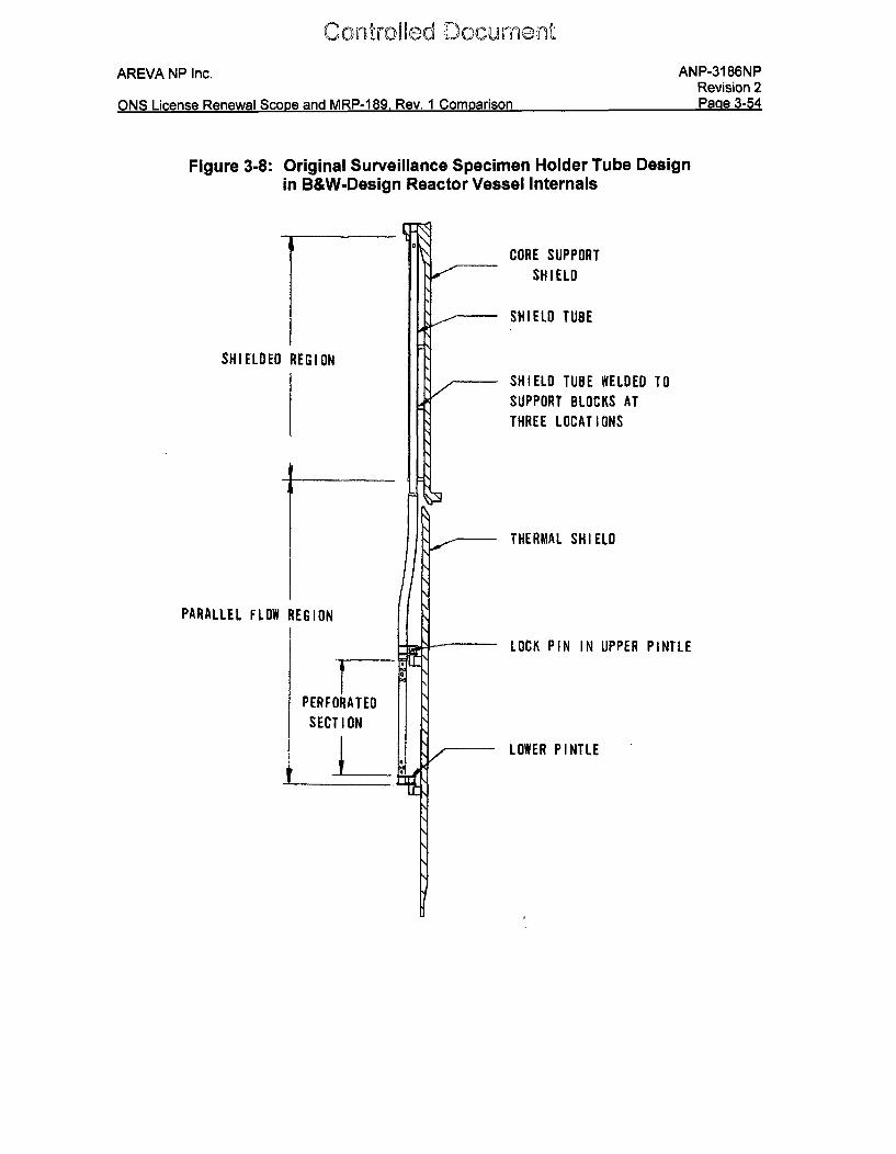
The original design of the B&W 177-fuel assembly class reactors included three reactor
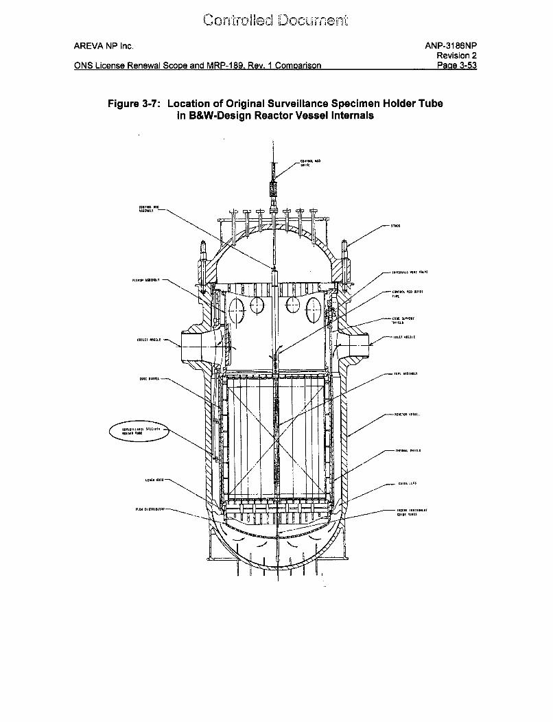
vessel SSHTs located near the reactor vessel inside wall, as shown in Figure 3-7 and
Figure 3-8. Each of the tubes was designed to hold two capsules containing reactor
vessel surveillance specimens. In 1976, the SSHTs in a number of the B&W units were
found to be damaged. Subsequently, all operating B&W units were shut down for
inspection of the holder tubes. This inspection revealed that all of the SSHTs had been
damaged to some extent. To prevent further damage and to eliminate the possibility of
overall system damage if parts of the holder tube were dislodged, all of the surveillance
capsules and holder tubes that had either failed or were of the same design were
removed from the vessels. Units involved include ONS-1, ONS-2, and ONS-3. [xi]
However, remnants of the original assemblies still remain attached to the RV internals.
Conto~d DocurneNAREVA NP Inc. ANP-3186NP
Revision 2ONS License Renewal Scope and MRP-1 89, Rev. 1 Comparison Page 3-52
Materials of Construction
There are two portions of the SSHT assemblies that remain affixed to the RV internals
at ONS-1, ONS-2, and ONS-3. The [ ]was left intact and is attached to the CSS assembly. The majority of the lower portion of
the SSHT assembly was removed and the only remaining portions consist of the [
] The general materials of
construction for the remaining portions of the SSHT assemblies are identified in the
original bill of materials drawings and listed below in Table 3-9 of this report.
AREVA NP Inc. ANP-3186NPRevision 2P2 ia A-,,AMKJ I it-one PanlavAIo -I- a~Y ~nnV iAPPD.A0 Maw 1~i I'n C nri-nn
Figure 3-7: Location of Original Surveillance Specimen Holder Tubein B&W-Design Reactor Vessel Internals
flIT VAfLW
(Contoed Dcocur-nnt
AREVA NP Inc.
ONS [icense Renewal Scone and MRP-1 89. Rev. 1 Comparison
ANP-3186NPRevision 2Paae 3-54
ONS License Renewal Scone and MRP-189 Rev. 1 Comnarison
Figure 3-8: Original Surveillance Specimen Holder Tube Designin B&W-Design Reactor Vessel Internals
9,
SHIELDED REGION
PARALLEL FLOW REGION1PERFORATEDSECTION
CORE SUPPORTSHIELD
SHIELD TUBE
/
SHIELD TUBE WELDED TOSUPPORT BLOCKS AT
THREE LOCATIONS
THERMAL SHIELD
LOCK PIN IN UPPER PINTLE
LOWER PINTLE
C o,'roWad Doc umcnt
AREVA NP Inc. ANP-3186NPRevision 2
ONS License Renewal Scooe and MRP-189, Rev. 1 Comparison Page 3-55
Table 3-9: SSHT Assembly Remnant Materials of Construction
Controfled Docu. nt
AREVA NP Inc. ANP-3186NPRevision 2po a 2A-,;r~]QI it-amea Pflanawol-QI men onri KAPPD PC) Paw, 1 Cnm riae~n
W te 0
Con'iro~d Dlocumnanfl'
AREVA NP Inc.
ONS License Renewal Scone and MRP-1 89. Rev. 1 Comoarison
ANP-3186NPRevision 2Paae 3-57
Note a - All stainless steel welds assumed to be either Type 308 or 308L material, in
accordance with standard industry practice at the time of fabrication.
Note b - The Ni-base alloy weld material is assumed to be Alloy 69, Alloy 82, or Alloy
182 material, in accordance with standard industry practice at the time of fabrication.

C~nn-ýrcnkd DoumentAREVA NP Inc. ANP-3186NP
Revision 2Pgna a ~r;t'KQI iýn& DiflnlAini Qr in, nnqADCUR1O Pa 1 rnm ariann
3.3.2.1 Identification of Screening Parameters and Criteria
The screening parameters for the component items listed in Table 3-9 are tabulated in
Table 3-10. The environmental parameters for the component items listed in Table 3-9
of this report are [
I
AREVA NP Inc. ANP-3186NPRevision 2Da= 'LAOQAM5~ I ir~an~n P~n~ui±~iI 5~rnn~ 2nr4 MRP...1 RO Pn~, '1 Cnmr~rienn
r)M-CZ 1 iranca PanaurA -Qf-n a tanti RAPP-1 RQ Pow 1 rnm riann On a go
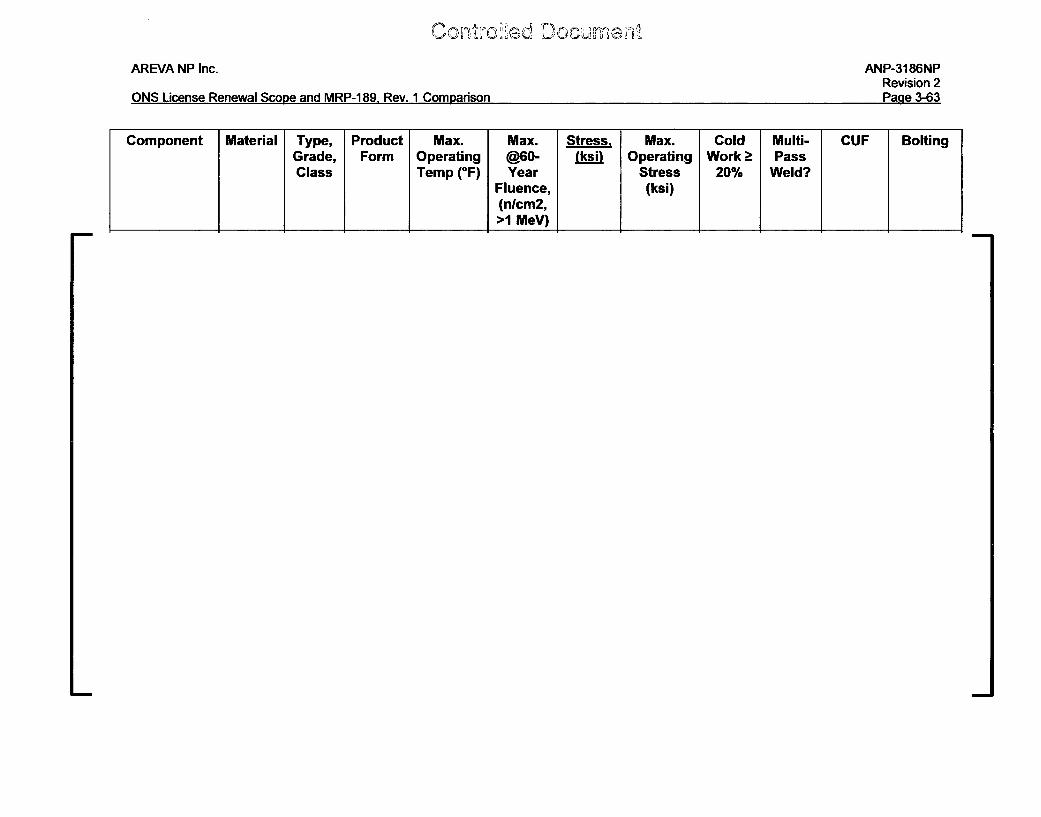
Table 3-10: SSHT Assembly Remnant Screening Parameters
Component Material Type, Product Max. Max. Stress, Max. Cold Multi- CUF BoltingGrade, Form Operating @60- (ksi) Operating Work > PassClass Temp (OF) Year Stress 20% Weld?
Fluence, (ksi)(nlcm2,>1 MeV)
AREVA NP Inc. ANP-3186NPRevision 2
OM5~ I irpn~p P~n~w~I 5~rnn~ ~nd MRP-1 R~ R~u I Cnmn~ri~nn
Component Material Type, Product Max. Max. Stress, Max. Cold Multi- CUF BoltingGrade, Form Operating @60- (ksi) Operating Work > PassClass Temp (OF) Year Stress 20% Weld?
Fluence, (ksi)(nlcm2,>1 MeV)
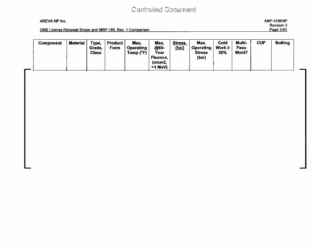
AREVA NP Inc. ANP-3186NPRevision 2On ýq-9flUKC 1 ; D fflAfI Cnn~ An, RADD- I 0 1 t- Ar~j.,LIU uý,L cya,.t ýu ca" I~ flx -Iw., . I iiv tý.,o %I IO4~
Component Material Type, Product Max. Max. Stress, Max. Cold Multi- CUF BoltingGrade, Form Operating @60- (ksi) Operating Work > PassClass Temp (*F) Year Stress 20% Weld?
Fluence, (ksi)(nlcm2,>1 MeV)
C co)
AREVA NP Inc. ANP-3186NPRevision 2Page 3-62ONS License Renewal Scope and MRP-1 89, Rev. 1 Comparison
Component Material Type, Product Max. Max. Stress, Max. Cold Multi- CUF BoltingGrade, Form Operating @60- (ksi) Operating Work > PassClass Temp (OF) Year Stress 20% Weld?
Fluence, (ksi)(nlcm2,>1 MeV)
AREVA NP Inc. ANP-3186NPRevision 2
2ný LA'nflMQ I irýone 0--ai~ C-nn -n4 RADD-1 R0 Ooý 1 flnmnonre~n.W.- X'. L.%II.I4IfO JAI~ IIlI~l O V IS~* M OIO~ %l
Component Material Type, Product Max. Max. Stress, Max. Cold Multi- CUF BoltingGrade, Form Operating @60- (ksi) Operating Work > PassClass Temp (*F) Year Stress 20% Weld?
Fluence, (ksi)(nlcm2,>1 MeV)
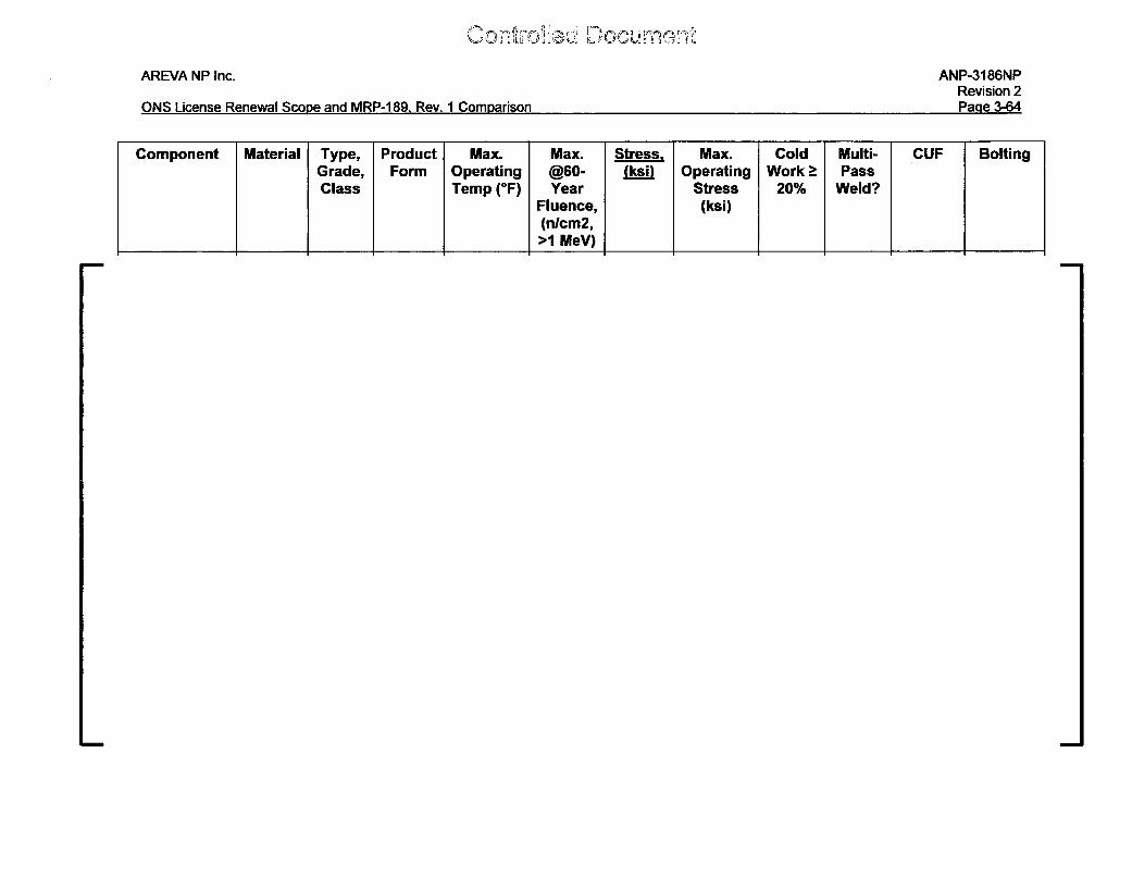
ý..y r''ý rý Jý , "Dý' 0 'ý' L' U
AREVA NP Inc. ANP-3186NPRevision 2P~Inp -C~N~ I irpn~p P~n~w~I 5~rnnp ~nrI MRP-1 R~I R~u I flnmn~ari~nn
ONS License Renewal Scone and MRP-1 89 Rev 1 Comparison Pane 3-64
Component Material Type, Product Max. Max. Stress, Max. Cold Multi- CUF BoltingGrade, Form Operating @60- (ksiU Operating Work > PassClass Temp (OF) Year Stress 20% Weld?
Fluence, (ksi)(nlcm2,>1 MeV)
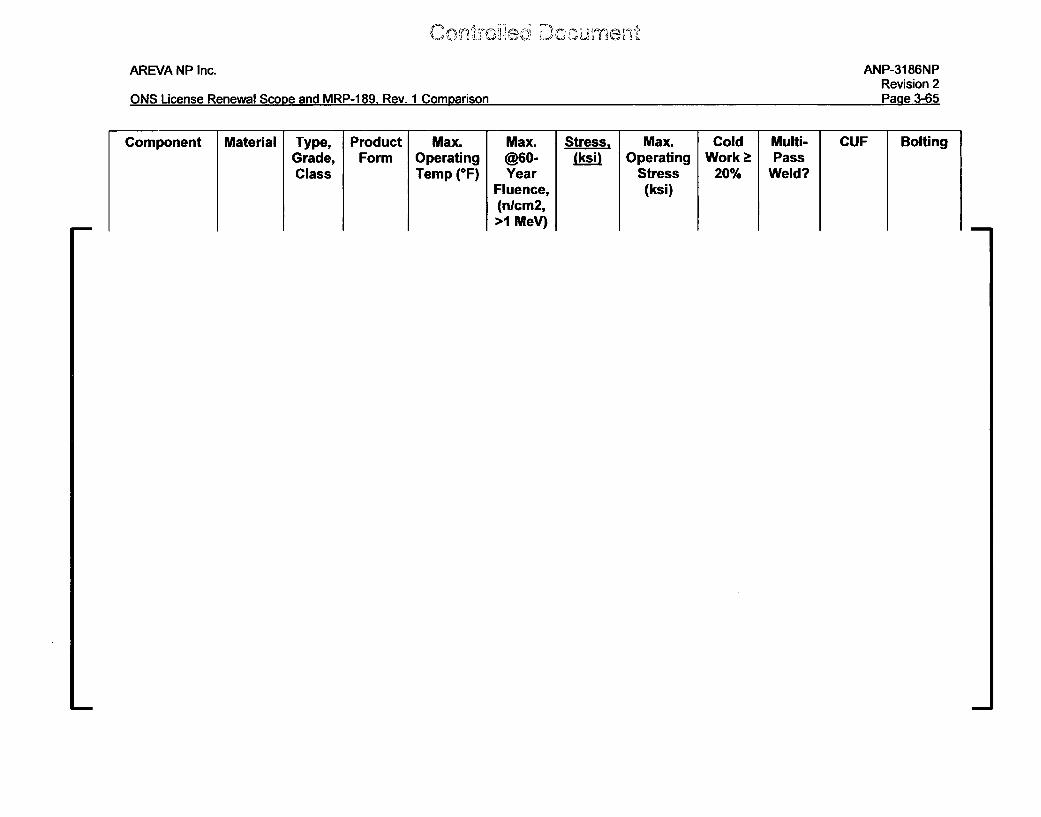
AREVA NP Inc.
ONS License Renewal Scope and MRP-1 89, Rev. 1 Comparison
ANP-3186NPRevision 2P~nnP .'-R RPane 3-65
Component I Material Type,Grade,Class
ProductForm
Max.OperatingTemp (OF)
Max.@60-Year
Fluence,(nlcm2,>1 MeV)
Strss, Max.Operating
Stress(ksi)
ColdWork >
20%
Multi-Pass
Weld?
CUF Bolting
Conmud~jsc Docv-aaLAREVA NP Inc. ANP-3186NP
Revision 2ONS License Renewal Scope and MRP-189, Rev. 1 Comparison Page 3-66
3.3.2.2 Characterize and Screen for Degradation
The SSHT assembly remaining items for the three ONS units identified in Table 3-9 of
this report need to be screened using the screening process and criteria that has been
used for other RV Internals component items and documented in MRP-189, Rev. 1.
The screening criteria are provided in this report as Figure 3-5. Each age-related
degradation mechanism is screened for each PWR internals component item by
comparing the values in Table 3-10 against the screening criteria in Figure 3-5 and the
results are contained in Table 3-11 of this report. An aging mechanism is screened in if
the screening criteria are met or exceeded for that component item. Otherwise, the
aging mechanism is screened out for the component item. If a value is unknown (e.g.,
operating stress), it is assumed to have exceeded the applicable screening criteria
(unless otherwise noted).
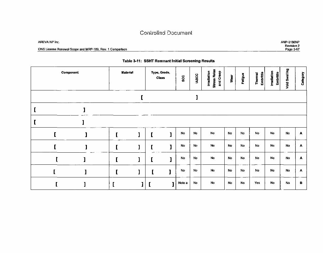
Con-irolled DocumentAREVA NP Inc. ANP-3186NP
Revision 2ONS License Renewal Scope and MRP-189, Rev. 1 Comparison Page 3-67
Table 3-11: SSHT Remnant Initial Screening Results
Component Material Type, Grade, C C o0
Class V9 42 eO 0*Co o e • 8
i) EaE
I>
I.I
I
I
L
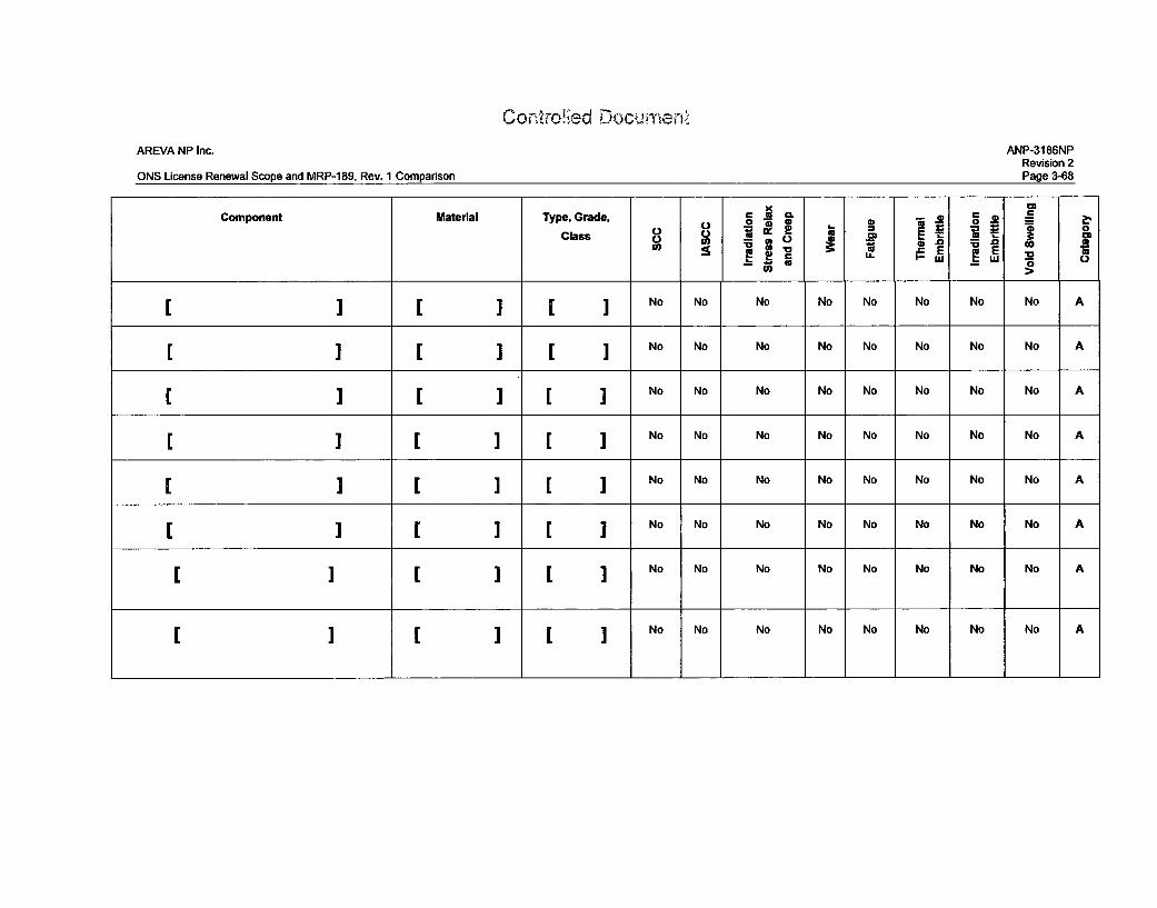
AREVA NP Inc.
ONS License Renewal Scope and MRP-189, Rev. 1 Comparison
Contro!ted Docum•e...ANP-3186NP
Revision 2Page 3-68
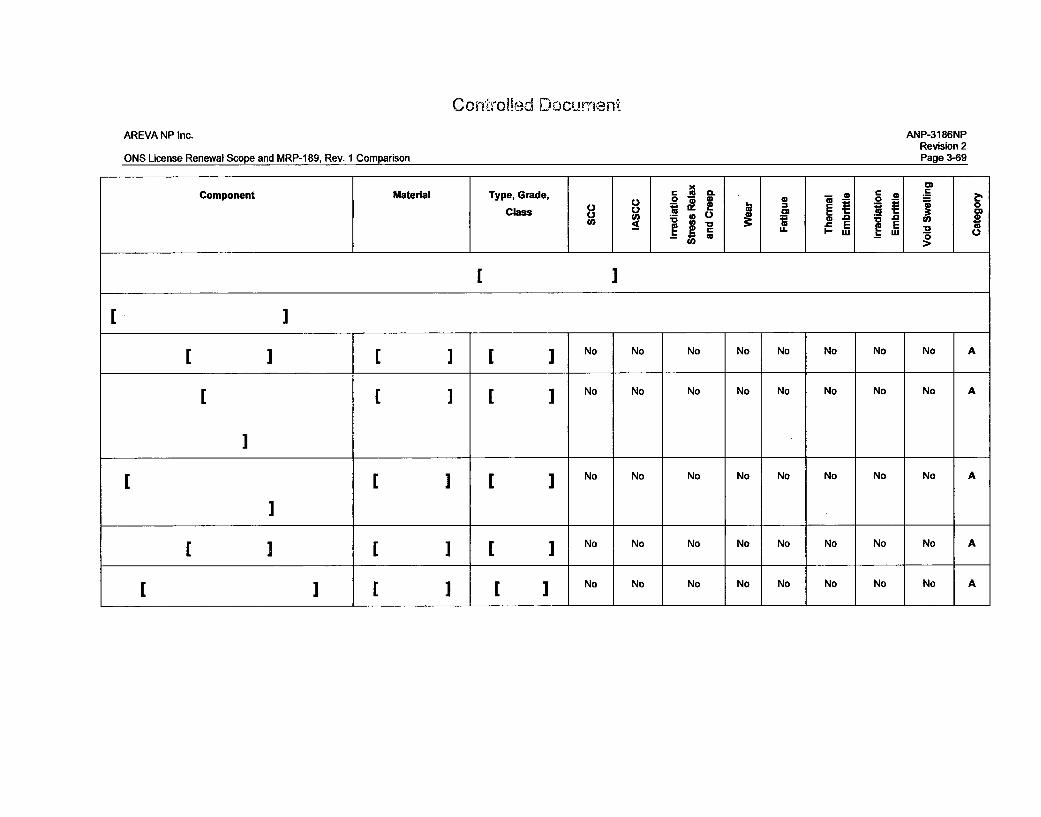
Cont'roed Documen-'
AREVA NP Inc. ANP-3186NPRevision 2
ONS License Renewal Scope and MRP-1 89, Rev. 1 Comparison Page 3-69o-DComponent Material Type, Grade, - e= 10 E
I U i o
[Class V ._______I_____ M_ _
_ _ _ _ _ _ _ _ _ _~~~~L E__ _ _ E___ _.~ _ _ _ _ _ _ _ _
fuIJ u
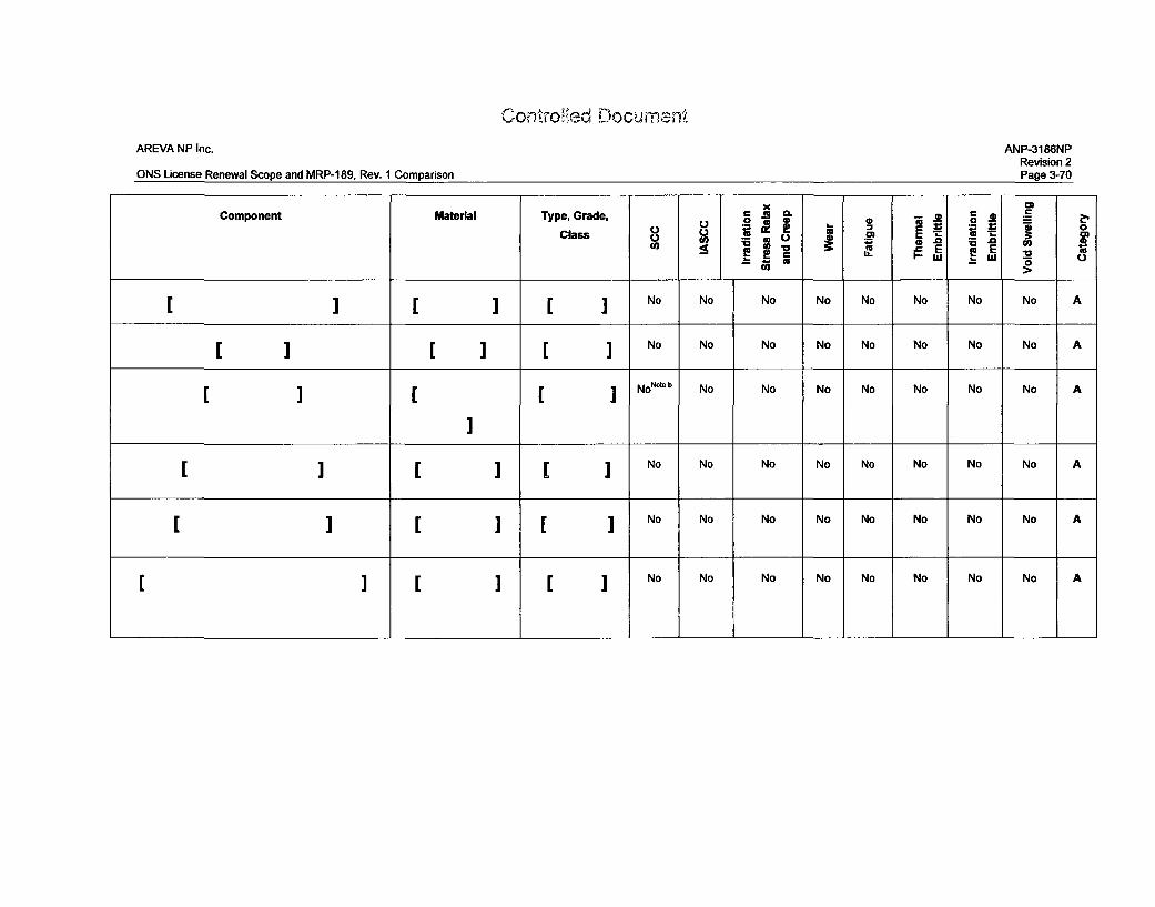
Contro~ed DocumrnenK
AREVA NP Inc.
ONS License Renewal Scope and MRP-189, Rev. 1 Comparison
ANP-3186NPRevision 2Page 3-70
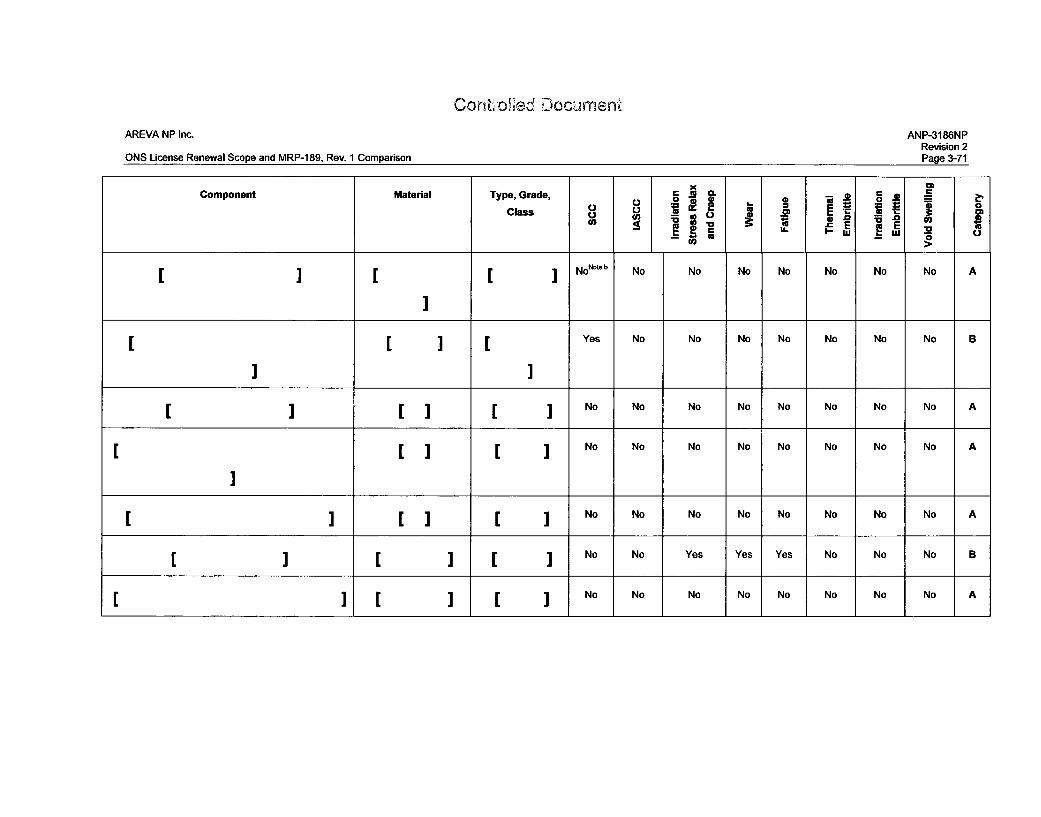
Conltf Oe`ed DocumentAREVA NP Inc. ANP-3186NP
Revision 2ONS License Renewal Scope and MRP-1 89, Rev. I Comparison Page 3-71
Controlled Docume'.
AREVA NP Inc. ANP-3186NPRevision 2
ONS License Renewal Scope and MRP-189, Rev. 1 Comparison Page 3-72
Note a - Although it is currently unknown whether this item is susceptible to thermal embrittlement and SCC (i.e., no records search for the actual heat
treatment condition has been performed at this time), SCC is very unlikely because there are no stresses on this item once the surveillance specimen holder
tubes were removed.
Note b - Although the stress is assumed to be < 30 ksi, it is not expected that any stress on this item will be beyond the screening criterion provided as Figure
3-4 of this document.
Controled Docuiment
AREVA NP Inc. ANP-3186NPRevision 2
ONS License Renewal Scope and MRP-189, Rev. 1 Comparison Page 3-73
3.3.2.3 Failure Modes and Effects Criticality Analysis (FMECA)
The objective of the failure modes and effects criteria analysis (FMECA) is to provide a
systematic, qualitative review to identify components of RV internals component items
and age-related degradation mechanisms that potentially results in degradation leading
to significant risk. The FMECA is used to examine the susceptibility and safety and
economic consequences of identified RV internals components item/age-related
degradation mechanism combinations. The FMECA approach uses inductive reasoning
to ensure that the potential failure of each component item is analyzed, to determine the
results or effects thereof on the system, and to classify each potential failure mode
according to its severity.
Each failure mode was judged on its importance to risk, based on the susceptibility and
severity of consequences. Consequences were examined from two perspectives:
safety and economic. A risk matrix was developed to correlate the consequence
severity of a particular age-related degradation mechanism with the susceptibility of that
particular mechanism. Different risk banks were used within the matrix to categorize the
level of risk of a particular component item/degradation mechanism pair, and provide
guidance on the strategies that should be developed to reduce the corresponding risk
and a basis for ranking and categorization.
The risk matrix established for the development of MRP-227-A is shown in Figure 3-6 of
this report. The results of the FMECA for the SSHT remnant items are shown in Table
3-12.
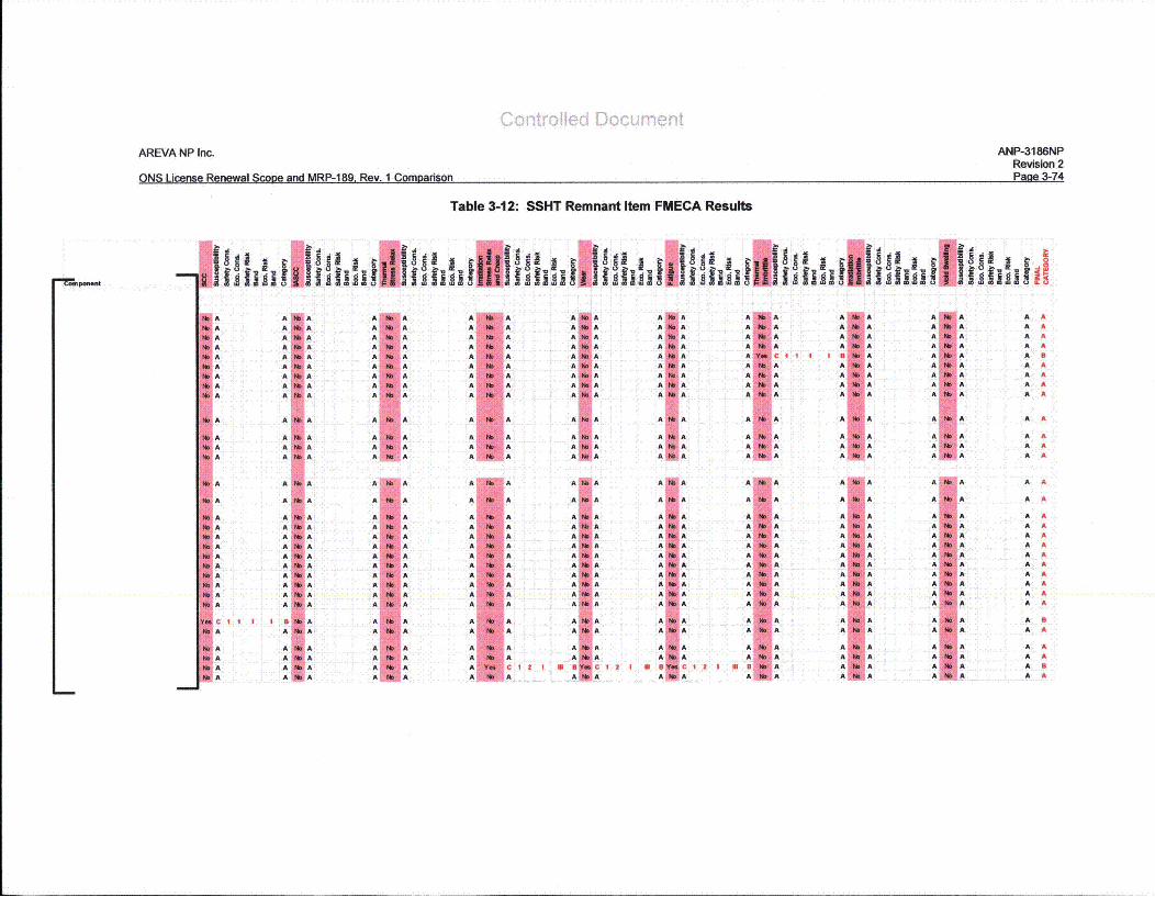
AREVA NP Inc.
ONS License Renewal Scooe and MRP-189, Rev. 1 Comparison
ANP-3186NPRevision 2PAn• 2°•7A
Pa 3-74
Table 3-12: SSHT Remnant Item FMECA Results
f Ihl fil fill E8* ,AAAAAAAAA
A
AAA
AAAAAAAAA
A
AAA
A
A
AAAAAA
AAA
A
A
AAAA
A
A
AAAAA
AAAAA
A
AAA
AI
A AA AA AA AA AA AA AA AA A
A A
A AA AA A
A A
A A
A AA AA AA AA AA AA AA AA AA A
A AA A
A AA AA AA A
I A Af A AI A Af A AA A AA A A4 A Ak A Ak A A
k A A
k A AA A A
A A A
SAMA
SA A
11 A AA1 A AAt A A
11 A ASA A
A A ASA ASA ASA A
Ak A A
A. A AAt A A
11 A AA A
K AIA
A AA AA AA AA AA AA AA AA A
A A
A AA AA A
A A
A A
A AA AA AA AA AA AA AA AA AA A
A AA A
A AA A
8 cAIA
A AA A
A AA AA CAIA AA AA AA A
A A
A AA AA A
A A
A AA AA AA AA A
AA AA AA AA A
A AA A
A AA A
1 21 EB A
AIA
A AA AA AA AB AA A
A AA AA A
A A
A AA AA A
A A
A A
A AA AA AA AA AA AA AA AA AA A
A AA AA A
A AA AA A
A AA AA AA AA AA AA AA AA A
A A
A AA AA A
A A
A A
A AA AA AA AA AA AA AA A
A AA A
A AA A
A AA AA AA A
Co r,1old Documemn
AREVA NP Inc. ANP-3186NPRevision 2
ONS License Renewal Scope and MRP-189, Rev. 1 Comparison Page 3-75
3.3.2.4 Categorization of Component Items
The categorization of component items uses the initial screening results (Section
3.3.2.2) and the FMECA results (Section 3.3.2.3) to separate the component items into
Category A, B, and C. Definitions of Categories A, B, and C and their respective criteria
are listed in Section 5 of MRP-189, Rev. 1. The results are shown in Table 3-13.
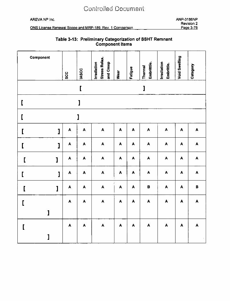
Conrfed DO'C~rentAREVA NP Inc.
ONS License Renewal Scove and MRP-189, Rev. 1 Comparison
ANP-3186NPRevision 2Paae 3-76
Table 3-13: Preliminary Categorization of SSHT RemnantComponent Items
Component )4
u, 5 .. Cli u. I-L U > U
= ]C UQ 2
A A A A A A A A A
A A A A A A A A A
A A A A A A A A A
A A A A A A A A A
A A A A A B A A B
A A A A A A A A A
A A A A A A A A A
A]
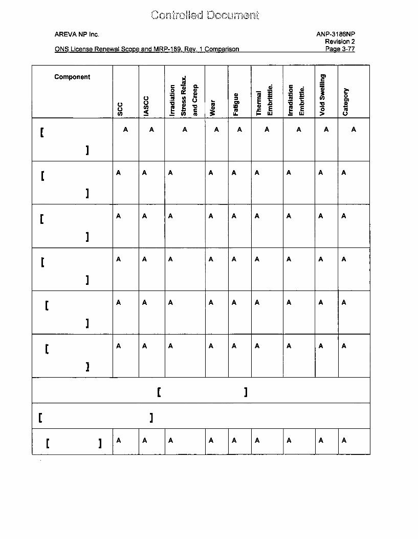
on''r(rCla DOCUMMENrýAREVA NP Inc. ANP-3186NP
Revision 2Ona m .A77n I i~naDmun Qv in onn RA~DD-1 Paw ~ 1 f~enm nria,~n
Component A
S 0200co oa LL w w > o
A A A A A A A A A
A A A A A A A A A
A A A A A A A A A
A A A A A A A A A
A A A A A A A A A
A A A A A A A A A
A'1 A A A A A A A A A
L I
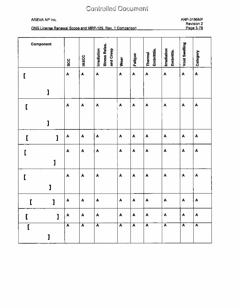
IConlý'o~s1 DocumentAREVA NP Inc. ANP-3186NP
Revision 2Paae 3-78
vONS Lic ns ........... .. Scon .... .... . i .. .. ... Rev ..... 1 Co p rio..a 37
Component A CD
= a! 0
A A A A A A A A A
[A A A A A A A A A
A A A A A A A A A
A A A A A A A A A
A A A A A A A A A
A A A A A A A A A
r A A A A A A A A A
A A A A A A A A A[A A A A A A A A A
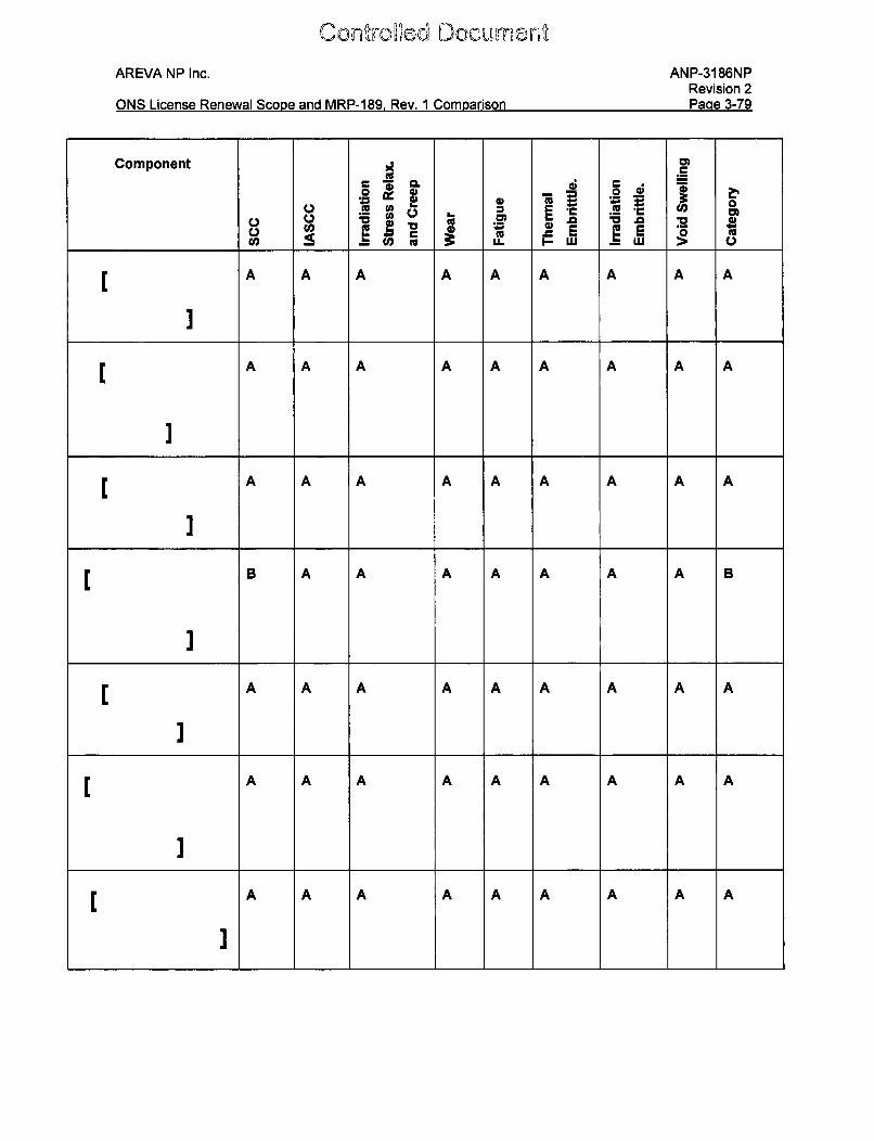
[Donro~d~ DocumentAREVA NP Inc. ANP-3186NP
Revision 2D•o _ Q 70f^K10 I ,; D I Q AADD 100 D~ 1 tN
%.I~ I.CHO WH VV F'%Iivyi .JbAJI ca" U IVI V ~ V. I 11ea OWH.J I ILG -U
Component A
CL ; r- 4;0
A A A AA A A AM . V 0 V
U ~' E ~E Z c]a M _ _ I. Lu > 1
A A A A A A A A A
A A A A A A A A A
]
A A A A A A A A A
IIA A A A A A A A A
AA A A A A A A A A
[A A A A A A A A A
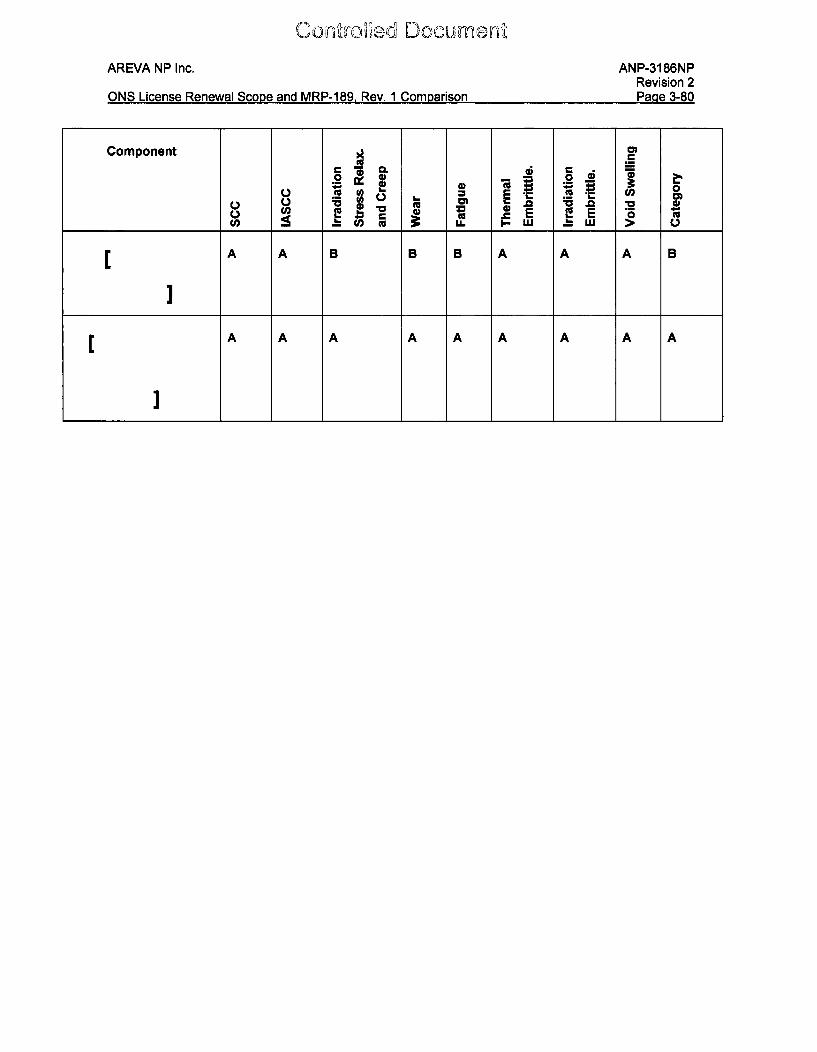
oc1~ Doct~m~"AREVA NP Inc. ANP-3186NP
Revision 2Paae 3-80ONS License Renewal Scooe and MRP-189, Rev. 1 Comparison
Component A
u u tM Vk Icc 0.
V___ _ __ w_ h w >
A A B B B A A A B
A A A A A A A A A
Con',ixokd DcGumeni
AREVA NP Inc. ANP-3186NPRevision 2
ONS License Renewal Scope and MRP-189, Rev. 1 Comparison Page 3-81
3.3.2.5 Engineering Evaluation and Assessment and Categorization for
Inspection
The component items screened as non-Category A component items in Table 3-13 are
as follows:
Con~rofd DcumbentAREVA NP Inc. ANP-3186NP
Revision 2Pnrre 3-82
As described in the inspection plan for the ONS units RV Internals [x], the remaining
remnants of the SSHT structures are a part of the typical core support structures that
will receive a VT-3 examination during the fourth and future 10-year inservice-inspection
(ISI) internals at ONS.
As noted above, these items currently serve no function and should cracking initiate the
worst scenario that could occur is that the item (or a piece of the item) could become a
loose part. [
Therefore the SSHT [ I assembly component items [
I are categorized as "No Additional Measures" for the ONS units
and no augmented examinations are required.
AREVA NP Inc. ANP-3186NPRevision 2
ONS License Renewal Scope and MRP-189, Rev. 1 Comparison Page 4-1
4.0 CONCLUSIONS
As required by applicant/licensee action item #2 for the MRP-227-A SER, a comparison
was made between Table 4-1 and 4-2 in MRP-189, Rev. 1 and the component items
designated in the scope of license renewal for the ONS units. Once this comparison
was made, three component items were identified as being within the scope, but not in
the applicable MRP-189, Rev. 1 tables. These components items are as follows:
1. Vent Valve Misc. Locking Device Parts (original)
2. Vent Valve Misc. Locking Device Parts (modified)
3. Remnants of the SSHTs
A review of background information pertaining to the vent valve locking devices, both
original and modified, and the remnants of the SSHTs was made. The appropriate
drawings and the items of interest were identified. The MRP-227-A sequence steps
were used to propose any necessary modifications to the program defined in MRP-227,
as modified by the SER. The material types as well as screening parameters such as
temperature, fluence, neutron exposure, and operating stresses were identified. These
parameters were then used to compare to the screening criteria from MRP-1 89, Rev. 1
to perform the initial screening of these items for degradation. A failure modes and
effects criticality assessment (FMECA) was performed and a preliminary categorization,
using the degradation screening results as well as the FMECA was performed. Finally,
an engineering evaluation and assessment was used to categorize the component
items for inspection.
The results are as follows:
1. Vent Valve Misc. Locking Device Parts (original) - Categorized as "Category A"or "No Additional Measures"
2. Vent Valve Misc. Locking Device Parts (modified) - Categorized as "Category A"or "No Additional Measures"
3. Remnants of the SSHTs - Categorized as "No Additional Measures"
C 0 nrll rec a D c c um on ý'AREVA NP Inc. ANP-3186NP
Revision 2PAOa 4-2
ONS License Renewal Scone and IVIRP-1 89 Rev 1 Comparison Pane 4-2
I
However, it is noted that in MRP-227-A the existing program in place for vent valve
locking device aging management at ONS is not identified as such in Table 4-7 (of
MRP-227-A). Duke is working with the MRP to establish interim guidance to account for
this discrepancy and incorporate the appropriate information into the next revision of
MRP-227. In this document, ONS assumes that the visual inspections currently
performed are equivalent to an Existing Program for MRP-227 implementation.
As described in the inspection plan for the ONS units RV Internals [x], the remaining
remnants of the SSHT structures are a part of the typical core support structures that
will receive a VT-3 examination during the fourth and future 10-year inservice-inspection
(ISI) internals at ONS.
These items currently serve no function and should cracking initiate the worst scenario
that could occur is that the item (or a piece of the item) could become a loose part.
Therefore the remaining SSHT [
I are categorized as "No Additional Measures" for the
ONS units and no augmented examinations are required.
DCUM -. m.t
AREVA NP Inc. ANP-3186NPRevision 2
ONS License Renewal Scope and MRP-189, Rev. 1 Comparison Page 4-3
Additionally, during a previous records search, a feature unique to ONS-1 was identified
for the plenum cover weldment rib pads. Each of the 32 plenum cover rib pads at
ONS-1 is fastened to the plenum cover ribs with two Type 304 screws and one Alloy X-
750 dowel; at the other B&W units, the plenum cover rib pads are welded to the plenum
cover weldment ribs. Since these component items were unknown during the
preparatory time of the ONS license renewal scope work and the preparatory work
leading up to MRP-227-A, they were not included in either of these tasks. Using the
MRP-227-A screening criteria and process, these component items are categorized as
"No Additional Measures"; therefore no additional augmented inspection is required for
this location.
Controlled Documrent
AREVA NP Inc. ANP-3186NPRevision 2
ONS License Renewal Scope and MRP-189, Rev. 1 Comparison Page 5-1
5.0 REFERENCES
Materials Reliability Program: Pressurized Water Reactor Internals Inspection andEvaluation Guidelines (MRP-227-Rev. 0). EPRI, Palo Alto, CA: 2008. 1016596.
ii. Letter (from Christian Larsen) Report Transmittal: Materials Reliability Program:Pressurized Water Reactor Internals Inspection and Evaluation Guidelines (MRP-227-0),EPRI Palo Alto, CA, 2008. 1016596 (NRC Accession No. ML090160204), January 2009.
iii. Final Safety Evaluation of EPRI Report, Materials Reliability Program Report 1016596(MRP-227), Revision 0, "Pressurized Water Reactor (PWR) Internals Inspection andEvaluation Guidelines" (TAC No. ME0680), NRC Accession No. ML111600498, June 22,2011.
iv. Revision 1 to the Final Safety Evaluation of Electric Power Research Institute (EPRI)Report, Materials Reliability Program (MRP) Report 1016596 (MRP-227), Revision 0,"Pressurized Water Reactor (PWR) Internals Inspection and Evaluation Guidelines"(TAC No. ME0680), NRC Accession No. ML1 1308A770, December 16, 2011.
v. Materials Reliability Program: Pressurized Water Reactor Internals Inspection andEvaluation Guidelines (MRP-227-A). EPRI, Palo Alto, CA: 2011. 1022863.
vi. Nuclear Energy Institute, "Guidelines for the Management of Materials Issues," NEI 03-08, Rev. 2, January 2010. NRC Accession No. ML102880028.
vii. Materials Reliability Program: Screening, Categorization, and Ranking of B&W-DesignedPWR Internals Component Items (MRP-189-Rev. 1). EPRI, Palo Alto, CA: 2009.1018292.
viii. NRC Code of Federal Regulations, Title 10, Part 54, Section 4, "Scope," Last Approvedin Federal Register, Volume 64, page 72002, December 23, 1999.
ix. AREVA document 43-2248A, "Demonstration of the Management of Aging Effects forthe Reactor Vessel Internals," April 21, 2000. NRC Accession No. ML003708443.
x. "Oconee Units 1, 2, and 3 Proposed License Amendment Request for the ReactorVessel Internals Inspection Plan, Licensee Amendment Request Number 2010-06 -Supplement 1," June 28, 2012, NRC Accession No. ML12187A214.
xi. "Integrated Reactor Vessel Material Surveillance Program," BAW-1 543, Rev. 2, availablefrom AREVA Inc., Lynchburg, VA, February 1984.