Embed Size (px)
Citation preview
Annual glare evaluation for fabrics Jan Wienold1, Tilmann E. Kuhn2 , Jens Christoffersen3 and Marilyne Andersen1 1 Laboratory of Integrated Performance In Design (LIPID), School of Architecture, Civil and
Environmental Engineering (ENAC), École Polytechnique Fédérale de Lausanne (EPFL), Lausanne, Switzerland, [email protected];
2 Fraunhofer Institute for Solar Energy Systems ISE, Freiburg, Germany 3 Velux Group, Hørsholm, Denmark
Abstract: Although fabrics are widely used as shading devices, reliable simulation models are rather rare and therefore the choice of a fabric with appropriate material characteristics is difficult. This paper presents a simulation model, which can be applied to most of the common available fabric shading materials. Furthermore a comprehensive simulation study has been conducted in order to derive simple to use tables for the selection of appropriate shading properties for a designer. These tables enable the user to select the "right" fabric according to a combination of multiple boundary conditions (location, orientation, window sizes, user positions). Keywords: Glare, fabrics, simulation, shadings.
Introduction
Textile fabric shading devices are widely used as glare protection and sun shading systems in buildings. The decision on a fabric type usually depends on an optimization of several performance characteristics. Ideally the fabric should provide glare and sun protection, a good view and a good daylight provision. Since the glare criteria is generally opposing the other two daylight criteria, it is essential to have a good knowledge of the real performance of the fabric in order to find the optimal solution.
The optical behaviour of fabric shading devices is rather complex (Jonsson et. al, 2008; Deneyer et al., 2014; Tzempelikos, 2016). Advanced simulation models based on BSDF exist (Jonsson et. al., 2008), but the applicability is limited to the measured fabric types. Since there is a huge variety of fabrics on the market produced with different weaving processes and colours, it can be expected that these detailed data will be available only for few types. On the other hand commonly used simulation models favour simplicity and therefore, in most cases, do not allow a reliable comparison of the energy and visual comfort performance of different façade solutions. As a consequence, a non-angle-dependent transmission results in errors predicting illuminance values and, as result, also daylight metrics (Tzempelikos, 2016).
Objectives
The aim of this study is to derive simple to measure fabric characteristics, which allows a designer choosing the appropriate fabric as glare protection for different boundary conditions without performing time-consuming simulations. The idea is to derive for typical situations
(geometry, orientation, location…) maximum normal-normal and normal-diffuse transmission values for fabrics to fulfil a glare protection criterion.
Method
To retrieve fabric characteristics allowing a non-advanced designer to choose a fabric with suitable glare protection properties, a combined measurement and simulation approach is applied. In a first step, a suitable simulation model is derived from goniophotometer measurements accounting for the angular behaviour of the direct and diffuse transmission of fabric materials (details see below). This model with varying fabric properties is applied to annual glare simulations (timestep 1h) using a reference space with varying fabric properties and room and location boundary conditions. For each variant within typical office times (8-18:00), a 95% percentile DGP (Daylight Glare Probability, Wienold et al. ,2006) value is extracted. This means this DGP-value is exceeded not more than 5% of the office time. This value is called DGPe<5%. For three different glare protection levels (“minimum glare protection”, “medium glare protection” and “good glare protection”), the necessary fabric characteristic for each variant is extracted.
Simulation tools
For the climate-based simulations, a linux-version of DAYSIM (Reinhart, 2012) is used. Daysim is based on the RADIANCE (Ward, 1994) simulation engine. For the hourly glare evaluation the advanced simplified glare evaluation method (Wienold, 2009) is applied, using the tools gen_dgp_profile and evalglare (v1.31). Due to the used special material model (see fabric simulation model) and the needed accuracy, the simulation of one variant takes around 3-5 days on a single core (Intel(R) Xeon(R) CPU E5-2680 v3). A 48-core machine was used to conduct this study.
Fabric simulation model
Textile fabrics of many different characteristics (colours, transmissions) for solar shading are available on the market. Typically, these fabrics are weaved in a way that holes are created to retain a view to the exterior when the shading is closed. The threads themselves scatter and reflect the incoming light. The scattering causes a diffuse transmission, which strongly depends on the colouring of the thread/fabric.
The fraction of holes from the total shading is named openness factor. The direct transmission of such a fabric slightly differs from the openness factor. This is due to the production process and the non-perfect creation of the holes.
Since the weaving of threads creates a 3-dimensional structure, the direct transmission of such a fabric is depending on the angle of incidence. The larger the angle of incidence, the smaller is the direct transmission. At a certain angle, the direct transmission is reduced to zero: this angle is called cut-off angle and lies typically for glare protection fabrics between 65-75°. This angular effect is very important when it comes to the reduction of glare. If the sun is in the field of view, either the size of the sun disk or the luminance of the sun should significantly be reduced in order to have a good glare protection. In addition an increase of the diffuse transmission is causing a higher luminance of the shading, which results in an increased glare risk.
As conclusion two fabric characteristics influence the glare occurrence: 1. The normal-normal transmission 2. The normal-diffuse transmission
As mentioned above, these characteristics depend on the angle of incidence. Therefore a reliable simulation model should consider this.
Measurements The measurements serve as a basis to develop suitable simulation models. In order to characterize the angular behaviour of the fabric and to retrieve the information about the direct-direct and the direct-diffuse transmission, measurements are taken with a PG2 goniophotometer (manufacturer: pab advanced technologies Ltd). A variable angular resolution is used with a fine resolution less than 0.1° around the peak. The direct-direct and direct-diffuse transmission is derived from the raw BTDF-data by integrating the values of the hemisphere and around the peak in a 5° cone.
Fabric Model For this study three typically used fabric types have been selected for the model development: 1. Dark grey fabric with openness factor of 3%. The direct transmission for normal incidence
(n,n) is 3.6%, the normal-hemispherical transmission n,h=5.4%.
2. Black fabric with openness factor of 6%, n,n=6,4% and n,h=7%
3. White fabric with an openness factor of 2%, n,n=2,8% and n,h=17%
Typical material definitions for describing fabrics (e.g. trans material in RADIANCE) are not able to describe an angular behaviour of the transmission (neither the direct-direct nor the direct-diffuse transmission). To be able to consider the angular behaviour of the transmission, a special model has been developed based on two layers: 1. Outer layer: this layer considers the drop of the transmission for high angles of incidence.
To this layer the glass material type is applied with a transmissivity of 1.0 and a refraction index of 1.05. These properties guarantee “just” to drop the transmission for large angles of incidence (>60°)
2. Inner layer: this layer “controls” the direct-direct transmission, depending on the angle of incidence. The diffuse transmission is constant. As material type BRTDfunc is used. The function of the angular transmittance is based on the energy transmission function of (Roos et al ,2001). This function has been modified by a term to be able to change the cut-off-angle of the fabric.
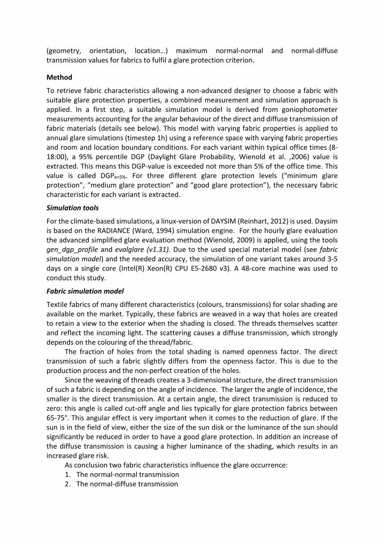
Figure 1: Comparison between simulation model (full lines) and measurements (dashed lines) for the direct-direct transmission (left graph) and for the direct-diffuse transmission (right graph) for the three fabrics.
0
0.01
0.02
0.03
0.04
0.05
0.06
0.07
0.08
0.09
0.1
0 10 20 30 40 50 60 70 80 90
Dir
ect
-Dir
ect
-Tra
nsm
issi
on
[-]
Angle of incidence [°]
Fabric1-measured Fabric1-simulated
Fabric2-measured Fabric2-simulated
Fabric3-measured Fabric3-simulated
0
0.01
0.02
0.03
0.04
0.05
0.06
0.07
0.08
0.09
0.1
0.11
0.12
0.13
0.14
0.15
0 10 20 30 40 50 60 70 80 90
Dir
ect
-Dif
fuse
-Tra
nsm
issi
on
[-]
Angle of incidence [°]
Fabric1-measured Fabric1-simulated
Fabric2-measured Fabric2-simulated
Fabric3-measured Fabric3-simulated
The angular direct-direct and direct-diffuse transmission behaviour of the simulation model for the three fabrics is shown in Figure 1 in comparison to the measurements.
It can be seen that the model reproduces the angular behaviour of the three investigated fabrics. The maximum deviation between measured and simulated transmission values is 0.004 and occurs for the direct-direct transmission of fabric 3. This deviation is acceptable, also considering measurement uncertainties. It can be assumed, that for similar weaved fabrics with other opening factors and/or diffuse transmissions the model can be applied in the same way.
Reference-room geometry and calculation points
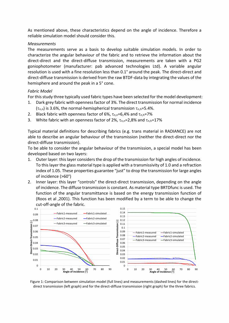
A series of simulations were conducted with a reference office, whose dimensions are expected to create similar “problematic” situations than in an open-plan office. Compared to a smaller office type (i.e. for two or four persons), the duration of the sun in the field of view is much longer and creates potentially more glare situations. The office has a rectangular shape (10 m wide, 5 m deep and 3 m high). Two different façade layouts were used: a façade with 50% glazing fraction (horizontal band) and 70% glazing fraction (glazed from the 1m high sill to the ceiling) – see Figure 2. The reflectance factors (purely diffuse) for the simulations are: 20% for the floor, 60% for the walls and 80% for the ceiling.
Figure 2: Layout of the simulated reference room and calculation points. Left image: Configuration with a 50%
glazing fraction; Middle image: Configuration with a 70% glazing fraction; Right image: Floor plan with calculations points (red dots) and viewing directions (arrows) for the glare calculation.
The glare calculations are conducted on six points and for two viewing directions. The points are located in 1m, 2m and 3m distance to the façade and all of them in 1m distance from the side wall. Viewing direction is either parallel to the façade or facing towards the façade in a 45° angle measured from the parallel axis. Position and direction are illustrated in Figure 2.
Simulation variants and parameters
To receive simple to use data for the choice of a fabric fulfilling a glare criteria, a set of simulations are calculated for different boundary conditions. In the following, these conditions/parameters and their range are listed:
Fabric properties Direct-Direct transmission: 0, 0.01, 0.02, 0.03, 0.05 0.08 Direct-Diffuse transmission: 0, 0.03, 0.06, 0.10, 0.15, 0.20 Cut-off angle 65°, 90°
Window sizes Small window: 50% glazing fraction, Large Window: 70% glazing fraction
10 m
5 m
3 m
10 m
5 m
3 m
Orientations South, Southwest, West, North-West
Locations Rome, Frankfurt, (Stockholm, calculated, but not evaluated in this paper). The EPW-weather files are downloaded from the energyplus web-site (energyplus, 2017).
Visible transmission for the glazing For Frankfurt and Stockholm: 75% as “typical glazing” and 60% as “low transmission glazing”,for Rome: 60% as “typical glazing” and 50% as “low transmission glazing”.
Daysim (Radiance) simulation parameters ab 5, ad 8192, as 4096, ar 256, aa 0.12, lw 0.00002, lr 6, st 0.15, sj 1.0, dp 512. The other parameters are default settings from Daysim.
DGP calculation and thresholds
The glare calculation is based on the Daylight glare probability DGP (Wienold, 2006) and its implementation for climate based simulations (Wienold, 2009). The calculations are conducted at the six calculation points and for the two viewing directions. For each of the points and directions a DGP e<5%-value is extracted. For each combination of distance to façade and viewing direction only the higher value is used. That means only the worst of the two positions (right of left side of the room) is taken; the information about distance and viewing direction is kept. Based on (Wienold, 2009) the different DGP e<5%-threshold values are used to describe the level of glare protection:
1. Good glare protection: DGP e<5% ≤ 0.35 2. Medium glare protection: 0.35 < DGP e<5% ≤ 0.45 3. No glare protection: DGP e<5% > 0.45
Results
The evaluation of the simulation data shows that the strongest influence on the level of glare protection is the direct transmission of the fabric. For that reason, in all upcoming figures the
normal-normal transmission (n,n)of the fabric is used for the x-axis.
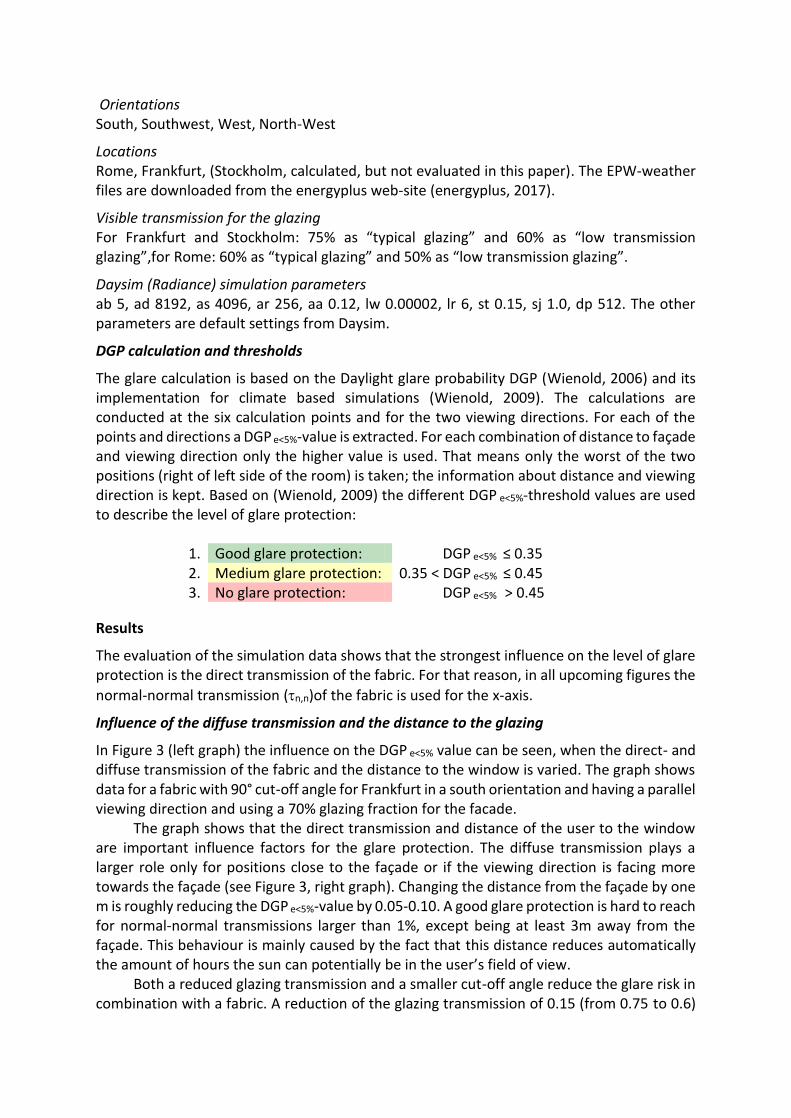
Influence of the diffuse transmission and the distance to the glazing
In Figure 3 (left graph) the influence on the DGP e<5% value can be seen, when the direct- and diffuse transmission of the fabric and the distance to the window is varied. The graph shows data for a fabric with 90° cut-off angle for Frankfurt in a south orientation and having a parallel viewing direction and using a 70% glazing fraction for the facade.
The graph shows that the direct transmission and distance of the user to the window are important influence factors for the glare protection. The diffuse transmission plays a larger role only for positions close to the façade or if the viewing direction is facing more towards the façade (see Figure 3, right graph). Changing the distance from the façade by one m is roughly reducing the DGP e<5%-value by 0.05-0.10. A good glare protection is hard to reach for normal-normal transmissions larger than 1%, except being at least 3m away from the façade. This behaviour is mainly caused by the fact that this distance reduces automatically the amount of hours the sun can potentially be in the user’s field of view.
Both a reduced glazing transmission and a smaller cut-off angle reduce the glare risk in combination with a fabric. A reduction of the glazing transmission of 0.15 (from 0.75 to 0.6)
reduces the DGP e<5% -value between 10-20%. A similar behaviour occurs when using a reduced cut-off angle for the fabric. A change of the cut-off-angle from 90° to 65° results in around 10% reduced DGP e<5% -value (see Figure 3, graph on the right side).
Figure 3: Data for both graphs: Frankfurt, south orientation, parallel viewing direction and 70% glazing
fraction. Left image: Influence of the direct and diffuse transmission and the distance to the window on the level of glare protection (DGP e<5%). Cut-off-angle of the fabric is 90° and glazing transmission 75%.
Right image: Influence of the glazing transmission and the cut-off-angle of the fabric on the DGP e<5%. Distance to the façade is 2m and the normal-diffuse transmission of the fabric is 0.10.
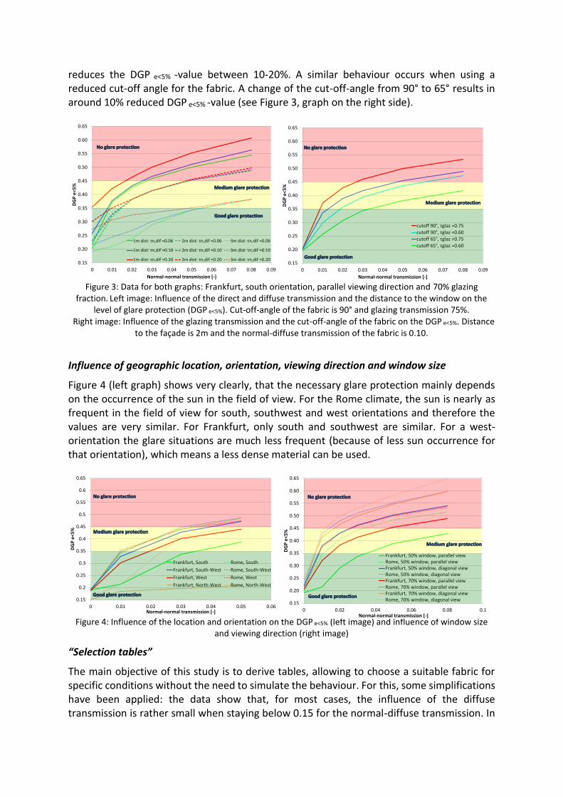
Influence of geographic location, orientation, viewing direction and window size
Figure 4 (left graph) shows very clearly, that the necessary glare protection mainly depends on the occurrence of the sun in the field of view. For the Rome climate, the sun is nearly as frequent in the field of view for south, southwest and west orientations and therefore the values are very similar. For Frankfurt, only south and southwest are similar. For a west-orientation the glare situations are much less frequent (because of less sun occurrence for that orientation), which means a less dense material can be used.
Figure 4: Influence of the location and orientation on the DGP e<5% (left image) and influence of window size
and viewing direction (right image)
“Selection tables”
The main objective of this study is to derive tables, allowing to choose a suitable fabric for specific conditions without the need to simulate the behaviour. For this, some simplifications have been applied: the data show that, for most cases, the influence of the diffuse transmission is rather small when staying below 0.15 for the normal-diffuse transmission. In
0.15
0.20
0.25
0.30
0.35
0.40
0.45
0.50
0.55
0.60
0.65
0 0.01 0.02 0.03 0.04 0.05 0.06 0.07 0.08 0.09
DG
P e
<5
%
Normal-normal transmission [-]
1m dist: τn,dif =0.06 2m dist: τn,dif =0.06 3m dist: τn,dif =0.06
1m dist: τn,dif =0.10 2m dist: τn,dif =0.10 3m dist: τn,dif =0.10
1m dist: τn,dif =0.20 2m dist: τn,dif =0.20 3m dist: τn,dif =0.200.15
0.20
0.25
0.30
0.35
0.40
0.45
0.50
0.55
0.60
0.65
0 0.01 0.02 0.03 0.04 0.05 0.06 0.07 0.08 0.09
DG
P e
<5
%
Normal-normal transmission [-]
cutoff 90°, τglaz =0.75
cutoff 90°, τglaz =0.60
cutoff 65°, τglaz =0.75
cutoff 65°, τglaz =0.60
0.15
0.2
0.25
0.3
0.35
0.4
0.45
0.5
0.55
0.6
0.65
0 0.01 0.02 0.03 0.04 0.05 0.06
DG
P e
<5
%
Normal-normal transmission [-]
Frankfurt, South Rome, South
Frankfurt, South-West Rome, South-West
Frankfurt, West Rome, West
Frankfurt, North-West Rome, North-West
0.15
0.20
0.25
0.30
0.35
0.40
0.45
0.50
0.55
0.60
0.65
0 0.02 0.04 0.06 0.08 0.1
DG
P e
<5
%
Normal-normal transmission [-]
Frankfurt, 50% window, parallel viewRome, 50% window, parallel viewFrankfurt, 50% window, diagonal viewRome, 50% window, diagonal viewFrankfurt, 70% window, parallel viewRome, 70% window, parallel viewFrankfurt, 70% window, diagonal viewRome, 70% window, diagonal view
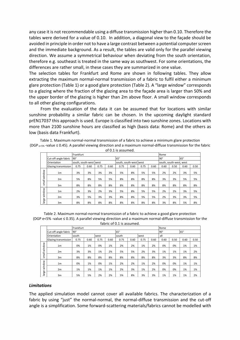
any case it is not recommendable using a diffuse transmission higher than 0.10. Therefore the tables were derived for a value of 0.10. In addition, a diagonal view to the façade should be avoided in principle in order not to have a large contrast between a potential computer screen and the immediate background. As a result, the tables are valid only for the parallel viewing direction. We assume a symmetrical behaviour when deviating from the south orientation, therefore e.g. southeast is treated in the same way as southwest. For some orientations, the differences are rather small, in these cases they are summarized in one value. The selection tables for Frankfurt and Rome are shown in following tables. They allow extracting the maximum normal-normal transmission of a fabric to fulfil either a minimum glare protection (Table 1) or a good glare protection (Table 2). A “large window” corresponds to a glazing where the fraction of the glazing area to the façade area is larger than 50% and the upper border of the glazing is higher than 2m above floor. A small window corresponds to all other glazing configurations.
From the evaluation of the data it can be assumed that for locations with similar sunshine probability a similar fabric can be chosen. In the upcoming daylight standard prEN17037 this approach is used. Europe is classified into two sunshine zones. Locations with more than 2100 sunshine hours are classified as high (basis data: Rome) and the others as low (basis data Frankfurt).
Table 1. Maximum normal-normal transmission of a fabric to achieve a minimum glare protection (DGP e<5% -value ≤ 0.45). A parallel viewing direction and a maximum normal-diffuse transmission for the fabric
of 0.1 is assumed.
Table 2. Maximum normal-normal transmission of a fabric to achieve a good glare protection (DGP e<5% -value ≤ 0.35). A parallel viewing direction and a maximum normal-diffuse transmission for the
fabric of 0.1 is assumed.
Limitations
The applied simulation model cannot cover all available fabrics. The characterization of a fabric by using “just” the normal-normal, the normal-diffuse transmission and the cut-off angle is a simplification. Some forward-scattering materials/fabrics cannot be modelled with
Cut-off-angle fabric
Orientation
Glazing transmission 0.75 0.60 0.75 0.60 0.75 0.60 0.75 0.60 0.60 0.50 0.60 0.50
1m 3% 3% 3% 3% 5% 8% 5% 5% 2% 2% 3% 5%
2m 5% 8% 5% 5% 8% 8% 8% 8% 3% 3% 5% 5%
3m 8% 8% 8% 8% 8% 8% 8% 8% 8% 8% 8% 8%
1m 2% 3% 2% 3% 5% 8% 5% 5% 2% 2% 3% 5%
2m 3% 5% 3% 3% 8% 8% 5% 5% 2% 3% 3% 5%
3m 8% 8% 8% 8% 8% 8% 8% 8% 3% 8% 5% 8%
south, south-west, west
Frankfurt Rome
90° 65° 90° 65°
smal
l win
do
wla
rge
win
do
w
south, south-west west south, south-west west
Cut-off-angle fabric
Orientation
Glazing transmission 0.75 0.60 0.75 0.60 0.75 0.60 0.75 0.60 0.60 0.50 0.60 0.50
1m 0% 1% 0% 1% 2% 2% 1% 2% 0% 0% 1% 1%
2m 3% 3% 1% 2% 5% 5% 2% 3% 1% 1% 1% 2%
3m 8% 8% 8% 8% 8% 8% 8% 8% 3% 3% 8% 8%
1m 0% 1% 0% 1% 2% 2% 1% 2% 0% 0% 1% 1%
2m 1% 1% 1% 1% 2% 3% 1% 2% 0% 0% 1% 1%
3m 5% 5% 2% 2% 5% 8% 3% 3% 1% 1% 1% 2%
south west south west all
90° 65° 90° 65°
larg
e w
ind
ow
Frankfurt Rome
smal
l win
do
w
this simplification; in that case a detailed BTDF is necessary. In addition the DGP in its current form underestimates contrasted glare in darker situations. Also, the study also does not consider reflections on a computer screen. The applied method is limited to spaces, where the usage is similar to office type tasks (reading/writing on computer screen and/or paper).
Conclusions
Intensive simulations of different fabric types under different conditions have been conducted to derive simplified tables, which enables a designer to choose a suitable fabric. Fabrics with a smaller cut-off-angle should be preferred in general– they allow higher normal-normal transmission and a better view to the exterior. Currently the cut-off angle is not provided by the manufacturers, but with the revision of the EN14501 they will be encouraged to produce fabrics with smaller cut-off angles and to provide this data. The results of these calculations are also the basis of the revision of the standard EN14501 (“Performance characteristics and classification of a solar protection device or roller shutter with regard to visual and thermal comfort”). In that standard, a classification for fabrics based on DGPe<5% and reflections on a computer screen is used. Also the glare evaluation in the new European Daylight Standard EN17037 (“Daylight of buildings”) is based on the presented methodology.
Acknowledgements
This study was supported by the École Polytechnique Fédérale de Lausanne (EPFL) and was co-funded by the Velux Group, Mermet S.A.S. and SNFPSA.
References
C. F. Reinhart (2012), Daysim version 3.0. <http://daysim.com>. A. Roos, P. Polato, P.A. van Nijnatten, M.G. Hutchins, F. Olive, C. Anderson (2001). Angular-dependent
optical properties of low-e and solar control windows - simulations versus measurements, Solar Energy 69 (suppl.\ 6) (2001) 15-26.
J. Wienold (2009), Dynamic Daylight Glare evaluation, Building Simulation, Glasgow, 2009, pp. 944-951. J. Wienold, J. Christoffersen (2006), Evaluation methods and development of a new glare prediction
model for daylight environments with the use of CCD cameras, Energy and Buildings, 38(7):743-757. A. Tzempelikos, Y. Chan (2016), Estimating detailed optical properties of window shades from basic
available data and modeling implications on daylighting and visual comfort, Energy and Buildings, Volume 126, 15 August 2016, Pages 396-407.
G. J. Ward (1994), The RADIANCE Lighting Simulation and Rendering System, Computer Graphics (Proceedings of '94 SIGGRAPH conference), pp. 459-72, July 1994.
European Committee for Standardization CEN (2017), Revision of draft Standard prEN17037:2016, Daylight of buildings.
European Committee for Standardization CEN (2017), Revision of Standard EN14501:2005, Performance characteristics and classification of a solar protection device or roller shutter with regard to visual and thermal comfort.
J. C. Jonsson ; E. S. Lee and M. Rubin (2008), Light-scattering properties of a woven shade-screen material used for daylighting and solar heat-gain control, Proc. SPIE 7065, Reflection, Scattering, and Diffraction from Surfaces, 70650R
Deneyer, A., Deroisy, B., et al. (2014). "Bi-Directional Scattering Distribution Data of Solar Shading: Characterization and Performances." Retrieved 04/09, 2017, from http://www.cstc.be/homepage/download.cfm?dtype=research&doc=CIE_2013_Bi_Directional_Scattering_Distribution_of_solar_shading.pdf&lang=en
Energy Plus (2017). Weather files available at https://energyplus.net/weather/sources.


![pascal.frossard@epfl.ch arXiv:1610.08401v1 [cs.CV] 26 … · Universal adversarial perturbations Seyed-Mohsen Moosavi-Dezfooli y seyed.moosavi@epfl.ch Alhussein Fawzi alhussein.fawzi@epfl.ch](https://img.pdfslide.us/doc/110x75/5aeb0a947f8b9a36698dd145/epflch-arxiv161008401v1-cscv-26-adversarial-perturbations-seyed-mohsen.jpg)