Embed Size (px)
Citation preview
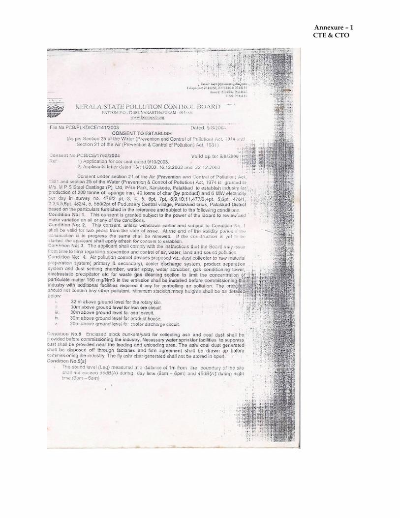
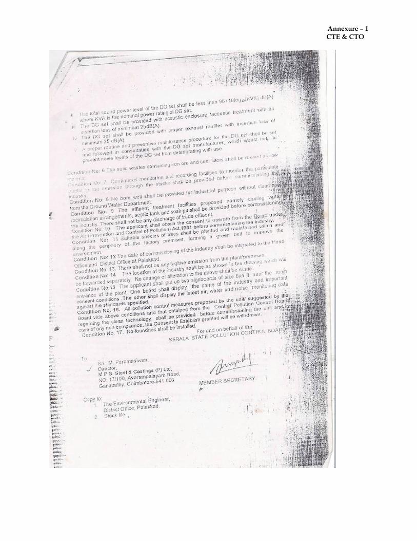
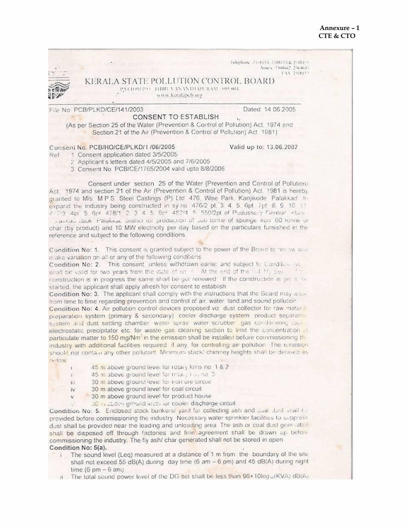
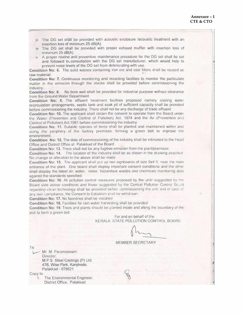
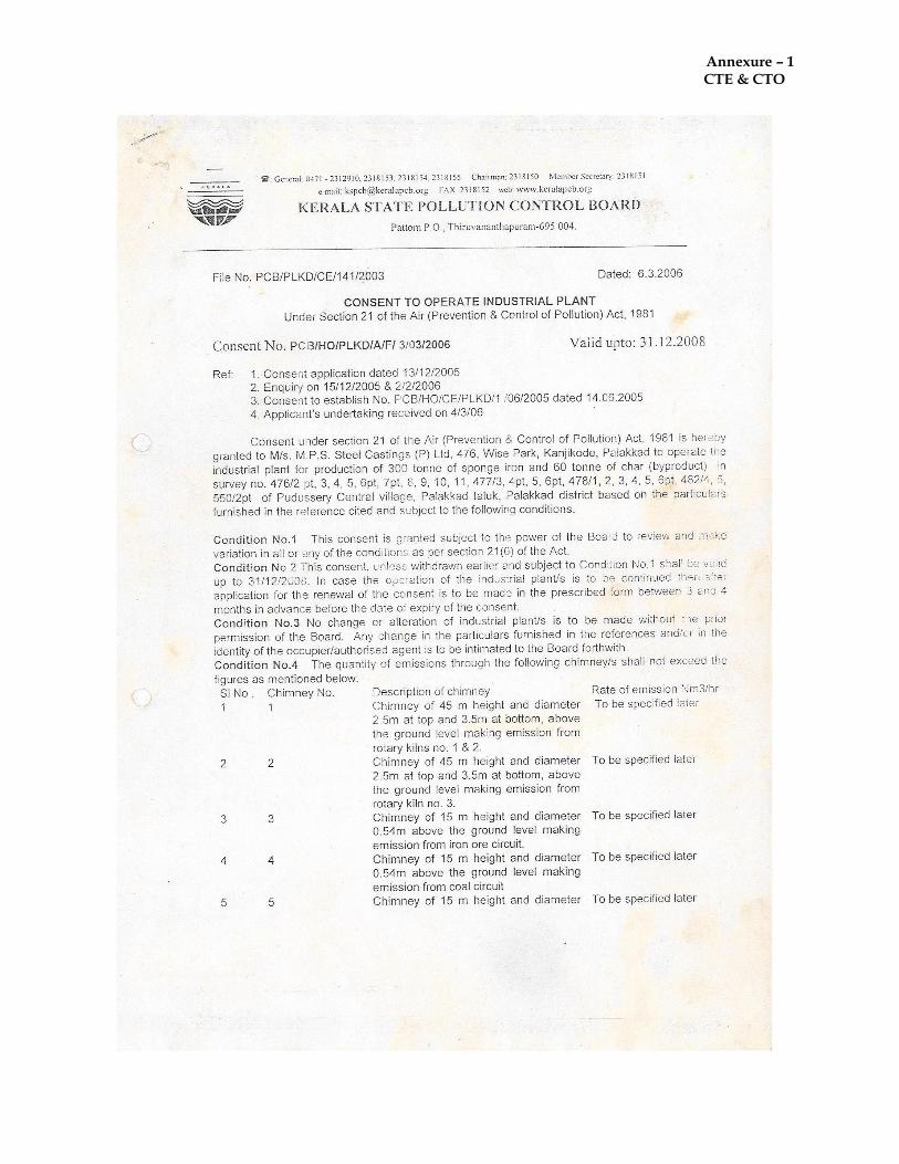
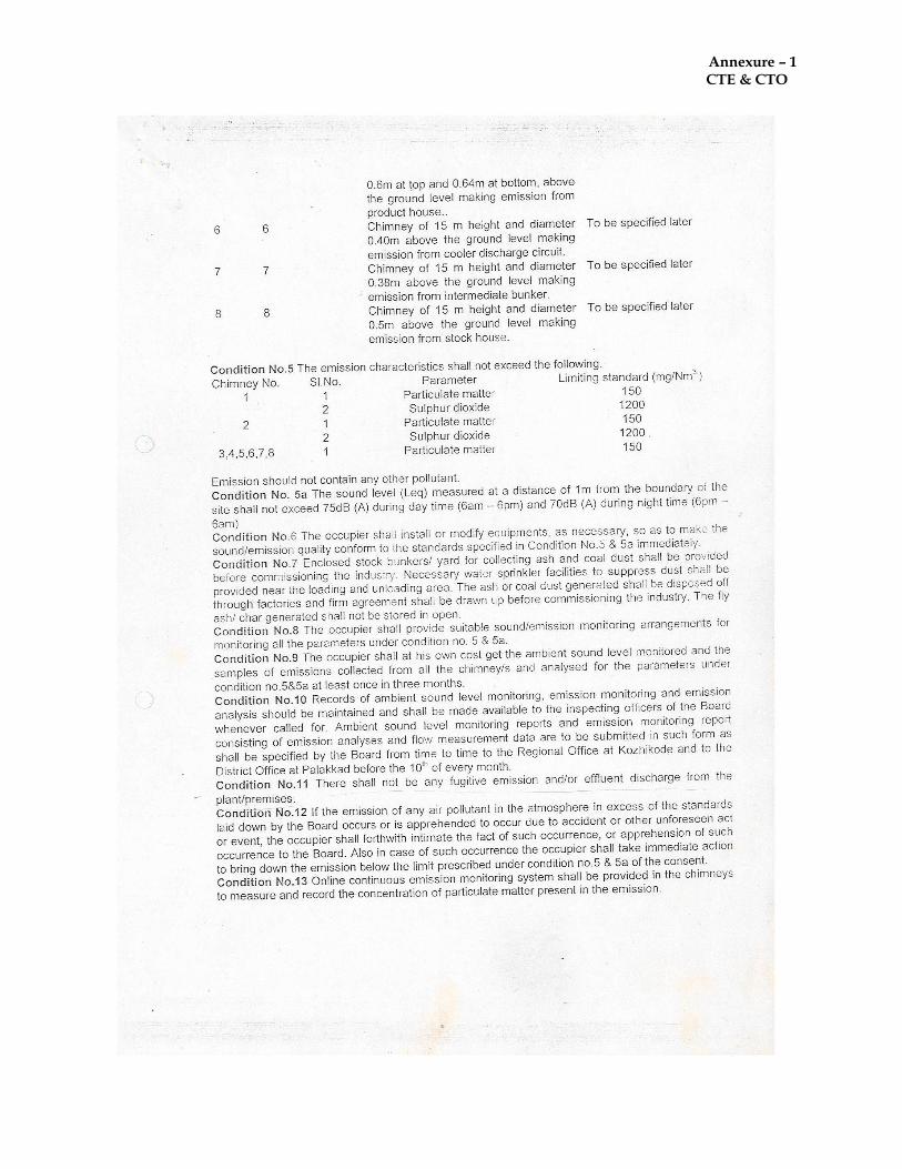
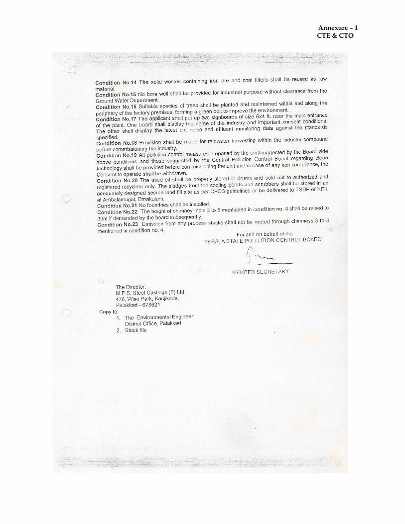
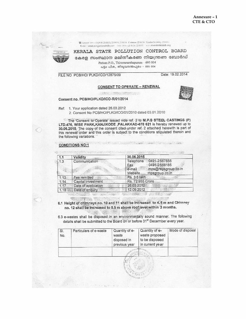
Annexure – 1 CTE & CTO
Annexure – 1 CTE & CTO
Annexure – 1 CTE & CTO
Annexure – 1 CTE & CTO
Annexure – 1 CTE & CTO
Annexure – 1 CTE & CTO
Annexure – 1 CTE & CTO
Annexure – 1 CTE & CTO
Annexure – 1 CTE & CTO
Annexure - 2 Process Description
PROJECT DESCRIPTION
The Proposed activity is an Integrated Steel Plant along with Melting Unit, Re-rolling Mill, Sponge Iron Plant, Power Generation and Ferro Alloys. MANUFACTURING PROCESS / PROCESS DESCRIPTION
MS BILLETS The greatest advantage of the Induction Furnace is its low capital cost compared with other types of Melting Units. Its installation is relatively easier and its operation simpler. Among other advantages, there is very little heat loss from the furnace as the bath is constantly covered and there is practically no noise during its operation. The molten metal in an Induction Furnace is circulated automatically by electromagnetic action so that when alloy additions are made, a homogeneous product is ensured in minimum time. The time between tap and charge, the charging time, power delays etc, are items of utmost importance are meeting the objective of maximum output in tones/hour at a low operational coast. The process for manufacturing steel may be broadly divided into the following stages:
Melting the charge mixed of steel & iron scrap.
Ladle teeming practice for casting.
Continuous casting machine. MELTING THE CHARGE The furnace is switched on, current starts flowing at a high rate and a comparatively low voltage through the induction coils of the furnace, producing an induced magnetic field inside the central space of the coils where the crucible is located. The induced magnetic fluxes thus generated out through the packed charge in the crucible, which is placed centrally inside the induction coil. As the magnetic fluxes generated out through the scraps and complete the circuit, they generate and induce eddy current in the scrap. This induced eddy current, as it flows through the highly melting rate depends primarily on two things,
1. The density of magnetic fluxes and 2. Compactness of the charge.
The charge mixed arrangement has already been described. The magnetic fluxes can be controlled by varying input of power to the furnace, especially the current and frequency.
Annexure - 2 Process Description
In a medium frequency furnace, the frequency range normally varies between 150-10000 cycles/second. This heat is developed mainly in the outer rim of the metal in the charge but is carried quickly to the center by conduction. Soon a pool of molten metal forms in the bottom causing the charge to sink. At this point any remaining charge mixed is added gradually. The eddy current, which is generated in the charge, has other uses. It imparts a molten effect on the liquid steel, which is thereby stirred and mixed and heated more homogeneously. This stirring effect is inversely proportional to the frequency of the furnace and so that furnace frequency is selected in accordance with the purpose for which the furnace will be utilized. The melting continues till all the charge is melted and the bath develops a convex surface. However as the convex surface is not favorable to slag treatment, the power input is then naturally decreased to flatten the convexity and to reduce the circulation rate when refining under constantly bringing new metal into close contact with the slag. Before the actual reduction of steel id done, the liquid steel which might contain some trapped oxygen is first treated with some suitable deoxidizer. When no purification is attempted, the chief metallurgical advantages of the process attributable to the stirring action are uniformity of the product, control over the super heat temperature and the opportunity afforded by the conditions of the melt to control de-oxidation through proper addition. As soon as the charge has melted and de-oxidising ions have ceased. Any objectionable slag is skimmed off, and the necessary alloying elements are added. When these additives have melted and diffused through the bath of the power input may be increased to bring the temperature of metal up to the point most desirable for pouring. The current is then turned off and the furnace is tilted for pouring into a ladle. As soon as pouring has ceased, any slag adhering to the wall of the crucible is crapped out and the furnace is readied for charging again. As the furnace is equipped with a higher cover over the crucible very little oxidation occurs during melting. Such a cover also serves to prevent cooling by radiation from the surface heat loss and protecting the metal is unnecessary, though slags are used in special cases. Another advantage of the induction furnace is that there is hardly any melting loss compared with the arc furnace. LADDLE TEEMING PRACTISE The temperature of liquid metal is allowed to rise in the furnace till the correct pouring temperature is achieved which is checked with the help of Immersion Pyrometer. The hot metal is poured with the hydraulic system in the preheated ladle after adding certain fluxes so that the temperature is maintained at about 1600 degree centigrade. Ladle is then carried by EOT charge to the concast machine and (crucible is made free
Annexure - 2 Process Description
for further charge of next batch) kept above the tundish of the concast machine. The bottom of the ladle is opened by hydraulic system and hot metal starts pouring out into the concast machine. CONTINUOUS CASTING MACHINE The molten steel from the IF or the ladle metallurgical facility is cast in a continuous casting machine (6/11 2 stand Billet Caster) to produce cast shapes including billets. In some processes, the cast shape is torch cut to length and transported hot to the hot rolling mill for further processing. Other steel mills have reheat furnaces. Steel billets are allowed to cool, and then be reheated in a furnace prior to rolling the billets into bars or other shapes. Castings operations consist of following:-
Preparation
Match Plates (Patterns)
Preparation of Moulds
Pouring of molten steel into prepared moulds
Knocking of moulds
Finishing of casting billets
1. The process is continuous because liquid steel is continuously poured into a ‘bottomless’ mould at the same rate as a continuous steel casting is extracted.
2. Before casting beings a dummy bar is used to close the bottom of the mould.
3. A ladle of molten steel is lifted above the casting machine and a hole in t he bottom of the ladle is opened, allowing the liquid steel to pour into the mould to form the required shape.
4. As the steel’s outer surface solidifies in the mould, the dummy bar is slowly withdrawn through the machine, pulling the steel with it.
5. Water sprays along the machine to cool / solidify the steel.
6. At the end of the machine, the billets are cut to the required length of 6 mtrs or 12 mtrs by gas torches.
7. Sized billets are lifted by crane to finishing yard for inspection and storage / dispatch.
Annexure - 2 Process Description
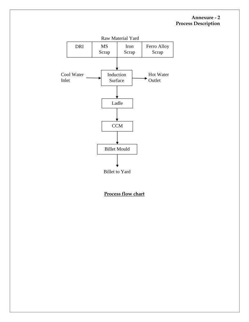
Process flow chart
Raw Material Yard
DRI MS
Scrap
Iron
Scrap
Ferro Alloy
Scrap
Induction
Surface
Cool Water
Inlet
Hot Water
Outlet
Ladle
CCM
Billet Mould
Billet to Yard
Annexure - 2 Process Description
THERMOMECHANICAL PROCESSING (TMT) Thermomechanical Processing, also known as thermo-mechanical treatment (TMT), is a metallurgical process that integrates work hardening and heat-treatment into a single process. A description of its application in rebar steel follows. Mild steel billets of sizes 100/110/125 mm² having the appropriate chemical constituent i.e. Carbon, Manganese, Sulphur and Phosphorus are hated to the temperature of appx. 1150°C – 12200°C in the reheating furnace. The heated raw material is passed through a series of electronically controlled Rolling Mills stands to produce the finished steel at a temperature of around 950°C – 1000°C. TMT bars are produced using the latest quenching process in automatic rolling mill where TMT bars are hot rolled from tested raw material of required chemical specification in a series of electronically controlled finishing stands and online PLC controlled thermo mechanical treatment they are progressively rolled to reduce the billets to the final size and shape of reinforcing bar. After the last rolling stand, the billet moves through a quench box. The quenching converts the billet’s surface layer to martensite, and causes it to shrink. The shrinkage pressurizes the core, helping to form the correct crystal structures. The core remains hot, and austenitic. A microprocessor controls the water flow to the quench box, to manage the temperature difference through the cross-section of the bars. The correct temperature difference assures that all processes occur, and bars have the necessary mechanical properties. The bar leaves the quench box with a temperature gradient through its cross section. As the bar cools, heat flows from the bar’s centre to its surface so that the bar’s heat and pressure correctly tempers and intermediate ring of martensite and bainite. Finally, the slow cooling after quenching automatically tempers the austenitic core to ferrite and pearlite on the cooling bed. These bars therefore exhibit a variation in microstructure in their cross section, having strong, tough, tempered martensite in the surface layer of the bar, an intermediate layer of martensite and bainite, and a refined, tough and ductile ferrite and pearlite core. When the cut ends of TMT bars are etched in Nital (a mixture of nitric acid and methanol), three distinct rings appear;
1. A tempered outer ring of martensite, 2. A semi-tempered middle ring of martensite and bainite, and 3. A mild circular core of bainite, ferrite and pearlite.
This is the desired micro structure for quality construction rebar.

Annexure - 2 Process Description
In contrast, lower grades of rebar are twisted when cold, work hardening them to increase their strength. However, after thermo mechanical treatment (TMT), bars do not need more work hardening. As there is no twisting during TMT, no torsional stress occurs, and so torsional stress cannot form surface defects in TMT Bars. Therefore TMT bars resist corrosion better than cold, twisted and deformed (CTD).
Annexure - 2 Process Description
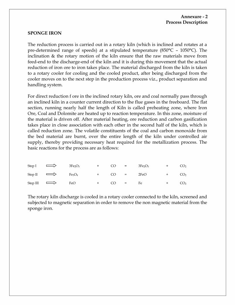
SPONGE IRON The reduction process is carried out in a rotary kiln (which is inclined and rotates at a pre-determined range of speeds) at a stipulated temperature (850°C – 1050°C). The inclination & the rotary motion of the kiln ensure that the raw materials move from feed-end to the discharge-end of the kiln and it is during this movement that the actual reduction of iron ore to iron takes place. The material discharged from the kiln is taken to a rotary cooler for cooling and the cooled product, after being discharged from the cooler moves on to the next step in the production process viz., product separation and handling system. For direct reduction f ore in the inclined rotary kiln, ore and coal normally pass through an inclined kiln in a counter current direction to the flue gases in the freeboard. The flat section, running nearly half the length of Kiln is called preheating zone, where Iron Ore, Coal and Dolomite are heated up to reaction temperature. In this zone, moisture of the material is driven off. After material heating, ore reduction and carbon gasification takes place in close association with each other in the second half of the kiln, which is called reduction zone. The volatile constituents of the coal and carbon monoxide from the bed material are burnt, over the entire length of the kiln under controlled air supply, thereby providing necessary heat required for the metallization process. The basic reactions for the process are as follows: Step I 3Fe2O3 + CO = 3Fe2O3 + CO2 Step II Fe3O4 + CO = 2FeO + CO2 Step III FeO + CO = Fe + CO2
The rotary kiln discharge is cooled in a rotary cooler connected to the kiln, screened and subjected to magnetic separation in order to remove the non magnetic material from the sponge iron.
Annexure - 2 Process Description
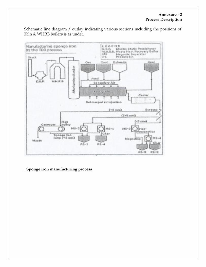
Schematic line diagram / outlay indicating various sections including the positions of Kiln & WHRB boilers is as under.
Sponge iron manufacturing process
Annexure - 2 Process Description
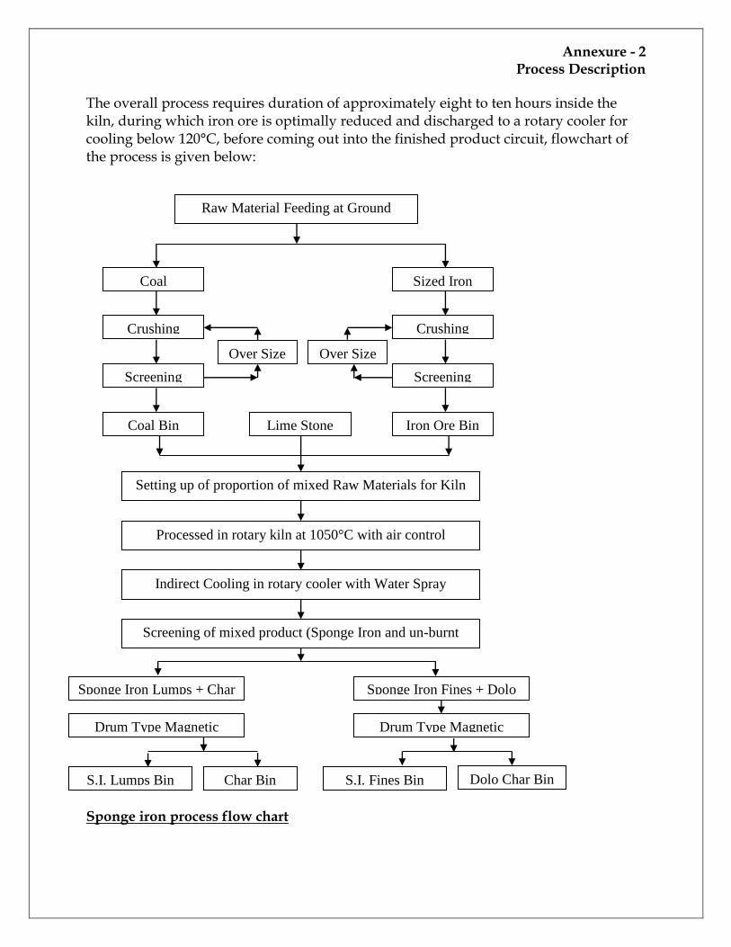
The overall process requires duration of approximately eight to ten hours inside the kiln, during which iron ore is optimally reduced and discharged to a rotary cooler for cooling below 120°C, before coming out into the finished product circuit, flowchart of the process is given below: Sponge iron process flow chart
Raw Material Feeding at Ground
Hopper
Coal
Crushing
Screening
Coal Bin
Sized Iron
Ore
Crushing
Screening
Iron Ore Bin
Over Size Over Size
Lime Stone
Bin
Setting up of proportion of mixed Raw Materials for Kiln
Feed
Processed in rotary kiln at 1050°C with air control
Indirect Cooling in rotary cooler with Water Spray
Screening of mixed product (Sponge Iron and un-burnt
Coal)
Sponge Iron Lumps + Char Sponge Iron Fines + Dolo
Drum Type Magnetic Drum Type Magnetic
S.I. Lumps Bin Char Bin S.I. Fines Bin Dolo Char Bin
Annexure - 2 Process Description
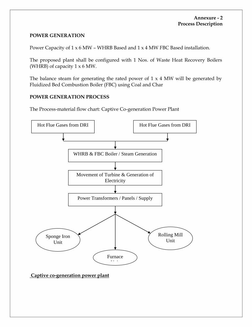
POWER GENERATION Power Capacity of 1 x 6 MW – WHRB Based and 1 x 4 MW FBC Based installation. The proposed plant shall be configured with 1 Nos. of Waste Heat Recovery Boilers (WHRB) of capacity 1 x 6 MW. The balance steam for generating the rated power of 1 x 4 MW will be generated by Fluidized Bed Combustion Boiler (FBC) using Coal and Char POWER GENERATION PROCESS The Process-material flow chart: Captive Co-generation Power Plant Captive co-generation power plant
Hot Flue Gases from DRI Hot Flue Gases from DRI
WHRB & FBC Boiler / Steam Generation
Movement of Turbine & Generation of
Electricity
Power Transformers / Panels / Supply
Sponge Iron
Unit
Rolling Mill
Unit
Furnace
Unit
Annexure -3 Waste generation & management
WASTE & WASTE MANAGEMENT
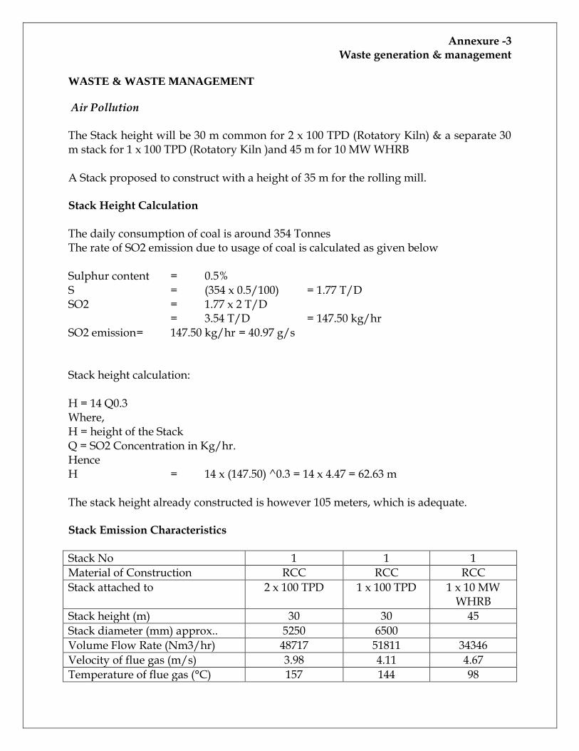
Air Pollution The Stack height will be 30 m common for 2 x 100 TPD (Rotatory Kiln) & a separate 30 m stack for 1 x 100 TPD (Rotatory Kiln )and 45 m for 10 MW WHRB A Stack proposed to construct with a height of 35 m for the rolling mill. Stack Height Calculation The daily consumption of coal is around 354 Tonnes The rate of SO2 emission due to usage of coal is calculated as given below Sulphur content = 0.5% S = (354 x 0.5/100) = 1.77 T/D SO2 = 1.77 x 2 T/D = 3.54 T/D = 147.50 kg/hr SO2 emission = 147.50 kg/hr = 40.97 g/s Stack height calculation: H = 14 Q0.3 Where, H = height of the Stack Q = SO2 Concentration in Kg/hr. Hence H = 14 x (147.50) ^0.3 = 14 x 4.47 = 62.63 m The stack height already constructed is however 105 meters, which is adequate. Stack Emission Characteristics
Stack No 1 1 1
Material of Construction RCC RCC RCC
Stack attached to 2 x 100 TPD 1 x 100 TPD 1 x 10 MW WHRB
Stack height (m) 30 30 45
Stack diameter (mm) approx.. 5250 6500
Volume Flow Rate (Nm3/hr) 48717 51811 34346
Velocity of flue gas (m/s) 3.98 4.11 4.67
Temperature of flue gas (°C) 157 144 98
Annexure -3 Waste generation & management
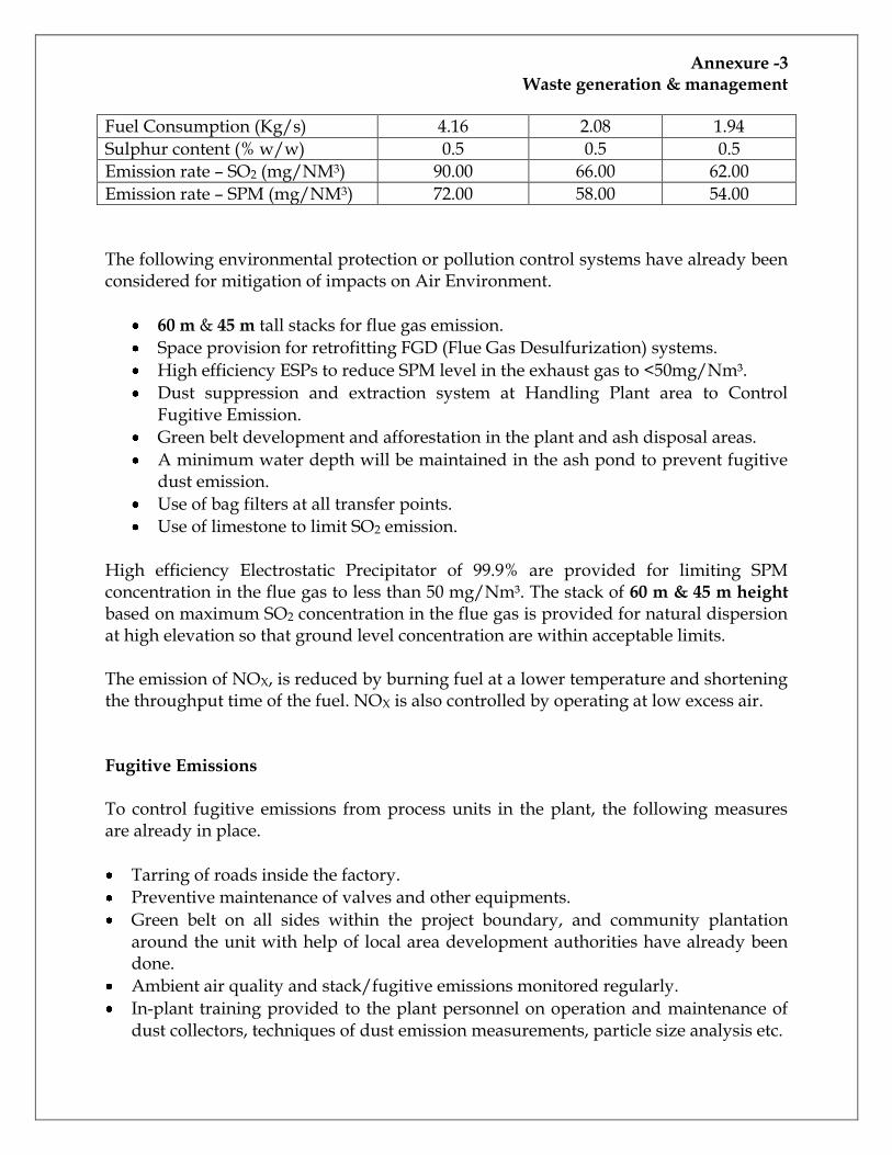
Fuel Consumption (Kg/s) 4.16 2.08 1.94
Sulphur content (% w/w) 0.5 0.5 0.5
Emission rate – SO2 (mg/NM3) 90.00 66.00 62.00
Emission rate – SPM (mg/NM3) 72.00 58.00 54.00 The following environmental protection or pollution control systems have already been considered for mitigation of impacts on Air Environment.
60 m & 45 m tall stacks for flue gas emission.
Space provision for retrofitting FGD (Flue Gas Desulfurization) systems.
High efficiency ESPs to reduce SPM level in the exhaust gas to <50mg/Nm³.
Dust suppression and extraction system at Handling Plant area to Control Fugitive Emission.
Green belt development and afforestation in the plant and ash disposal areas.
A minimum water depth will be maintained in the ash pond to prevent fugitive dust emission.
Use of bag filters at all transfer points.
Use of limestone to limit SO2 emission. High efficiency Electrostatic Precipitator of 99.9% are provided for limiting SPM concentration in the flue gas to less than 50 mg/Nm³. The stack of 60 m & 45 m height based on maximum SO2 concentration in the flue gas is provided for natural dispersion at high elevation so that ground level concentration are within acceptable limits. The emission of NOX, is reduced by burning fuel at a lower temperature and shortening the throughput time of the fuel. NOX is also controlled by operating at low excess air. Fugitive Emissions To control fugitive emissions from process units in the plant, the following measures are already in place.
Tarring of roads inside the factory.
Preventive maintenance of valves and other equipments.
Green belt on all sides within the project boundary, and community plantation around the unit with help of local area development authorities have already been done.
Ambient air quality and stack/fugitive emissions monitored regularly.
In-plant training provided to the plant personnel on operation and maintenance of dust collectors, techniques of dust emission measurements, particle size analysis etc.
Annexure -3 Waste generation & management
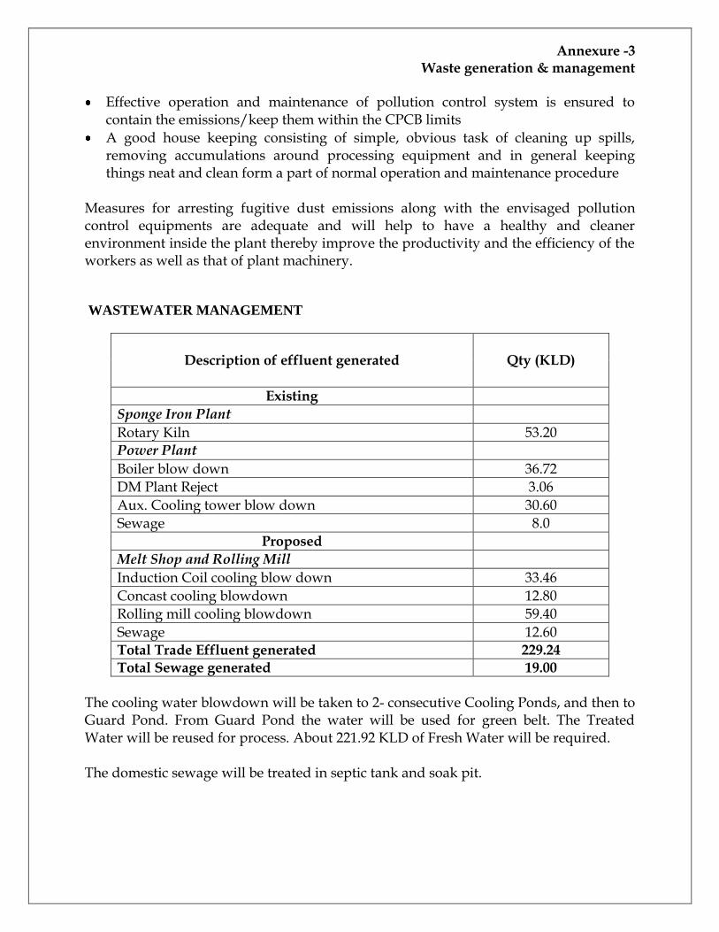
Effective operation and maintenance of pollution control system is ensured to contain the emissions/keep them within the CPCB limits
A good house keeping consisting of simple, obvious task of cleaning up spills, removing accumulations around processing equipment and in general keeping things neat and clean form a part of normal operation and maintenance procedure
Measures for arresting fugitive dust emissions along with the envisaged pollution control equipments are adequate and will help to have a healthy and cleaner environment inside the plant thereby improve the productivity and the efficiency of the workers as well as that of plant machinery.
WASTEWATER MANAGEMENT
Description of effluent generated Qty (KLD)
Existing Sponge Iron Plant
Rotary Kiln 53.20 Power Plant
Boiler blow down 36.72
DM Plant Reject 3.06
Aux. Cooling tower blow down 30.60
Sewage 8.0
Proposed Melt Shop and Rolling Mill
Induction Coil cooling blow down 33.46
Concast cooling blowdown 12.80
Rolling mill cooling blowdown 59.40
Sewage 12.60 Total Trade Effluent generated 229.24
Total Sewage generated 19.00
The cooling water blowdown will be taken to 2- consecutive Cooling Ponds, and then to Guard Pond. From Guard Pond the water will be used for green belt. The Treated Water will be reused for process. About 221.92 KLD of Fresh Water will be required. The domestic sewage will be treated in septic tank and soak pit.
Annexure -3 Waste generation & management
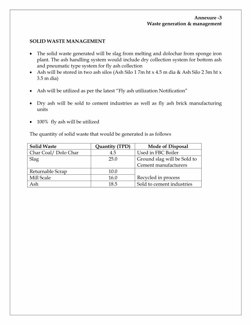
SOLID WASTE MANAGEMENT
The solid waste generated will be slag from melting and dolochar from sponge iron plant. The ash handling system would include dry collection system for bottom ash and pneumatic type system for fly ash collection
Ash will be stored in two ash silos (Ash Silo 1 7m ht x 4.5 m dia & Ash Silo 2 3m ht x 3.5 m dia)
Ash will be utilized as per the latest “Fly ash utilization Notification”
Dry ash will be sold to cement industries as well as fly ash brick manufacturing units
100% fly ash will be utilized The quantity of solid waste that would be generated is as follows Solid Waste Quantity (TPD) Mode of Disposal
Char Coal/ Dolo Char 4.5 Used in FBC Boiler
Slag 25.0 Ground slag will be Sold to Cement manufacturers
Returnable Scrap 10.0 Recycled in process Mill Scale 16.0
Ash 18.5 Sold to cement industries
Annexure- -4 Emission details & APC measures
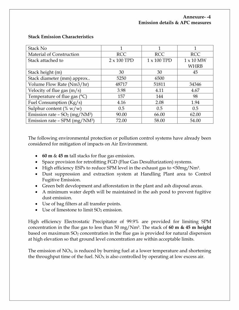
Stack Emission Characteristics
Stack No 1 1 1
Material of Construction RCC RCC RCC
Stack attached to 2 x 100 TPD 1 x 100 TPD 1 x 10 MW WHRB
Stack height (m) 30 30 45
Stack diameter (mm) approx.. 5250 6500
Volume Flow Rate (Nm3/hr) 48717 51811 34346
Velocity of flue gas (m/s) 3.98 4.11 4.67
Temperature of flue gas (°C) 157 144 98
Fuel Consumption (Kg/s) 4.16 2.08 1.94
Sulphur content (% w/w) 0.5 0.5 0.5
Emission rate – SO2 (mg/NM3) 90.00 66.00 62.00
Emission rate – SPM (mg/NM3) 72.00 58.00 54.00 The following environmental protection or pollution control systems have already been considered for mitigation of impacts on Air Environment.
60 m & 45 m tall stacks for flue gas emission.
Space provision for retrofitting FGD (Flue Gas Desulfurization) systems.
High efficiency ESPs to reduce SPM level in the exhaust gas to <50mg/Nm³.
Dust suppression and extraction system at Handling Plant area to Control Fugitive Emission.
Green belt development and afforestation in the plant and ash disposal areas.
A minimum water depth will be maintained in the ash pond to prevent fugitive dust emission.
Use of bag filters at all transfer points.
Use of limestone to limit SO2 emission. High efficiency Electrostatic Precipitator of 99.9% are provided for limiting SPM concentration in the flue gas to less than 50 mg/Nm³. The stack of 60 m & 45 m height based on maximum SO2 concentration in the flue gas is provided for natural dispersion at high elevation so that ground level concentration are within acceptable limits. The emission of NOX, is reduced by burning fuel at a lower temperature and shortening the throughput time of the fuel. NOX is also controlled by operating at low excess air.
Annexure- -4 Emission details & APC measures
Fugitive Emissions To control fugitive emissions from process units in the plant, the following measures are already in place.
Tarring of roads inside the factory.
Preventive maintenance of valves and other equipments.
Green belt on all sides within the project boundary, and community plantation around the unit with help of local area development authorities have already been done.
Ambient air quality and stack/fugitive emissions monitored regularly.
In-plant training provided to the plant personnel on operation and maintenance of dust collectors, techniques of dust emission measurements, particle size analysis etc.
Effective operation and maintenance of pollution control system is ensured to contain the emissions/keep them within the CPCB limits
A good house keeping consisting of simple, obvious task of cleaning up spills, removing accumulations around processing equipment and in general keeping things neat and clean form a part of normal operation and maintenance procedure
Measures for arresting fugitive dust emissions along with the envisaged pollution control equipments are adequate and will help to have a healthy and cleaner environment inside the plant thereby improve the productivity and the efficiency of the workers as well as that of plant machinery.