Embed Size (px)
Citation preview

Annexure 01
Existing Base System

Page 2
Contents Abbreviations ............................................................................................................................................ 5
1. Overview of Current Solution ......................................................................................................6
A. Existing Base System ......................................................................................................................... 6
B. Key Areas of Project Panchdeep ....................................................................................................... 6
2. E-Pehchan (Aadhaar) ..................................................................................................................8
A. Aadhaar Seeding ............................................................................................................................... 8
B. Verification/Authentication Process ................................................................................................. 8
C. Types of Authentication/Verification ............................................................................................... 9
D. Service disruption scenarios ............................................................................................................. 9
E. Aadhaar Authentication Ecosystem ................................................................................................ 11
F. ESIC (Sub AUA) services .................................................................................................................. 11
G. API Protocol..................................................................................................................................... 11
H. Biometric Devices Integration ......................................................................................................... 11
3. Dhanwantri (Health Information System) .................................................................................. 12
A. HIS Setup ......................................................................................................................................... 12
B. HIS Architecture .............................................................................................................................. 14
C. Hospitals and Dispensaries ............................................................................................................. 16
D. Laboratory Equipment Interface ..................................................................................................... 16
4. Pragati (Insurance and ERP) ...................................................................................................... 17
A. Overview ......................................................................................................................................... 17
B. Insurance (Registration/Revenue/Recovery/Benefit) .................................................................... 18
C. Finance & Accounts ......................................................................................................................... 18
D. Human Resources Management System ........................................................................................ 19
E. Material Management .................................................................................................................... 20
5. Milap (Networking and Bandwidth) .......................................................................................... 21
6. PASHAN (DC- DR Infrastructure and Location Router) ................................................................ 23
A. Hardware: Servers, Storage, Tape Library ...................................................................................... 23
B. Network .......................................................................................................................................... 23
C. Network Security ............................................................................................................................ 26
i. Tiered Access Control.................................................................................................................. 26
ii. Firewall ........................................................................................................................................ 27

Page 3
iii. Server Farm protection Firewall ................................................................................................. 27
iv. Security information and event management ............................................................................ 27
v. AAA System ................................................................................................................................. 27
D. Mail Messaging ............................................................................................................................... 27
E. Enterprise Management System..................................................................................................... 28
i. Server Management ................................................................................................................... 30
ii. Network Management ................................................................................................................ 30
iii. Application Performance Management...................................................................................... 31
F. Network Operation Centre/ Security Operation Centre (NOC/SOC) .............................................. 31
G. Data Center Zones ........................................................................................................................... 32
i. DMZ (De Militarized Zone) .......................................................................................................... 32
ii. Authentication Zone ................................................................................................................... 33
iii. Management Zone ...................................................................................................................... 34
H. Building Management System (BMS) ......................................................................................... 35
i. DC-DR building overview ............................................................................................................ 35
ii. Power Sub System ....................................................................................................................... 35
iii. Lighting ........................................................................................................................................ 36
iv. Earthing ....................................................................................................................................... 36
v. Un-Interruptible Power Supply ................................................................................................... 36
vi. Air Conditioning System .............................................................................................................. 37
vii. Fire Detection System ............................................................................................................. 37
viii. Access Control System ............................................................................................................ 38
ix. Closed Circuit Television (Surveillance System) .......................................................................... 38
x. Local Area Network Design for DC/DR ........................................................................................ 39
I. ITSM and ITIL processes for DC-DR ................................................................................................. 39
7. Overall Panchdeep Architecture ................................................................................................ 40
A. Technical Architecture .................................................................................................................... 40
B. ESIC Web and Liferay Portal ............................................................................................................ 42
8. ESIC External Interfaces ............................................................................................................ 45
A. e-Pehchan (Aadhaar based implementation for verification and authentication) for UIDAI ......... 45
B. Unified Shram Suvidha Portal for MoLE.......................................................................................... 45
C. E-Biz for DIPP ................................................................................................................................... 45

Page 4
D. E-Nivesh for PMO ............................................................................................................................ 46
9. Enterprise Intelligence (BI) ........................................................................................................ 48
A. BI Process - ESIC Logical Data Model .............................................................................................. 48
B. BI Architecture ................................................................................................................................ 49
i. Key Solution Components of implementation ............................................................................ 49
ii. Solution Architecture Diagram ................................................................................................... 49
iii. Approach/Methodology ............................................................................................................. 50
C. BI Reports ........................................................................................................................................ 50
D. Components of Enterprise Intelligence (SAS) ................................................................................. 50

Page 5
Abbreviations
AAA- authentication, authorization, and accounting EID- Enrolment Identification AUA- Authentication User Agency ERP- Enterprise Resource planning CDR- Clinical Data Repository HIS- Health information system CIDR- Central Identities Data Repository IP – Insured Person DC- Data Centre OTP- One Time Password DMS- Document Management System SOA- Service-oriented architecture DRC- Data Recovery Centre UID- Unique Identification EBI- Enterprise Business Intelligence EDW- Enterprise Data Warehouse

Page 6
1. Overview of Current Solution
A. Existing Base System
• Existing Base System consists of Centralized deployed applications and the underline infrastructure at Data Centre (DC) and Disaster Recovery Center (DRC) to deliver medical care and insurance services for Insured Persons (IP).
• ESIC Data Center hosts various mission critical applications which are accessed by users from Internet as well as from WAN locations (Regional office/ Sub Regional offices, Branch office, Hospitals, Dispensaries and State Directorates). Various reports are also available for administrative purpose.
The main Data Center for the ESIC application is in ESIC's New Delhi location and the disaster recovery center is in Hyderabad location. The users of the ESIC application are spread across all over India. Table lists the number of locations from where ESIC applications are being accessed.
Location Type Number of Offices
Data Centre (DC)
2200
Disaster Recovery Center (DR)
Head office (HO)
Branch office (BO)
Regional office (RO)/ Sub Regional Offices (SRO)
Hospitals (Hos.)
Dispensaries (DS)
State Directorate (SD)
Other Offices (OO)
• State Directorate: is the wing of State administrative machinery that controls all the State
run Hospitals and Dispensaries. • Hospitals and Dispensaries governed either by the State or by ESIC. B. Key Areas of Project Panchdeep

Page 7
Project Panchdeep is sub-divided into five areas to achieve the business objectives of ESIC.
E-Pehchan: All services pertaining to identification, authentication and verification of IPs (Insured Person) and beneficiaries are covered under this implementation by using Aadhaar based seeding, verification and authentication.
Pashan: All services related to Hardware for Data Center, Disaster Recovery Center, Desktops/ PCs/Laptops, Printers, Middleware and hardware are covered under this module.
Dhanwantri: All services related to the Hospitals, Dispensaries and diagnostic center’s where medical aid is provided are covered under this module. Issues related to IT support to Hospitals, Dispensaries, diagnostic centers are also covered in this module.
Milap: All services related to provision of networking and bandwidths are covered under this module. There are two components:
a. Bandwidth : Bandwidth provider takes care of all issues up to the point of local termination
b. LAN at end-user sites: local service provider takes care of end computing components.
Pragati: All services of Insurance and ERP modules related with Finance, Human Resources, Material Management, etc. are covered in this module. All employers and their employees, ESIC employees and ESIC pensioners related processes through e-forms are part of module Pragati.
These areas are detailed in the following sections in this document.

Page 8
2. E-Pehchan (Aadhaar)
The purpose of Aadhaar based Authentication is to enable insured persons to prove their identity and for Service Providers to confirm that the residents are ‘who they say they are' in order to provide certain benefits to Employees in case of sickness, maternity and employment injury and to make provisions for related matters.
Aadhaar based authentication is a convenient system to prove insured person’s identity without having to provide identity proof documents whenever an insured person seeks a service
A. Aadhaar Seeding Provision to capture Aadhaar number has been provided in the following application modules and they have fields to capture EID (Enrolment Identification) /UID (Unique Identification/Aadhaar number)
• Insurance Staff and Employer portal • IP portal
In all UID field Verhoef Algorithm has been implemented to ensure correctness of Aadhaar number. EID/UID seeded by users is stored in database as ‘Unverified’. Once UID is verified using AUA service, the status will be changed to ‘Verified’. Users will be able to edit unverified UID but once UID is verified, users will need to visit ESIC Branch office for any changes, if required, along with the proof of change.
B. Verification/Authentication Process ESIC acts as sub-AUA (Authentication User Agency) and has signed an agreement with CDAC which acts AUA and ASA. Verification is done using Biometric or OTP services provided by UIDAI.
The Verification process is carried out through Web services, where Aadhaar number in combination with Biometric or OTP is sent to UIDAI’s CIDR (Central Identities Data Repository. Aadhaar authentication service only responds with a “yes/no” and no personal identity information is returned as part of the response.Once verified system checks the duplicate Aadhaar number, If found duplicate, it is marked as “Duplicate”.
For the Authentication Process a user Interface has been created to access the UIDAI database. In case where Aadhaar is not seeded for a Beneficiary and he/she avails ESIC Services, while authenticating the beneficiary, provision has been provided to seed Aadhaar number during authentication transaction
Page 9
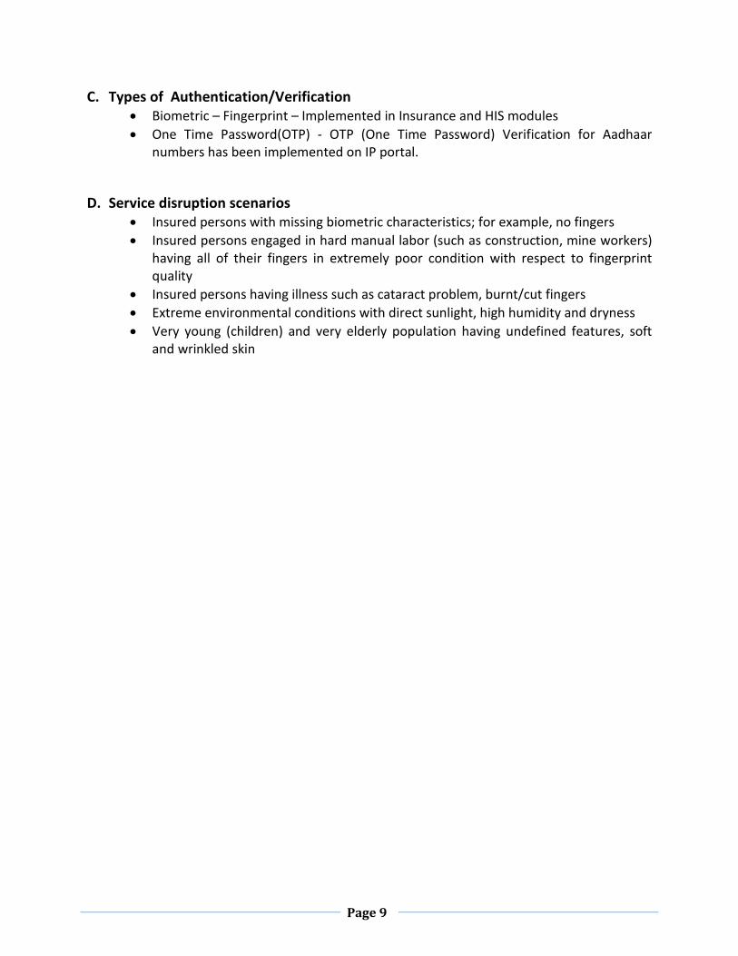
C. Types of Authentication/Verification • Biometric – Fingerprint – Implemented in Insurance and HIS modules • One Time Password(OTP) - OTP (One Time Password) Verification for Aadhaar
numbers has been implemented on IP portal.
D. Service disruption scenarios • Insured persons with missing biometric characteristics; for example, no fingers • Insured persons engaged in hard manual labor (such as construction, mine workers)
having all of their fingers in extremely poor condition with respect to fingerprint quality
• Insured persons having illness such as cataract problem, burnt/cut fingers • Extreme environmental conditions with direct sunlight, high humidity and dryness • Very young (children) and very elderly population having undefined features, soft
and wrinkled skin

Page 10
System Architecture

Page 11
E. Aadhaar Authentication Ecosystem
F. ESIC (Sub AUA) services Authentication request is prepared based on the latest API published by UIDAI using inputs from ESIC (sub-AUA) biometric devices
Once the data is received in the CDAC (AUA) server from ESIC (sub-AUA), CDAC needs to do the following:
• Validate the input data to ensure compliance to Aadhaar data definitions as well as to eliminate issues such as SQL-injection etc.
• After validation, format it to an XML format complying with Aadhaar API specifications • Sign it digitally • Routing authentication request to CDAC (ASA) using appropriate protocol supported by
CDAC (ASA) • Audit Transaction into an audit database.
G. API Protocol Aadhaar authentication service is exposed as stateless service over HTTPS. Usage of open data format in XML and widely used protocol such as HTTP allows easy adoption and deployment of Aadhaar authentication. API 2.0 has been implemented.
H. Biometric Devices Integration ESIC application user interface has a GUI to make provision for biometric devices. It communicates with the biometric device with SDK provided by the biometric device vendor Mantratec.

Page 12
3. Dhanwantri (Health Information System)
ESIC provides social security to Organized Sector Employees who are registered through their Employer. ESIC provides healthcare services to registered employees (called Insured Persons). In Project Panchdeep, the Health Information System is termed as ‘Dhanwantri’ which is single application software designed for all Hospitals, diagnostic centers, Dispensaries in the country under ESIC and ESIS. A. HIS Setup HIS includes total 152 Hospitals and 1286 Dispensaries and they are divided into 6 splits. Each split has clustered database servers of 2 nodes and load balanced application servers of 2 nodes. All clustered database servers are connected to a central storage (SAN). Database servers are installed with MySQL Database Server on /Linux Server; Web Services are deployed on load balanced application servers.
Overall HIS solution is described as below
• Registered employees or their dependents (IP-Insured Person) visit Hospitals or Dispensaries for treatment. On arrival, either of Aadhaar card or e-Pehchan cards is used for the validation of the IP (Insured Person). In some cases, smart card (Pehchan Card) of the IP is also used for this purpose. Only validated IPs are provided medical treatment.
• Clinical Data Repository (CDR) – CDR Database is deployed on clustered database servers with a storage connected to them. Database servers are installed with MySQL Server on Solaris Linux operating system. CDR Web Services are deployed on load balanced application servers.
• During treatment IP's previous clinical data (electronic medical record) is accessed from CDR. At the end of the discharge IP's clinical data is uploaded to CDR. When an IP goes from one hospital/dispensary to another hospital/dispensary his IP identification and verification is done through Insurance solution which is accessible from HIS setup. Clinical data captured at previous hospital/dispensary is available on CDR which is again accessible from HIS setup. Please refer to the Process Flow diagram, it depicts the flow of an IP visiting hospital to receive payment (Claim Process).
• Mobile Application AAA+ has been implemented for booking appointment in Dispensaries. A System which is primarily linked between a patient’s - dispensary would be able to capture and store data giving access to the dispensary to book an appointment slot for that IP/Beneficiary. It includes the ability to reschedule an appointment, cancel an appointment, change mobile number in the Dhanwantri database and seed Aadhaar data.
• In geographical regions where there is no ESIC or ESIS dispensary, IMPs (Insured Medical

Page 13
Practitioner) are empaneled (online or offline) and provide basic health care services to the IPs. There is provision to maintain visit register, certificate issuance, stock register etc. via e-IMP portal.
Process flow

Page 14
B. HIS Architecture
1. High level architecture: Dhanwantri can be accessed from thick desktop client and thin web. IIS Server hosts the Web Services and Web Application including business objects and data access objects. Data Access layer is responsible for all data access connecting to MySQL database server.
Dhanwantri is built on a multi-tier architecture that allows the application to run on multiple servers and at various locations. It is designed based on service-oriented architecture (SOA) which helps to achieve higher level of code re-use, allowing applications to bind to services that evolve and improve over time without requiring modification to the applications that consume them. The architecture comprises of loosely coupled services in distributed transaction environment.
Dhanwantri High level Architecture
2. Service Oriented Architecture - Logical Overview:

Page 15
Dhanwantri SOA Logical Overview
The below given diagram depicts the currently Deployed HIS Architecture and its interfacing at Data Center.
Dhanwatri Deployment diagram

Page 16
C. Hospitals and Dispensaries Desktop PCs at Hospitals and Dispensaries are connected to Data Centre though MPLS cloud to run HIS and CDR solutions installed at Data Centre. Smart card reader, biometrics reader, laboratory equipment interface and IP telephony interfaces are implemented at Hospitals and Dispensaries as required.
Hospital Setup
D. Laboratory Equipment Interface • Laboratory Equipment Interface Engine is deployed on a Desktop PC. Interface Engine
connects to the laboratory equipment through RS232 and it exchanges data with HIS. Above picture depicts Interface Engine connecting to Laboratory Equipment. Laboratory Equipment Interface Engine is capable of connecting in both Uni-Directional and Bi-Directional.
• HO/RO/SRO/DO/B0 • Desktop PCs at HO/RO/SRO/DO/B0 are connected to Data Centre though MPLS cloud to
run Insurance solution installed at Data Centre.

Page 17
4. Pragati (Insurance and ERP) A. Overview ‘Pragati’ consists of a comprehensive suite of bespoke application modules. The key ones are given below:
Note: This suite of bespoke applications [except Insurance] are collectively also named as “ERP” in ESIC system
• Insurance (Registration/Revenue/Recovery/Benefit) • Finance & Account • Human Resources Management Systems • Material Management • Other ancillary modules
The suite of applications is a web-based solution to enable users from various ESIC offices to access the applications from Mozilla, IE (with limitations) web browsers. The solution is driven by a flexible and configurable workflow engine to ensure it meets all workflow requirements of Pragati. Further, a comprehensive Administration Console help the administrator to manage employee details, department details, Roles, responsibilities, Privileges, Process definitions etc. based on the role assigned. The solution also consists of an employee self-service portal which provides the users with GUI from which he can perform multiple tasks such as, changing passwords, checking personalized information, sending messages, receiving corporate notices, participating in group messages etc. Insurance solution is developed on .Net framework and rest ERP modules are developed using Java platform. The modules in the solution integrate seamlessly with all other modules on the ESIC solution and across all necessary departments. Similarly, all the modules are integrated with one another based on the rules and regulations of the organization thus eliminating physical movement of information and increasing speed and efficiency of operations. The solution specifically uses the same / similar forms, registers, & formats so as to enable these organizations to easily transit into an automated environment. The solution incorporates the government rules and procedures so that, it ensures conformity to the stipulated guidelines. The solution ensures update of corresponding files and registers online, thereby eliminating the manual processes. The Solution has all the above features to decrease the processing time and increasing the operating efficiency.
Solution Highlights
• Complete web enable solution

Page 18
• Seamless integration with internal modules as well other external systems • Inbuilt configurable rules engine • Embedded Government of India rules and regulations pertaining to the different modules in the solution • Flexible and configurable workflow engine to handle complex workflows including multi-level hierarchical workflows • Integrated work desk to notify and track work-items pending with any particular employee
B. Insurance (Registration/Revenue/Recovery/Benefit) The modules are designed to accomplish the task of registering the employees, providing benefit by protecting the ‘employees’ in the organized sector against the hazards of accident, sickness, maternity, disablement and death due to employment injury and to validate the eligibility to provide medical care to the insured employees and their families. (Insured persons are known as IPs). It enables full medical care to the registered employees during the period of his incapacity for restoration of his health and working capacity. It enables financial assistance to compensate the loss of his/her wages during the period of his abstention from work due to sickness, maternity, and employment injury. Insurance Setup: Insurance Database is deployed on clustered database servers with a storage connected to them. Database servers are installed with MySQL database Server on Linux server operating system. Insurance Web Services are deployed on load balanced application servers. Application servers are installed with IIS. Insurance Solution:
• Insurance solution has all the employers and employer's employee data. Whenever new employee is covered under ESIC, the employee is registered and an “e-Pehchan” Card is issued. Apart from employee, his/her eligible dependents also get registered to avail ESIC coverage.
• Monthly contribution of all the employees are received from employers and updated in the system.
• Registered employees (IP) submit their claims (if any) for re-imbursement of their wages after discharging from the hospital. These claims are processed in Insurance solution where the required clinical information is accessed from HIS. Processed claims are advised for payment in ERP.
C. Finance & Accounts The finance & accounts modules include the complete Workflow of all finance modules starting from the application or initiation of an activity through various approvals, concurrences, and ratifications till the final closure of this particular activity. The accounting system is based on the Government’s Double Entry based Accrual system.

Page 19
The Financials Accounting system comprises of following core modules – Accounts Payable, Accounts Receivable and General Ledger. The financial accounting system tracks & records the financial transactions arising from different functionalities of the ERP system. The current system includes the following modules:
i. Accounts Payables • Bill Processing • FVC- General • FVC- Interest • Cheque Writing • Cancel Cheque • Replace Cheque
ii. Accounts Receivables • Receipts
iii. General Accounting • Chart of Accounts [Budget Architecture] • Budget Estimation • Budget Allocation • Ledger Posting • Bank / cash payment & receipts vouchers • Journal [Transfer] Entry • Bank Credit/Debit Note • Cash Book • Bank Book • Reconciliation • Trial Balance • Final Accounts [Income & Expenditure Statement, Balance Sheet]
D. Human Resources Management System The Human Resource Management System is made up of Central modules and Vital Components (Payroll, Pension, Leave, Salary & Compensation) that are integrated, and web enabled. The solution includes the complete Workflow of all these modules starting from the application or initiation of an activity through various approvals, concurrences, and ratifications till the final closure of every particular activity. Each of these modules has different steps / activities through which an application/File moves through. At each step, there is a particular form or a particular field in a form that is entered. This has been taken care in the software. All the calculations, Formula's, rules & regulations are largely in conformance to Government Rules and Regulations, but are flexible to handle exceptions and changes according to the requirements.

Page 20
The uniqueness of the solution is that, it is comprehensively integrated to ensure flow of information across modules. E.g. Leave is integrated with Payroll, Promotions, Increments and Pension to integrate the information of non-qualifying leave with these modules. This way all the modules are tightly integrated with one another to allow required information to flow across these modules and thus eliminates redundancy of data. 7th CPC Rules has been implemented (updated from 6th CPC) in ERP application. Note that allowances that has been adopted by ESIC till Jun. 2018 has been implemented in system. Any changes in announced allowances after mentioned period is not yet part of the system. E. Material Management The solution includes the complete workflow of all these modules starting from the application or initiation of an activity through various approvals, concurrences, and ratifications till the final closure of a particular activity. The module incorporates similar forms, OMs, registers and other formats that are in use at a Government organization today. This means that the employees have a fast learning curve in learning and using the solution. Each of these modules have a number of different steps /activities through which an application / File moves through. At each step, there is a particular form or a particular field in a form that is entered. This has been taken care in the software. All the calculations, Formulae, rules & regulations are largely in conformance to Central Government Rules and Regulations, but are flexible to handle exceptions and changes according to requirements. Many procedural rules have been incorporated in order to adhere to the regulations of the Indian Government. Integration with all the departments from which indents originate & the SPCs, allows technical scrutiny by the indenter and approval by the SPC I or SPC II as the case may be. Further, integration of procurement module with the bills & accounts section enable payment & tracking of payments made. This way all the modules are tightly integrated with one another to allow required information to flow across these modules and thus eliminates redundancy of data. The Stores & Procurement module automates the Purchase activities starting from raising an indent all the way to making the payment and closing the file. The following sections give an overview of the features of the modules in current solution.
i. Stores & Inventory: • Material Inwardly [Goods Receipt Note] • SDN [Material Issue] • Material Return • Material Write-off • Auctioning • Fixed Asset Management
ii. Purchase: • Indent • Process Indent • PO (Create/Amend/short-close)
Page 21
• Invoice It covers medical and non-medical part of material management.
F. Other Ancillary Modules It comprises of other modules which are required to maintain ESIC operations like Library, Audit, Legal, PG, RTI etc.
5. Milap (Networking and Bandwidth)
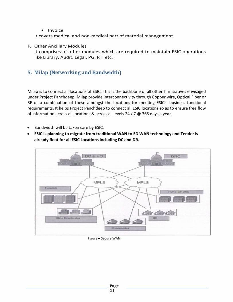
Milap is to connect all locations of ESIC. This is the backbone of all other IT initiatives envisaged under Project Panchdeep. Milap provide interconnectivity through Copper wire, Optical Fiber or RF or a combination of these amongst the locations for meeting ESIC’s business functional requirements. It helps Project Panchdeep to connect all ESIC locations so as to ensure free flow of information across all locations & across all levels 24 / 7 @ 365 days a year. • Bandwidth will be taken care by ESIC. • ESIC is planning to migrate from traditional WAN to SD WAN technology and Tender is
already float for all ESIC Locations including DC and DR.
Figure – Secure WAN

Page 22
ESIC Data & Disaster Recovery Center host all mission critical applications which require high availability and best performing optimized network for end to end fast and secure success. Following components installed at DC/DR:-
Cisco 7600 Series Core Router, 6500 series Core Switch, Storage Area Network, Cisco ASA 5500 Series Firewall, WAE-7300-SERIES Wan Optimizer, Radware IPS, Link Load Balancer, Content Inspection Director, Cisco Unified Call Manager, Polycom/Cisco V.C, etc. are used at DC & DR whereas at locations 2800 & 3800 series Routers are used.

Page 23
6. PASHAN (DC- DR Infrastructure and Location Router)
For Panchdeep implementation and hosting the business applications, , ESI has a scalable Data Centre (with server of adequate capacity and adequate configuration) in New Delhi and a DR Centre in Hyderabad. Pashan broadly covers IT infrastructure for ESIC DC/DR and Locations Router. The key components of Pashan are detailed below:
A. Hardware: Servers, Storage, Tape Library
Server: Currently Cisco UCS 5100 Series servers are being used at DC &DR
Storage: The VNX 5400 EMC VNX is implemented in a modular architecture that integrates hardware components for block, file and object with concurrent support for native NAS, iSCSI, fibre channel and FCoE protocols. The series delivers file (NAS) functionality via two to eight data movers and block (iSCSI, FCoE and FC) storage via dual storage processor leveraging with SAS disk drive technology.
SAN Switches: EMC DS5300 Connectix SAN Switch is deployed with 80 universal ports (48-ports base with 32-port incremental) for SAN connectivity at the primary site with a switch level redundancy. At the DR side a similar set of switches have been offered but with 48 ports. This is because the number of servers with SAN connectivity at the DR site is lower.
Tape Library: Currently Quantum Scalar i500 Tape Library is being used at DC & DR for data backup.
Virtualization : Redhat, Oracle and Microsoft VM’s are deployed in DC & DR. The application have been virtualized.
System software: OS (Red hat and Windows Based), Database (My SQL), Middleware (Glassfish), Mailing solution (currently in the process of migration to NIC data center)
EMC Networker Backup software: For backup EMC networker backup software has been provided and is being used to automate the backup process and backups are also taken on tape library as per the backup schedule and policy. EMC Networker backup and recovery software centralizes, automates, and accelerates data protection across IT environment.
B. Network This section includes Routers, Switches, WAAS, Link Load Balancers, FIBRE interconnect, Server Load Balancers, IP Telephony and Video conferencing.

Page 24
Router: Routers in redundancy are positioned at DC & DR. One router is positioned at all other locations to connect to DC & DR.The Core Router is placed at edge of DC &DR, which provides connectivity to the backbone network, either on multiple Ch-STM1 or Gigabit Ethernet connectivity. Current network architecture comprises of Cisco 7600 Series router as core router aggregating all overlay Secured VPN (GRE with IPSEC/GET/DMVPN) tunnels between Data Center and Remote ESIC offices (RO/BO).
Core Switch: Core Switches are positioned at a DC & DR in HA mode. ESIC has deployed Cisco catalyst 6509 with supervisor 720 processor module as Data Center core switch.
The high switching rate, large switch fabric and 10 GigE densities make the 6509 ideal for this layer. Data Center core is interconnected in DC & DR in redundant Fashion with layer 3, 10GigE links to cisco fabric interconnect, which extends the 10G connectivity to UCS environment.
WAAS: The Cisco Wide Area Application Services (WAAS) and Wide Application Engine (WAE) solution is current acceleration device for DC DR Replication traffic in ESIC network. It is designed to allow ESIC to consolidate their storage, and backup infrastructure into Data Centers while preserving local application network (LAN)-performance as well as current network and security infrastructure.
Link Load Balancers: Link load balancers are provisioned for both internet and intranet links for even distribution of load and high availability of these links. Link Proof ensures effective inbound and outbound load balancing of all the links and traffic switch over to any available link in case of link failure/router failure using multiple health check algorithm and full path health monitoring. This ensures complete link availability. This automated switch over is transparent to the user.
Server Load Balancers: Server load balancers are deployed at public, DMZ and internal MZ zones to distribute the load across multiple servers and provide high availability of servers and services
Call Control or IP-PBX Telephony: Cisco Unified Communication solution is being used to provide integrated telephony solution for IP Phones, gateways over IP architecture using ESIC IP network backbone. The objective for the architecture is to design the highly resilient and available Unified IP communication setup.

Page 25
Figure - IP Telephony Architecture
Video Conferencing:
Cisco Video conferencing solution is deployed at DC to provide the Video conferencing services across 230 locations on PAN India basis. The remote locations have Polycom VSX 7000 endpoints installed for VC purpose. The equipment installed at DC for video conferencing are:
1. MCU- MSE 8000 2. VCS-C 3. Conductor 4. TMS 5. TMS DB
The existing setup of Video Conferencing is given below:

Page 26
Telepresence Management suite application is utilized for scheduling and managing the conference. All the VC endpoints including the MCU and conductor are registered with Cisco VCS-C which provides the gatekeeper functionality in the existing setup. URI based dialing scheme has been implemented and followed to conduct the video conferencing. Cisco Conductor is managing the Telepresence servers installed in MSE 8000 chasse. The existing video conferencing facility is running on the internal MPLS WAN environment.
C. Network Security The security infrastructure components are - Perimeter Firewall (Internet& Intranet), Server Farm Firewall, Network analysis, Network/Host based IPS, AAA server, Network admission control and Correlation and Monitoring response system Gateway, Antivirus & Antispam and SSL Off-loaders. In addition, Bluecoat is used for SSL visibility, malware analysis and security analytics. Nexpose Vulnerability Assessment tool is deployed to assess the vulnerability inside the DC & DR periodically.
i. Tiered Access Control The current Data Center security solution offers multiple configuration points for access control lists (ACLs) for simplified ACL management and scalability. The Data Center aggregation layer is a Catalyst 6500 with a firewall service blade. This allows several filtering points for both client-to-server traffic and server-to-server traffic.

Page 27
ii. Firewall 2 layers of firewalls are deployed to provide comprehensive security to the ESIC datacenter. Cisco ASA 5585 is a purpose-built solution that combine best-of-breed security and VPN services with the innovative Cisco Adaptive Identification and Mitigation (AIM) architecture.
iii. Server Farm protection Firewall To provide server farm security by segmenting servers in multiple firewall protected zones current architecture uses Cisco Firewall Services module in Core Switch i.e. Cisco catalyst 6509. It is used to place servers in different Layer 2 domains or virtual LANs (VLANs), and to separate those VLANs using firewall module.
iv. Security information and event management HPE’s ArcSight ESM collects security log data from an enterprise’s security technologies, operation system, application and other log sources, and analyses that data for signs of compromise, attacks or other malicious activity. If something malicious is detected, the product acts accordingly by generating alert to security administrator or initiating and automated response to stop the malicious activity.
v. AAA System Cisco Secure Access Control Server (ACS) is an access policy control platform that helps to comply with growing regulatory and corporate requirements.
D. Mail Messaging
Mail and Messaging services are recently migrated to NIC. However the old Mail & Messaging server is still functional, After complete migration and
successful running of mail messaging hosted at NIC, the existing mail messaging services hosted in ESIC DC will be phased out.
Old Mail & Messaging Deployment Architecture hosted at ESIC DC:
For Mail and Messaging Java Mail messaging system is in use. Some of the features are:
• Java System Messaging Server • Java System Calendar Server • Java System Instant Messaging • Java System Connector for Microsoft Outlook • Convergence
Following diagram illustrates a sample deployment diagram for the Mail and Messaging Infrastructure.

Page 28
Figure — Mail & Messaging
The messaging system along with collaboration is a standards-based SMTP/POP/IMAP mail server that offers a full range of mail server functionality. The messaging solution is designed to manage the email needs of any number of individual users and comes complete with a powerful set of integrated tools for managing mail accounts and message formats. It also offers a scalable SMTP, POP3, and IMAP4 mail server complete with LDAP and Active Directory support, an integrated browser-based email client, content filtering, spam filters, extensive security features, and more.
E. Enterprise Management System
The ESIC Data Centre site is designed with an understanding that the main services & operations to users is available at the very critical time. ESIC has setup Enterprise

Page 29
Management infrastructure to enhance the application and infrastructure performance. It includes EMS, NMS and HP Arcsight.
EMS provide following feature:-
• Central Monitoring and Management of ESIC Network infrastructure and Application • Graphical views of various entities like IP Segments, Critical Routers & Switches etc. • Real-Time Topology Views • Support for IP based Protocols • Support SNMP communication standards • Real-Time and Historical Data analysis • Ability to receive alarms from third-party tools • Ability to receive data from any SNMP Compatible device and element management
tools • Event Correlation, Log Collection etc.
Following are the integrations involved in the solution:-
• Server Management with Service Desk Management for automatic ticket logging • Network Management with Server Management • Performance Management with Network Management • Desktop Management with Service Desk Management for maintaining assets in CMDB

Page 30
Figure — EMS
Figure — Physical Architecture
i. Server Management The solution is deployed centrally at Datacenter and monitor Servers. It deploys intelligent agents for managing various servers, hardware, operating systems, web servers and databases.
Agents are deployed using RPC DCE for secured communication protocol between the managed server and the management server. Database Management for Oracle/SQL is deployed to manage the oracle /SQL databases. As part of the solution, OS, Oracle/SQL, Web server SPI are deployed on managed servers. Server is deployed on RedHat virtualization cluster to maintain the higher availability.
ii. Network Management It is done using HP Network Node Manager. Network Management software is deployed to manage ESIC network devices. This software monitors using SNMP communication between the managed node and the management station. It is configured to discover & monitor 5500Network Devices in a distributed architecture. Master server is installed with at central location. All devices in central location & around are monitored by this master server. NNM

Page 31
server is installed in DC and DRC, which periodically polls all configured network devices using SNMP.
• Link availability of network elements • Discovery of Network • Real Time Bandwidth Utilization • Topology creation
iii. Application Performance Management It is done using HP Performance Insight. Performance Manager is deployed to collect performance data from agents and SPI's developed on each managed node and network devices. Many out of box reports are available for each type of application being managed. Performance Management is deployed for Network Infrastructure performance and capacity planning.
It provides:
• Infrastructure Management Reports • Capacity Planning • Historical Trending Reports • Predictive Reports of Network and Servers
F. Network Operation Centre/ Security Operation Centre (NOC/SOC) ESIC has centralized NOC & SOC with access restriction placed in ESIC datacenter 2nd Floor. It is in place for proactive monitoring to ensure the maximum availability of services to the end users and to cater the security information and event management. It comprises of the following:-
• Video wall with switcher. • Network topology monitoring and alerting. • Server monitoring. • Blue coat security analysis, Malware analysis and solera. • HP ArcSight SIEM tool

Page 32
G. Data Center Zones
i. DMZ (De Militarized Zone)
De Militarized Zone consist of the traffic that passes through different security checks
• Firewalls • IPS • Anti-Virus & Antispam Servers • After proper scanning this traffic is sent for authentication in secured zone

Page 33
ii. Authentication Zone
Figure 35 — Authentication Zone
• Authentication zone is created as a separated zone on secured layer of core switch behind firewall
• All the traffic has to pass through authentication servers before entering secured militarized zone.
• LDAP servers are used for authentication of traffic. • LDAP servers are configured as primary & secondary server to provide high
availability. • Traffic is allowed to access application only once it is authenticated

Page 34
iii. Management Zone The zone caters to the management of ESIC IT Infrastructure. EMS & NMS suite are positioned here
• This is most secured zone, only trusted traffic can enter this zone • Internet users have to pass through firewall & IPS defense before getting access to
this zone. • Core application servers are places in MZ zone • Main Database server farm is placed here with connectivity option to fiber channel. • Centralized storage is also a part of this zone. • SAN is configured in HA mode. • Centralized backup library & backup is also placed in this zone.
All the packets is scanned, filtered & authenticated before forwarding to application servers in secured Militarized zone.

Page 35
H. Building Management System (BMS)
i. DC-DR building overview
Centralized architecture, Consolidation, Security, Reliability and Availability are the most important parameters in Data Center facility design. Factors like redundancy, simplicity, flexibility and manageability are given importance for Operation and maintenance of the Data Centre & DR Site A centralized infrastructure setup is deployed at Delhi Data Center to host the application. All the users connect to this Data Center through ESIC network. Data Center area is a three floor building where Data Centre is located on ground floor, service-desk is located on first floor, and NOC/SOC is setup on second floor. Data Center building meets the point load and distributed load requirement of the equipment's (Servers racks, Fire suppression cylinders, Main electrical panel, and Air Handling unit).
Access: The current Data Center facility have provision of Single door of dimension2100 mm x 1200 mm for equipment like Air conditioning units, electrical panel etc into the Data Center. The access is adequate from the loading dock, and other support area entrances. It has appropriate door sizes and negotiable corners, ramps and smooth floor surfaces inside the facility. The access pathway to the Data Center is 3'wide with the extension of the boundary wall of the Data Center. Workstations area is separate for easy movement of the equipment's into the Data Center. In addition, proper access is provided in support areas to allow for service or replacement of UPS, chillers and other large items. The door is kept closed and is not be used for regular access of Data Center facility.
A DR site is also at Hyderabad in high availability.
ii. Power Sub System Primary Power distribution [GRID]:
The Power subsystem is a very vital element for the Un-interrupted operation of the Data Center.
Design Considerations:
The primary power distribution for the Servers, Telco Equipment's, Fire Detection/suppression system, building access control, CCTV housed in the Data Center is from the dedicated UPS.
Raw power Lighting Distribution Boards
The LDB's for raw power lighting and Emergency lighting are located in the corridor in the wing is labeled as LDBX. Raw power lighting distribution is drawn from LDB. Circuits are available in the current Data Center area. For additional circuit requirement, spare MCB's in the LDBY is

Page 36
made use for DC expansions. Emergency lighting distribution for the Data Center area and the access path is from ELDZ.
iii. Lighting Normal Lighting: Evenly distributed lighting of 500 LUX illumination is deployed for the datacenter. Mirror Optics low glare light fittings are provided to achieve desired illumination level.
Emergency Lighting: The lighting inside Data Center is connected to raw power supply from LDB9 and LDB1D and 40% of them are connected to the emergency lighting distribution circuit at ELDB. The emergency lights are located at the NOC area, mains control panel areas and passages leading to the main entrance and emergency exit.
Wiring: All the servers racks are individually wired through 3 core 4 sq.mm FRLS PVC copper conductor cable. Panic push button is provided at suitable location to cut off the supply in case of emergency.
Main LT Panel: The panels are designed with electrical draw out circuit breaker and MCCB integrated with genet. All the feeders are provided with necessary safety relay and KWH meter for power consumed by the individual feeder. The panels have supply from two sources, so that the supply could be made available within 2/3 minute in case of failure of mechanical equipment with safety device. Maintenance work on this panel can be carried out without interruption of supply.
Main LT panel distributes raw power to the Data Center facilities. The main LT panel is suitable for 3-Ph, 4-wire power distribution. The Main LT panel feeds power to the UPS input panel, Precision Air Conditioning Panel, and lighting circuits of the Data Center.
iv. Earthing Earth pits location for the current Data Center is in front of the DC building at a distance of approximately 3 meters. A Dedicated ground wire is provided for the Computer equipment in the Data Center.
v. Un-Interruptible Power Supply An Uninterruptible Power Supply (UPS) is installed to carry: n 100% of the computer hardware load for a period at least long enough to transfer the equipment to an alternate utility feed or back-up generator. On-line UPS that runs continuously is used as opposed to an off-line unit. The on-line UPS filters, conditions, and regulates the power. Battery back-up is capable of maintaining the critical load of the room for a minimum of 30 minutes during a power failure to allow for the transfer of power to an alternate feed or generator.

Page 37
vi. Air Conditioning System Precision ACs is provided in the Data Center. The units are Independent and are neither utilized for, nor associated with the overall Building Unit. Floor insulation is carried out using arm flex make insulation of 20 mm thickness. This is required in order to prevent sweating in the floor below. The equipment placement in the racks is such that the cool air intake is from the front and hot air exhaust is from the rear/top of the racks.
vii. Fire Detection System Fire Detection system is a First Hand safety Tool to detect the fire if present and raise an Alarm so as to initiate action. The Detection system uses the following components and devices:
Ionization Smoke Detector: Used for sensing smokes from non-smoldering fires (Thin Smokes) such as arising from combustion of Paper / Cotton / plastics.
Photo Electric Smoke Detector: Used for sensing smokes from smoldering fires (Thick smokes) such as arising from combustion of rubber / PVC cables etc.
Heat Detectors: It is used for sensing the change in the temperature of the hazard, thus signaling a fire condition.
Manual Call Points: Used for Manual Signal to the system of a fire condition.
Manual Abort: Only inhibit discharge of suppression system when operated
Manual Release Station: Manually discharges the suppression system when in conjunction with Fire alarm panel.
Isolator Modules: Used for Segregating 2 separate zones in a given detection loop.
Relay Output Device (Control Modules): Used to Address as well as drive a NC Contact.
Hooter: Used for generating an Audio Alarm in case of a fire situation at output 86-90dBA.
Fire Alarm Panel (FAP): control unit with modules to integrate with various building facilities.
Conventional Fire Detection System: In this type of detection system all the detectors are connected in series to a Main Fire Alarm Panel.
Analog addressable System: Unlike conventional alarm methods, these systems monitor and control the capabilities of each alarm initiating and signalling device through microprocessors and system software. In effect, each intelligent fire alarm system is a small computer overseeing and operating a series of input and output devices.
Fire Suppression System: For Mission Critical DATA Centres, Fire Detection is not the complete

Page 38
solution for Fire Protection. In case of a fire presence immediate action has to be initiated so as to avoid the impetus of a potential Fire Hazard and most important to maintain Business Continuity.
viii. Access Control System Security locking system is provided at the entrance of the Data Center. Electric door lock of the main entrance is capable of manual operation under all conditions.
• Burglar alarm is provided at the emergency exit. • 24-hour security services to the premises • Maintain updated lists of personnel who has been authorized to enter the datacenter • Maintain logs/records for visitors • Visitors or service personnel are well identified and escorted in the Data Center • Permission for staying in Data Center is granted on job basis only. • Backup power is provided for locking control system, security system, fire detection and
suppression system.
The Access Control System control and monitor the access of the personnel entering the Data Center area. Only authorized personnel with relevant access level are allowed to enter the Data Center area. Access Control is computerized control over entry to any area that can be secured with a lock and key. Entry is only allowed to authorized people at authorized times. Control of who is allowed to come and go is easily maintained.
Magnetic Card Reader The current Magnetic card reader installed is used for the current datacenter with magnetic swipe control, each person possess an ID card, which permit access to protected areas at authorized times. The card access system is linked to a microcomputer based system controller, which allows or denies access.
Biometrics The second or higher levels of access control can be achieved using the Biometric devices - Thumb Reader is installed at DC and DR Locations.
ix. Closed Circuit Television (Surveillance System) Design considerations
CCTV system exists with camera installed at Data Center Main door and at entrance and exits doors of the building. Total 30 CCTV including one colour camera at the Datacenter main entrance are deployed inside the DC premises and same is deployed at DRC. The monitor is located in the security room. It is monitored round the clock by the security personnel.

Page 39
x. Local Area Network Design for DC/DR The Local Area Network setup for Data Center has been designed in accordance with the Structured Cabling guidelines for Data and Voice connectivity. The High Bandwidth Data connectivity has been provided to the Servers in the Server Farm and the NOC area. The voice connectivity also has been provided in the Server Farm area and the NOC area in the Data Center for the intercommunication purpose. The WAN links are assumed to be available in the current communication room. All the components used in the LAN setup are Giga speed and Fibre.
I. ITSM and ITIL processes for DC-DR
Scope & Deliverable under ITSM and ITIL are:
• Backup and Restore Management
• Mail and Messaging Management Services
• Security Management Services
• Storage Management Services
• Network Management Services
• Incident & Problem Management
• Configuration Management
• Configuration Backup & Recovery Drills
• Capacity & Availability Management
• Database Management Services
• Incident & Problem Management
• Application Monitoring Services
• Software Distribution / Patch Management Services
• IP PBX Management Services
• Go-live Support Service Delivery Process

Page 40
7. Overall Panchdeep Architecture
A. Technical Architecture The architecture below depicts the Overall Solution Architecture for Panchdeep project. It is layered technology solution with clear segregation of Healthcare, ERP, Data Analysis, Messaging and Collaboration components of the solution. This solution is based on ORACLE Stack with WebLogic Application Server, ORACLE SOA Server forming the middleware layer. SAS constitutes of ETL and Data analysis and Reporting utility. MySQL RDBMS provides persistence layer for structured data. SAS provides the analysis, search & mining capabilities. Additionally, Digital Signature has been implemented across the modules for authentication and authorization of information. The approach of solution stack selection is based on "best-of-breed" components and products in the industry. Advantage of this approach is the ability of the solution architecture to adapt itself to whatever solutions / products are chosen at each layer independent of the other layers. Every piece of ESIC's business requirement has been mapped into one or more components in solution architecture based on the reference architecture.
Overall Technical Architecture

Page 41
Portal Architecture
The Current architecture comprises of following broad technology components:
• Client Layer: The Client layer contains the devices that interact with Portal • Browser – This is a traditional Internet browser that initiates requests to the Web
Server and displays the results of requests. Users access the portal using internet browsers; the content is personalized for registered users. Content Authors have access to publishing site both internally and through the internet.
• DMZ Zone Layer: This is the layer hosting the edge servers, external DNS, SMTP relay services, front-end Web Servers & Presentation Services.
• Load Balancer – This is the hardware load balancer that ensures that load is distributed evenly across all of the web server instances.
• Directory Services – The Directory services is provided through LDirectory Server ODSEE (Oracle Directory Server Enterprise Edition) and Oracle OAM (Oracle Access Manager). ODSEE Directory Server holds the user credentials for all users including the internal authors & content publishers.
• Web Front End Server - This is a traditional web server that serves the content or forwards requests to the Application Server. Web Server takes the request and recognizes that the requested resource is on the application server, and, using the Web server plug-in, redirects the request to the Application Servers

Page 42
• Application server – The various custom-built applications is deployed on the
application server. • Integration server - The application integration services provide a composite
platform optimized for building service-oriented applications that extend and integrate into ESIC’s the custom-built application infrastructure as well as the ERP applications. Java CAPS is used for the same.
• Mail Server –The messaging system along with collaboration is a standards-based SMTP/POP/IMAP mail server that offers a full range of mail server functionality. The messaging solution is designed to manage the email needs of any number of individual users and comes complete with a powerful set of integrated tools for managing mail accounts and message formats. It also offers a scalable SMTP, POP3, and IMAP4 mail server complete with LDAP and Active Directory support, an integrated browser-based email client, content filtering, spam filters, extensive security features, and more. Backup & Restore of Data: The infrastructure use structured back & restores solution to provide resilience to the entire infrastructure.
B. ESIC Web and Liferay Portal Portal complies with SOA approaches and uses service oriented concepts, leverages Web services extensively and leverages portlets, which consume services or communicate to provide seamless integration of applications. User interface Services provide the capabilities required to deliver ESIC IT functions and data to end users, meeting the end-user's specific usage preferences. Interaction services provide the portal view of ESIC applications as a simple, unified access point to applications. ESIC portal solution provides users with convenient access for day to day functions in a secure manner. Portals provide an extensible framework for interacting with enterprise ESIC applications, content, people, and processes. The Portal provides additional services such as single sign-on, security, document management, web content publishing, search, personalization, collaboration services, enterprise application integration, support for mobile devices, and site analytics LIFERAY Portal server provides features like personalization, aggregation, integration with various back-ends out of the box. The Portal server is used for both Intranet and Internet based portals. The Sequence Read Archive (SRA) is used for accessing the back-end resources of ESIC securely from the portal. The LIFERAY Portal server is deployed both vertically (by adding more portal instances in a server) or horizontally (by having more servers) to achieve scalability. The LIFERAY Portal Server provides identity-based content delivery, as per ESIC's requirements, which enables enterprises to define portal pages and provide users with access to content specific to organizations, sub-organizations, roles, and even user-defined communities.
The Identity-based capabilities of the LIFERAY System Portal Server, as per ESIC's requirements include:

Page 43
• Web single sign-on (SSO) for secure login to the portal and all applications accessed through the portal, as well as across multiple portals for portal federation
• Flexible authentication (can support multiple authentication schemes like LDAP, UNIX, NIS, RADIUS and x.509 digital certificates) and authorization services for changing and complex business environments.
• Fine-grained policy rules so that multiple authentication mechanisms is chained together to provide additional flexibility and integration of legacy systems
• Secure SSL based Portal server ensures that we have a security enabled portal.
• Delegated admin features to manage Portal server. • There are several Portlets available out of the box, for the most
commonly used functionalities like Email, Blog, and RSS/XML. • The Other important features of portal, which match ESIC's
requirements: o Full text search engine with federated search and taxonomy
capabilities o Extensive community features like built-in wikis, blog support, sharing
files, group calendaring, and communities • The Portlets to be deployed on the LIFERAY Portal server is developed via
NetBeans and deployed remotely to the Sun Portal server after development.
Apart from integrated single user interface infrastructure for the ESIC IT Solution, Liferay and Java CAPS provide following functionality to the ESIC application users:
• Service Oriented Architecture: The Middle tier architecture suggested for the Portal environment is based on well-known open standards based architecture - Service Oriented Architecture. All business capabilities of the ESIC portal such as Hospital Management, ERP, Mail and messaging solution etc. is wrapped around services layer (or SOA). These services are consumed by the frontend ESIC portal.
• Seamless integration with the applications such as Hospital management System, ERP application etc.
• Document Management • Workflow • Records Management • Search • Knowledge Management • Collaboration services • Personalization and team sites • Web Content Management: Liferay CMS provides the facility that enable

Page 44
designated ESIC administrators to have content management feature. The static contents which are hosted out of ESIC portal is kept up-to-date with version control. This is an in-built feature of Liferay which enable this functionality using workflow based approval process. The centrally controlled auditing, expiration & retention policies, archival, retention and regulatory compliance is implemented based on records management feature of Liferay Technologies
• Content Management: The ESIC portal has a robust document management system. This feature is implemented using LIFERAY CMS(Content Management System) Technologies to capture, store, organize, analyze, create and synthesize information; and making available within and across ESIC users. Liferay Document Management captures, shares and retains content, enabling users to version, search and simply build their own content through this tool. The solution provides Integrated DMS functionality like Check-in, Check-out, Version control, Meta tagging, and Administrative Capabilities. Document processing is provided through a series of workflows included like Document Review, Document Approval, Signature Collection, Issue Tracking, and Customer Routing for Review/Approval. The solution provides enhanced document management site templates that are used right away without further customization:
o Managed Document Library site template o Divisional Library site template o Translation Library site template

Page 45
8. ESIC External Interfaces
As per Government of India directions following external interfaces have been developed that interface with ESIC:
A. e-Pehchan (Aadhaar based implementation for verification and authentication) for UIDAI Refer Section 3 (E-Pehchan) of this document
B. Unified Shram Suvidha Portal for MoLE It is web based portal for integrating the Registration of establishments for generation of Labour Index Number (LIN), Reporting of Inspection, submission of returns and Grievance System for Ministry of labour & Employment (MoLE) is under development. This Portal facilitates ease of reporting at one place for various Labour Laws, consolidated information of Labour Inspection and its enforcement. It includes below components –
• Single sign-on for Labour Laws • ECR • Employer Registration • LIN Generation • Inspection Module • Data Consistency due to integration with LIN • Data Sharing across Enforcement Agencies • Email/SMS notifications • Employers/Establishments
Enforcement Agencies involved:
• Ministry of Labor and Employment • Chief Labour Commissioner • EPFO • ESIC
C. E-Biz for DIPP
eBiz project has been implemented for Integration of ESIC Employer Registration service with eBiz portal, these include integration of MCA, PAN, TAN, ESIC and EPFO services. On the basis of the available information, during the registration of the Company on eBiz portal, provisional registration under ESI Act is allotted. The temporary registration number is issued from the application on eBiz on the basis an independent logic/algorithm, there is no sharing of this information with ESIC portal at this stage, whenever user fulfills the criteria for coverage under ESI Act he can fill the information in the Employer Registration

Page 46
Form of ESIC hosted on eBiz portal, the information is pushed to ESIC portal and he is be allotted the final ESIC Code Number through the already integrated service of Employer Registration on eBiz portal. A common registration form of ESIC/EPFO/CLC(C) has been hosted on eBiz. PFO, ESIC with CLC (Contract Labor Act, Inter State Migrant Workmen Act and Building and Construction Worker’s Act) are a part of the composite application form.
D. E-Nivesh for PMO
e-Nivesh is a Single window system for monitoring of setting up business/projects in India.
It aims at operationalizing a transparent, efficient and convenient interface, through which the government and businesses can track the services/clearances incorporated in this portal for time limits at intermediate stages of processing.
This National portal is envisaged to provide the entrepreneur with all requisite information under one umbrella– starting from the establishment of a business, through its ongoing operations, it reduces delays in various regulatory processes.
It also includes Integration of ESIC with E-Nivesh portal for Registration monitoring. ESIC provides count of number of Employers and Insured Persons registered with ESIC post 26 May 2014 .Web API’s have been created to communicate with the e-Nivesh portal for the same.

Page 47

Page 48
9. Enterprise Intelligence (BI) The current Enterprise Intelligence solution is deployed to meet the analytical and business intelligence requirements of the ESIC. Best in class Business Intelligence Solution is put in place to equip ESIC management team with the analytical tool for enhanced decision-making capabilities. Enterprise Intelligence solution included developing an Enterprise Data Warehouse coupled with an interactive Reporting and Analytical application. The application helps ESIC management team to perform the in-depth analysis based on the historical data. The solution consolidates the data from different business functions and provides a single source of truth to the end users for multi-dimensional analysis along various parameters. Solution design ensures the capability of extending further integration of applications in future. Modularity, flexibility and scalability are the key considerations for Enterprise Intelligence solution. Integration - this is one of the key success factors for this solution and features the following:
• Integrated metadata management • Seamless integration with source applications • Integration with other applications like exchange server and MS Office. • Web enablement • Security as per the user requirements
As part of the solution, data warehouse is built to capture the data for analytical analysis for following key business functional areas:
• Health Information System • Finance • Insurance • Inventory • Acturial • Other ERP modules
Overall BI implementation is as below -
A. BI Process - ESIC Logical Data Model • Data Management All the relevant data that is made available by the individual source systems is captured. EDW team does not create or correct any source data. • ETL Process
• Extracting data from the source system as per mutually agreed Data exchange mechanism.
• Design & Implementation of ETL Scripts to load data from source system to staging and finally into the enterprise data warehouse.
• Implementation of Data Quality based on business rules.

Page 49
• Frequency
Daily/Weekly/Bi-Weekly/Monthly/Half Yearly/Yearly
• Backup and version control ETL repository is backed up on daily basis. Any changes in the ETL mapping versions are maintained via SAS version control Repository. • Staging Area Staging area is the intermediate area between the source data and the target EDW. Primarily there are two components of the Staging area.
• Landing / Staging Layer • Data Cleansing and transformation layer
Data is extracted from the source system and loaded into in the landing layer of the staging area without applying any transformation rules. The data quality rules captured during the requirement Phase is applied to transform the source data into the quality to data to be loaded into the EDW. Staging area captures the incremental data on daily basis and not stores any historical data. It is the only point of loading the data into the EDW. Staging area also holds all the temporary tables required for transforming and loading the data from staging to the EDW.
B. BI Architecture BI is installed and configured in the system. Any change in the Current tools or change in the hardware platform or any other requirement may require the installation to be done again.
i. Key Solution Components of implementation • MYSQL Enterprise Edition • SAS® Enterprise Business Intelligence • SAS® Data Integration • Dashboard • Web Report Studio • Enterprise Guide
ii. Solution Architecture Diagram Underlying diagram represents the Current BI architecture.

Page 50
BI Architecture
iii. Approach/Methodology The key factors that determine the final solution approach are:
• Network Load • Availability of source system extraction window • Requirements captured during Requirements Phase • Performance & Overall Time for execution • Audit Trail & Security
C. BI Reports Current Business Intelligence solution involves set of reports that is tracked and analyzed by the ESIC. The current solution helps in increasing the end user productivity and helps the management team in taking better decisions. New reports are continuously added as and when there is a business requirement. Other than these there are various BI Dashboards implemented in the area of HIS, ERP and Insurance.
D. Components of Enterprise Intelligence (SAS) In general, SAS Data Integration Server provides an ability to integrate data from relational databases (RDBMS) and non-relational databases. Currently in ESIC business intelligence module SAS Data Integration Server integrate data from MySQL relational database version 5.7.18. Below are the product offerings of SAS 9.4:
Platform Suite for SAS Quality Knowledge Base Locale, English India SAS Analytics Pro, including the products:
• Base SAS® • SAS/GRAPH® • SAS/STAT

Page 51
• SAS Data Management Contextual Extraction Language Pack for English • SAS Data Management Standard Server • SAS Data Quality Standard, including the products: • SAS® Integration Technologies • SAS Enterprise BI Server • SAS Enterprise Guide • SAS Metadata Bridge for Microsoft Excel • SAS Metadata Bridges for General Industry Standards • SAS Metadata Bridges for Microsoft SQL Server • SAS Metadata Server • SAS/ACCESS Interface to MySQL • SAS/ACCESS Interface to ODBC • SAS/ACCESS Interface to Oracle • SAS/ACCESS Interface to PC Files • SAS/ETS