Embed Size (px)
Citation preview
DATE December 2019
PAGE 1 of 39
Annexes to Realisation Agreement
Annex 0 Definitions used in Annexes
Annex 1 Details of Connected Party and TenneT
Annex 2 Description and technical specifications of the Connection,
including drawings
Annex 3 Technical terms and conditions for the Platform
Annex 4 Technical requirements applicable for the connection of offshore
power park modules
Annex 5 Compliance Activities; applicable testing requirements
Annex 6 Operational arrangements and exchange of information
TenneT TSO B.V.
DATE December 2019
PAGE 2 of 39
Annex 0 Definitions used in Annexes The English terms used is the Annexes are referring to the following Dutch definitions, defined in article 1 of the General Terms and Conditions to the Realisation Agreement and the Connection- and Transmission Agreement.
English Term Definitie
Annex Bijlage Een bijlage bij een van de Overeenkomsten, zoals
van tijd tot tijd gewijzigd.
Agreements Overeenkomsten
De Realisatieovereenkomst en de Aansluit- en
Transportovereenkomst.
Realisation Agreement Realisatieovereenkomst
De tussen TenneT en Aangeslotene gesloten realisatieovereenkomst en de bijlagen daarbij, zoals van tijd tot tijd gewijzigd.
Connected Party Aangeslotene
De aangeslotene zoals omschreven in de Overeenkomsten. Aangeslotene wordt geacht Offshore Power Park Module (Offshore PPM) te zijn zoals bedoeld in RfG.
Connection Aansluiting
Het geheel van kabels en apparatuur op het Platform dat de Installatie verbindt met het Net op zee. De Aansluiting, zoals nader omschreven in Bijlage 2 bij de Realisatieovereenkomst en Bijlage 2 bij de Aansluit- en Transportovereenkomst, maakt deel uit van het Net op zee. De 66 kV kabels van Aangeslotene maken geen deel uit van de Aansluiting.
Platform Platform
Het offshore onderstation van TenneT, het platform waarop de Aansluiting aanwezig is of wordt aangebracht.
Offshore Power Park
Modules
Offshore Power Park Module / Offshore PPM
Een Offshore PPM of elektriciteitsproductie-eenheid als bedoeld in RfG, zoals verder gespecificeerd in Bijlage 4 bij de Realisatieovereenkomst en Bijlage 4 bij de Aansluit- en Transmissieovereenkomst.
Connection Aansluiting Het geheel van kabels en apparatuur op het Platform dat de Installatie verbindt met het Net op zee. De Aansluiting, zoals nader omschreven in Bijlage 2 bij de Realisatieovereenkomst en Bijlage 2 bij de Aansluit- en Transportovereenkomst, maakt deel uit van het Net op zee. De 66 kV kabels van Aangeslotene maken geen deel uit van de Aansluiting.
Connection Point Overdrachtspunt Een fysiek punt dat de interface vormt tussen
enerzijds de Aansluiting en anderzijds de Installatie,
TenneT TSO B.V.
DATE December 2019
PAGE 3 of 39
zoals omschreven in Bijlage 2 bij de
Realisatieovereenkomst en in Bijlage 2 bij de
Aansluit- en Transportovereenkomst.
Primary Connection
Point
Primair Overdrachtspunt
Elk primair Overdrachtspunt zoals omschreven in Bijlage 2 bij de Realisatieovereenkomst en Bijlage 2 bij de Aansluit- en Transportovereenkomst.
Secondary Connection
Point
Secundair Overdrachtspunt
Elk secundair Overdrachtspunt zoals omschreven in Bijlage 2 bij de Realisatieovereenkomst en Bijlage 2 bij de Aansluit- en Transportovereenkomst.
Tertiary Connection
Point
Tertiair Overdrachtspunt
Elk tertiair Overdrachtspunt zoals omschreven in Bijlage 2 bij de Realisatieovereenkomst en Bijlage 2 bij de Aansluit- en Transportovereenkomst.
Acknowledged Metering
Responsible Party
Erkende Meetverantwoordelijke
Een erkende meetverantwoordelijke partij of een
erkend meetbedrijf zoals bedoeld in de Meetcode
Elektriciteit.
Metering Code Codes De door de ACM vastgestelde codes overeenkomstig de Wet, zoals van tijd tot tijd gewijzigd, inclusief:
de technische codes zoals bedoeld in artikel 31, eerste lid van de Wet, dat wil zeggen de Netcode Elektriciteit, de Systeemcode Elektriciteit, de Meetcode Elektriciteit en de Begrippencode Elektriciteit;
de Tarievencode Elektriciteit zoals bedoeld in artikel 36 van de Wet; en
de Informatiecode Elektriciteit en gas zoals bedoeld in artikel 54, eerste lid van de Wet.
Onshore Substation Onshore Onderstation
Het onshore onderstation dat wordt beheerd door
TenneT en waaraan de exportkabels van het
Platform worden verbonden.
RfG Requirements for
Generators (RfG)
De EU Verordening tot vaststelling van een
netwerkcode betreffende eisen voor aansluiting van
electriciteitsproducenten op het net (Requirements
for Generators), die op offshore-power park modules
van toepassing is.
The Parties Partij of Partijen Een partij of de partijen bij een van de
Overeenkomsten, zijnde TenneT en/of Aangeslotene.
TenneT TenneT TenneT TSO B.V.
Feed-in Transmission
Capacity
Transportvermogen
Invoeden
Het contractueel overeengekomen op de Aansluiting beschikbaar gestelde transportvermogen zoals bedoeld in artikel 3.1.1 van de Netcode Elektriciteit dat Aangeslotene mag invoeden op het Net op zee, zoals gespecificeerd in Bijlage 1 bij de Aansluit- en Transportovereenkomst.
Energisation
Operational Notification
EON Een 'Energisation Operational Notification' of inschakel-bedrijfsvoeringsnotificatie afgegeven door TenneT, als bedoeld in RfG.
TenneT TSO B.V.
DATE December 2019
PAGE 4 of 39
(EON)
First Interim
Operational Notification
(ION1)
Refer to: ION
Een 'Interim Operational Notification' of voorlopige bedrijfsvoeringsnotificatie afgegeven door TenneT, als bedoeld in RfG. De ION wordt onderscheiden in ION1 (af te geven door TenneT voor ingebruikname van de eerste turbine) en ION2 (af te geven door TenneT na het bereiken van 60 MW geïnstalleerd productievermogen), zoals beschreven in Bijlage 5 bij de Aansluit- en Transportovereenkomst.
Second Interim
Operational Notification
(ION2)
Refer to: ION Een 'Interim Operational Notification' of voorlopige bedrijfsvoeringsnotificatie afgegeven door TenneT, als bedoeld in RfG. De ION wordt onderscheiden in ION1 (af te geven door TenneT voor ingebruikname van de eerste turbine) en ION2 (af te geven door TenneT na het bereiken van 60 MW geïnstalleerd productievermogen), zoals beschreven in Bijlage 5 bij de Aansluit- en Transportovereenkomst.
Final Operational
Notification (FON)
FON
Een 'Final Operational Notification' of definitieve bedrijfsvoeringsnotificatie afgegeven door TenneT, als bedoeld in RfG.
Connection and
Transmission
Agreement
Aansluit- en
Transportovereenkomst
De tussen TenneT en Aangeslotene afgesloten
Aansluit- en Transportovereenkomst voor een Net op
zee en de Bijlagen daarbij, zoals van tijd tot tijd
gewijzigd.
Contracted
Transmission Capacity
Gecontracteerd Transportvermogen
De gecontracteerde afname van transportvermogen zoals bedoeld in artikel 3.7.4 van de Tarievencode Elektriciteit, waarvan de waarde is gespecificeerd in Bijlage 1 bij de Aansluit- en Transportovereenkomst.
Overplanting Capacity Overplantingscapaciteit Het transportvermogen dat meer bedraagt dan het
Transportvermogen Invoeden.
Tariff sheet Tarievenblad Het tarievenblad waarop ter informatie door
Aangeslotene aan TenneT verschuldigde
gereguleerde tarieven en gereguleerde vergoedingen
staan vermeld.
Working day Werkdag Een werkdag zoals bedoeld in de Begrippencode
Elektriciteit.
WTG WTG Wind Turbine Generator of windturbine.
TenneT TSO B.V.
DATE December 2019
PAGE 5 of 39
Annex 1 Details of Connected Party and TenneT
General details
Connected Party [Name]
Correspondence address [……………………]
Postcode + city/town [……………………]
Chamber of Commerce registration number [……………………]
Invoice address [……………………]
Order number / reference for invoicing purposes [……………………]
Relation managers
Organisation: [……………………]
Department: [……………………]
Contact person: [……………………]
Correspondence address [……………………]
Postal code + city/town [……………………]
Telephone: [……………………]
Fax: [……………………]
E-mail: [……………………]
Organisation: TenneT TSO B.V.
Department: Offshore NL
Contact person: ………………
Correspondence address Utrechtseweg 310
Postal code + city/town Postbus 718, 6800 AS Arnhem
Telephone: ………………
E-mail: ………………
TenneT TSO B.V.
DATE December 2019
PAGE 6 of 39
Management during Realisation
Organisation: [……………………]
Department: [……………………]
Contact person: [……………………]
Correspondence address [……………………]
Postal code + city/town [……………………]
Telephone: [……………………]
Fax: [……………………]
E-mail: [……………………]
Organization: TenneT TSO B.V.
Department: Offshore NL
Contact person: ……………………
Correspondence address Utrechtseweg 310
Postcode + city/town Postbus 718, 6800 AS Arnhem
Telephone: ……………………
E-mail: ……………………
TenneT TSO B.V.
DATE December 2019
PAGE 7 of 39
Annex 2 Description and technical specifications of the Connection, including
drawings
Connection details
Substation (name and coordinates) Platform Hollandse Kust Noord: 587410 E,
5839436 N (in ETRS_1989_UTM_Zone_31N)
Connection capacity Two times 350 MW
Capacity according to permit for exploiting the Installation Two times … MW (maximum 380 MW)
Physically connected voltage level 66 kV
Description of the Connection
Minimum four (4), maximum eight (8) 66 kV strings, connected to maximum six (6) bays, with bay names as
stated below:
Object-ID Object description Voltage level Comment by
Connected Party
HKN Platform Hollandse Kust Noord 220/66 kV n/a
AFA1x t.b.d. (site x) 66 kV
AFA2x t.b.d. (site y) 66 kV
AFA3x t.b.d. (site x) 66 kV
AFA4x t.b.d. (site y) 66 kV
t.b.d. 66 kV
Description of the Connection Points
Primary Connection Point The Primary Connection Point between the Installation
(Offshore Power Park Module) and TenneT is specified at the
66kV cable termination of the 66kV inter-array cables in the
66kV switchgear installation on the Platform.
Secondary Connection Point(s) The Secondary Connection Point(s) are defined at the
terminals of the interface cabinet and it concerns all
communication and control related interfaces.
Tertiary Connection Point(s) The Tertiary Connection Points concern all spatial boundaries
at the Platform and onshore, where ownership and
management transfer to the Parties.
TenneT TSO B.V.
DATE December 2019
PAGE 8 of 39
Explanation of Secondary Connection Points
Current transformer and voltage transformer measurements
The current and voltage measurements shall be provided by TenneT at the terminals of the interface cabinet
located in the Connected Party's room on the platform. The interface cabinet is property of TenneT. From the
terminals of the interface cabinet onward, the Connected Party is responsible for connecting these
measurements to its equipment, including the measurements for the accountable metering equipment of the
Acknowledged Metering Responsible Party. The metering equipment shall be according to the Metering Code.
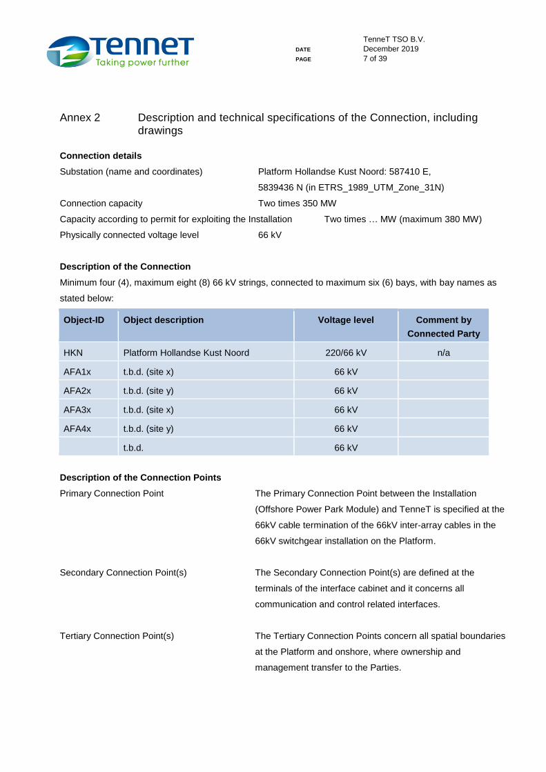
Explanation of fibre optic cable Connection Points (Optical CP) as Secondary Connection Points
TenneT shall install two 220kV export cables from the Onshore Substation to the Platform (offshore). Fibre
optic cables will be included in these cables. All of these fibre optic cables will end in a fibre optic patch panel
which will be installed into a fibre optic patch cabinet in TenneT rooms, both on the Onshore Substation as
well as on the Platform. From the TenneT room designated fibre optic cables will be installed and connected
to a second patch panel which will be installed into a fibre optic patch cabinet in the designated room for the
Connected Party ("Connected Party's room" in the figure below). The optic fibres designated to be used by the
Connected Party will be 1:1 patched in the TenneT rooms and thereby create a "dark fibre" path from the
Connected Party's room onshore to the Connected Party's room offshore (on the Platform).
TenneT shall install the patch cabinet and panel in the Connected Party's room offshore. The patch panel (in
the patch cabinet) placed in the Connected Party's room will be the Optical CP, meaning that the patch cable
itself that will be plugged into the patch panel of the equipment shall be provided and installed by the
Connected Party. Any other communication equipment or cables required by the Connected Party inside the
Connected Party's room shall be provided and installed by the Connected Party.
The above design is depicted in the figure below:
TenneT TSO B.V.
DATE December 2019
PAGE 9 of 39
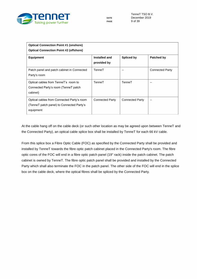
At the cable hang off on the cable deck (or such other location as may be agreed upon between TenneT and
the Connected Party), an optical cable splice box shall be installed by TenneT for each 66 kV cable.
From this splice box a Fibre Optic Cable (FOC) as specified by the Connected Party shall be provided and
installed by TenneT towards the fibre optic patch cabinet placed in the Connected Party's room. The fibre
optic cores of the FOC will end in a fibre optic patch panel (19" rack) inside the patch cabinet. The patch
cabinet is owned by TenneT. The fibre optic patch panel shall be provided and installed by the Connected
Party which shall also terminate the FOC in the patch panel. The other side of the FOC will end in the splice
box on the cable deck, where the optical fibres shall be spliced by the Connected Party.
Optical Connection Point #1 (onshore)
Optical Connection Point #2 (offshore)
Equipment Installed and
provided by
Spliced by Patched by
Patch panel and patch cabinet in Connected
Party's room
TenneT -- Connected Party
Optical cables from TenneT’s room to
Connected Party’s room (TenneT patch
cabinet)
TenneT TenneT --
Optical cables from Connected Party’s room
(TenneT patch panel) to Connected Party’s
equipment
Connected Party Connected Party --
TenneT TSO B.V.
DATE December 2019
PAGE 10 of 39
Also the relevant Tertiary Connection Point (e.g. power supply) is defined at the interface panel in the Connected Party's room.
Optical Connection Point #1 (cable deck)
Optical Connection Point #2 (Connected Party’s room)
Equipment Installed and
provided by
Spliced by Patched by
Splice box on cable deck TenneT -- --
Patch cabinet in Connected Party's room TenneT -- --
Patch panel in Connected Party's room Connected Party -- Connected Party
Optical cables from splice box to Connected
Party’s room (TenneT cabinet panel)
TenneT Connected Party --
Optical cables from Connected Party’s room
(TenneT patch panel) to Connected Party’s
equipment
Connected Party Connected Party --
TenneT TSO B.V.
DATE December 2019
PAGE 11 of 39
Single line diagram and other drawings and/or photographs, including but not limited to the
connection- and metering point(s), bay codes.
The following single line diagrams and other drawings and/or photographs, including but not limited to the
connection- and metering point(s), bay codes, are added to this Annex 2:
A2.1 HV Single Line Diagram (general) (ONL-TTB-04301, v07 dated 16 September 2019)
A2.2 Offshore Grid Connection Scheme (general) (ONL-AMO-00003, v01 dated 15 November 2019, sheet 1
to 4)
A2.3 Layout offshore WPO Control Room (ONL-TTB-00216, dated 14 February 2019)
TenneT TSO B.V.
DATE December 2019
PAGE 12 of 39
Annex 3 Technical terms and conditions for the Platform
1. General system specifications
Nominal frequency: 50 Hz
Nominal voltage: 66 kV +/- 10%
Maximum system voltage: 72,5 kV
Impedance earthed grid with
Short circuit withstand capability of 66 kV GIS: 31,5 kA
Maximum contribution from power transformer: 16 kA
Single phase short circuit current: Maximum 8 kA (maximum 0,6 s)
Earth fault factor (c): approximately 1,4 (according to IEC 1 < c < 1,73)
Operating voltage: 66 kV +/- 1%
2. Number of J-tubes and bays
The Platform will accommodate up to two times 8 (eight) J-tubes (inner diameter 450 mm) for use by the
Connected Party. Each connection of a J-tube will be facilitated with a Primary Connection Point.
Six 66 kV bays will be available per Power Park Module of 350 MW (i.e. the Installation of the Connected
Party and any other Power Park Module connected to the Platform). This results in four bays "one string – one
bay" and two bays "two strings – one bay". In the case of "two strings – one bay", this will be done with two
separate cable disconnectors.
Minimum number of 66 kV cables per Power Park Module (350 MW): 4
Maximum number of 66 kV cables per Power Park Module (350 MW) 8
Maximum number of 66 kV GIS bays available per Power Park Module (350 MW) 6
Maximum current (I) per 66 kV GIS bay: 1250 A
Minimum power (P) per 66 kV GIS bay: 45 MW
TenneT will define the final layout of the 66 kV switchgear installation and cable routing on the Platform in
order to ensure a balanced distribution of power per switchgear section. It shall be possible to group all 66kV
cables of the Connected Party into two times two sections. The maximum active power (P) for each section
shall be less than 210 MW.
3. Secondary Connection Point
The Secondary Connection Point is defined and explained in Annex 2;
A metering system is to be provided by the Acknowledged Metering Responsible Party under
responsibility of the Connected Party;
TenneT TSO B.V.
DATE December 2019
PAGE 13 of 39
Besides a metering system, TenneT will install Power Quality Monitoring equipment to measure and verify
that the energy supplied is in accordance with RfG requirements;
A patch panel in the Connected Party's room will be provided by TenneT facilitating the fibre optic cable
interface which is explained in detail in Annex 2;
An interface cabinet for secondary equipment in the Connected Party's room will be provided by TenneT
in order to facilitate the other Secondary Connection Points, including a telecom interface (other than fibre
optics) and other shared services (such as a weather station, CCTV, etc.).
Connected Party shall ensure that TenneT is not disadvantaged by the use of the fibre optics made
available by TenneT and / or the patch panel and / or patch cabinet (room number: t.b.d.). This means,
among other things, that the Connected Party will not perform or have performed on its behalf any acts
that:
o Allow third parties to use the fibre optics made available by TenneT in any way by subletting or
otherwise;
o Create adjustments in any way at or to the demarcation point of the fiber optic;
o Attempting or actually carrying out (repair) work on the glass fibers, cable, patches or other
equipment involved in this or in any way, or taking measurements, without prior notice to TenneT
and prior written permission for this;
Connected Party reports regular work on the patch panel and / or patch cabinet to the telecommunications
department of TenneT in advance. This notification must be made during working days on +31 (0) 26 373
1616 and via e-mail to [email protected]. In the event that urgent work has to be carried out by
Connected Party to the patch panel and / or patch cabinet, Connected Party will inform the telecom
department of TenneT as soon as possible after the work has started.
If TenneT has to perform regular work involving the fibre optics made available to Connected Party,
TenneT will first consult with Connected Party for a suitable moment. In the event of unforeseen work and
in the event of a malfunction, TenneT will inform Connected Party as soon as possible after the work has
started.
Contrary to the liability regime in the main body of this Agreement, TenneT is not liable for any damage
suffered by Connected Party as a result of the unavailability of the glass fibres or patch panel / patch
cabinet made available by TenneT, unless in case of intent or gross negligence.
4. Tertiary Connection Points
The tertiary Connection Points are defined in Annex 2.
The interface cabinet for secondary equipment in the Connected Party's room shall also facilitate a power
supply comprising two times uninterrupted 400 VAC (16 A) and two times 110 VDC (6 A).
TenneT TSO B.V.
DATE December 2019
PAGE 14 of 39
5. Operation of bays
TenneT will standardise the operation of bays for the Platform. TenneT (National Control Centre, NCC) shall
make the standardised procedure for operation of bays available for the Connected Party and other Offshore
PPMs. The switchgear installation with connections to the Installation or (the) other Offshore PPM(s)
connected to the Platform is fully operated by TenneT (owner of the switchgear). According to this procedure
TenneT will contact the person responsible for the Installation of the Connected Party (refer to separate
document: "Contact list TenneT-Connected Party") for all operation activities.
6. Protection
TenneT will standardise the protection equipment of the 66 kV cables situated on the Platform. TenneT will
own, operate and maintain the protection system. TenneT will align on details of the protection system with
the Connected Party and the other Offshore PPM(s) connected to the Platform.
The following guidelines will apply to the protection system of the 66 kV cables on the Platform:
TenneT's protection system will be based on a primary protection by a protection relay (Definite Time
Overcurrent Relay, ANSI Code 50) in the outgoing feeder bays; the protection system and its settings will
be aligned with the Connected Party and the other Offshore PPM(s) connected to the Platform;
It is up to the Connected Party to decide whether this sole protection relay with upstream back-up, without
redundancy, is sufficient for the protection of its assets. TenneT is not liable for any direct or indirect
damages arising out of this decision of the Connected Party.
The TenneT protection panel of each 66 kV cable allows for additional protection relays of the Connected
Party, if desired. In such a case TenneT facilitates one slot of 12 U (HE) for 19” racks and the Parties shall
review the complete protection design. The additional protection system, if added by the Connected Party,
will be owned and maintained by the Connected Party;
In case two 66 kV cables are connected to one 66 kV bay, TenneT cannot distinct which of the two 66 kV
cables is healthy or faulty if the protection trips. The Connected Party may install additional equipment to
distinguish between the healthy and faulty 66kV cables;
Underneath the Gas Insulated Switchgear (GIS) cable termination box there will be enough space left for
the Connected Party to install equipment to distinct the healthy 66 kV cable from the faulty 66 kV cable
(e.g. current transformers or short circuit indicators). For practical reasons this equipment will be installed
after cable termination (e.g. use of split core current transformers);
If the Connected Party desires an "emergency button” for tripping a particular 66 kV cable, TenneT
facilitates such by connecting the tripping contacts through TenneT’s bay unit (IED) to the tripping coil;
Fault ride through capability for any fault in the Offshore Transmission System (on 66 kV switchgear, in
other 66 kV cables and in the step-up transformer and the Offshore Transmission System for electricity)
shall be respected; reference is made to Annex 4;
TenneT TSO B.V.
DATE December 2019
PAGE 15 of 39
The 66 kV system that is part of the Offshore Transmission System is impedance earthed by an earthing
transformer; the protection system shall be aligned with this earthing method by providing earth fault
current protection (Io>).
Upon reasonable request by Connected Party, TenneT will consider to make relevant data from the
disturbance recorders available.
7. Reactive power compensation
Regarding the reactive power capabilities of the Connected Party to absorb or inject reactive power on
demand of TenneT, reference is made to the Netcode, article 3.34.
Pmax (1,0 pu) equals the Transportvermogen Invoeden; reference is made to Annex 1 (Feed-in Transmission
Capacity).
During operation the Connected Party shall absorb or inject reactive power at the Primary Connection Point
on demand of TenneT between -0,1 pu and +0,1 pu, with a minimum of 100 MW installed active power at the
Primary Connection Point, without any right of financial compensation.
If the reactive power capabilities of a specific WTG cannot comply at very low active power (below 0,1 pu),
then TenneT will adjust the component set-up (reactors, capacitors) accordingly.
The provisions in this Agreement do not preclude participation of the Connected Party in a reactive power
market, notwithstanding the obligation of Connected Party to comply with the standard in this paragraph.
Reactive power controller
TenneT will draw up the requirements and is responsible for the design and operation of the onshore reactive
power controller to control the voltage onshore.
The reactive power controller of the Offshore PPM must have the ability to be an integral part of the onshore
voltage controller and reactive power control.
8. SCADA, communication interface and data links
TenneT shall make available to the Connected Party:
at the Platform: a room designated for the Connected Party ("Connected Party's room") of ~20m2 to install
cabinets owned by the Connected Party. Following services are supplied by TenneT: CT/VT connections,
Heating, Ventilation, Air Conditioning (HVAC); a redundant and uninterruptable power supply, fire
detection and extinguishing;
At the Onshore Substation: a room of ~48m2 (~6mx~8m) with following services supplied by TenneT:
Heating, Ventilation, Air Conditioning (HVAC); a redundant and uninterruptable power supply, fire
detection (no fire extinguishing);
A patch cabinet at the Platform in the Connected Party's room, for the optical fibres of all 66 kV cables.
The amount is to be agreed upon by TenneT and the Connected Party. The patch cabinet capacity will be
TenneT TSO B.V.
DATE December 2019
PAGE 16 of 39
sufficient for 24 optical fibres per cable as a maximum. If, during the design phase, this maximum of 24
optical fibres per cable does not prove to be sufficient and additional fibres can be fitted in (e.g. in patch
cabinet, splice box, fibre cable routing, etc.), upon request of Connected Party TenneT will consider to
allow for more than 24 optical fibres per cable;
The principle of the amount of CT/VT connections is depicted in single line diagrams. The following
connections will be provided by TenneT to the Connected Party:
o 1 (one) CT for a protection relay;
o 2 (two) CT's for the Acknowledged Metering Responsible Party's measurement system;
o 1 (one) CT for wind farm power plant control;
o 1 (one) VT winding connection for the above;
o 1 (one) VT winding connection for the Acknowledged Metering Responsible Party's measurement
system.
In case Connected Party requires additional CT's in the 66 kV bays appointed to Connected Party (e.g. for
protection purposes), Connected Party should arrange for split ringcore CT's itself. TenneT will reserve
space for these split ringcore CT's.
In case Connected Party requires additional CT's in other bays that are not appointed to Connected Party
(e.g. 66 kV transformer bays), Connected Party may submit this request for discussion in the PWG.
TenneT will assess the feasibility to approve of such request, which shall not be denied on unreasonable
grounds.
Optical fibre pairs in both 220 kV export cables, which will be made available in the (one) patch cabinet in
the Connected Party's room both at the Platform and in the Onshore Substation respectively. For each
Connected Party, each 220 kV export cable will contain a maximum amount of 24 optical fibres.
Therefore, in total each Connected Party will have 48 optical fibres at its disposal.
Only in case of a firm and significant delay in realisation of such communication through the 220 kV export
cable fibres TenneT will install a wireless communication interface (emergency facility) between the
Platform and the Onshore Substation.
Technical details regarding data exchange between TenneT and the Connected Party shall be imposed by
TenneT as follows: - the data exchange (set-point signals, measurements, switching positions) shall be technically based
on the protocol IEC 61850 and TenneT's implementation thereof; - for the data exchange between the reactive power controllers of TenneT and the OWF (e.g. MVAr
setpoints) a faster communication channel (a direct interface with OWF power plant controller) is needed to avoid instabilities of the MVAr regulation;
- the data exchange shall be physically located on the Onshore Substation.
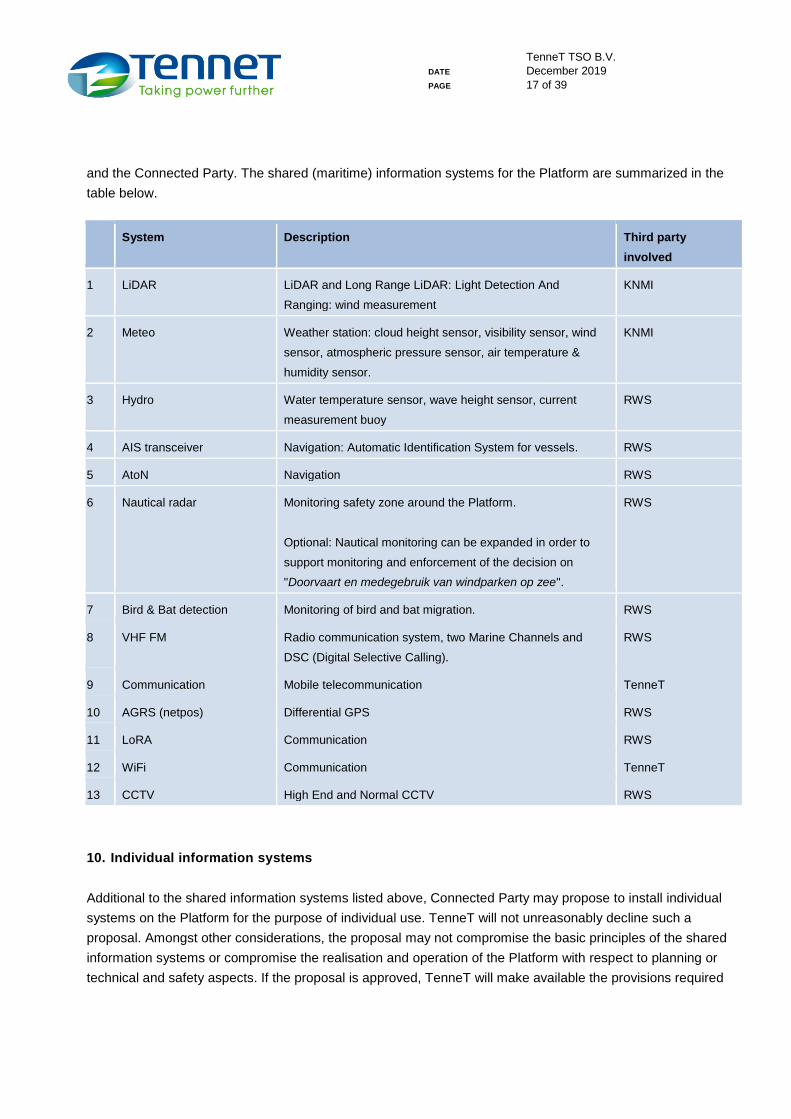
9. Shared (maritime) information systems
TenneT aims to share (maritime) information systems on the Platform with the Connected Party and third
parties where possible, in order to save on space, weight and power consumption. Rijkswaterstaat CIV
("RWS") will organise and maintain these shared systems. TenneT has a role as assessor of technical
feasibility of the systems on the Platform. Any costs related to these systems will be settled between RWS
TenneT TSO B.V.
DATE December 2019
PAGE 17 of 39
and the Connected Party. The shared (maritime) information systems for the Platform are summarized in the
table below.
System Description Third party
involved
1 LiDAR LiDAR and Long Range LiDAR: Light Detection And
Ranging: wind measurement
KNMI
2 Meteo Weather station: cloud height sensor, visibility sensor, wind
sensor, atmospheric pressure sensor, air temperature &
humidity sensor.
KNMI
3 Hydro Water temperature sensor, wave height sensor, current
measurement buoy
RWS
4 AIS transceiver Navigation: Automatic Identification System for vessels. RWS
5 AtoN Navigation RWS
6 Nautical radar Monitoring safety zone around the Platform.
Optional: Nautical monitoring can be expanded in order to
support monitoring and enforcement of the decision on
"Doorvaart en medegebruik van windparken op zee".
RWS
7 Bird & Bat detection Monitoring of bird and bat migration. RWS
8 VHF FM Radio communication system, two Marine Channels and
DSC (Digital Selective Calling).
RWS
9 Communication Mobile telecommunication TenneT
10 AGRS (netpos) Differential GPS RWS
11 LoRA Communication RWS
12 WiFi Communication TenneT
13 CCTV High End and Normal CCTV RWS
10. Individual information systems
Additional to the shared information systems listed above, Connected Party may propose to install individual
systems on the Platform for the purpose of individual use. TenneT will not unreasonably decline such a
proposal. Amongst other considerations, the proposal may not compromise the basic principles of the shared
information systems or compromise the realisation and operation of the Platform with respect to planning or
technical and safety aspects. If the proposal is approved, TenneT will make available the provisions required
TenneT TSO B.V.
DATE December 2019
PAGE 18 of 39
for installation.
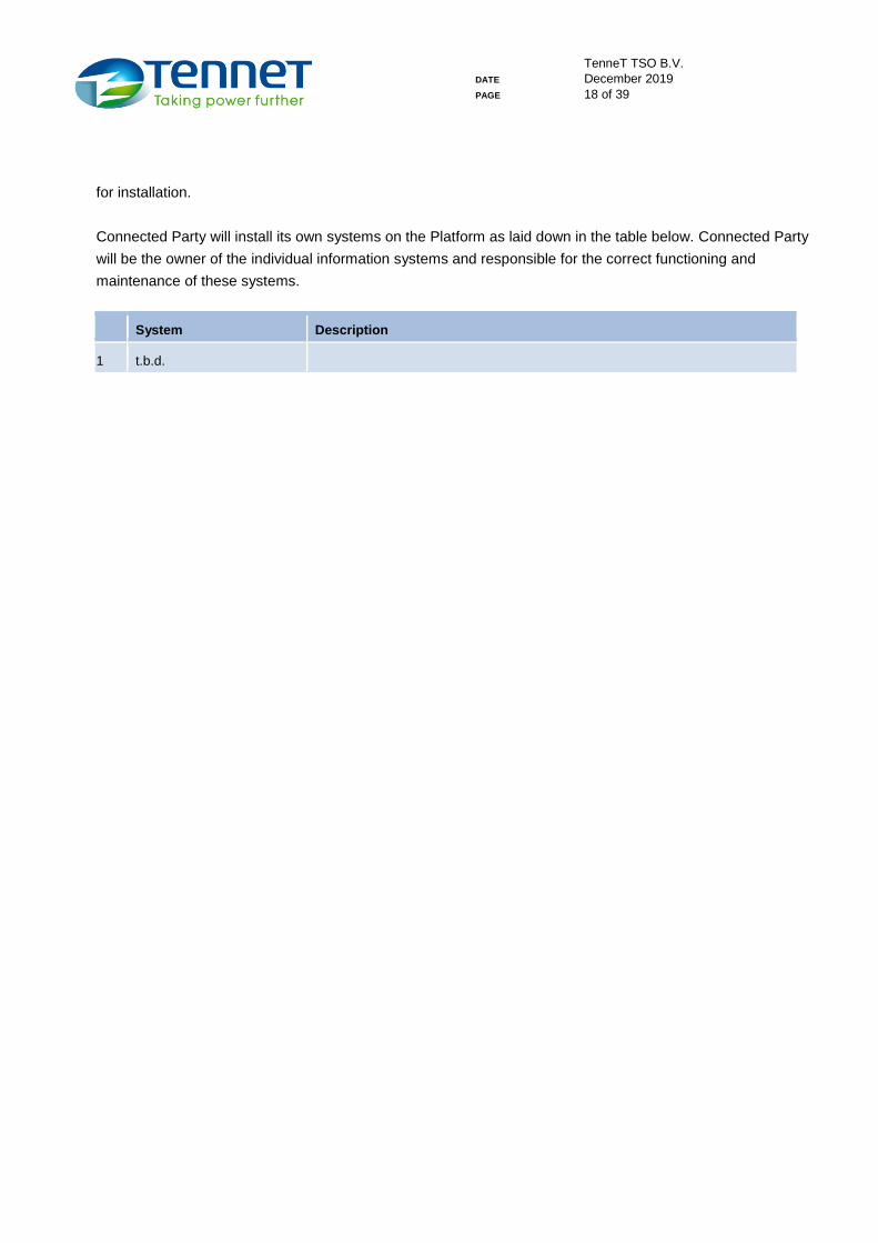
Connected Party will install its own systems on the Platform as laid down in the table below. Connected Party
will be the owner of the individual information systems and responsible for the correct functioning and
maintenance of these systems.
System Description
1 t.b.d.
TenneT TSO B.V.
DATE December 2019
PAGE 19 of 39
Annex 4 Technical requirements applicable for the connection of offshore power
park modules
1. Introduction
This Annex is based on the Commission Regulation (EU) 2016/631 of 14 April 2016 establishing a network
code on requirements for grid connection of generators ('RfG'). RfG, the Act, and relevant clauses of the
current Electricity Grid Code (Netcode Elektriciteit) and the Electricity System Code (Systeemcode
Elektriciteit) apply accordingly, unless indicated otherwise in this Annex.
2. Applicability
With respect to RfG, the Connected Party is considered an Offshore PPM, which results in the applicability of:
- Chapter 4 of title II: "Requirements for offshore power park modules",
- Chapter 4 of title IV: "Compliance testing for offshore power park modules", and
- Chapter 7 of title IV: "Compliance simulations for offshore power park modules".
RfG specifies the general required capabilities of Offshore PPM. Proceedings regarding compliance testing
and compliance simulations related to the RfG requirements will be part of the Connection and Transmission
Agreement (Annex 5: Compliance Activities; applicable testing requirements).
3. Explanatory Notes to RfG
Article 2: Definitions
Definition 1. The Offshore Network is connected to the synchronous area of Continental Europe.
Article 2: Definitions
Definition 2. The nominal voltage of the Connection Point is 66 kV.
TenneT TSO B.V.
DATE December 2019
PAGE 20 of 39
4. Explanatory Notes to the Netcode elektriciteit
Article 3.33 sub 5: Voltage stability – fast fault current injection
The typical response times are depicted in Figura a, for illustrative purposes.
Figure a: Typical transient response of a feedback control system to a step change in input
Article3.34 sub 6: System restoration
Black start capability is not required from Offshore PPMs connected to the Offshore Network (net op zee).
5. Harmonic emission limits
Reference is made to Netcode, article3.34 sub 7.
The Connected Party is responsible for the fulfilment of the requirements with respect to the total harmonic
distortion and the emission limits. TenneT shall specify the maximum allowed harmonic distortion at the 66 kV
Primary Connection Point.
The Connected Party is responsible for taking necessary measures in order to fulfil the requirements with
respect to the harmonic distortion, at its own cost.
TenneT shall define the planning levels of the harmonic emission limits at 66 kV level, which shall be further
allocated to the individual Offshore PPMs based on the capacity according to the Wind Farm Permit and the
equivalent permit of the other Offshore PPM. All Offshore PPMs shall plan for and take measures to fulfil the
requirements, and be accountable for the fulfilment of its requirements at its own costs.
TenneT TSO B.V.
DATE December 2019
PAGE 21 of 39
1. The Connected Party and other Offshore PPM shall not exceed the harmonic emission limits as specified
by TenneT
Since, without detailed information of the Offshore Transmission System, it is not possible yet to define
concrete and complete requirements with respect to the harmonic emission limits, the following approach on
the definition of these requirements will be followed:
a. TenneT specifies the maximum contribution of the individual harmonic voltages to the THD at the
Connection Point (conformity will be assessed per transformer secondary winding on each 66 kV busbar
section). TenneT will provide the frequency sweeps of the harmonic grid impedance at the 380 kV
onshore connection to the national grid together with all impedances of the (offshore) grid between 380 kV
onshore connection and the 66 kV offshore connection point of the Connected Party. These frequency
sweeps can be used for the harmonic study. For initial calculations by Connected Party, TenneT has
provided two memoranda:
“Harmonic impedance loci at EHV-grid connection point for the offshore areas HKN and HKW-
alpha” dated 29 November 2019,
“Harmonic impedance loci at 66 kV connection point, location Hollandse Kust Noord and
Hollandse Kust West-alpha” dated 14 December 2019.
b. The Connected Party shall deliver their wind farm grid specifications and the contribution of the individual
harmonic voltages at the Connection Point (conformity will be assessed per transformer secondary
winding on each 66 kV busbar section) as a percentage of the rated voltage at the busbar section (66 kV)
(95% and 99,9% percentile values). The Connected Party shall prove through calculation that its
Installation complies with the requirements, summation is allowed per part. The Connected Party shall
consult TenneT if compliance cannot be achieved without the installation of filter equipment. As part of
this consultation the Connected Party shall specify the root loci for which compliance can be achieved
without filters. In case a special situation requires additional investigation to assess the compliance,
TenneT and Connected Party will align the exchange of additionally required information for this purpose.
c. An independent third party, to be assigned by TenneT, will perform an overall harmonic study to verify that
the planning levels at the Platform are not exceeded. This study will investigate the harmonic behaviour of
the grid including all connected Offshore PPMs to the Platform (including the Connected Party). All parties
shall make the necessary information for these studies available and share it with the independent third
party without restrictions, although based on a non-disclosure agreement. The study is part of the
conformity test procedure.
d. After realisation of the Connection, as part of the compliance activities, the harmonic voltage levels at the
Connection Point (per transformer secondary winding on each 66 kV busbar section) will be measured.
Compliance shall be assessed by comparison of measured voltages against the planning levels.
Additionally, not part of compliancy assessment though, the measured voltages will be compared to the
agreed design values calculated by the Connected Party. This comparison will be discussed between
TenneT TSO B.V.
DATE December 2019
PAGE 22 of 39
TenneT and Connected Party in order to understand any deviations between measured voltages and
agreed design values and gain a further understanding of the potential impact of such deviations.
2. Regarding the responsibility for maintaining power quality
TenneT is responsible for undoing, at the onshore connection of the Platform to the onshore transmission
system, the impact of the total Offshore Transmission System (export cabling and 66 kV cables) to the
onshore transmission system for electricity with respect to the harmonic amplification;
The design criteria for the Connected Party and the other Offshore PPM shall be based on the compliancy
and planning levels of the THD at the 66 kV busbar.
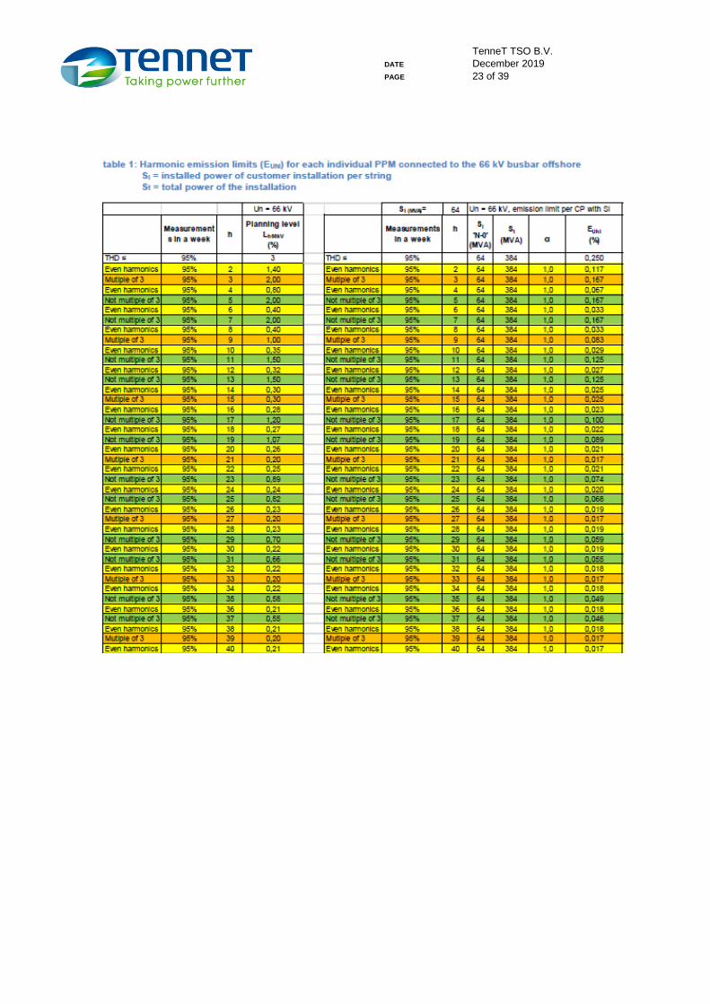
3. Harmonic emission limits
The harmonic emission level EUhi is defined per harmonic order and per installation directly supplying the 66
kV busbar. The following remarks are made:
1) the size of each installation (string) is a PPM design parameter and preliminary based at 64 MVA
(exact parameter is depending upon grid design of the Connected Party);
2) under normal operating conditions, each PPM is individually connected to a single export cable to the
onshore grid connection. The system is designed to facilitate all PPMs connected to one Platform
even during an outage, although under limited conditions. The harmonic emission limits are defined
for the latter case.
The harmonic emission limits presented in table 1 are based on a PPM layout with six strings of connected
turbines, each string has 64 MVA of installed power. In case the design of the PPM deviates from this starting
point (but still same installed power 'Si' per string), the values of EUhi shall be adjusted according to the
formula:
EUhi, new = EUhi, table 1 * 6 * (Si, new / St, new).
The harmonic emission limits in table 1 are also based on only connecting the six strings of 64 MVA installed
power without connecting also another consumer to the Platform. In case of another consumer connected to
the Platform, the values of EUhi shall be adjusted according to the formula:
EUhi, new = EUhi, table 1 * SOWP / (SOWP + Sconsumer).
TenneT TSO B.V.
DATE December 2019
PAGE 23 of 39
TenneT TSO B.V.
DATE December 2019
PAGE 24 of 39
Annex 5 Compliance Activities; applicable testing requirements
1. Scope
The document “RfG compliance verification”, available on the site of “Netbeheer Nederland”
(https://www.netbeheernederland.nl/dossiers/regulering-20/documenten), applies to Connected Party.
2. Introduction
The commissioning will be divided into two main consecutive activities: (1) Site Acceptance Test, Hot
Commissioning (SAT) activities, and (2) compliance testing activities.
1. Site Acceptance Test, Hot-Commissioning (SAT) activities:
Responsibility of the Connected Party and the Connected Party shall mitigate any risk that the
energisation of its Installation jeopardises the Transmission System.
SAT program of the Connected Party shall be approved by, and scheduled in cooperation with
TenneT.
2. Compliance testing activities:
As described in RfG, chapter 4 of Title IV "Compliance testing for offshore power park modules"
apply, and
Are further detailed in the document “RfG compliance verification”, with the additions as noted below.
3. Notifications
The operational notification procedure, RfG, Title III, chapter 1, is applicable. The procedure is further detailed
below:
3.1 Energisation Operational Notification (EON);
3.2 First Interim Operational Notification (ION1);
3.3 Second Interim Operational Notification (ION2);
3.4 Final Operational Notification (FON).
3.1 Energisation Operational Notification (EON)
An Energisation Operational Notification (EON) issued by TenneT is needed before energizing the
Connection, the wind farm grid and the wind farm auxiliaries (Offshore PPM).
Procedure:
- The Connected Party shall submit an itemised statement of compliance to TenneT for issuing an
TenneT TSO B.V.
DATE December 2019
PAGE 25 of 39
EON.
- This statement of compliance shall contain the following documents and reports:
1. A signed CTA;
2. A protection and control settings document, approved by TenneT;
3. A signal exchange list;
4. An overall testing and commissioning plan, including, but not limited to:
Planning of personnel support at the platform
Planning of personnel support at the National Control Centre of TenneT
Contact details of the authorised responsible commissioning manager
Planning of reactive power generation or consumption per energised string
Confirmation that Power Quality measurements can and will be performed during
the commissioning;
5. A report proving the harmonic compliancy, approved by TenneT;
6. A report proving compliance with insulation coordination requirements, approved by
TenneT.
Planning:
- The Connected Party shall have an EON at least one (1) month before the energisation of the first
string.
- Within maximum four (4) weeks after receiving the statement of compliance of the Connected Party,
TenneT will respond. If the assessment of the application is positive, an EON will be granted by
return.
- A period of minimum ten (10) months shall be scheduled for review, discussion and approval by
TenneT of the report regarding the harmonic compliancy.
3.2 First Interim Operational Notification (ION1)
A first Interim Operational Notification (ION1) issued by TenneT is needed before taking the first WTG in
operation for power generation.
Procedure:
- The Connected Party shall submit an itemised statement of compliance to TenneT for issuing an
ION1.
- This application shall contain the following documents and reports:
1. An EON or an application for an EON;
2. Technical data of the turbines (according to IEC 61400-21, annex A);
3. Technical data of the wind farm including, but not limited to, array cable specifications,
turbine transformer specifications;
4. Report of studies demonstrating the expected steady-state and dynamic performance;
5. Simulation models, as specified by point (c) of Article 15(6) of the RfG.
TenneT TSO B.V.
DATE December 2019
PAGE 26 of 39
Planning:
- Connected Party shall have an ION1 at least one (1) month before the taking the first WTG in
operation.
- Within maximum four (4) weeks after receiving the statement of compliance of the Connected Party,
TenneT will respond. If the assessment of the statement of compliance is positive and an EON is
already granted, an ION1 will be granted by return.
3.3 Second Interim Operational Notification (ION2)
A second Interim Operational Notification (ION2) issued by TenneT is needed after reaching 60 MW installed
and commissioned WTG capacity.
Procedure:
- The Connected Party shall submit an itemised statement of compliance to TenneT for issuing an
ION2.
- This statement of compliance shall contain the following documents and reports:
1. An ION1;
2. Interim Power Quality measurements;
3. Interim voltage control test.
Planning:
- The Connected Party shall have an ION2 no later than two (2) months after reaching 60 MW installed
and commissioned WTG capacity.
- Within maximum four (4) weeks after receiving the application of the Connected Party, TenneT will
respond. If the assessment of the statement of compliance is positive, an ION2 will be granted by
return.
3.4 Final Operational Notification (FON)
A Final Operational Notification (FON) issued by TenneT is needed after reaching full capacity installed and
commissioned.
Procedure:
- The Connected Party shall submit an itemised statement of compliance to TenneT for issuing a FON.
- This statement of compliance shall contain the following documents and reports:
1. An ION2;
2. Update of applicable technical data, simulation models and studies including the use of
actual measured values during testing.
3. Final report on Power Quality measurements;
4. Final report on on-site tests.
Planning:
- The Connected Party shall have a FON no later than four (4) months after reaching full installed and

TenneT TSO B.V.
DATE December 2019
PAGE 27 of 39
commissioned WTG capacity.
- Within maximum four (4) weeks after receiving the statement of compliance of the Connected Party,
TenneT will respond. If the assessment of the application is positive, a FON will be granted by return.
4. Additional provisions
In order to remain system stability TenneT is entitled to:
refuse to energise the Connection in case an EON cannot be granted;
order to stop power generation by the Offshore PPM (refuse feed-in) in case an ION2 cannot be
granted ultimately four (4) months after reaching installed and commissioned WTG capacity of 60
MW;
order to stop power generation by the Offshore PPM (refuse feed-in) in case a FON cannot be
granted ultimately four (4) months after reaching full installed and commissioned WTG capacity.
TenneT will not issue a refusal as mentioned here on unreasonable grounds.
5. Further detailed commissioning planning
Because the Offshore PPM Installation will consist of several physical cable connections, which might be
commissioned separately, a further detailed commissioning planning shall be agreed upon by the Parties.
The SAT and commissioning could then be done per 66 kV cable with connected WTGs, where the
requirements will be assessed proportionally in respect with the technical capabilities per connected 66 kV
cable.
It is acknowledged by the Parties that necessary information for compliance testing activities shall be made
available and shared without restrictions.
6. Applicable testing requirements
The document “RfG compliance verification”, should be read as follows:
Section 4.2.20 Power Quality
PLTi ≤ 0,25
PSTi ≤ 0,35
Section 4.2.21 Isolation coordination
Transient voltages may never exceed the BIL of 325 kV.
TenneT TSO B.V.
DATE December 2019
PAGE 28 of 39
Annex 6 Operational arrangements and exchange of information
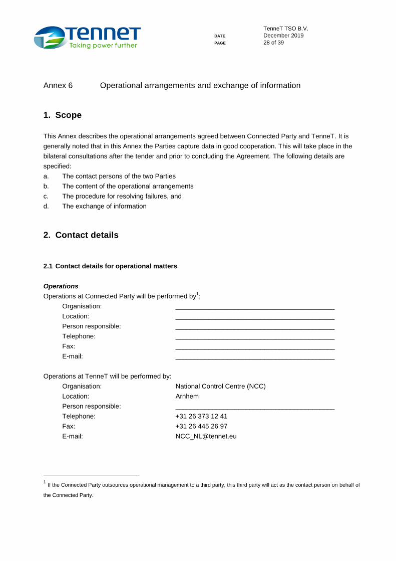
1. Scope
This Annex describes the operational arrangements agreed between Connected Party and TenneT. It is
generally noted that in this Annex the Parties capture data in good cooperation. This will take place in the
bilateral consultations after the tender and prior to concluding the Agreement. The following details are
specified:
a. The contact persons of the two Parties
b. The content of the operational arrangements
c. The procedure for resolving failures, and
d. The exchange of information
2. Contact details
2.1 Contact details for operational matters
Operations
Operations at Connected Party will be performed by1:
Organisation: ___________________________________________
Location: ___________________________________________
Person responsible: ___________________________________________
Telephone: ___________________________________________
Fax: ___________________________________________
E-mail: ___________________________________________
Operations at TenneT will be performed by:
Organisation: National Control Centre (NCC)
Location: Arnhem
Person responsible: ___________________________________________
Telephone: +31 26 373 12 41
Fax: +31 26 445 26 97
E-mail: [email protected]
1 If the Connected Party outsources operational management to a third party, this third party will act as the contact person on behalf of
the Connected Party.
TenneT TSO B.V.
DATE December 2019
PAGE 29 of 39
2.2 Contact details for planning the availability of the TenneT transmission system
Planned Unavailability
On working days, Connected Party’s contact person for matters concerning Planned Unavailability within the
meaning of Article 4.2.2.2 of the Grid Code will be:
Organisation: ___________________________________________
Location: ___________________________________________
Person responsible: ___________________________________________
Telephone: ___________________________________________
Fax: ___________________________________________
E-mail: ___________________________________________
On working days, TenneT’s operational support department can be reached in the following ways:
Organisation: TenneT’s operational support department (planned unavailability group)
Telephone: +31 26 373 17 61
Fax: +31 26 373 24 53
E-mail: [email protected]
2.3 Changes to contact details
The Connected Party shall ensure that changes to contact details are notified to TenneT by:
Organisation: ___________________________________________
Location: ___________________________________________
Person responsible: ___________________________________________
Telephone: ___________________________________________
Fax: ___________________________________________
E-mail: ___________________________________________
Correspondence address: ___________________________________________
The TenneT Customer Relationship Manager will be responsible for changing the contact details:
Organisation: Customers & Markets
Location: Arnhem
Person responsible: ___________________________________________
Telephone: ___________________________________________
E-mail: ___________________________________________
Correspondence address: TenneT TSO B.V. Customers & Markets
Postbus 718
NL-6800 AS Arnhem
TenneT TSO B.V.
DATE December 2019
PAGE 30 of 39
3. Content of arrangements
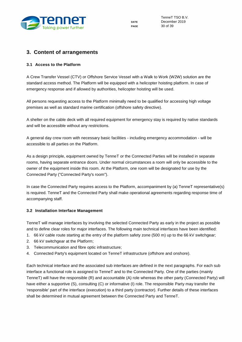
3.1 Access to the Platform
A Crew Transfer Vessel (CTV) or Offshore Service Vessel with a Walk to Work (W2W) solution are the
standard access method. The Platform will be equipped with a helicopter hoisting platform. In case of
emergency response and if allowed by authorities, helicopter hoisting will be used.
All persons requesting access to the Platform minimally need to be qualified for accessing high voltage
premises as well as standard marine certification (offshore safety directive).
A shelter on the cable deck with all required equipment for emergency stay is required by native standards
and will be accessible without any restrictions.
A general day crew room with necessary basic facilities - including emergency accommodation - will be
accessible to all parties on the Platform.
As a design principle, equipment owned by TenneT or the Connected Parties will be installed in separate
rooms, having separate entrance doors. Under normal circumstances a room will only be accessible to the
owner of the equipment inside this room. At the Platform, one room will be designated for use by the
Connected Party ("Connected Party's room").
In case the Connected Party requires access to the Platform, accompaniment by (a) TenneT representative(s)
is required. TenneT and the Connected Party shall make operational agreements regarding response time of
accompanying staff.
3.2 Installation Interface Management
TenneT will manage interfaces by involving the selected Connected Party as early in the project as possible
and to define clear roles for major interfaces. The following main technical interfaces have been identified:
1. 66 kV cable route starting at the entry of the platform safety zone (500 m) up to the 66 kV switchgear;
2. 66 kV switchgear at the Platform;
3. Telecommunication and fibre optic infrastructure;
4. Connected Party's equipment located on TenneT infrastructure (offshore and onshore).
Each technical interface and the associated sub interfaces are defined in the next paragraphs. For each sub
interface a functional role is assigned to TenneT and to the Connected Party. One of the parties (mainly
TenneT) will have the responsible (R) and accountable (A) role whereas the other party (Connected Party) will
have either a supportive (S), consulting (C) or informative (I) role. The responsible Party may transfer the
'responsible' part of the interface (execution) to a third party (contractor). Further details of these interfaces
shall be determined in mutual agreement between the Connected Party and TenneT.
TenneT TSO B.V.
DATE December 2019
PAGE 31 of 39
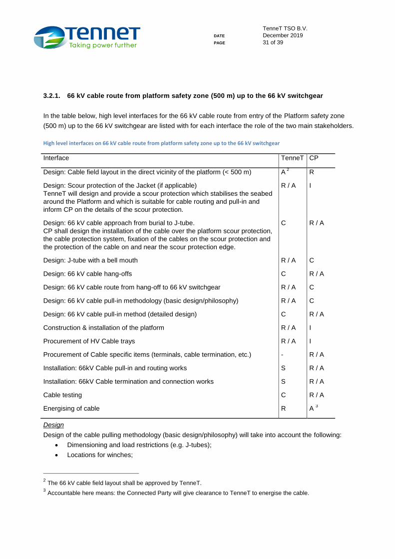
3.2.1. 66 kV cable route from platform safety zone (500 m) up to the 66 kV switchgear
In the table below, high level interfaces for the 66 kV cable route from entry of the Platform safety zone
(500 m) up to the 66 kV switchgear are listed with for each interface the role of the two main stakeholders.
High level interfaces on 66 kV cable route from platform safety zone up to the 66 kV switchgear
Interface TenneT CP
Design: Cable field layout in the direct vicinity of the platform (< 500 m) A 2 R
Design: Scour protection of the Jacket (if applicable)
TenneT will design and provide a scour protection which stabilises the seabed
around the Platform and which is suitable for cable routing and pull-in and
inform CP on the details of the scour protection.
R / A I
Design: 66 kV cable approach from burial to J-tube.
CP shall design the installation of the cable over the platform scour protection,
the cable protection system, fixation of the cables on the scour protection and
the protection of the cable on and near the scour protection edge.
C R / A
Design: J-tube with a bell mouth R / A C
Design: 66 kV cable hang-offs C R / A
Design: 66 kV cable route from hang-off to 66 kV switchgear R / A C
Design: 66 kV cable pull-in methodology (basic design/philosophy) R / A C
Design: 66 kV cable pull-in method (detailed design) C R / A
Construction & installation of the platform R / A I
Procurement of HV Cable trays R / A I
Procurement of Cable specific items (terminals, cable termination, etc.) - R / A
Installation: 66kV Cable pull-in and routing works S R / A
Installation: 66kV Cable termination and connection works S R / A
Cable testing C R / A
Energising of cable R A 3
Design
Design of the cable pulling methodology (basic design/philosophy) will take into account the following:
Dimensioning and load restrictions (e.g. J-tubes);
Locations for winches;
2 The 66 kV cable field layout shall be approved by TenneT.
3 Accountable here means: the Connected Party will give clearance to TenneT to energise the cable.

TenneT TSO B.V.
DATE December 2019
PAGE 32 of 39
Temporary storage area + facilities (scaffolding) on the cable deck in case the cables are stored
before the topside is installed on top;
Working area on the cable deck for cable works;
Pull-in and routing of cables up to the 66 kV switchgear without joints or junction boxes on the cable
deck.
Based on the generic cable pulling methodology4, the Connected Party shall consult TenneT on detailed
design for the cable pulling and installation method of 66 kV cables. With respect to the J-tubes, they have a
fixed position on the jacket which is determined in the basic design. The angle of the J-tube may however be
(slightly) adapted as long as there are no conflicts with neighbouring cables or J-tubes. TenneT has to be
consulted in this design process and has to approve the method. TenneT will organise regular design
meetings with the Connected Parties to the Platform.
Procurement for items of the 66kV Cable route
TenneT will, after a detailed design has been submitted by the Connected Party, procure the cable trays for
the main cable route. All components that are cable specific (such as cable supports to and from the main
cable route and the cable terminations) will be procured by the Connected Party.
Installation of 66 kV Cables
The Connected Party is responsible for installation of cable protection (if applicable), the actual cable pull-in,
cable storage (if any), J-Tube pigging, cable fastening and termination works making use of equipment such
as pulling winch, hang-offs, pull-in wire or messenger wire, etc.
TenneT will facilitate these activities of the Connected Party with regards to the Platform structure itself. The
Connected Party will get the possibility to install pull-in equipment on the Platform while it is under
construction onshore.
Before installation and after installation of the 66 kV cables on the Platform by the Connected Party and at
such other moments as the Parties may agree on, joint inspections will be held to assess and log possible
damages caused by one Party to property of the other Party.
Testing and commissioning of 66 kV cables
After installation, the Connected Party shall be responsible for testing of the 66 kV cables, including HV tests,
phase checks, sheath testing and optical time-domain reflectometer (OTDR) tests on optical fibres.
4 Generic cable pulling methodology as described in the document "Standard 700 MW AC Offshore Substation Cable
Pulling Methodology " of December 2019, outlining the general methodology regarding the pulling of HV sea cables on the
standard 700MW AC offshore substation. This methodology will be the basis for the detailed cable pulling methods which
will be established by the various cable contractors in close cooperation with the platform contractor during the detailed
design phase of the project.
TenneT TSO B.V.
DATE December 2019
PAGE 33 of 39
For commissioning of the 66 kV cables, TenneT will be responsible for energising of the 66 kV cables and
TenneT will execute actual switching operation after clearance is given by the Connected Party.
For the testing and commissioning phase agreements shall be made between TenneT and the Connected
Party including agreements on installation responsibility (nominated person5) and LOTO (Lock-out, Tag-out)
principles.
Depending on the testing equipment needed, the equipment may be placed in vicinity of the Gas Insulated
Switchgear (GIS) equipment or on the top deck of the Platform. The Connected Party may need HV cables,
cable terminations and/or test bushings to connect the test equipment to the 66 kV cable bay.
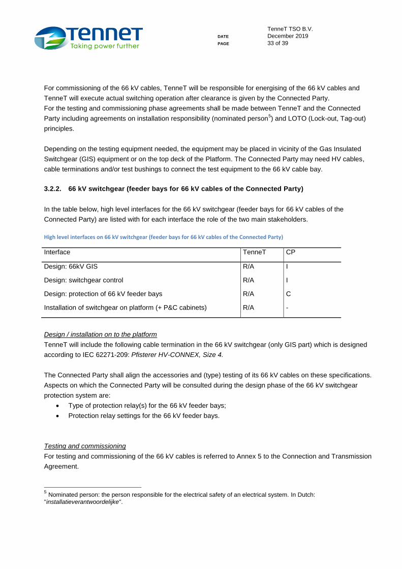
3.2.2. 66 kV switchgear (feeder bays for 66 kV cables of the Connected Party)
In the table below, high level interfaces for the 66 kV switchgear (feeder bays for 66 kV cables of the
Connected Party) are listed with for each interface the role of the two main stakeholders.
High level interfaces on 66 kV switchgear (feeder bays for 66 kV cables of the Connected Party)
Interface TenneT CP
Design: 66kV GIS R/A I
Design: switchgear control R/A I
Design: protection of 66 kV feeder bays R/A C
Installation of switchgear on platform (+ P&C cabinets) R/A -
Design / installation on to the platform
TenneT will include the following cable termination in the 66 kV switchgear (only GIS part) which is designed
according to IEC 62271-209: Pfisterer HV-CONNEX, Size 4.
The Connected Party shall align the accessories and (type) testing of its 66 kV cables on these specifications.
Aspects on which the Connected Party will be consulted during the design phase of the 66 kV switchgear
protection system are:
Type of protection relay(s) for the 66 kV feeder bays;
Protection relay settings for the 66 kV feeder bays.
Testing and commissioning
For testing and commissioning of the 66 kV cables is referred to Annex 5 to the Connection and Transmission
Agreement.
5 Nominated person: the person responsible for the electrical safety of an electrical system. In Dutch:
"installatieverantwoordelijke".
TenneT TSO B.V.
DATE December 2019
PAGE 34 of 39
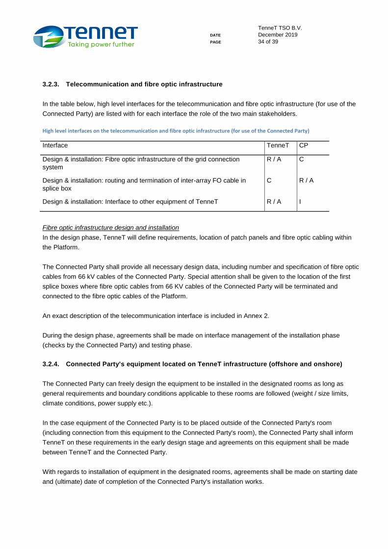
3.2.3. Telecommunication and fibre optic infrastructure
In the table below, high level interfaces for the telecommunication and fibre optic infrastructure (for use of the
Connected Party) are listed with for each interface the role of the two main stakeholders.
High level interfaces on the telecommunication and fibre optic infrastructure (for use of the Connected Party)
Interface TenneT CP
Design & installation: Fibre optic infrastructure of the grid connection
system
R / A C
Design & installation: routing and termination of inter-array FO cable in
splice box
C R / A
Design & installation: Interface to other equipment of TenneT R / A I
Fibre optic infrastructure design and installation
In the design phase, TenneT will define requirements, location of patch panels and fibre optic cabling within
the Platform.
The Connected Party shall provide all necessary design data, including number and specification of fibre optic
cables from 66 kV cables of the Connected Party. Special attention shall be given to the location of the first
splice boxes where fibre optic cables from 66 KV cables of the Connected Party will be terminated and
connected to the fibre optic cables of the Platform.
An exact description of the telecommunication interface is included in Annex 2.
During the design phase, agreements shall be made on interface management of the installation phase
(checks by the Connected Party) and testing phase.
3.2.4. Connected Party's equipment located on TenneT infrastructure (offshore and onshore)
The Connected Party can freely design the equipment to be installed in the designated rooms as long as
general requirements and boundary conditions applicable to these rooms are followed (weight / size limits,
climate conditions, power supply etc.).
In the case equipment of the Connected Party is to be placed outside of the Connected Party's room
(including connection from this equipment to the Connected Party's room), the Connected Party shall inform
TenneT on these requirements in the early design stage and agreements on this equipment shall be made
between TenneT and the Connected Party.
With regards to installation of equipment in the designated rooms, agreements shall be made on starting date
and (ultimate) date of completion of the Connected Party's installation works.
TenneT TSO B.V.
DATE December 2019
PAGE 35 of 39
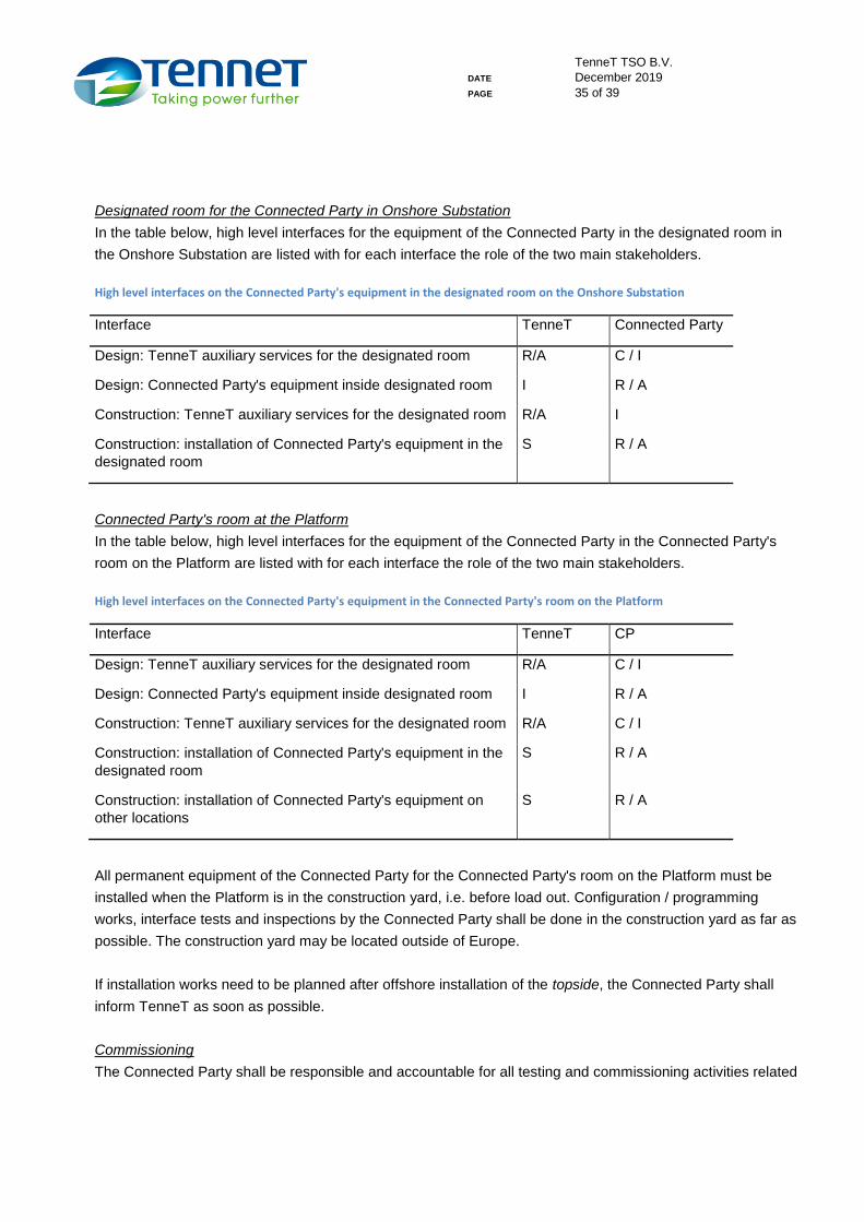
Designated room for the Connected Party in Onshore Substation
In the table below, high level interfaces for the equipment of the Connected Party in the designated room in
the Onshore Substation are listed with for each interface the role of the two main stakeholders.
High level interfaces on the Connected Party's equipment in the designated room on the Onshore Substation
Interface TenneT Connected Party
Design: TenneT auxiliary services for the designated room R/A C / I
Design: Connected Party's equipment inside designated room I R / A
Construction: TenneT auxiliary services for the designated room R/A I
Construction: installation of Connected Party's equipment in the
designated room
S R / A
Connected Party's room at the Platform
In the table below, high level interfaces for the equipment of the Connected Party in the Connected Party's
room on the Platform are listed with for each interface the role of the two main stakeholders.
High level interfaces on the Connected Party's equipment in the Connected Party's room on the Platform
Interface TenneT CP
Design: TenneT auxiliary services for the designated room R/A C / I
Design: Connected Party's equipment inside designated room I R / A
Construction: TenneT auxiliary services for the designated room R/A C / I
Construction: installation of Connected Party's equipment in the
designated room
S R / A
Construction: installation of Connected Party's equipment on
other locations
S R / A
All permanent equipment of the Connected Party for the Connected Party's room on the Platform must be
installed when the Platform is in the construction yard, i.e. before load out. Configuration / programming
works, interface tests and inspections by the Connected Party shall be done in the construction yard as far as
possible. The construction yard may be located outside of Europe.
If installation works need to be planned after offshore installation of the topside, the Connected Party shall
inform TenneT as soon as possible.
Commissioning
The Connected Party shall be responsible and accountable for all testing and commissioning activities related
TenneT TSO B.V.
DATE December 2019
PAGE 36 of 39
to the Connected Party's equipment on TenneT's infrastructure.
TenneT will support the Connected Party during testing and commissioning with regards to the services
provided by TenneT (66 kV GIS switching actions, auxiliary services to designated rooms, shared data
acquisition systems, optical fibres).
3.2.5. Coordination during offshore works
TenneT will be responsible (R) and accountable (A) for the Platform and therefore for planning, coordination
and safety rules, where the Connected Party will be supportive (S). To manage planning, coordination and
safety properly, TenneT will be responsible for providing work permits for offshore works within the safety
zone (500 m) of the Platform and for all works on the Platform.
The Connected Party will support TenneT with this coordination by correct and on-time application for work
permits and by participating in all planning, interface and progress meetings to be scheduled for this purpose.
TenneT will define the method for (emergency) communication within the project site (platform safety zone
and the Platform itself).
Further agreements between TenneT and the Connected Party on marine coordination and coordination of
works on the Platform shall be made in a later phase.
3.2.6. Document management
Exchange of documents and formal communication between the Parties shall be through the document
management system "Think Project!".
3.3 Operations & Maintenance (O&M) interface
The major O&M interface categories are described below. Further details of these interfaces will be worked
out in cooperation with the parties connected to the Platform (during the construction phase).
Identified operational interfaces
Logistics/transport to the Platform
Logistics/transport from the Platform
Work permitting process
Installation responsibility / Work responsibility / designated persons
Access to the Platform for the SCADA controls system
Communications regarding activities around the Platform
Switching activities by TenneT on behalf of the Connected Party
TenneT TSO B.V.
DATE December 2019
PAGE 37 of 39
Operations of grid connection including fibre optic communication infrastructure
Power interruptions due to failures on the Platform or in the 66kV Connection
Identified maintenance interfaces:
Maintenance of the 220 kV equipment
Maintenance 66 kV inter-array cables Connected Party and 66 kV equipment TenneT (including
protection control)
Maintenance equipment Connected Party on the Platform
Maintenance combined equipment on the Platform
Metering activities (calibrations)
3.4 Switching procedures
Supplemental to relevant (international) standards and guidelines, a specific switching procedure may be in
place that the Parties must follow to assure safety, continuity, etc. If this situation occurs, it is detailed in the
table below.
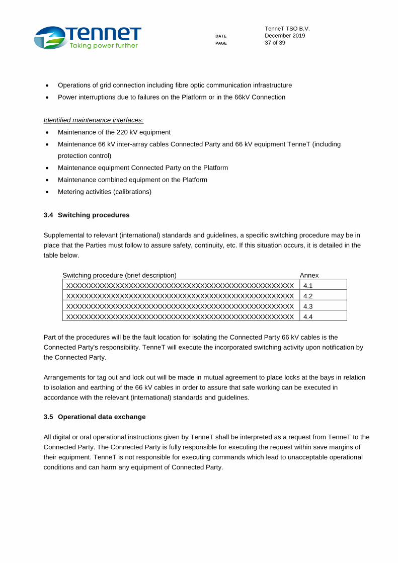
Switching procedure (brief description) Annex
XXXXXXXXXXXXXXXXXXXXXXXXXXXXXXXXXXXXXXXXXXXXXXXXXXX 4.1
XXXXXXXXXXXXXXXXXXXXXXXXXXXXXXXXXXXXXXXXXXXXXXXXXXX 4.2
XXXXXXXXXXXXXXXXXXXXXXXXXXXXXXXXXXXXXXXXXXXXXXXXXXX 4.3
XXXXXXXXXXXXXXXXXXXXXXXXXXXXXXXXXXXXXXXXXXXXXXXXXXX 4.4
Part of the procedures will be the fault location for isolating the Connected Party 66 kV cables is the
Connected Party's responsibility. TenneT will execute the incorporated switching activity upon notification by
the Connected Party.
Arrangements for tag out and lock out will be made in mutual agreement to place locks at the bays in relation
to isolation and earthing of the 66 kV cables in order to assure that safe working can be executed in
accordance with the relevant (international) standards and guidelines.
3.5 Operational data exchange
All digital or oral operational instructions given by TenneT shall be interpreted as a request from TenneT to the
Connected Party. The Connected Party is fully responsible for executing the request within save margins of
their equipment. TenneT is not responsible for executing commands which lead to unacceptable operational
conditions and can harm any equipment of Connected Party.
TenneT TSO B.V.
DATE December 2019
PAGE 38 of 39
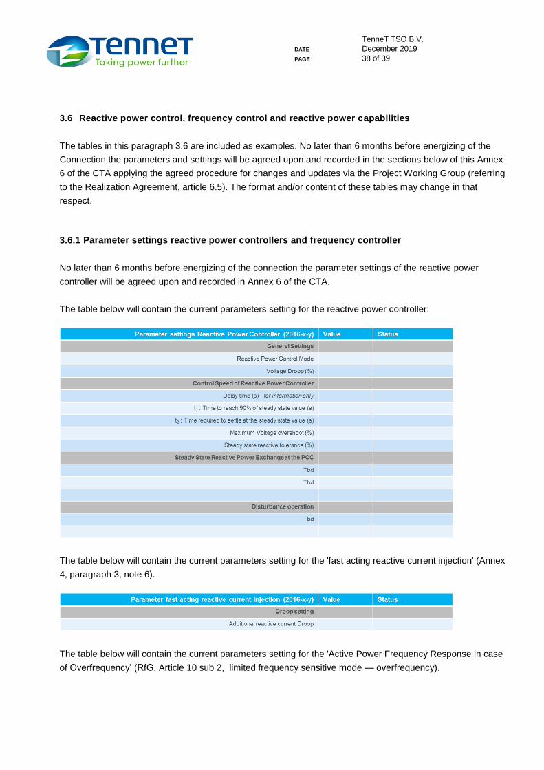
3.6 Reactive power control, frequency control and reactive power capabilities
The tables in this paragraph 3.6 are included as examples. No later than 6 months before energizing of the
Connection the parameters and settings will be agreed upon and recorded in the sections below of this Annex
6 of the CTA applying the agreed procedure for changes and updates via the Project Working Group (referring
to the Realization Agreement, article 6.5). The format and/or content of these tables may change in that
respect.
3.6.1 Parameter settings reactive power controllers and frequency controller
No later than 6 months before energizing of the connection the parameter settings of the reactive power
controller will be agreed upon and recorded in Annex 6 of the CTA.
The table below will contain the current parameters setting for the reactive power controller:
The table below will contain the current parameters setting for the 'fast acting reactive current injection' (Annex
4, paragraph 3, note 6).
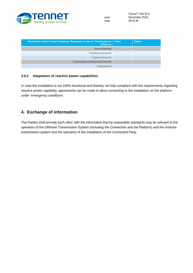
The table below will contain the current parameters setting for the 'Active Power Frequency Response in case
of Overfrequency’ (RfG, Article 10 sub 2, limited frequency sensitive mode — overfrequency).
TenneT TSO B.V.
DATE December 2019
PAGE 39 of 39
3.6.2 Adaptation of reactive power capabilities
In case the installation is not 100% functional and thereby not fully compliant with the requirements regarding
reactive power capability, agreements can be made to allow connecting to the installation on the platform
under 'emergency conditions'.
4. Exchange of information
The Parties shall provide each other with the information that by reasonable standards may be relevant to the
operation of the Offshore Transmission System (including the Connection and the Platform) and the onshore
transmission system and the operation of the Installation of the Connected Party.