Embed Size (px)
Citation preview

Appendix D
H:\WP\1346\Appendices\FEIS\D - Drawdown\CamRdy\App_D.doc
Annex V
Concrete Structures Removal Plan
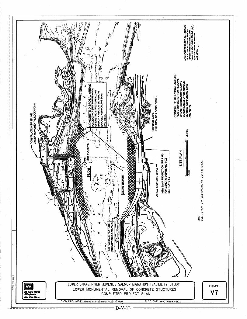
Figure V1 Lower Granite Sequences of Concrete Removal and Cofferdam Figure V2 Little Goose Sequence of Concrete Removal and Cofferdam Figure V3 Lower Monumental Sequence of Construction Phase 1 and 2 Figure V4 Ice Harbor Sequence of Construction Phase 1 and 2 Figure V5 Lower Granite Removal of Concrete Structures Figure V6 Little Goose Removal of Concrete Structures Figure V7 Lower Monumental Removal of Concrete Structures Figure V8 Ice Harbor Removal of Concrete Structures

Appendix D
H:\WP\1346\Appendices\FEIS\D - Drawdown\CamRdy\Annexes\ANNEXV-R.DOC
D-V-1
Annex V: Concrete Structures Removal Plan V.1 General The fundamental method of establishing a natural river is to remove the embankments at each of the four lower Snake River dams and leave the concrete structures in place. This annex presents the additional steps needed to fully remove visible concrete structures. This is a concept-level investigation since it considers only gross quantities of materials in the major structures.
V.2 Description of Existing Structures Each hydropower facility on the lower Snake River contains at least four major concrete structures that would be removed: the powerhouse, navigation lock, spillway, and fish facilities (comprised of fish ladders and juvenile fish facilities). Several smaller structures such as non-overflow sections of dam, offices, visitors center, parking lots, roads, and bridges would also be removed. Non-concrete structures include embankment sections not otherwise removed for the new channel and numerous steel structures on the project.
In addition, all mechanical and electrical equipment would be removed, including major generating equipment, (turbines, generators, governors, and exciters) auxiliary equipment, head gates, bulkheads, spillway gates, trashracks, fish screens, transformers, switchyards, and transmission substations.
Following is a brief description of the major structures:
�� Powerhouse Each site has a six-unit powerhouse with adjacent erection bay. The structure is approximately 200 meters (656 feet) long by 75 meters (246 feet) wide. The upstream wall of the powerhouse is essentially a concrete dam that serves as the intake.
�� Spillway Each site has an eight-bay spillway with radial gates, except for Ice Harbor Dam that has 10 bays. Each bay is 15.2 meters (50 feet) wide, separated by piers that are 3.05 meters (10 feet) wide at Ice Harbor and 4.3 meters (14 feet) wide at the other three sites. Little Goose Dam has a flip bucket, and the other three sites have a stilling basin. The stilling basins would be below average riverbed and, therefore, would be left in place.
�� Navigation Lock Each site has a navigation lock with an inside length of approximately 245 meters (804 feet). Walls are massive concrete approximately 47 meters (154 feet) high with a top width of 12 meters (39 feet) to 15.2 meters (50 feet).
�� Fish Ladder Each project has a fish ladder with three entrances: one each on the south shore and north shore, and one end of the powerhouse. Fish ladders are concrete flumes approximately 360 meters long (1,181 feet) and supported on concrete columns. Each ladder has a pump system to supply extra attraction water.

Appendix D
H:\WP\1346\Appendices\FEIS\D - Drawdown\CamRdy\Annexes\ANNEXV-R.DOC
D-V-2
�� Juvenile Fish Facilities Each project has a juvenile fish facility consisting of piping, metal flumes, concrete raceways, a laboratory building, and, in some cases, a separator holding and loading facilities.
�� Non-Overflow Dams Each project has non-overflow concrete gravity dams that join the main structures or serve as cut-off walls. These dams are up to 45 meters (148 feet) high and have a back slope of 3 on 4.
�� Miscellaneous Buildings Each project has some miscellaneous facilities, such as visitors center, offices, parking, roads, and bridges.
�� Embankment Dams Dams on the shore opposite the first stage channel would be left in place above high water level.
V.3 Completed Project Description If this option were implemented, all structures would be removed from above the natural riverbed elevation, allowing the river to flow in as nearly an original configuration as possible. A plan of the completed project for each of the four sites is shown in Figures V1 through V4. These figures illustrate the concrete rubble storage area and the effect of channel widening performed during river channelization.
The work of concrete removal would begin after the work for embankment excavation and river channelization had been completed.
V.4 Cofferdams A cofferdam is necessary to isolate the demolition area from the river channel. Demolition must follow the drawdown activities that restore the river to a “natural” condition. Demolition in advance of drawdown would disrupt ongoing operations and impede the actions necessary to implement the drawdown. In the drawdown plan, following embankment removal, a series of channelization levees would be constructed to form the permanent channel around the remaining concrete structures. Those levees are permeable since they are constructed of shotrock, which allows water to freely pass through the levee. This same channelization of the river would be necessary during demolition. However, the levees must be impervious for demolition so that the interior zone can be dewatered before the work can proceed. Since the cofferdams would be temporary structures, they could be constructed of local gravels instead of the pervious shotrock.
These cofferdams, made of local gravel fill, would be similar in design to the cofferdams used for initial construction of the dams. According to contract documents for original construction, a cut-off trench was made through the cofferdam section, down to rock along the centerline, and held open with a bentonite slurry mix. This same process is proposed for construction of these temporary cofferdams. The trench would be constructed after the cofferdam had reached full height.
Instead of simply extending the new cofferdams to the existing concrete structures like the levee, the cofferdams would actually enclose all the concrete structures and rejoin with the shore.

Appendix D
H:\WP\1346\Appendices\FEIS\D - Drawdown\CamRdy\Annexes\ANNEXV-R.DOC
D-V-3
Cofferdams at Lower Granite and Little Goose would involve only one stage as shown in Figures V5 and V6. The new channels at both sites would be sufficiently large to accommodate a cofferdam and still have acceptable velocities for fish migration. Cofferdams at Lower Monumental and Ice Harbor dams would involve two stages as shown in Figures V7 and V8. Two stages are necessary at these two sites because the temporary channels are too narrow to accommodate an earthfill cross section and maintain acceptable velocities for fish migration. The first stage would be a dike system that joins the end of the navigation lock to the shore enclosing the powerhouse and spillway. Behind this cofferdam, removal of the powerhouse and spillway would be accomplished. The second stage would include removal of the first cofferdam and construction of a second cofferdam enclosing the navigation lock to the opposite and nearest shore.
While the cofferdams and slurry trench were being installed, all equipment would be removed from the site and staged in an area for dismantling and disposal.
Dewatering facilities consisting of multiple pumps and collector ditches would be provided for the interior of the cofferdam areas. Water would be treated locally and returned to the river.
Demolition of concrete structures would be accomplished to an elevation 2 meters (6.6 feet) below the average river bottom level. The draft tube passages, approach, and tail channels would be filled-in with concrete rubble. All concrete remaining in the river below grade would be covered with riprap and river bed material to match the average river grade.
Concrete rubble from demolition would be disposed of by placing it in riprap fashion along the bank of the river within the cofferdam area. Horizontal thickness of the concrete rubble would be approximately 30 meters (about 95 feet). Exposed reinforcing bars and embedded metal would be removed.
After equipment and concrete structures have been demolished, hydraulic excavators working from the cofferdam crest at a point furthest from the shoreline would remove cofferdams. The two equipment spreads would first breach the cofferdam, then excavate in opposite directions towards the riverbank, loading haul trucks to remove the cofferdam material for disposal away from the river edge.
V.5 Concrete Removal (Demolition) The study team assumed drill and blast would remove all concrete. The team estimated gross quantities and based removal costs on unit prices for drill and blasting mass concrete and reinforced concrete. The team determined that, while other methods of demolition such as hydraulic crushing might be more appropriate for specific structures, such a detailed approach to demolition was not within the scope of this effort. The plan assumed mass concrete would be removed in approximately 6-meter (20-foot) lifts by drill and blast.
The team determined that demolition of the powerhouse, spillway, fish facilities, and navigation locks (at Lower Granite and Little Goose) could proceed simultaneously. All holes would be drilled for nominal lift heights of about 6 vertical meters, and the site cleared and blasted. Load and haul to the spoil area could proceed while the next lift of holes were being readied for blast.
The following equipment would be used for demolition:
�� Drills—Rotary, air track rigs drilling 5-centimeter (2-inch) holes would be used.

Appendix D
H:\WP\1346\Appendices\FEIS\D - Drawdown\CamRdy\Annexes\ANNEXV-R.DOC
D-V-4
�� Loaders—Maximum size CAT 992D rubber tire loader with 10.7 m3 (14 cy) bucket and other sizes (CAT 988F with 6 m3 (7.8 cy) bucket and CAT950E with 2.5 m3 (3.3 cy) bucket) would be used to load haul trucks.
�� Trucks—Off-road haul trucks (CAT 769C with 19 m3 [25 cy] capacity and CAT 777C with 46 m3 [60 cy] capacity) would used, depending on loader capacity.
�� Dozers—CATD7H and CATD9N track dozers would be used to push and spread material during excavation and spoiling operations.
�� Excavators—CAT245D hydraulic excavators with 2.3 m3 (3 cy) buckets were selected for general purpose and concrete rubble excavation and riprap placement. CAT 5130 hydraulic excavators with 9.9 m3 (13 cy) buckets were selected for mass excavation and removal of cofferdams.
�� Clamshell—An American 12220 crane with 30.5 meters (100 feet) boom and 3 m3 (4 cy) clamshell bucket was selected to place and remove riprap in water and to remove other materials deeper than 10 meters (33 feet) underwater.
Quantities for this study were obtained from the quantity summary tables in the existing project Design Memoranda, as follows:
�� Cofferdams were assumed to have the same cross section as was used for the levees of the embankment excavation study.
�� Dewatering facilities were based on what was provided during original construction.
�� Quantities for concrete structures were based on data from the Design Memoranda.
�� Quantities for miscellaneous buildings were included with the powerhouse.
�� Maintenance shop and public service facilities were considered incidental structures that were calculated on a square meter basis.
�� Parking lots and nearby roads were calculated on a square meter basis.
�� Drilling and blasting estimates were based on a typical pattern for blast production rate.
�� The volume of rubble was estimated to be 40 percent greater than bulked concrete for each site.
�� Quantities for material hauled to the waste area were based on typical load/haul rates with distances of less than a kilometer.
�� The excavation rate for cofferdam removal was based on the previously developed excavation rates for embankment removal in Annex B, Embankment Excavation Plan.
�� All steel and metal was assumed to be scrap and a nominal salvage value was included.
�� The spillway at Ice harbor has 10 bays vs. 8 at the other dams. However, the ogee height is 15 feet less and the pier width 4 feet less than at the other three dams; therefore, the volume of spillway concrete removed at Ice Harbor is, in fact, comparable to the other dams.
�� The navigation lock at Lower Granite has approximately 50 percent more concrete than the other three projects.
�� The spillway at Little Goose has approximately 50 percent more concrete than the other three projects.

Appendix D
H:\WP\1346\Appendices\FEIS\D - Drawdown\CamRdy\Annexes\ANNEXV-R.DOC
D-V-5
�� The non-overflow structures at Ice Harbor have more than twice the volume as any of the other three dams.
V.6 Construction Schedule The removal of concrete structures would begin soon after the drawdown of the reservoir. Once the reservoir is eliminated, the equipment for producing power is no longer needed.
Removal would begin with the major equipment (turbines, generators, transformers, switchyard equip, gates, screens, and trashracks). Generators would be removed first. Turbine removal could begin as soon as the first generator had been removed. Auxiliary equipment could be removed concurrent with the generators followed by miscellaneous equipment: lighting, cables, control room, fire protection batteries.
At the same time, the temporary cofferdam would be constructed. These cofferdams included an impervious core to facilitate dewatering of the interior areas where concrete demolition is to occur. Concrete removal could begin concurrently after breaching of the embankment dam. Demolition would proceed generally from the top down, piers and non-mass concrete first then the mass concrete and substructures. Crews would probably drill most of the day and clear out for one shoot. The next day crews would come back clean up and proceed with drilling while the previous days shot rubble was being loaded and hauled to the disposal area along the shore. Demolition of one or more major structures could proceed simultaneously.