Embed Size (px)
Citation preview
ED Decision 2016/006/R Annex II
Index 1
SUBPART B — LIST OF ETSOs (INDEX 1 AND INDEX 2)
INDEX 1
ETSO-C1c Cargo Compartment Fire Detection Instruments
ETSO-C2d Airspeed Instruments
ETSO-C3d Turn and Slip Instruments
ETSO-C4c Bank and Pitch Instruments
ETSO-C5e Direction Instrument, Non-magnetic (Gyroscopically Stabilized)
ETSO-C6e Direction Instrument, Magnetic (Gyroscopically Stabilized)
ETSO-C7d Direction Instrument, Magnetic Non-stabilized Type (Magnetic Compass)
ETSO-C8e Vertical Velocity Instrument (Rate-of-Climb)
ETSO-C10b Aircraft Altimeter, Pressure Actuated, Sensitive Type
ETSO-C13f Life preservers
ETSO-C14b Aircraft Fabric, Intermediate Grade; External Covering Material
ETSO-C15d Aircraft Fabric, Grade A; External Covering Material
ETSO-C16a Electrically Heated Pitot and Pitot-Static Tubes
ETSO-C20 Combustion Heaters
ETSO-C21b Aircraft turnbuckle Assemblies and/or Turnbuckle Safetying Devices
ETSO-C22g Safety Belts
ETSO-C23d Personal Parachute Assemblies
ETSO-C25a Aircraft Seats and Berths (Type I Transport 6g Forward Load)
ETSO-C26c Aircraft Wheels and Wheel-Brake Assemblies (CS-23, 27 and 29 aircraft)
ETSO-C27 Twin Seaplane Floats
ETSO-C28 Aircraft Skis
ETSO-C30c Aircraft Position Lights
ED Decision 2016/006/R Annex II
Index 1
ETSO-C39c Aircraft Seats and Berths Certified by Static Testing only
ETSO-C42 Propeller Feathering Hose Assemblies
ETSO-C43c Temperature Instruments
ETS0-C44c A1 Fuel Flowmeters
ETS0-C45b A1 Manifold Pressure Instruments
ETSO-C46a Maximum Allowable Airspeed Indicator System
ETS0-C47a A1 Pressure Instruments — Fuel, Oil, and Hydraulic (Reciprocating Engine Powered Aircraft)
ETSO-C49b Electric tachometer: Magnetic Drag (Indicator and generator)
ETSO-C53a Fuel and Engine Oil System Hose Assemblies
ETSO-C54 Stall Warning Instruments
ETSO-C55a Fuel and Oil Quantity Instruments
ETS0-C56b A1 Engine-driven Direct Current Generators/Starter generators
ETSO-C59 Airborne Selective Calling Equipment
ETSO-C62e Aircraft Tyres
ESTO-C64a Oxygen Mask Assembly, Continuous Flow, Passenger
ETSO-C65a Airborne Doppler Radar Ground Speed and/or Drift Angle Measuring Equipment (for Air
Carrier Aircraft)
ETSO-C68a Airborne Automatic Dead Reckoning Computer Equipment Utilizing Aircraft heading and
Doppler Ground Speed and Drift Angle Data (for Air Carrier Aircraft)
ETSO-C69c Emergency Evacuation Slides, Ramps and Slide/Rafts Combinations
ETSO-C71 Airborne Static (‘DC to DC’) Electrical Power Converter (for Air Carrier Aircraft)
ETSO-C72c Individual Flotation Devices
ETSO-C73 Static Electrical Power Inverter
ETSO-C76 Fuel Drain Valves
ETSO-C79 Fire Detectors (Radiation Sensing Types)
ETSO-C80 Flexible Fuel and Oil Cell Material
ED Decision 2016/006/R Annex II
Index 1
ETSO-C85a Survivor Locator Lights
ETSO-C87a Airborne Low-range Radio Altimeter
ETSO-C88a Automatic Pressure Altitude Reporting Code Generating Equipment
ETSO-C89 Oxygen Regulators, Demand
ETSO-C90d Cargo Pallets, Nets and Containers
ETSO-C92c Ground Proximity Warning, Glide Slope Deviation Alerting Equipment
ETSO-C95a Mach Meters
ETSO-C96a Anticollision Light Systems
ETSO-C97 Lithium Sulphur Dioxide Batteries
ETSO-C99 Protective Breathing Equipment
ETSO-C100b Child restraint system
ETSO-C101 Overspeed Warning Instruments
ETSO-C102 Airborne Radar Approach and Beacon Systems for Helicopters
ETSO-C103 Continuous Flow Oxygen Mask Assembly (for Non-transport Category Aircraft)
ETSO-C105 Optional Display Equipment for Weather and Ground Mapping Radar Indicators
ETSO-C106 A1 Air Data Computer
ETSO-C109 Airborne navigation Data Storage System
ETSO-C110a Airborne Passive Thunderstorm Detection Systems
ETSO-C112d Air Traffic Control Radar Beacon System/Mode Select (ATCRBS/Mode S) Airborne
Equipment
ETSO-C113 Airborne Multi-purpose Electronic Displays
ETSO-C114 A1 Torso Restraint Systems
ETSO-C115c Flight Management Systems (FMS) using Multi-Sensor Inputs
ETSO-C116 Crew member PBE
ETSO-C117a Airborne Windshear Warning and Escape Guidance Systems (Reactive Type) for Transport
Aeroplanes
ED Decision 2016/006/R Annex II
Index 1
ETSO-C118 TCAS I
ETSO-C119c TCAS II
ETSO-C121b Underwater Locating Device
ETSO-C123b Cockpit Voice Recorders Systems
ETSO-C124b Flight Data Recorder Systems
ETSO-C126a 406 MHz Emergency Locator Transmitter
ETSO-C127a Rotorcraft, Transport Aeroplane, and Normal and Utility Aeroplane Seating Systems
ETSO-C132 Geosynchronous Orbit Aeronautical Mobile Satellite Services Aircraft Earth Station
Equipment
ETSO-C135a Large Aeroplane Wheels and Wheels and Brake Assemblies
ETSO-C139 Aircraft Audio Systems and Equipment
ETSO-C141 Aircraft Fluorescent Lighting Ballast/Fixture Equipment
ETSO-C142a Non-Rechargeable Lithium Cells and Batteries
ETSO-C144a Passive Airborne Global Positioning System (GNSS) Antenna
ETSO-C145c Airborne Navigation Sensors Using the Global Positioning System Augmented by the
Satellite Based Augmentation System
ETSO-C146c Stand-Alone Airborne navigation Equipment Using the Global Positioning System
Augmented by the Satellite Based Augmentation System
ETSO-C147 Traffic Advisory System (TAS) Airborne Equipment
ETSO-C151b Terrain Awareness and Warning System (TAWS)
ETSO-C154c Universal Access Transceiver (UAT) Automatic Dependent Surveillance-Broadcast (ADS-B)
Equipment
ETSO-C155a Recorder Independent Power Supply
ETSO-C157a Aircraft Flight Information Services-Broadcast (FIS-B) Data Link Systems and Equipment
ETSO-C158 Aeronautical Mobile High Frequency Data Link (HFDL) Equipment
ETSO-C159a Avionics Supporting Next generation Satellite Systems (NGSS) = Iridium Phone
ETSO-C160a VDL Mode 2 Communications equipment
ED Decision 2016/006/R Annex II
Index 1
ETS0-C161a Ground-Based Augmentation System Positioning and Navigation Equipment
ETSO-C162a Ground-Based Augmentation System Very High Frequency Data Broadcast Equipment
ETSO-C164 Night Vision Goggles (NVG)
ETSO-C165a Electronic Map Systems for Graphical Depiction of Aircraft Position
ETS0-C166b A1 Extended Squitter ADS-B and TIS-B Equipment Operating on the RF of 1090 Megahertz
(MHz)
ETSO-C170 High Frequency (HF) Radio Communication Transceiver Equipment Operating Within the
Radio Frequency 1.5 to 30 Megahertz
ETSO-C172 Cargo Restraint Strap Assemblies
ETSO-C173 Nickel-Cadmium and Lead-Acid Batteries
ETS0-C174 A1 Battery Based Emergency Power Unit (BEPU)
ETSO-C175 Galley Cart, Containers and Associated Components
ETSO-C176 Crash Protected Airborne Recorder Systems Image Recorder
ETSO-C177 Crash Protected Airborne Recorder Systems CNS/ATM Recorder
ETSO-C178 Single Phase 115 VAC, 400 Hz Arc Fault Circuit Breakers
ETSO-C179a Rechargeable Lithium Cells and Lithium Batteries
ETSO-C184 Galley Equipment
ETSO-C190 Active Airborne Global navigation Satellite System (GNSS) Antenna
ETSO-C194 Helicopter Terrain Awareness and Warning System (HTAWS)
ETSO-C195a Avionics Supporting Automatic Dependent Surveillance-Broadcast (ADS-B) Aircraft
Surveillance
ETSO-C196a Airborne Supplemental navigation Sensors for Global Positioning System Equipment Using
Aircraft-Based Augmentation
ETSO-C198 Automatic Flight Guidance and Control System (AFGCS) Equipment
ETSO-C200 Low-frequency Underwater Locating Device (ULD)
ED Decision 2016/006/R Annex II
Index 2
INDEX 2
ETSO-2C11e Powerplant Fire Detection Instruments (Thermal and Flame Contact Types)
ETSO-2C19b Fire Extinguishers, Portable Water Type
ETSO-2C34f ILS Glide Slope Receiving Equipment Operating within the Radio Frequency Range of
328.6-335.4 Megahertz (MHz)
ETSO-2C35d Radar Marker Receiving Equipment
ETSO-2C36f Airborne ILS Localizer Receiving Equipment Operating within the Radio Frequency
Range 108-112 Megahertz
ETSO-2C40c VOR Receiving Equipment Operating within the Radio Frequency Range of 108-
117.95 Megahertz
ETSO-2C41d Airborne Automatic Direction Finding (ADF) Equipment
ETSO-2C48a Carbon Monoxide Detector Instruments
ETSO-2C63c Airborne Weather and Ground Mapping Pulsed Radars
ETSO-2C66b Distance measuring Equipment (DME) Operating within the Radio Frequency Range
960-1215 Megahertz
ETSO-2C70b Liferafts (Reversible and Non-reversible)
ETSO-2C75 Hydraulic Hose Assembly
ETSO-2C78 Crewmember Oxygen Mask
ETSO-2C93b Airborne Interim Standard Microwave Landing System Converter Equipment
ETSO-2C104a Microwave Landing System (MLS) Airborne Receiving Equipment
ETSO-2C122 Devices That Prevent Blocked Channels Used in Two-Way Radio Communications
Due to Simultaneous Transmissions
ETSO-2C128 Devices That Prevent Blocked Channels Used in Two-Way Radio Communications
Due to Unintentional Transmissions
ETSO-2C153 Integrated Modular Avionics (IMA) Platform and Modules
ETSO-2C169a VHF Radio Communications Transceiver Equipment Operating within the Radio
Frequency Range 117.975 to 137 Megahertz
ETSO-2C197 Information Collection and Monitoring Systems
ED Decision 2016/006/R Annex II
Index 2
ETSO-2C500a Combined ILS/MLS Airborne Receiving Equipment
ETSO-2C501 Mode S Aircraft Data Link Processor
ETSO-2C502 Helicopter Crew and Passenger Integrated Immersion Suits
ETSO-2C503 Helicopter Crew and Passenger Immersion Suits for Operations to or from Helidecks
Located in a Hostile Sea Area
ETSO-2C504 Helicopter Constant-Wear Lifejackets for Operations to or from Helidecks Located in
a Hostile Sea Area
ETSO-2C505 Helicopter Liferafts for Operations to or from Helidecks Located in a Hostile Sea Area
ETSO-2C509 Light Aviation Secondary Surveillance Transponders (LAST)
ETSO-2C512 Portable Gaseous Oxygen Supply (PGOS)
ETSO-2C513 Tow Release
ETSO-2C514 Airborne Systems for Non-Required Telecommunication Services (in Non-
Aeronautical Frequency Bands) (ASNRT)
ED Decision 2016/006/R Annex II
ETSO-2C153
Date: 2.5.2016
1
European Technical Standard Order (ETSO)
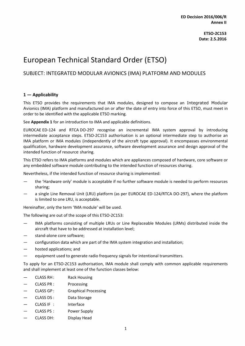
SUBJECT: INTEGRATED MODULAR AVIONICS (IMA) PLATFORM AND MODULES
1 — Applicability
This ETSO provides the requirements that IMA modules, designed to compose an Integrated Modular
Avionics (IMA) platform and manufactured on or after the date of entry into force of this ETSO, must meet in order to be identified with the applicable ETSO marking.
See Appendix 1 for an introduction to IMA and applicable definitions.
EUROCAE ED-124 and RTCA DO-297 recognise an incremental IMA system approval by introducing intermediate acceptance steps. ETSO-2C153 authorisation is an optional intermediate step to authorise an IMA platform or IMA modules (independently of the aircraft type approval). It encompasses environmental qualification, hardware development assurance, software development assurance and design approval of the intended function of resource sharing.
This ETSO refers to IMA platforms and modules which are appliances composed of hardware, core software or any embedded software module contributing to the intended function of resources sharing.
Nevertheless, if the intended function of resource sharing is implemented:
— the ‘Hardware only’ module is acceptable if no further software module is needed to perform resources sharing;
— a single Line Removal Unit (LRU) platform (as per EUROCAE ED-124/RTCA DO-297), where the platform is limited to one LRU, is acceptable.
Hereinafter, only the term ‘IMA module’ will be used.
The following are out of the scope of this ETSO-2C153:
— IMA platforms consisting of multiple LRUs or Line Replaceable Modules (LRMs) distributed inside the aircraft that have to be addressed at installation level;
— stand-alone core software;
— configuration data which are part of the IMA system integration and installation;
— hosted applications; and
— equipment used to generate radio frequency signals for intentional transmitters.
To apply for an ETSO-2C153 authorisation, IMA module shall comply with common applicable requirements and shall implement at least one of the function classes below:
— CLASS RH : Rack Housing
— CLASS PR : Processing
— CLASS GP : Graphical Processing
— CLASS DS : Data Storage
— CLASS IF : Interface
— CLASS PS : Power Supply
— CLASS DH : Display Head
ED Decision 2016/006/R Annex II
ETSO-2C153
Date: 2.5.2016
2
See Appendix 2 for common requirements and definitions of function classes.
An IMA module can also be compliant with a combination of MPS classes. In this case, the IMA module will be marked with all the classes it covers. However, as soon as a manufacturer voluntarily applies for an ETSO-2C153 authorisation, all the classes for which the intended function is implemented shall be compliant.
Example: A single LRU platform will be authorised as an ‘ETSO-2C153 CLASS PR + DS + IF’ if the intended function of resource sharing is implemented on processing, data storage and interface.
For an ETSO-2C153 CLASS DH authorisation, the IMA module shall be compliant with the requirements of ETSO-C113(*) ‘Airborne Multipurpose Electronic Displays’. The IMA module shall be marked with both ETSO-2C153 CLASS DH and ETSO-C113.
(*) Pleasa refer to the most recent C113 revision applicable.
2 — Procedures 2.1. — General Applicable procedures are detailed in Subpart A of CS-ETSO. Data to be submitted to the European Aviation Safety Agency (EASA) (hereinafter referred to as ‘the Agency’) are defined in Subpart O of Annex I (Part-21) to Regulation (EU) No 748/2012 and in Subpart A of CS-ETSO.
2.2 — Specific
Additional data which shall be submitted to the Agency by IMA modules manufacturers are specified in Appendix 3, including data required by ED-124 Task 1 (See paragraph 3.2.2.1 below).
3 — Technical Conditions 3.1 — Basic 3.1.1 — Minimum Performance Standard See Appendix 2.
3.1.2 — Environmental Standard See CS-ETSO Subpart A, paragraph 2.1 and Appendix 4.
3.1.3 — Computer Software See CS-ETSO Subpart A, paragraph 2.2.
3.1.4 — Airborne Electronic Hardware See CS-ETSO Subpart A, paragraph 2.3.
3.2 — Specific 3.2.1 — Failure Condition Classification It is recognised that IMA modules may be developed independently of specific installation projects and of future hosted aircraft functions, thus preventing the possibility to define the level of the aircraft failure condition, which is out of the scope of this ETSO.
However, the module architecture and development will be driven by generic failure conditions. These can be considered as assumptions, which will contribute to determin the Development Assurance Level (DAL) allocation as per CS-ETSO Subpart A, paragraph 2.4.
The assumed failure conditions and the resulting DAL are characterisation items and shall be documented in the installation manual and Declaration of Design and Performance (DDP).
Qualitative and safety mechanisms requirements for each class are specified in the Minimum Performance Specification in Appendix 2.
3.2.2 — Specific development and installation requirements 3.2.2.1 — Development process
ED Decision 2016/006/R Annex II
ETSO-2C153
Date: 2.5.2016
3
EUROCAE ED-124/RTCA DO-297 ‘Integrated Modular Avionics (IMA) Development Guidance and Certification Considerations’ contains guidance for IMA developers, application developers, integrators, certification applicants, and those involved in the approval and continuing airworthiness of IMA systems in civil certification projects.
In the frame of ETSO-2C153, the development of IMA modules or platforms shall meet the objectives of the EUROCAE ED-124/RTCA DO-297 guidance related to Task 1 (Table A-1 ‘Objectives’) except as constrained below:
Table A-1,Objective 8 is:
o applicable to a Single LRU platform; and
o partially applicable to an IMA module for intrinsic validation and verification activities. (i.e. excluding 4.2.1 h)
Note: for Table A-1, Objective 8, the column ‘doc ref’ refers to 5.3 and 5.4, which are detailing objectives with applicability per Task 1 of ED-124 (See Tables 5 and 6).
3.2.2.2 — Installation consideration
The ETSO-2C153 IMA module is by definition an incomplete system.
A definition of activities to be performed to properly use the ETSO-2C153 IMA module shall be defined for the installer. Associated test procedures to check that the authorised IMA module is properly installed shall also be documented in the installation manual in order to allow the integrator to perform integration of applications hosted on IMA platforms/modules and their installation on aircraft as per applicable guidance.
4 — Marking 4.1 — General Marking is detailed in Paragraph 1.2 of CS-ETSO, Subpart A.
4.2 — Specific The part shall be permanently and legibly marked with the intended function class(es) as defined in Paragraph 1 of this ETSO. This information shall be on the ETSO nameplate or in close proximity to the nameplate.
Note: An ETSO-2C153 marking does not cover IMA-hosted applications and IMA configuration which are software parts not covered by this ETSO.
5 — Availability of Referenced Document Please see paragraph 3 of CS-ETSO, Subpart A.
ED Decision 2016/006/R Annex II
ETSO-2C153
Date: 2.5.2016
A1-1
APPENDIX 1
INTEGRATED MODULAR AVIONICS (IMA) OVERVIEW, DEFINITION AND EXAMPLES
This Appendix provides:
— Chapter 1: an overview of Integrated Modular Avionics (IMA);
— Chapter 2: applicable definitions;
— Chapter 3: a definition of Minimum Performance Specification (MPS) classes; and
— Chapter 4: examples of IMA platforms using IMA modules.
Chapter 1: Integrated Modular Avionics overview
In this ETSO, Integrated Modular Avionics (IMA) is defined according to EUROCAE ED-124 (equivalent to the RTCA DO-297):
Integrated modular avionics (IMA): is a shared set of flexible, reusable, and interoperable hardware and software resources that, when integrated, form a platform that provides services, designed and verified to meet a defined set of safety and performance requirements, to host applications performing aircraft functions.
The IMA architecture integrates many aircraft functions on the same platform. Those functions are provided by several hosted applications that have historically been contained in functionally and physically separated ‘boxes’ or LRUs.
IMA platforms are composed of modules which are designed to be reusable in order to reduce development costs and occasionally facilitate certification programmes. Some modules provide only mechanical, possibly cooling and electrical power supply functions. Others include core software and associated computing capabilities.
The IMA modules are usually both generic and configurable, therefore, the same platform could be used on different aircraft models.
Chapter 2 — Applicable definitions Legend
— [ED-124]: Definitions from EUROCAE ED-124 (equivalent to RTCA DO-297).
— [2C153]: Definitions provided or adjusted in the frame of the ETSO.
Aircraft Function [ED-124]: The capability of the aircraft that may be provided by the hardware and software of the systems on the aircraft. Application [ED-124]: Software and/or application-specific hardware with a defined set of interfaces that, when integrated with the platform, performs a function. Cabinet [2C153]: Result of the integration of hardware modules mounted within one rack.
ED Decision 2016/006/R Annex II
ETSO-2C153
Date: 2.5.2016
A1-2
Characterisation item [2C153]: Identified module characteristics towards which the IMA module developer needs to determine the module performance, with full verification and documentation in the user guide/installation manual as appropriate. Component [ED-124]: A self-contained hardware, software part, database or combination thereof that is configuration-controlled. A component does not provide an aircraft function by itself. Configuration data [ED-124]: See Paragraph 3.7.1. Core Software [ED-124]: The operating system and support software that manage resources to provide an environment in which applications can be executed. Core software is a necessary component of a platform and is typically comprised of one or more modules (such as, for example, libraries, drivers, kernel, data-loading, boot, etc.). IMA Platform [ED-124]: A module or group of modules, including core software, which manage resources in a manner sufficient to support at least one application. IMA hardware resources and core software are designed and managed in a way that provides computational, communication and interface capabilities for hosting at least one application. Platforms by themselves do not provide any aircraft functionality. The IMA platform may be accepted independently of hosted applications. IMA System [ED-124]: It consists of (an) IMA platform(s) and a defined set of hosted applications. LRM (Line Replaceable Module) [2C153]: An IMA platform element identified in aircraft configuration and replaceable by aircraft line maintenance to restore the aircraft into an operational ready condition. An IMA LRM is a stand-alone equipment which does not provide any aircraft function until hosted applications are integrated. LRU (Line Replaceable Unit) [2C153]: An element supporting an aircraft function identified in aircraft configuration and replaceable by aircraft line maintenance to restore the aircraft into an operational ready condition. An LRU is usually a stand-alone equipment such as a radio, a Flight Management Computer or any kind of functional equipment. IMA Module [2C153]: A component or collection of components that may be hardware or a combination of hardware and software, which provide resources to the IMA-hosted applications. Software application and module configuration data are not covered by this definition. Modules may be distributed across the aircraft or may be co-located. Operating System[ED-124]:
1) The same as executive software.
2) The software kernel that services only the underlying hardware platform.
3) Software that directs the operations of a computer, resource allocation and data management, controlling and scheduling the execution of computer-hosted applications, managing memory, storage, input/output, and communication resources.
Rack [2C153]: A physical package able to contain at least two hardware modules, which may provide partial protection from environmental effects (shielding) and may enable installation on and removal of the mounted modules from the aircraft without physically altering other aircraft systems or equipment.
ED Decision 2016/006/R Annex II
ETSO-2C153
Date: 2.5.2016
A1-3
Resources/Shared resources [ED-124]: Any object (processor, memory, software, data, etc.) or component used by an IMA platform or application. A resource may be shared by multiple applications or dedicated to a specific application. A resource may be physical (a hardware device) or logical (a piece of information). Support software [2C153]: Embedded software necessary as a complement to the operating system to provide general services such as contributing to the intended function of resources sharing, handling hardware, drivers, software loading, health monitoring, boot strap, etc. Unit [2C153]: Set of physical components (hardware and/or software) inside an equipment in charge of providing a resource.
Usage Domain [2C153]: The usage domain of an IMA module is defined as an exhaustive list of conditions (such as configuration settings, usage rules etc.) to be respected by the user(s) to ensure that the IMA module continues to meet the performance characteristics and requirements of the ETSO Minimum Performance Standard. Compliance with usage domain ensures that:
— the module is compliant with its functional, performance, safety and environmental requirements specified for all implemented intended functions;
— the module characteristics documented in the User Guide (as required by Appendix 2) are guaranteed by manufacturer; and
— the module is compliant with the applicable airworthiness requirements (including continuing airworthiness aspects). (*)
(*) Note: in the context of this IMA modules/platforms ETSO standard, this last sentence refers to requirements as described in Section 2 of CS-ETSO Subpart A.
Chapter 3 — Definition of intended function classes
To apply for an ETSO-2C153 authorisation, the IMA module shall comply with applicable common requirements and implement at least one Intended Function Class. As soon as a manufacturer applies for an ETSO-2C153 authorisation, all the classes for which the Intended Function is implemented shall be compliant. CLASS RH: Rack Housing For ETSO-2C153 Class RH: 1.3.RH.1: The IMA module is a physical package able to contain at least two hardware modules that may provide protection from environmental effects (shielding, etc.) and enable installation and removal of those module(s) from the aircraft without physically altering other aircraft systems or equipment. 1.3.RH.2: The IMA module may be a simple mechanical enclosure, or it may incorporate communication interfaces, backplanes for data and power supplies, active cooling or any combination of these features. 1.3.RH.3: The IMA module does not offer the capability to host applications unless combined with a Class PR approval. 1.3.RH.4: The IMA module may be configurable. CLASS PR: Processing
ED Decision 2016/006/R Annex II
ETSO-2C153
Date: 2.5.2016
A1-4
For ETSO-2C153 Class PR: 1.3.PR.1: The IMA module contains a processing component, a memory component, interface devices and associated Core Software which constitute one or several Processing Unit(s). Note: Containing memory components or interfaces devices does not lead automatically to having class DS and/or IF in the certification basis; DS or IF classes need to be applied for only if concurrent access to these interface or data storage resources is offered as a shared resource (as described in Class DS and IF). 1.3.PR.2: The intended function of such an IMA module is to share Processing, Data and Information between at least two hosted applications, modules and/or components. 1.3.PR.3: The IMA module offers the capability to host applications. 1.3.PR.4: The IMA module may be an association of hardware and Core Software.
— Hardware may (or may not) contain resident (not field-loadable) software to enable electronic part marking and/or future loading of Field-Loadable Software parts.
— Core Software may be resident or a Field-Loadable Software Part.
1.3.PR.5: The IMA module may be configurable. CLASS GP: Graphical Processing For ETSO-2C153 Class GP: 1.3.GP.1: The IMA module contains a graphical engine component and an optional video engine component, memories, interfaces and potentially associated Core Software which constitute one or several Graphical Unit(s). 1.3.GP.2: The intended function of such an IMA module is to share graphics and optional video signal processing between at least two hosted applications, modules and/or components. 1.3.GP.3: The IMA module does not offer the capability to host software applications unless combined with a Class PR approval. 1.3.GP.4: The IMA module may be an association of hardware and Core Software.
— Hardware may (or may not) contain resident (not field-loadable) software to enable electronic part marking and/or future loading of Field-Loadable Software parts.
— Core Software may be resident or a Field-Loadable Software Part 1.3.GP.5: The IMA module may be configurable. CLASS DS: Data Storage For ETSO-2C153 Class DS: 1.3.DS.1: The IMA module contains memory (volatile or non-volatile), an interface component and potentially associated Core Software which constitute one or several Data Storage Unit(s).
ED Decision 2016/006/R Annex II
ETSO-2C153
Date: 2.5.2016
A1-5
1.3.DS.2: The intended function of such an IMA module is to share stored data (e.g. databases, files, etc.) between several applications, modules and/or components. 1.3.DS.3: The IMA module does not offer the capability to host applications, unless combined with a Class PR approval. 1.3.DS.4: The IMA module may be an association of hardware and a Core Software.
— Hardware may (or may not) contain resident (not field-loadable) software to enable electronic part marking and/or future loading of Field-Loadable Software parts.
— Core Software may be resident or a Field-Loadable Software Part. 1.3.DS.5: The IMA module may be configurable. CLASS IF: Interface For ETSO-2C153 Class IF: 1.3.IF.1: The IMA module contains input/output component(s) and potentially associated Core Software which constitute one or several Interface Unit(s). These interfaces can be discrete, analogue, a serial interface, a digital bus, etc.. 1.3.IF.2: The intended function of such an IMA module is to share information between several aircraft functions or applications. 1.3.IF.3: The IMA module does not offer the capability to host applications unless combined with a Class PR approval. 1.3.IF.4: The IMA module may be an association of hardware and a Core Software.
— Hardware may (or may not) contain resident (not field-loadable) software to enable electronic part marking and/or future loading of Field-Loadable Software parts.
— Core Software may be resident or a Field-Loadable Software Part. 1.3.IF.5: The IMA module may be configurable. CLASS PS: Power Supply For ETSO-2C153 Class PS: 1.3.PS.1: The IMA module contains a set of components (hardware and/or software) which constitute one or several Power Supply Unit(s) in charge of managing power supply. 1.3.PS.2: The intended function of such an IMA module installed into a rack (Class RH module) is to provide power supply from an airborne electrical network to one or more hardware modules embedded into the same rack.
ED Decision 2016/006/R Annex II
ETSO-2C153
Date: 2.5.2016
A1-6
1.3.PS.3: The IMA module does not offer the capability to host applications unless combined with a Class PR approval. 1.3.PS.4: The IMA module may be configurable. 1.3.PS.5: The IMA module may be an association of hardware and a Core Software.
— Hardware may (or may not) contain resident (not field-loadable) software to enable electronic part marking and/or future loading of Field-Loadable Software parts.
— Core Software may be resident or a Field-Loadable Software Part. CLASS DH: Display Head For ETSO-2C153 Class DH: 1.3.DH.1: The IMA module contains a set of components (hardware and/or software) in charge of managing a displayed area which constitutes one or several Display Unit(s). 1.3.DH.2: The intended function of such an IMA module is to offer the capability to depict graphical information received from IMA Application(s), component(s) and/or module(s) on one Display Area. 1.3.DH.3: The IMA module does not offer the capability to host applications unless combined with a Class PR approval. 1.3.DH.4: The IMA module may be an association of hardware and a Core Software.
— Hardware may (or may not) contain resident (not field-loadable) software to enable electronic part marking and/or future loading of Field-Loadable Software parts.
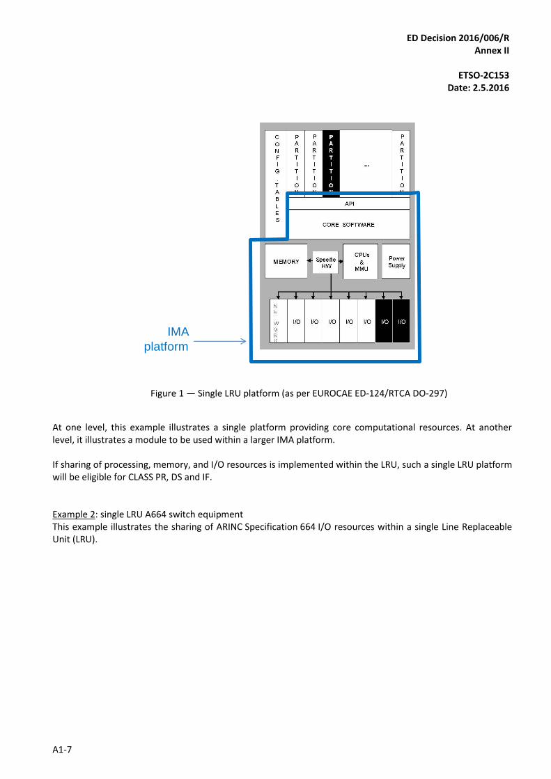
— Core Software may be resident or a Field-Loadable Software Part. 1.3.DH.5: The IMA module may be configurable. Chapter 4 — Example of an IMA platform using IMA modules EUROCAE ED-124/RTCA DO-297 contains some examples relating to the definition of the IMA module and platform, which can be completed by some additional examples related to Chapter 3 ‘Definitions’. Example 1: single LRU platform (as per EUROCAE ED-124/RTCA DO-297) This example illustrates the sharing of computational and Input/Output (I/O) resources within a single Line Replaceable Unit (LRU). Such IMA system key characteristics include:
— hosting of multiple applications (not part of the IMA platform);
— platform configuration data and data loading; and
— defined API between the IMA platform and hosted applications.
ED Decision 2016/006/R Annex II
ETSO-2C153
Date: 2.5.2016
A1-7
IMA
platform
Figure 1 — Single LRU platform (as per EUROCAE ED-124/RTCA DO-297)
At one level, this example illustrates a single platform providing core computational resources. At another level, it illustrates a module to be used within a larger IMA platform.
If sharing of processing, memory, and I/O resources is implemented within the LRU, such a single LRU platform will be eligible for CLASS PR, DS and IF. Example 2: single LRU A664 switch equipment This example illustrates the sharing of ARINC Specification 664 I/O resources within a single Line Replaceable Unit (LRU).

ED Decision 2016/006/R Annex II
ETSO-2C153
Date: 2.5.2016
A1-8
Figure 2 — Example of an architecture based on two ETSO-2C153 class IF modules implementing each
an ARINC 664 switch.
In this architecture, the two ETSO-2C153 class IF modules switch A664 frames, providing each of the subscriber a shared access to the network. Network subscribers can be other ETSO-2C153 modules as the lower row of modules shows, or non-IMA equipment (top row) such as displays/radio transceivers. If sharing of ARINC Specification 664 I/O resources is implemented within the LRU, such a single LRU platform shall be eligible for CLASS IF. Example 3: IMA modules installed in a Rack Module (Line Replaceable Module)
Rack
2 C153CLASS RH
2C153CLASS PR+IF
Rack
LRM1
LRM2
LRM3
LRM2
LRM4
2C153CLASS GP
2C153CLASS PS
Non ETSOModule
2C153 C
lass P
R
LRM
2C153 C
lass I
F
LRM
2C153 C
lass P
R
LRM
LRU B LRU C LRU DLRU A
2C153 C
lass P
S
LRM
2C153 C
lass P
R
LRM
2C153 C
lass I
F
LRM
2C153 C
lass P
R
LRM
2C153 C
lass P
S
LRM
2C153 Class IF A664 Switch
2C153 Class IF A664 Switch
Virtual Link (see ARINC 664) between two subscribers, switched by the 2C153 class IF modules
ED Decision 2016/006/R Annex II
ETSO-2C153
Date: 2.5.2016
A1-9
Figure 3 — IMA modules installed in a Rack Module
This example illustrates the sharing of resources within several single Line Replaceable Modules (LRM) installed in a Rack:
— a Rack is an IMA module and will be eligible for CLASS RH;
— LRM 1 provides shared Processing and Input/Output and shall be eligible for CLASS PR+IF;
— LRM 2 provides shared Graphical Processing and shall be eligible for CLASS GP;
— LRM 3 provides shared Power Supply to LRM embedded into the same rack, and shall be eligible for CLASS PS; and
— LRM 4 does not provide shared resources. This module shall be considered as a non-ETSO-2C153 module.
All these modules are considered Parts.
ED Decision 2016/006/R Annex II
ETSO-2C153
Date: 2.5.2016
A2-1
APPENDIX 2
INTEGRATED MODULAR AVIONICS (IMA) MODULE MINIMUM PERFORMANCE SPECIFICATION (MPS)
This Appendix provides a Specific Minimum Performance Specification for IMA modules. Principle
An IMA module is composed of hardware components or hardware and software components performing the intended function(s) whose minimum performance requirements are specified in this Appendix.
This Minimum Performance Specification (MPS) is structured as a common-requirements section and a set of classes specifying IMA module intended functions:
— COMMON: Minimum Performance Specification applicable whatever IMA module and whatever the implemented intended function class(es);
— CLASS RH: Rack Housing intended function;
— CLASS PR: Processing intended function;
— CLASS GP: Graphical Processing intended function;
— CLASS DS: Data Storage intended function;
— CLASS IF: Interface intended function;
— CLASS PS: Power Supply intended function; and
— CLASS DH: Display Head intended function. To apply for an ETSO-2C153 authorisation, the IMA module shall comply with a common Minimum Performance Standard and implement at least one Intended Function Class as defined in this Appendix. When applying for an ETSO-2C153 authorisation, the applicant shall include in the certification basis all classes for which the intended function is implemented in the IMA module/platform. Naming convention This document contains ‘shall’, ‘should’ and ‘may’ statements with the following meanings:
— the use of word ‘shall’ indicates a mandated criterion, i.e. compliance with the criterion is mandatory and no alternative may be applied;
— the use of word ’should’ (and phrases such as ‘It is recommended that...’, etc.) indicate that though the procedure or criterion is regarded as the preferred option, alternative procedures, specifications or criteria may be applied, provided that the manufacturer, installer or tester can provide information or data to adequately support and justify the alternative;
ED Decision 2016/006/R Annex II
ETSO-2C153
Date: 2.5.2016
A2-2
— the use of word ‘may’ indicates that though the criterion is regarded as the preferred option, alternative criteria may be applied. In such cases, alternatives should be identified in appropriate approval plans and agreement sought from the approval authority; and
Verification Procedures For verification procedures, the following definitions and symbols are used in this Appendix: Analysis (A)
Analysis is the method of verification which consists in comparing design with known scientific and technical principles, technical data, or procedures and practices to validate that the proposed design will meet the specified functional or performance requirements.
Demonstration (D)
Demonstration is the method of verification where qualitative versus quantitative validation of a requirement is made during a dynamic test of the system/equipment. In general, software functional requirements are verified by demonstration since their functionality must be observed through some secondary media.
Inspection (I)
Inspection is the method of verification to determine compliance with requirements and consists primarily of visual observations or mechanical measurements of the system/equipment, physical location, or technical examination of the engineering support documentation.
Test (T)
Test is the method of verification that will exercise equipment functions and measure system/equipment performance under a specific configuration and load conditions and after the controlled application of known stimuli. Quantitative values are measured, compared against previously predicated success criteria, and then evaluated to determine the degree of compliance.
Y The test is mandated under the indicated conditions.
m/n Either verification method ‘m’ or verification method ‘n’ may be used to verify the requirement (i.e. D/A can be verified by Demonstration or Analysis).
m+n
Both verification methods must be used to verify the requirement (i.e. D+A means that the requirement must be verified by Demonstration and Analysis).
ED Decision 2016/006/R Annex II
ETSO-2C153
Date: 2.5.2016
A2.1-1
APPENDIX 2.1
INTEGRATED MODULAR AVIONICS (IMA) MODULE MINIMUM PERFORMANCE SPECIFICATION (MPS)
COMMON: Applicable to all IMA modules
1. Purpose and scope
This section contains a set of Minimum Performance Standards (MPS) applicable to any IMA module and to any implemented intended function class(es). In the following, the term ‘concurrent items’ designates the items (applications, for example) that use the shared resource of the IMA module. Depending on the module class, it means ‘processing element’ for PR class, ‘thread’ for GP, IF and DH class, ‘data storage element’ for DS class, and ‘power rail’ for PS class.
2. Requirements
Functional requirements common to all classes 2.1.
CO.a) The IMA shall implement at least one Function Class.
The following requirements of this paragraph are applicable to all classes with some exception as described below:
CO.b) Except for the housing function (F1) of class RH (see Appendix 2.2, paragraph 2.1.1), the IMA module shall provide at least the following control features to react to detected failures:
a. disable, and
b. reset.
CO.c) Except for the Housing function (F1) of class RH (see Appendix 2.2, paragraph 2.1.1), each IMA module shall provide health management and reporting capability.
CO.d) Except for the ousing function (F1) of class RH (see Appendix 2.2 , paragraph 2.1.1), the health management and reporting function shall detect, isolate, contain and report faults (in the shared resources and other resources) that could adversely affect applications using the module resources or the resources themselves.
CO.e) Except for class RH, robust partitioning (as per EUROCAE ED-124/RTCA DO-297) between ‘concurrent items’ sharing the resource shall be ensured by the IMA module.
CO.f) Except for class RH, robust partitioning shall not rely on any required behavior of any aircraft function or hosted application (as per EUROCAE ED-124/RTCA DO-297, Section 3.5c).
CO.g) Except for class RH, the potential breaches in robust partitioning shall be identified. An appropriate process and means should be implemented to ensure that such failures which result or may result in an unsafe condition are detected and reported.
ED Decision 2016/006/R Annex II
ETSO-2C153
Date: 2.5.2016
A2.1-2
CO.h) Except for class RH, the IMA module shall implement a fault containment mechanism to prevent fault propagation between ‘concurrent items’ using the shared-resource elements and between other IMA modules.
CO.i) Reserved.
CO.j) Except for the Housing function (F1) of class RH (see Appendix 2.2, paragraph 2.1.1), the interface between the ‘concurrent items’ and the shared resource should conform to the characteristics as described by a standard (ARINC specifications 653, 664, and 600, for example).
Characterisation requirements 2.2.
CO.k) Each item of the characterisation shall be documented in the User Guide/Installation Manual as appropriate.
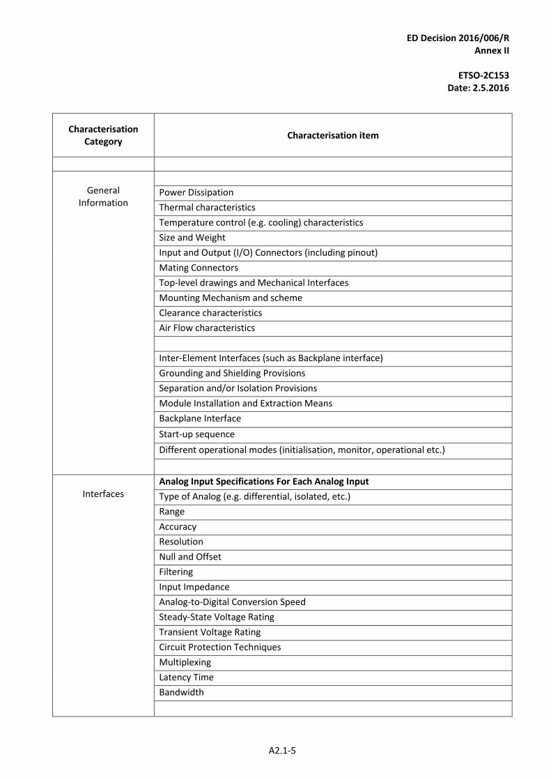
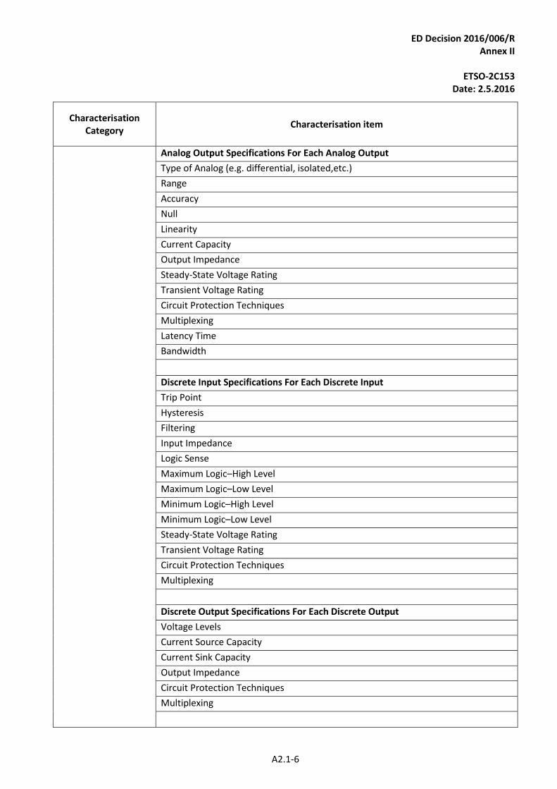
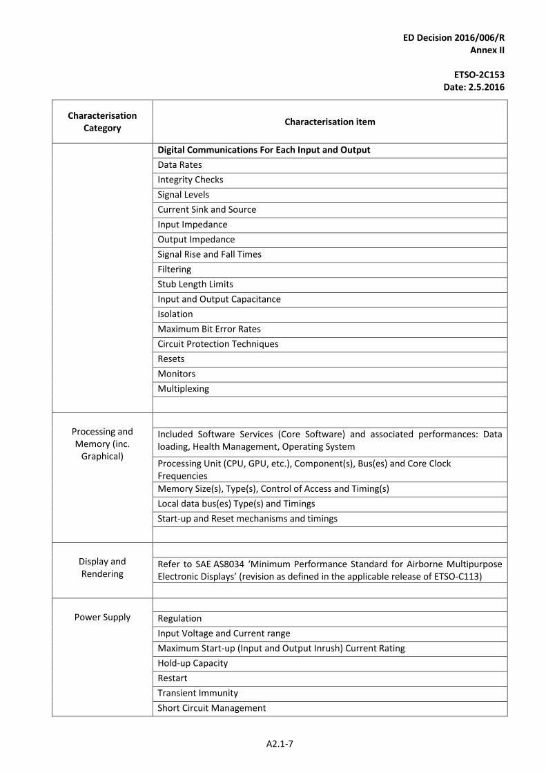
CO.l) The IMA module specification shall be characterised based on items in the table below (Figure 4: IMA module Characterisation Categories) and on the characterisation requirements identifying additional characterisation items specific to each functional class (defined in Appendix 2 — Class RH, PR, GP, DS, IF, PS, and DH).
CO.m) Quantifiable characterised items shall be quantified in terms of minimum, typical (when relevant) and maximum values and the associated accuracy.
Note: Influence of environmental or abnormal conditions should be considered when relevant.
CO.n) The characterisation of the IMA module shall be correct and complete. Completeness is achieved when all shared features of the IMA module have been characterised.
CO.o) The characterisation shall identify the valid usage domain of the IMA module.
CO.p) The characterisation shall provide all constraints on the usage domain and on the installation (including limitations and activities) to be respected by the users.
CO.q) The characterisation shall provide the list of types of shared-resource elements, the associated attributes, their configurability and their performances, and their associated limit of use.
CO.r) The characterisation shall include at least the following characteristics of the core software/programmable hardware:
a. identification of the core software component(s)/programmable hardware (if any);
b. the IMA module functionality, performance and safety requirements supported by the core software/programmable hardware;
c. external interfaces and associated data coupling/control-coupling information;
d. integration and loading procedure(s); and
e. development assurance level(s).
CO.s) When the IMA module offers the capability to host software, the characterisation shall provide any data needed to evaluate the Worst Case Execution Time (WCET) of each concurrent item sharing the IMA module resource.
CO.t) The performances of each shared-resource management mechanism including monitoring shall be characterised, in particular the range, timing aspects, transients, etc..
CO.u) For at least the following failure modes, the failure rate shall be provided:
a. loss of the IMA module;
ED Decision 2016/006/R Annex II
ETSO-2C153
Date: 2.5.2016
A2.1-3
b. erroneous behavior of the IMA module;
c. loss of the shared-resource element; and
d. erroneous behavior of the shared-resource element.
CO.v) The characterisation shall include the monitoring coverage rate (PBIT, CBIT, etc.) for the identified failure modes of the IMA module (including shared and unshared resources, sharing mechanisms and robust partitioning mechanisms).
CO.w) The characterisation shall address the safety aspects of bad sequencing, delay, corruption and impersonation, where applicable.
CO.x) The following health monitoring items shall be included in the characterisation:
a. interface rules, constraints (including limitations) to be respected by the users;
b. list of Health Monitoring services;
c. list of monitored components, monitored services, monitored interfaces;
d. response to each type of fault;
e. fault reporting attributes (reporting refers to internal logging, indication to applications using the shared resources, indication outside of the module); and
f. the configuration attributes, if any.
CO.y) If the IMA module is configurable, the characterisation shall include, in addition, the following items:
a. the authorised configuration parameters (including range, type and definition of combined parameters) in the usage domain; and
b. the configuration activities to be conducted (including configuration procedures, means and tools) by the user during application development (EUROCAE ED-124 — Task 2) and IMA system integration (EUROCAE ED-124 — Task 3 and 4).
CO.z) If some tools are required for installation, these tools shall be characterised according to the following:
a. identification;
b. the user’s manuals of the tools;
c. the activities related to those tools to be conducted during application development (EUROCAE ED-124 — Task 2) and IMA system integration (EUROCAE ED-124 — Task 3 and 4);
d. the proposed associated qualification credits that could be granted to the user of the tools;
e. the category of the tool and the Development Assurance Level of the tool (if any) as defined in the applicable Software Development assurance guidance (see Section 2.2 of CS-ETSO, Subpart A,); and
f. limitations and Open Problem Report (if any) on Tools that could affect the tool qualification credit and require analysis by the user.
CO.aa) The compatibility and mixability information between hardware, software, tools and usage domain shall be part of the characterisation. This characterisation shall address at least the following:
ED Decision 2016/006/R Annex II
ETSO-2C153
Date: 2.5.2016
A2.1-4
a. how the authorised mixed combinations are verified;
b. the compatibility assessment process with authorised mixed combinations of interfacing modules (external mixability);
c. any preventative measures (design or procedures) to be developed by the user to prevent incorrect module combinations or software loads; and
d. information to be provided to maintenance personnel.
CO.bb) The control features (disable, reset, reload, etc.) of the IMA module for reacting to detected failures shall be characterised.
ED Decision 2016/006/R Annex II
ETSO-2C153
Date: 2.5.2016
A2.1-5
Characterisation Category
Characterisation item
General
Information
Power Dissipation
Thermal characteristics
Temperature control (e.g. cooling) characteristics
Size and Weight
Input and Output (I/O) Connectors (including pinout)
Mating Connectors
Top-level drawings and Mechanical Interfaces
Mounting Mechanism and scheme
Clearance characteristics
Air Flow characteristics
Inter-Element Interfaces (such as Backplane interface)
Grounding and Shielding Provisions
Separation and/or Isolation Provisions
Module Installation and Extraction Means
Backplane Interface
Start-up sequence
Different operational modes (initialisation, monitor, operational etc.)
Interfaces
Analog Input Specifications For Each Analog Input
Type of Analog (e.g. differential, isolated, etc.)
Range
Accuracy
Resolution
Null and Offset
Filtering
Input Impedance
Analog-to-Digital Conversion Speed
Steady-State Voltage Rating
Transient Voltage Rating
Circuit Protection Techniques
Multiplexing
Latency Time
Bandwidth
ED Decision 2016/006/R Annex II
ETSO-2C153
Date: 2.5.2016
A2.1-6
Characterisation Category
Characterisation item
Analog Output Specifications For Each Analog Output
Type of Analog (e.g. differential, isolated,etc.)
Range
Accuracy
Null
Linearity
Current Capacity
Output Impedance
Steady-State Voltage Rating
Transient Voltage Rating
Circuit Protection Techniques
Multiplexing
Latency Time
Bandwidth
Discrete Input Specifications For Each Discrete Input
Trip Point
Hysteresis
Filtering
Input Impedance
Logic Sense
Maximum Logic–High Level
Maximum Logic–Low Level
Minimum Logic–High Level
Minimum Logic–Low Level
Steady-State Voltage Rating
Transient Voltage Rating
Circuit Protection Techniques
Multiplexing
Discrete Output Specifications For Each Discrete Output
Voltage Levels
Current Source Capacity
Current Sink Capacity
Output Impedance
Circuit Protection Techniques
Multiplexing
ED Decision 2016/006/R Annex II
ETSO-2C153
Date: 2.5.2016
A2.1-7
Characterisation Category
Characterisation item
Digital Communications For Each Input and Output
Data Rates
Integrity Checks
Signal Levels
Current Sink and Source
Input Impedance
Output Impedance
Signal Rise and Fall Times
Filtering
Stub Length Limits
Input and Output Capacitance
Isolation
Maximum Bit Error Rates
Circuit Protection Techniques
Resets
Monitors
Multiplexing
Processing and Memory (inc.
Graphical)
Included Software Services (Core Software) and associated performances: Data loading, Health Management, Operating System
Processing Unit (CPU, GPU, etc.), Component(s), Bus(es) and Core Clock Frequencies
Memory Size(s), Type(s), Control of Access and Timing(s)
Local data bus(es) Type(s) and Timings
Start-up and Reset mechanisms and timings
Display and Rendering
Refer to SAE AS8034 ‘Minimum Performance Standard for Airborne Multipurpose Electronic Displays’ (revision as defined in the applicable release of ETSO-C113)
Power Supply
Regulation
Input Voltage and Current range
Maximum Start-up (Input and Output Inrush) Current Rating
Hold-up Capacity
Restart
Transient Immunity
Short Circuit Management
ED Decision 2016/006/R Annex II
ETSO-2C153
Date: 2.5.2016
A2.1-8
Characterisation Category
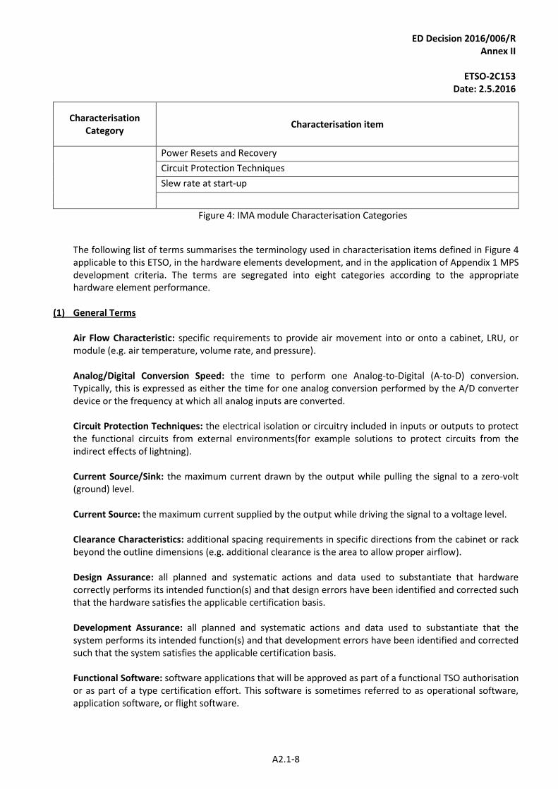
Characterisation item
Power Resets and Recovery
Circuit Protection Techniques
Slew rate at start-up
Figure 4: IMA module Characterisation Categories
The following list of terms summarises the terminology used in characterisation items defined in Figure 4 applicable to this ETSO, in the hardware elements development, and in the application of Appendix 1 MPS development criteria. The terms are segregated into eight categories according to the appropriate hardware element performance.
(1) General Terms
Air Flow Characteristic: specific requirements to provide air movement into or onto a cabinet, LRU, or module (e.g. air temperature, volume rate, and pressure). Analog/Digital Conversion Speed: the time to perform one Analog-to-Digital (A-to-D) conversion. Typically, this is expressed as either the time for one analog conversion performed by the A/D converter device or the frequency at which all analog inputs are converted. Circuit Protection Techniques: the electrical isolation or circuitry included in inputs or outputs to protect the functional circuits from external environments(for example solutions to protect circuits from the indirect effects of lightning). Current Source/Sink: the maximum current drawn by the output while pulling the signal to a zero-volt (ground) level. Current Source: the maximum current supplied by the output while driving the signal to a voltage level. Clearance Characteristics: additional spacing requirements in specific directions from the cabinet or rack beyond the outline dimensions (e.g. additional clearance is the area to allow proper airflow). Design Assurance: all planned and systematic actions and data used to substantiate that hardware correctly performs its intended function(s) and that design errors have been identified and corrected such that the hardware satisfies the applicable certification basis. Development Assurance: all planned and systematic actions and data used to substantiate that the system performs its intended function(s) and that development errors have been identified and corrected such that the system satisfies the applicable certification basis. Functional Software: software applications that will be approved as part of a functional TSO authorisation or as part of a type certification effort. This software is sometimes referred to as operational software, application software, or flight software.
ED Decision 2016/006/R Annex II
ETSO-2C153
Date: 2.5.2016
A2.1-9
Functional TSO: a TSO with a defined functionality (e.g. a Global Positioning System (GPS), TSO-C129a). TSO-C153 is not considered a functional TSO, because IMA hardware elements typically do not have system-level functionality. Grounding/Shielding Provisions: the electrical and/or mechanical details of the design which provide grounding of the element or shield connections. These are the design details usually associated with the Radio Frequency emission and susceptibility protection of the system. Hardware Element: in this TSO, a hardware element is (1) a hardware module, or (2) cabinets or racks that host hardware modules. Note: this definition may differ from the terminology used in other documents (e.g. RTCA/DO-254). Inter-Element Connections: the connector type specification and connector pin assignments specified to allow modules to be installed interchangeably in the cabinets or racks. Inter-Element Interfaces: the definition of the electrical signals, timing requirements, and protocols used to communicate among modules or elements with the cabinet or system. Module Extraction Means: the details of the mechanical design to enable removal of the module from the cabinet. Module Mounting Scheme: the details of the mechanical design used to secure each module into the cabinet or rack. Mounting Mechanism: the details of the mechanical mechanism(s) used to secure the module into the cabinet or rack of the aircraft. Multiplexing: the design technique where multiple inputs are individually switched to one receiver (for example, multiple digital communication buses switched to a serial receiver) or multiple outputs are individually supplied by the same circuit (for example, multiple analog outputs driven by one Digital-to-Analog converter through multiple sample-and-hold). Separation/Isolation Provisions: the electrical and/or mechanical details of the design which provide physical or electrical means of reducing interference from one element to another. Steady State Voltage Rating: the maximum voltage range that can be applied continuously to an input or output without resulting in damage. Transient Voltage Rating: the maximum voltage that can be applied for a short period of time to an input or output without resulting in damage. The maximum duration of the transient must be included.
(2) Analog Input/Output Terms Accuracy: the degree of conformity to the true value of the signal. This is usually expressed as a percentage of the reading or a percentage of the full-scale value of the signal. Current Capacity: the maximum amount of current that can be sinked or sourced by the circuit. Linearity: the error from the directly proportional expected signal value as the signal values vary over the entire range.
ED Decision 2016/006/R Annex II
ETSO-2C153
Date: 2.5.2016
A2.1-10
Null: the signal value(s) for which a value of zero is identified. This is usually shown as positive and negative voltage values. Offset: the indicated signal value (usually non-zero) when zero volts are applied. Range: the least and greatest operating voltage extremes (full scale) of the signal; the voltage extremes between which the signal value is valid. Resolution: the smallest measurable division of the numerical expression of the signal. This is usually identified as the number of binary bits used to express the signal value and/or the value in volts of the least significant binary bit (LSB).
(3) Discrete Input/Output Terms
Discrete Input: this is an input only two states. Typical examples are ‘ground or open’ and ’28-volt and open’ inputs. Discrete Output: an output only two states. Typical examples are ‘ground or open’ and ’28-volt and open’ outputs.
(4) Input Terms Hysteresis: the value of the input voltage lag when changing states. For example, if an input circuit has 0.2 volts of hysteresis and if the trip point is 2.0 volts, then the circuit will change state as the input voltage reaches 2.0 volts but will not revert back to the original state until the input voltage drops below 1.8 volts. Logic Sense: this is the functional interpretation of the discrete input states. A true or positive logic sense may identify the ‘ground’ state as ‘low’ or binary ‘0’. An inverse or negative logic sense may identify a ‘ground’ state as ‘high’ or binary ‘1’. Maximum Logic–High Level: the largest voltage value that can be applied to the input and that the circuit will interpret as ‘high’. Maximum Logic–Low Level: the largest voltage value that can be applied to the input and that the circuit will interpret as ‘low’. Minimum Logic–High Level: the smallest voltage value that can be applied to the input and that the circuit will interpret as ‘high’. Minimum Logic–Low Level: the smallest voltage value that can be applied to the input and that the circuit will interpret as ‘low’. Trip Point: this is the input voltage value at which the input circuitry changes state.
(5) Output Terms Current Sink Capacity: the maximum current by the output while pulling the signal to a zero-volt (ground) level (current flowing in the direction from the load to the element output).

ED Decision 2016/006/R Annex II
ETSO-2C153
Date: 2.5.2016
A2.1-11
Current Source Capacity: the maximum current supplied by the output while driving the signal to a voltage level (current flowing from the element output to the load). Voltage Levels: the minimum and maximum voltages for each state of the output. The ground point that is to be used as reference must be identified.
(6) Processor Terms
Backplane Interface: the definition of the electrical signals, buses, timing requirements, and protocols used to communicate among elements installed in a cabinet or rack. Interrupts: the signals to the processor that stops execution of an ongoing process or application. These signals indicate that there is a higher priority request of task or an asynchronous event is occurring. Memory Management Unit: a specialised control circuitry, sometimes integrated within the microprocessor, which performs predictive reads of instruction (prefetch) for use by the processor. It also may perform structured or prioritised control of specific sections of the memory. Monitors: specific circuits which observe the normal operation of the processing system and alert the processor or user to an abnormal condition. Examples are power supply monitors, which reset the processor when a voltage is outside of its tolerance, and activity monitors, which reset the processor when the processor does not perform a prescribed sequence. Reset Structure: the architectural details of the various signals that stop execution of an ongoing process, or software application and restarts the processor at a known state. Central Processing Unit (CPU) Throughput: a measure of the number of processor instructions performed by the CPU per unit of time.
(7) Power Supply Terms Hold-up Capacity: the capacity of the power supply to continue supplying output current after the input voltage drops below the minimum level. This is usually expressed as the time from the input voltage drop to the reset generated by the power supply. Input Voltage & Current: the input voltage is specified as nominal and acceptable variation values. The input current is specified as maximum steady state current. For peak current, please see under ‘Inrush Current’ below. Maximum Start-up (Inrush) Current Rating: the maximum input current when the power supply first becomes active as a result of the input voltage increase to the minimum level. Output Current Capacity: the continuously operating maximum current supplied for each output voltage. Power Monitors & Status Outputs: separate circuitry which checks the output voltage levels and current loading of the power supply. This circuitry will generate one or more binary signals that may be connected to the processor to alert it to the ‘out of spec’ condition. These binary signals may also force the power supply to shut down to prevent damage to power supply components.
ED Decision 2016/006/R Annex II
ETSO-2C153
Date: 2.5.2016
A2.1-12
Power Resets: a binary signal output from the power supply that is asserted when the output voltages are outside acceptable tolerances.
Regulation: the percentage of variation of the output voltages when subjected to changes in load, changes in temperature, and all input voltage transients and deviations. Restart: the ability of the power supply or other circuit to return to the normal operating mode when the input voltage returns to or above the minimum level or when the tripped monitor indicates that the ‘out-of-spec’ condition has returned to normal. Short Circuit Management: the circuitry that monitors for short circuits or overcurrent conditions in the power supply outputs. The results from this circuitry may shut down the affected output or the entire power supply. Transient Immunity: the ability of the power supply to continue operating normally during variations in the input voltage. This is usually expressed as the length of time and voltage level of the transient. Voltage Outputs & Tolerances: the voltage levels and tolerances of the outputs produced by the power supply.
(8) Digital Communication Terms
Data Rates: the number of data bits transmitted in a time period. This is usually expressed in thousands of bits per second (Kbps) or millions of bits per second (Mbps). Integrity Checks: the process that uses additional data accompanying the message information to validate that the message data was received without corruption or contamination. Examples are parity checks, checksums, data validity checks, and cyclic redundancy checks. Maximum Bit Error Rates: the largest number of bit errors allowed in a message transmission before the receiver invalidates its ability to receive data from that source. Monitors: separate circuitry that checks either the continuing operation of a transmitter, or that the receiver responds to input data. This circuitry will generate one or more binary signals that may be connected to the processor, alerting it to the ‘failed’ condition. Resets: conditions that result in the receiver or transmitter stopping operation, clearing all data, and restarting. Signal Levels: the minimum and maximum voltages for each state of the input or output. Typically, tolerances, thresholds, and reference ground point are also identified. Signal Rise and Fall Times: the signal rise time is the time for the output to transition from 10 % to 90 % of the amplitude. The signal fall time is the time for the output to transition from the 90 % to the 10 % level. Stub Length Limits: the minimum and maximum length requirements of the wiring connector from the main bus to the inputs of the element.
ED Decision 2016/006/R Annex II
ETSO-2C153
Date: 2.5.2016
A2.1-13
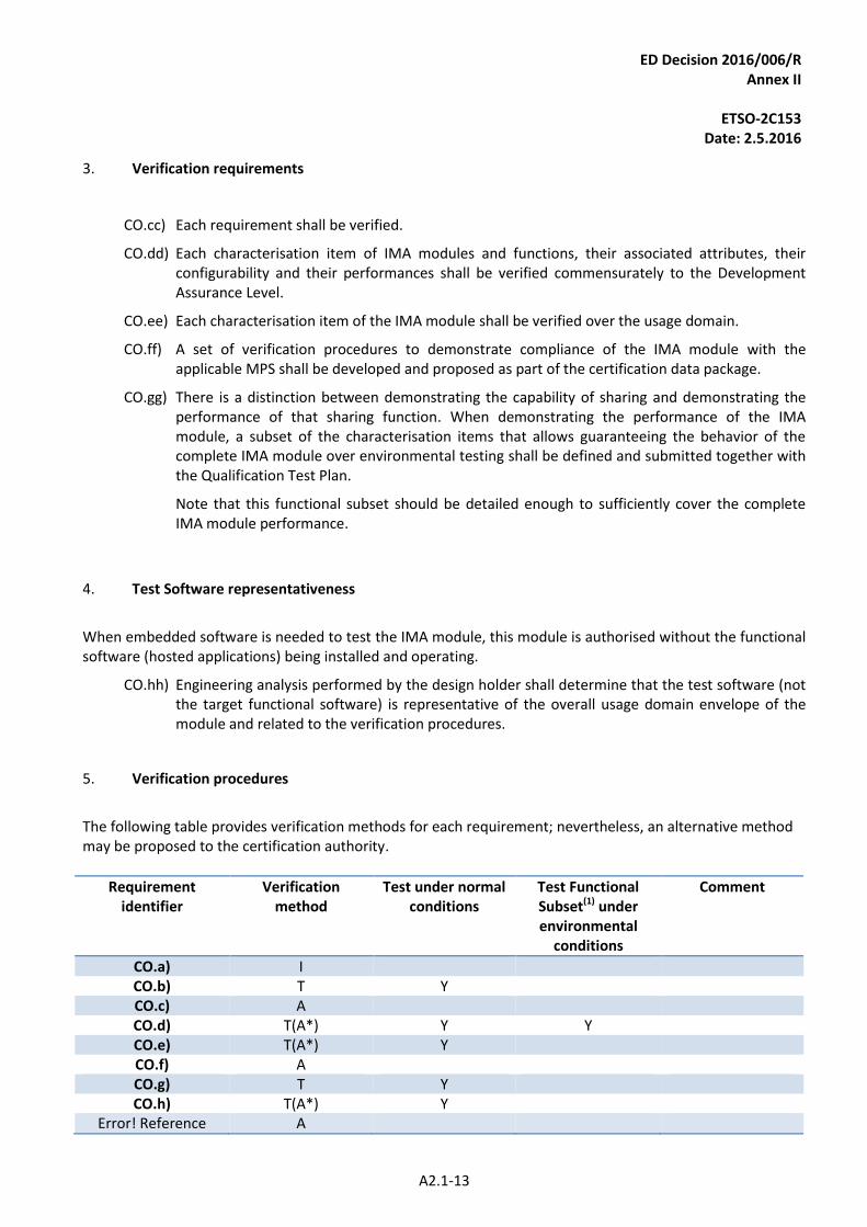
3. Verification requirements
CO.cc) Each requirement shall be verified.
CO.dd) Each characterisation item of IMA modules and functions, their associated attributes, their configurability and their performances shall be verified commensurately to the Development Assurance Level.
CO.ee) Each characterisation item of the IMA module shall be verified over the usage domain.
CO.ff) A set of verification procedures to demonstrate compliance of the IMA module with the applicable MPS shall be developed and proposed as part of the certification data package.
CO.gg) There is a distinction between demonstrating the capability of sharing and demonstrating the performance of that sharing function. When demonstrating the performance of the IMA module, a subset of the characterisation items that allows guaranteeing the behavior of the complete IMA module over environmental testing shall be defined and submitted together with the Qualification Test Plan.
Note that this functional subset should be detailed enough to sufficiently cover the complete IMA module performance.
4. Test Software representativeness
When embedded software is needed to test the IMA module, this module is authorised without the functional software (hosted applications) being installed and operating.
CO.hh) Engineering analysis performed by the design holder shall determine that the test software (not the target functional software) is representative of the overall usage domain envelope of the module and related to the verification procedures.
5. Verification procedures
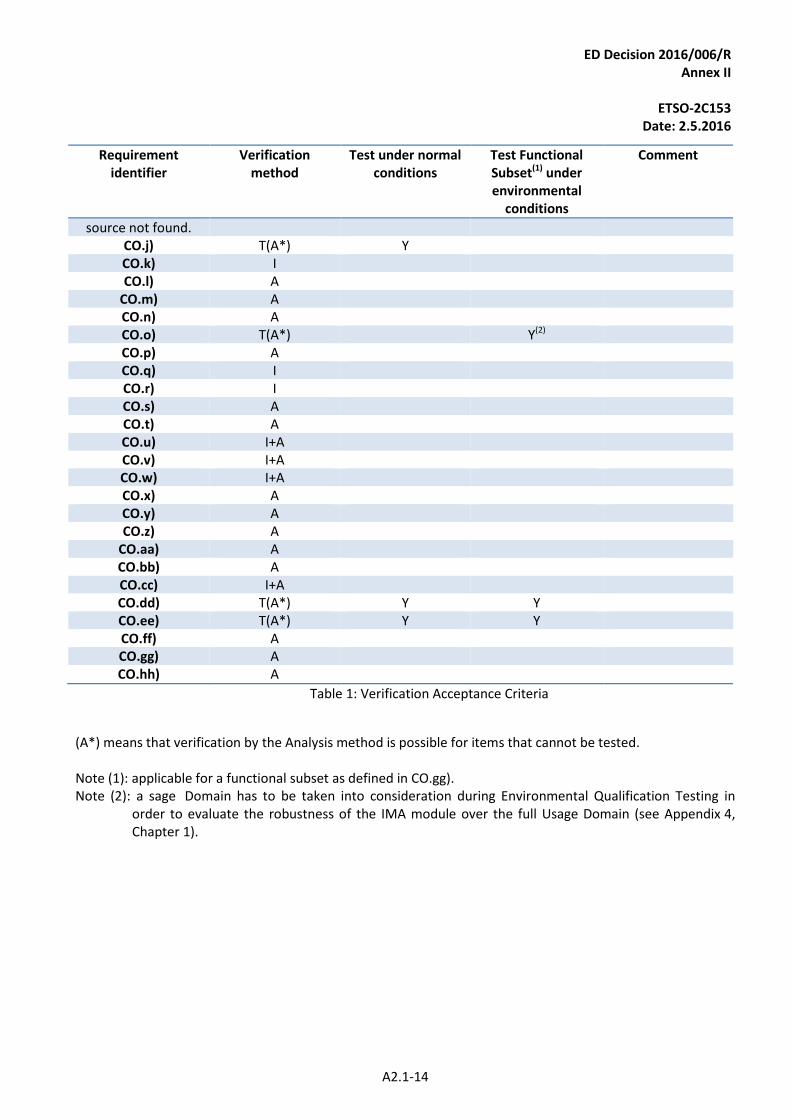
The following table provides verification methods for each requirement; nevertheless, an alternative method may be proposed to the certification authority.
Requirement identifier
Verification method
Test under normal conditions
Test Functional Subset(1) under environmental
conditions
Comment
CO.a) I CO.b) T Y CO.c) A CO.d) T(A*) Y Y CO.e) T(A*) Y CO.f) A CO.g) T Y CO.h) T(A*) Y
Error! Reference A
ED Decision 2016/006/R Annex II
ETSO-2C153
Date: 2.5.2016
A2.1-14
Requirement identifier
Verification method
Test under normal conditions
Test Functional Subset(1) under environmental
conditions
Comment
source not found. CO.j) T(A*) Y CO.k) I CO.l) A
CO.m) A CO.n) A CO.o) T(A*) Y(2) CO.p) A CO.q) I CO.r) I CO.s) A CO.t) A CO.u) I+A CO.v) I+A CO.w) I+A CO.x) A CO.y) A CO.z) A
CO.aa) A CO.bb) A CO.cc) I+A CO.dd) T(A*) Y Y CO.ee) T(A*) Y Y CO.ff) A CO.gg) A CO.hh) A
Table 1: Verification Acceptance Criteria
(A*) means that verification by the Analysis method is possible for items that cannot be tested. Note (1): applicable for a functional subset as defined in CO.gg). Note (2): a sage Domain has to be taken into consideration during Environmental Qualification Testing in
order to evaluate the robustness of the IMA module over the full Usage Domain (see Appendix 4, Chapter 1).
ED Decision 2016/006/R Annex II
ETSO-2C153
Date: 2.5.2016
A2.2-1
APPENDIX 2.2
INTEGRATED MODULAR AVIONICS (IMA) PLATFORM AND MODULE
MINIMUM PERFORMANCE SPECIFICATION (MPS)
CLASS RH: Rack Housing
1. Purpose and scope
Introduction 1.1.
This Appendix contains Minimum Performance Standards (MPS) for CLASS RH Intended Function: Rack Housing. These standards specify module characteristics that should be useful to designers, manufacturers, installers and users of the IMA module.
Definitions 1.2.
For ETSO-2C153 CLASS RH, the IMA module is a physical package able to contain at least two hardware modules, which may provide partial protection from environmental effects (shielding, etc.) and enable installation and removal of those module(s) from the aircraft without physically altering other aircraft systems or equipment. These IMA modules may be simple mechanical enclosures, or they may incorporate passive communication interfaces, a passive interconnection of data and power, an active or passive cooling unit or any combination of these features. Following definitions are used:
— ‘Mounted’ refers to another hardware module, installed and fixed inside the IMA Rack Module, after a human operation.
— ‘Slot’ is a physical space inside the Rack Module, allocated to one hardware module. These definitions are independent of the design choices made by the IMA module manufacturer. Note:
— The IMA module compliant to ETSO-2C153 CLASS RH MPS is only relevant in case of an IMA platform architecture using a Cabinet; and
— hardware modules mounted inside the Rack Housing will be themselves IMA modules (compliant with ETSO-2C153 MPS classes other than RH) or non-IMA modules (i.e. non-IMA application specific hardware).
ED Decision 2016/006/R Annex II
ETSO-2C153
Date: 2.5.2016
A2.2-2
2C153
Authorised
2C153
Authorised
Rack
(CLASS RH)
Power Supply
(CLASS PS)
2C153
Authorised
Data Storage
(CLASS DS)
2C153
Authorised
Processing
(CLASS PR)
PO
WE
R S
UP
PL
Y
MO
DU
LE
PR
OC
ES
SIN
G
MO
DU
LE
GN
SS
M
OD
UL
E
I/O
M
OD
UL
E
DA
TA
S
TO
RA
GE
MO
DU
LE
2C153
Authorised
Interface
(CLASS IF)
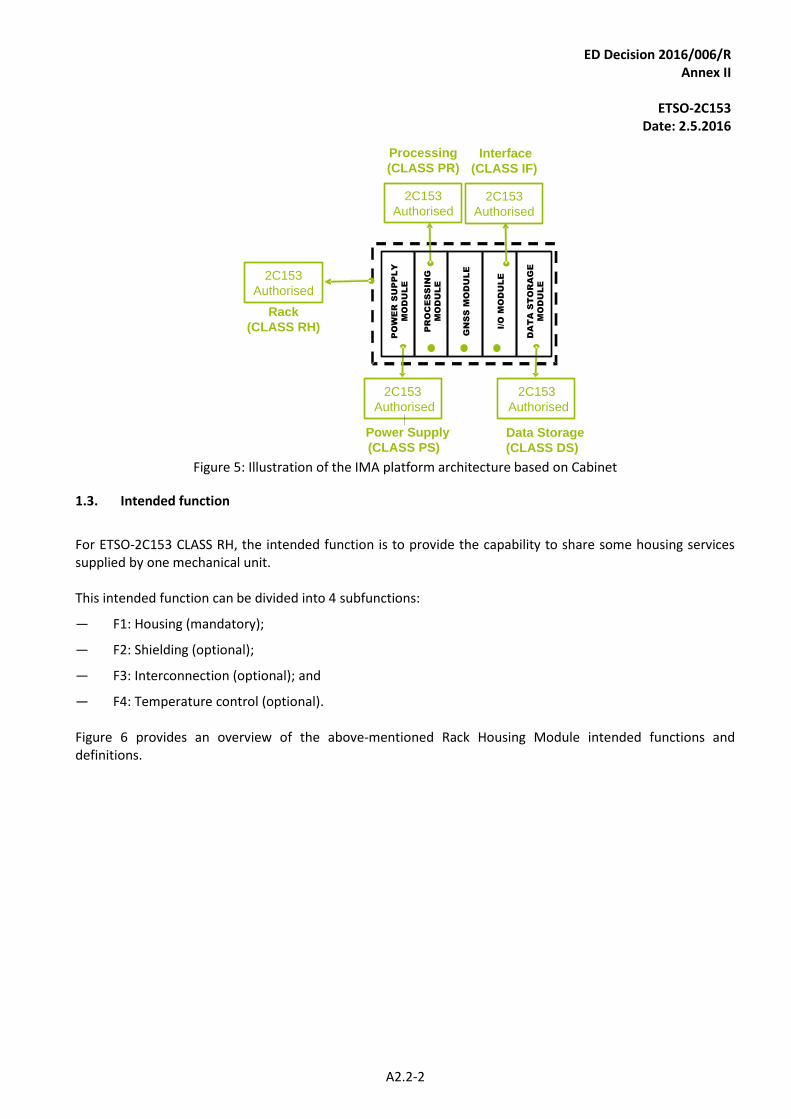
Figure 5: Illustration of the IMA platform architecture based on Cabinet
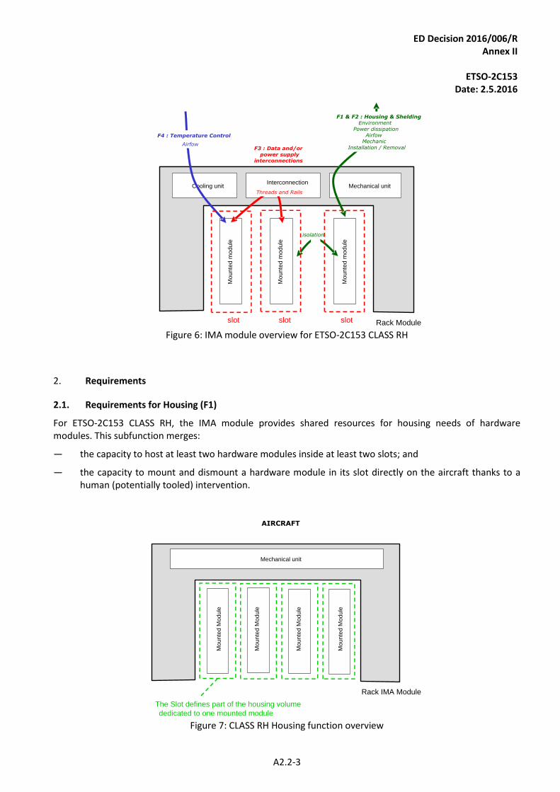
Intended function 1.3.
For ETSO-2C153 CLASS RH, the intended function is to provide the capability to share some housing services supplied by one mechanical unit. This intended function can be divided into 4 subfunctions:
— F1: Housing (mandatory);
— F2: Shielding (optional);
— F3: Interconnection (optional); and
— F4: Temperature control (optional). Figure 6 provides an overview of the above-mentioned Rack Housing Module intended functions and definitions.
ED Decision 2016/006/R Annex II
ETSO-2C153
Date: 2.5.2016
A2.2-3
Rack Module
Cooling unit Mechanical unitInterconnection
F1 & F2 : Housing & SheldingEnvironment
Power dissipationAirfow
MechanicInstallation / RemovalF3 : Data and/or
power supply interconnections
Threads and Rails
Airfow
F4 : Temperature Control
isolation
slot slot slot
Mo
un
ted
mo
du
le
Mo
un
ted
mo
du
le
Mo
un
ted
mo
du
le
Figure 6: IMA module overview for ETSO-2C153 CLASS RH
2. Requirements
Requirements for Housing (F1) 2.1.
For ETSO-2C153 CLASS RH, the IMA module provides shared resources for housing needs of hardware modules. This subfunction merges:
— the capacity to host at least two hardware modules inside at least two slots; and
— the capacity to mount and dismount a hardware module in its slot directly on the aircraft thanks to a human (potentially tooled) intervention.
Rack IMA Module
Mo
un
ted
Mo
du
le
Mechanical unit
AIRCRAFT
The Slot defines part of the housing volume
dedicated to one mounted module
Mo
un
ted
Mo
du
le
Mo
un
ted
Mo
du
le
Mo
un
ted
Mo
du
le
Figure 7: CLASS RH Housing function overview
ED Decision 2016/006/R Annex II
ETSO-2C153
Date: 2.5.2016
A2.2-4
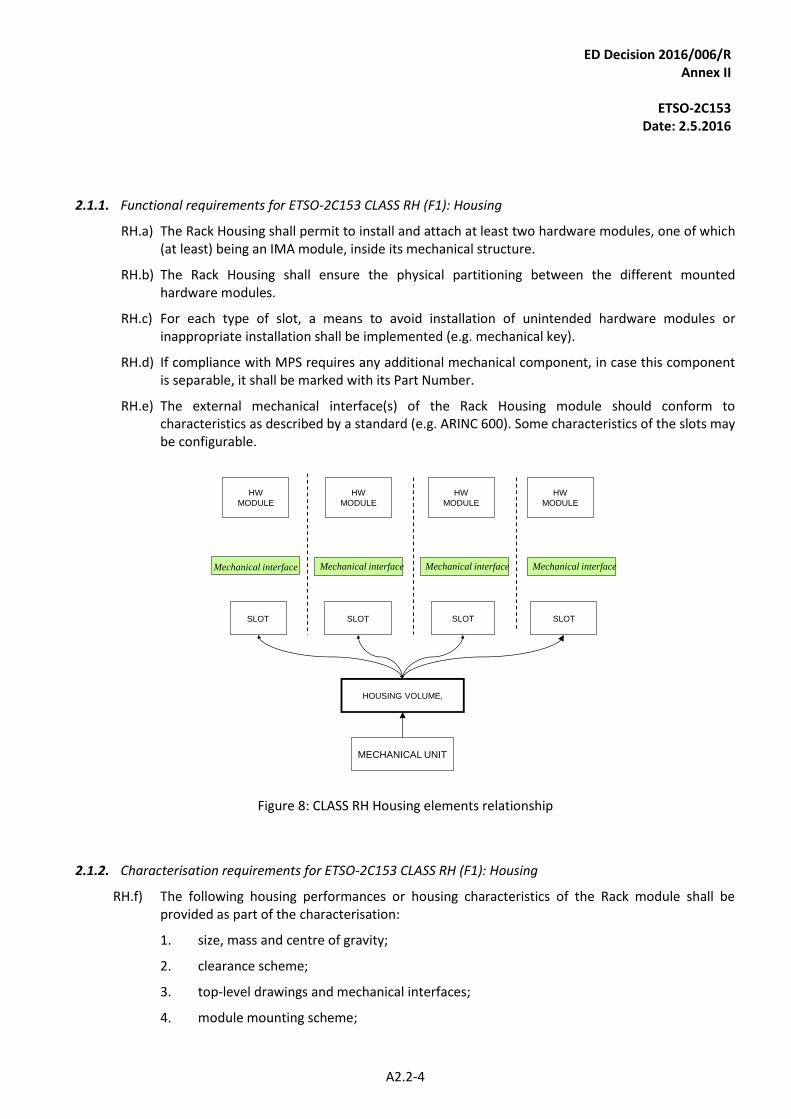
2.1.1. Functional requirements for ETSO-2C153 CLASS RH (F1): Housing
RH.a) The Rack Housing shall permit to install and attach at least two hardware modules, one of which (at least) being an IMA module, inside its mechanical structure.
RH.b) The Rack Housing shall ensure the physical partitioning between the different mounted hardware modules.
RH.c) For each type of slot, a means to avoid installation of unintended hardware modules or inappropriate installation shall be implemented (e.g. mechanical key).
RH.d) If compliance with MPS requires any additional mechanical component, in case this component is separable, it shall be marked with its Part Number.
RH.e) The external mechanical interface(s) of the Rack Housing module should conform to characteristics as described by a standard (e.g. ARINC 600). Some characteristics of the slots may be configurable.
MECHANICAL UNIT
HOUSING VOLUME,
SLOT SLOTSLOT SLOT
HW
MODULE
HW
MODULE
HW
MODULE
HW
MODULE
Mechanical interface Mechanical interface Mechanical interface Mechanical interface
Figure 8: CLASS RH Housing elements relationship
2.1.2. Characterisation requirements for ETSO-2C153 CLASS RH (F1): Housing
RH.f) The following housing performances or housing characteristics of the Rack module shall be provided as part of the characterisation:
1. size, mass and centre of gravity;
2. clearance scheme;
3. top-level drawings and mechanical interfaces;
4. module mounting scheme;
ED Decision 2016/006/R Annex II
ETSO-2C153
Date: 2.5.2016
A2.2-5
5. installation and extraction mechanisms;
6. temperature control (e.g. airflow, cooling, etc.) performances if function is implemented;
7. lists of slots and associated performances (physical scheme, temperature profile, connector, etc.).
Note: these characterisation requirements are additional to those applicable in Appendix 2.1 — COMMON).
RH.g) The characterisation shall include the description of the mounted hardware module installation and extraction means and methods.
RH.h) The characterisation shall provide the list of types of slots, their associated attributes, their configurability (if any) and their sizing dimensions (drawings).
This characterisation shall include:
1. the list of authorised or predefined hardware modules (if any);
2. the list of minimum requirements that a hardware module shall comply with for its capacity to be inserted into the rack;
3. slot mounting scheme (mechanical profile/drawings) and characteristics (torque, maximum number of insertions, etc.); and
4. power dissipation and airflow profile.
RH.i) The characterisation, including the usage domain, shall be sufficiently accurate to permit specification and validation of the expected performance of the mounted hardware module.
RH.j) The characterisation shall include configuration, weight and geometric data that are needed to evaluate mass and centre of gravity of a populated and partly populated rack.
RH.k) The characterisation shall include the installation instructions of the additional mechanical component that is necessary for being compliant with MPS.
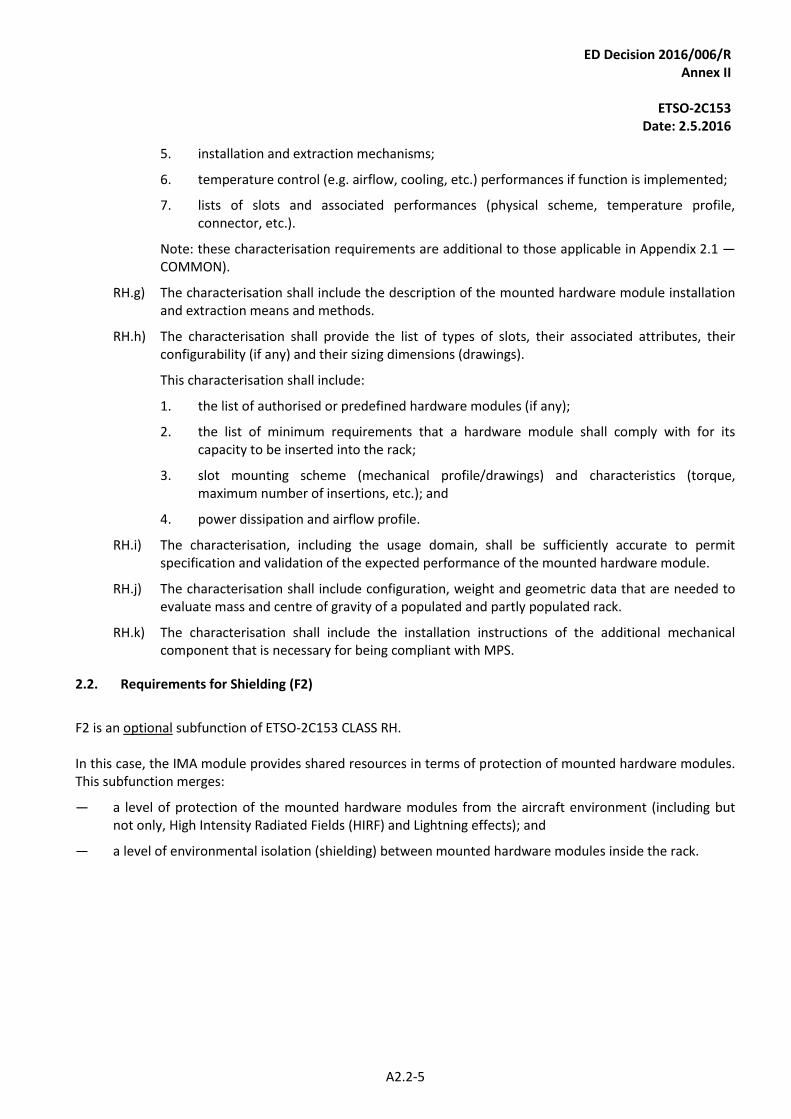
Requirements for Shielding (F2) 2.2.
F2 is an optional subfunction of ETSO-2C153 CLASS RH. In this case, the IMA module provides shared resources in terms of protection of mounted hardware modules. This subfunction merges:
— a level of protection of the mounted hardware modules from the aircraft environment (including but not only, High Intensity Radiated Fields (HIRF) and Lightning effects); and
— a level of environmental isolation (shielding) between mounted hardware modules inside the rack.
ED Decision 2016/006/R Annex II
ETSO-2C153
Date: 2.5.2016
A2.2-6
Rack IMA Module
Mechanical unit
Mo
un
ted
Mo
du
le
AIRCRAFT ENVIRONMENT
Environmental isolation
Mo
un
ted
Mo
du
le
Mo
un
ted
Mo
du
le
Mo
un
ted
Mo
du
le
Figure 9: CLASS RH Shielding function overview
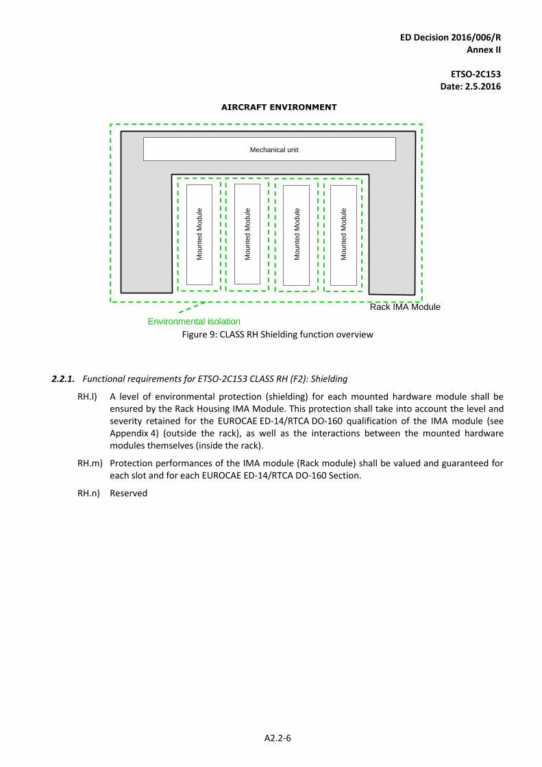
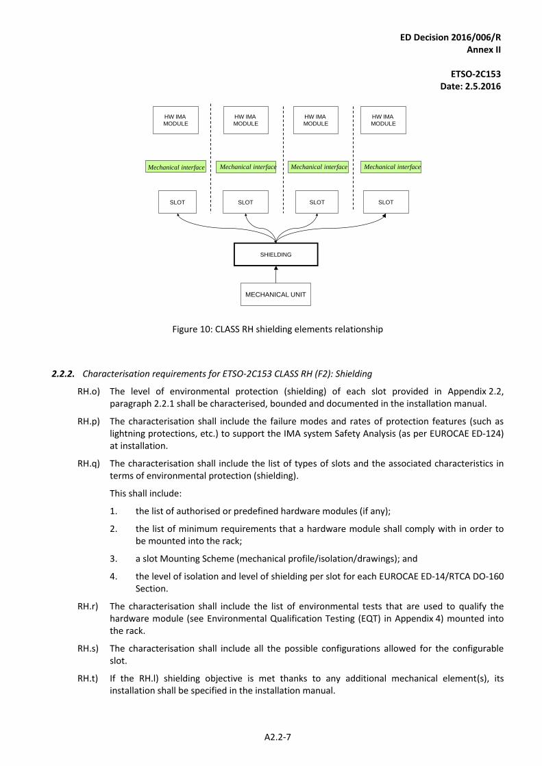
2.2.1. Functional requirements for ETSO-2C153 CLASS RH (F2): Shielding
RH.l) A level of environmental protection (shielding) for each mounted hardware module shall be ensured by the Rack Housing IMA Module. This protection shall take into account the level and severity retained for the EUROCAE ED-14/RTCA DO-160 qualification of the IMA module (see Appendix 4) (outside the rack), as well as the interactions between the mounted hardware modules themselves (inside the rack).
RH.m) Protection performances of the IMA module (Rack module) shall be valued and guaranteed for each slot and for each EUROCAE ED-14/RTCA DO-160 Section.
RH.n) Reserved
ED Decision 2016/006/R Annex II
ETSO-2C153
Date: 2.5.2016
A2.2-7
MECHANICAL UNIT
SHIELDING
SLOT SLOTSLOT SLOT
HW IMA
MODULE
HW IMA
MODULE
HW IMA
MODULE
HW IMA
MODULE
Mechanical interface Mechanical interface Mechanical interface Mechanical interface
Figure 10: CLASS RH shielding elements relationship
2.2.2. Characterisation requirements for ETSO-2C153 CLASS RH (F2): Shielding
RH.o) The level of environmental protection (shielding) of each slot provided in Appendix 2.2, paragraph 2.2.1 shall be characterised, bounded and documented in the installation manual.
RH.p) The characterisation shall include the failure modes and rates of protection features (such as lightning protections, etc.) to support the IMA system Safety Analysis (as per EUROCAE ED-124) at installation.
RH.q) The characterisation shall include the list of types of slots and the associated characteristics in terms of environmental protection (shielding).
This shall include:
1. the list of authorised or predefined hardware modules (if any);
2. the list of minimum requirements that a hardware module shall comply with in order to be mounted into the rack;
3. a slot Mounting Scheme (mechanical profile/isolation/drawings); and
4. the level of isolation and level of shielding per slot for each EUROCAE ED-14/RTCA DO-160 Section.
RH.r) The characterisation shall include the list of environmental tests that are used to qualify the hardware module (see Environmental Qualification Testing (EQT) in Appendix 4) mounted into the rack.
RH.s) The characterisation shall include all the possible configurations allowed for the configurable slot.
RH.t) If the RH.l) shielding objective is met thanks to any additional mechanical element(s), its installation shall be specified in the installation manual.
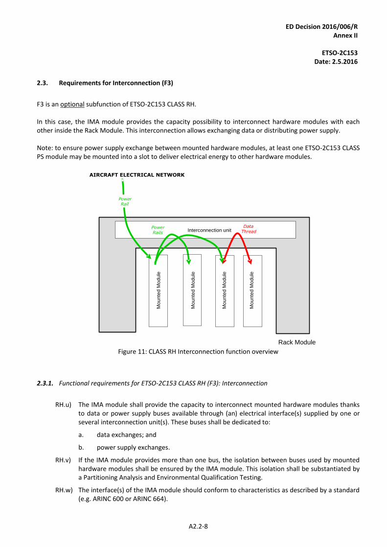
ED Decision 2016/006/R Annex II
ETSO-2C153
Date: 2.5.2016
A2.2-8
Requirements for Interconnection (F3) 2.3.
F3 is an optional subfunction of ETSO-2C153 CLASS RH. In this case, the IMA module provides the capacity possibility to interconnect hardware modules with each other inside the Rack Module. This interconnection allows exchanging data or distributing power supply. Note: to ensure power supply exchange between mounted hardware modules, at least one ETSO-2C153 CLASS PS module may be mounted into a slot to deliver electrical energy to other hardware modules.
Rack Module
Mo
un
ted
Mo
du
le
TYPE F Interconnection unitData
ThreadPowerRails
AIRCRAFT ELECTRICAL NETWORK
PowerRail
Mo
un
ted
Mo
du
le
Mo
un
ted
Mo
du
le
Mo
un
ted
Mo
du
le
Figure 11: CLASS RH Interconnection function overview
2.3.1. Functional requirements for ETSO-2C153 CLASS RH (F3): Interconnection
RH.u) The IMA module shall provide the capacity to interconnect mounted hardware modules thanks
to data or power supply buses available through (an) electrical interface(s) supplied by one or several interconnection unit(s). These buses shall be dedicated to:
a. data exchanges; and
b. power supply exchanges.
RH.v) If the IMA module provides more than one bus, the isolation between buses used by mounted hardware modules shall be ensured by the IMA module. This isolation shall be substantiated by a Partitioning Analysis and Environmental Qualification Testing.
RH.w) The interface(s) of the IMA module should conform to characteristics as described by a standard (e.g. ARINC 600 or ARINC 664).
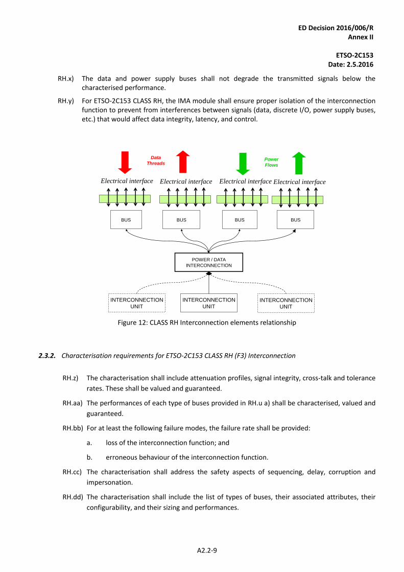
ED Decision 2016/006/R Annex II
ETSO-2C153
Date: 2.5.2016
A2.2-9
RH.x) The data and power supply buses shall not degrade the transmitted signals below the characterised performance.
RH.y) For ETSO-2C153 CLASS RH, the IMA module shall ensure proper isolation of the interconnection function to prevent from interferences between signals (data, discrete I/O, power supply buses, etc.) that would affect data integrity, latency, and control.
INTERCONNECTION
UNIT
POWER / DATA
INTERCONNECTION
BUS BUSBUS BUS
INTERCONNECTION
UNITINTERCONNECTION
UNIT
Electrical interface Electrical interface Electrical interface Electrical interface
Power
Flows
Data
Threads
Figure 12: CLASS RH Interconnection elements relationship
2.3.2. Characterisation requirements for ETSO-2C153 CLASS RH (F3) Interconnection
RH.z) The characterisation shall include attenuation profiles, signal integrity, cross-talk and tolerance
rates. These shall be valued and guaranteed.
RH.aa) The performances of each type of buses provided in RH.u a) shall be characterised, valued and
guaranteed.
RH.bb) For at least the following failure modes, the failure rate shall be provided:
a. loss of the interconnection function; and
b. erroneous behaviour of the interconnection function.
RH.cc) The characterisation shall address the safety aspects of sequencing, delay, corruption and
impersonation.
RH.dd) The characterisation shall include the list of types of buses, their associated attributes, their
configurability, and their sizing and performances.
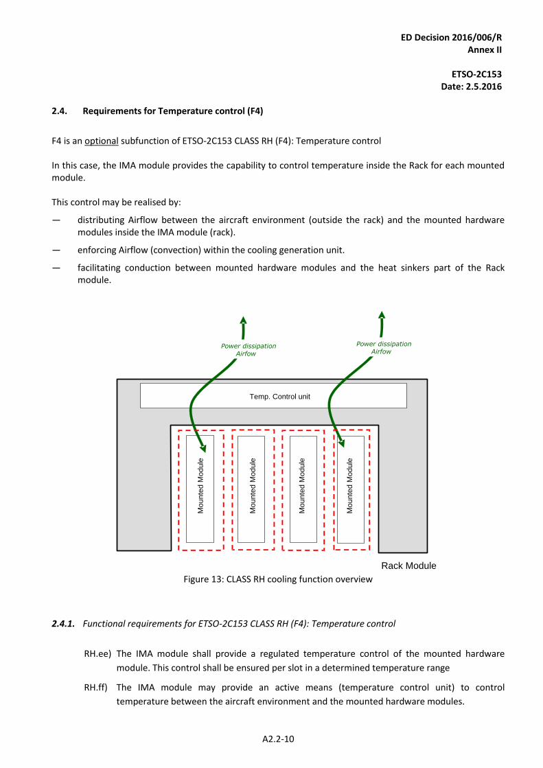
ED Decision 2016/006/R Annex II
ETSO-2C153
Date: 2.5.2016
A2.2-10
Requirements for Temperature control (F4) 2.4.
F4 is an optional subfunction of ETSO-2C153 CLASS RH (F4): Temperature control In this case, the IMA module provides the capability to control temperature inside the Rack for each mounted module. This control may be realised by:
— distributing Airflow between the aircraft environment (outside the rack) and the mounted hardware modules inside the IMA module (rack).
— enforcing Airflow (convection) within the cooling generation unit.
— facilitating conduction between mounted hardware modules and the heat sinkers part of the Rack module.
Rack Module
Mo
un
ted
Mo
du
le
Temp. Control unit
Power dissipationAirfow
Power dissipationAirfow
Mo
un
ted
Mo
du
le
Mo
un
ted
Mo
du
le
Mo
un
ted
Mo
du
le
Figure 13: CLASS RH cooling function overview
2.4.1. Functional requirements for ETSO-2C153 CLASS RH (F4): Temperature control
RH.ee) The IMA module shall provide a regulated temperature control of the mounted hardware
module. This control shall be ensured per slot in a determined temperature range
RH.ff) The IMA module may provide an active means (temperature control unit) to control
temperature between the aircraft environment and the mounted hardware modules.
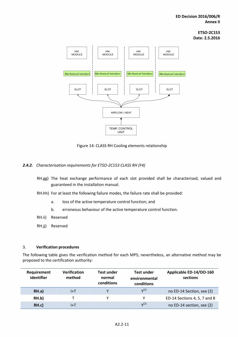
ED Decision 2016/006/R Annex II
ETSO-2C153
Date: 2.5.2016
A2.2-11
TEMP. CONTROL
UNIT
AIRFLOW / HEAT
SLOT SLOTSLOT SLOT
HW
MODULE
HW
MODULE
HW
MODULE
HW
MODULE
Mechanical interface Mechanical interface Mechanical interface Mechanical interface
Figure 14: CLASS RH Cooling elements relationship
2.4.2. Characterisation requirements for ETSO-2C153 CLASS RH (F4)
RH.gg) The heat exchange performance of each slot provided shall be characterised, valued and
guaranteed in the installation manual.
RH.hh) For at least the following failure modes, the failure rate shall be provided:
a. loss of the active temperature control function; and
b. erroneous behaviour of the active temperature control function.
RH.ii) Reserved
RH.jj) Reserved
3. Verification procedures
The following table gives the verification method for each MPS; nevertheless, an alternative method may be proposed to the certification authority:
Requirement identifier
Verification method
Test under normal
conditions
Test under
environmental conditions
Applicable ED-14/DO-160 sections
RH.a) I+T Y Y(2) no ED-14 Section, see (2)
RH.b) T Y Y ED-14 Sections 4, 5, 7 and 8
RH.c) I+T Y(2) no ED-14 section, see (2)
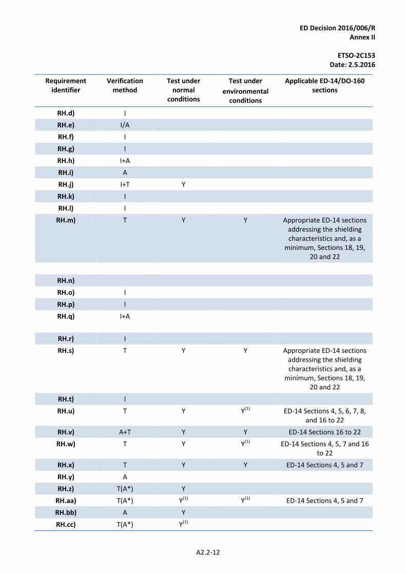
ED Decision 2016/006/R Annex II
ETSO-2C153
Date: 2.5.2016
A2.2-12
Requirement identifier
Verification method
Test under normal
conditions
Test under
environmental conditions
Applicable ED-14/DO-160 sections
RH.d) I
RH.e) I/A
RH.f) I
RH.g) I
RH.h) I+A
RH.i) A
RH.j) I+T Y
RH.k) I
RH.l) I
RH.m) T Y Y Appropriate ED-14 sections addressing the shielding characteristics and, as a
minimum, Sections 18, 19, 20 and 22
RH.n)
RH.o) I
RH.p) I
RH.q) I+A
RH.r) I
RH.s) T Y Y Appropriate ED-14 sections addressing the shielding characteristics and, as a
minimum, Sections 18, 19, 20 and 22
RH.t) I
RH.u) T Y Y(1) ED-14 Sections 4, 5, 6, 7, 8, and 16 to 22
RH.v) A+T Y Y ED-14 Sections 16 to 22
RH.w) T Y Y(1) ED-14 Sections 4, 5, 7 and 16 to 22
RH.x) T Y Y ED-14 Sections 4, 5 and 7
RH.y) A
RH.z) T(A*) Y
RH.aa) T(A*) Y(1) Y(1) ED-14 Sections 4, 5 and 7
RH.bb) A Y
RH.cc) T(A*) Y(1)
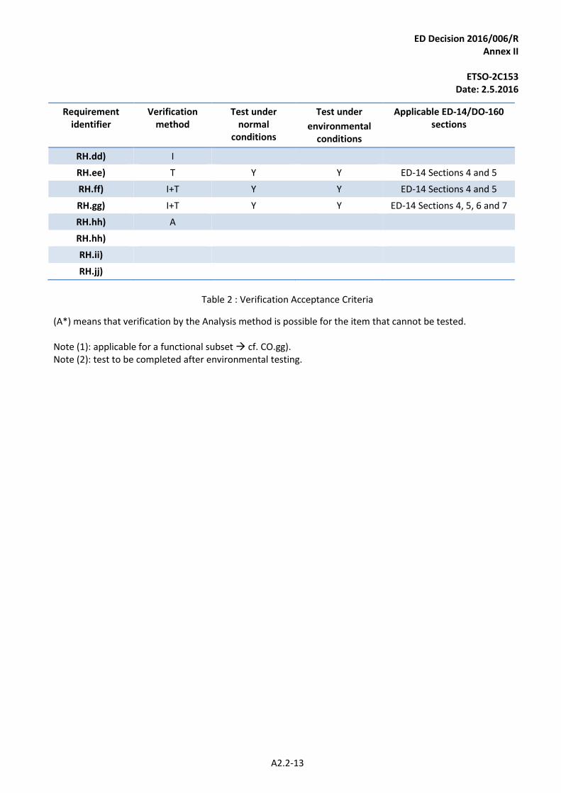
ED Decision 2016/006/R Annex II
ETSO-2C153
Date: 2.5.2016
A2.2-13
Requirement identifier
Verification method
Test under normal
conditions
Test under
environmental conditions
Applicable ED-14/DO-160 sections
RH.dd) I
RH.ee) T Y Y ED-14 Sections 4 and 5
RH.ff) I+T Y Y ED-14 Sections 4 and 5
RH.gg) I+T Y Y ED-14 Sections 4, 5, 6 and 7
RH.hh) A
RH.hh)
RH.ii)
RH.jj)
Table 2 : Verification Acceptance Criteria
(A*) means that verification by the Analysis method is possible for the item that cannot be tested. Note (1): applicable for a functional subset cf. CO.gg). Note (2): test to be completed after environmental testing.
ED Decision 2016/006/R Annex II
ETSO-2C153
Date: 2.5.2016
A2.3-1
APPENDIX 2.3
INTEGRATED MODULAR AVIONICS (IMA) PLATFORM AND MODULE
MINIMUM PERFORMANCE SPECIFICATION (MPS)
CLASS PR: Processing
1. Purpose and scope
1.1. Introduction
This Appendix contains Minimum Performance Standards (MPSs) for CLASS PR Intended Function: Processing (PR). These standards specify characteristics that should be useful to designers, manufacturers, installers and users of the IMA module.
1.2. Definitions
For ETSO-2C153 CLASS PR, the IMA module provides shared resources in terms of processing between hosted applications, modules and/or components. The following definitions are used:
— Processing Unit: a set of physical components (hardware and/or software) in charge of carrying out the instructions of a computer programme by performing the basic arithmetical, logical, and input/output operations of the Executable Object Code.
— Executable Object Code (EUROCAE ED-12C/RTCA DO-178C): a form of code that is directly usable by the processing unit of the target computer and is, therefore, a compiled, assembled, and linked binary image, loaded into the target computing hardware.
— Processing Element: a well-defined set of instructions which is a primary form of an Executable Object Code execution and for which a level of isolation would be guaranteed by the IMA module.
In the context of PR class, the ‘concurrent item’ defined in Appendix 2.1, paragraph 1 means ‘Processing Element’.
1.3. Intended Function
For ETSO-2C153 CLASS PR, the intended function is to provide the capability to share processing supplied by one or several processing unit(s). The IMA module may include data storage and interfaces between hosted applications, modules and/or components; in this case, this class shall be combined with DS and IF Classes.
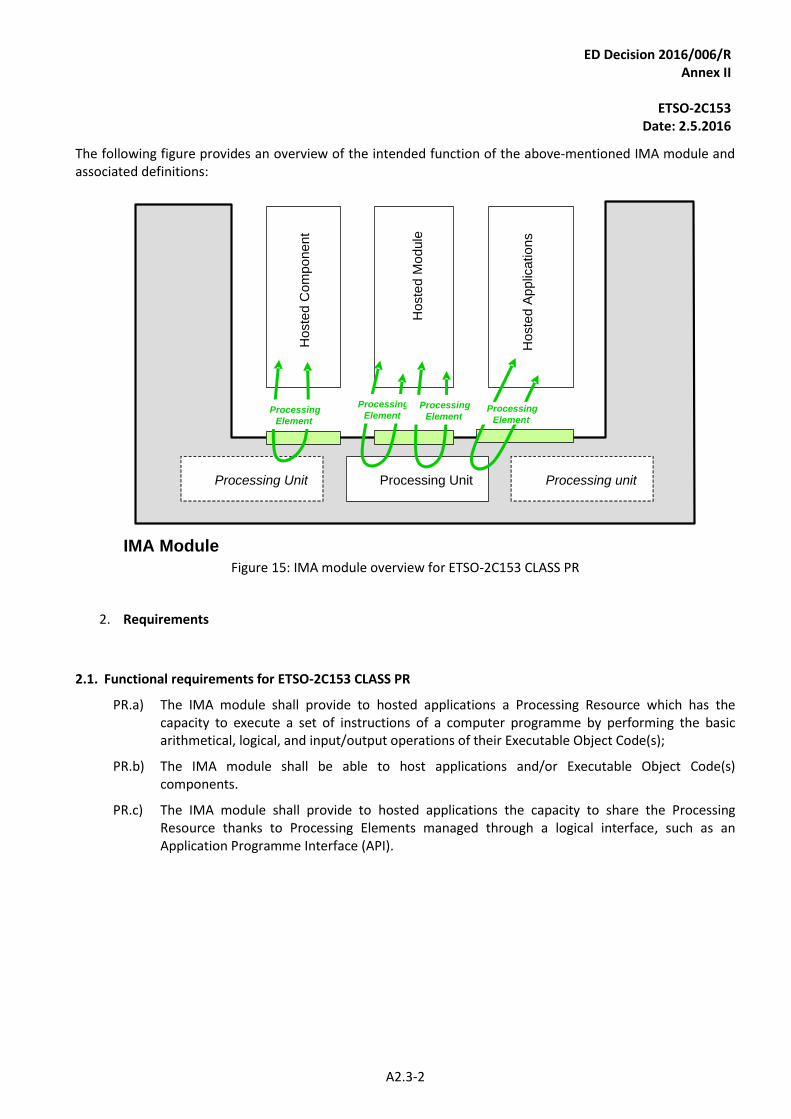
ED Decision 2016/006/R Annex II
ETSO-2C153
Date: 2.5.2016
A2.3-2
The following figure provides an overview of the intended function of the above-mentioned IMA module and associated definitions:
IMA Module
Processing unit
Ho
ste
d C
om
po
ne
nt
Ho
ste
d A
pp
lica
tio
ns
Ho
ste
d M
od
ule
Processing UnitProcessing Unit
Processing
ElementProcessing
ElementProcessing
Element
Processing
Element
Figure 15: IMA module overview for ETSO-2C153 CLASS PR
2. Requirements
2.1. Functional requirements for ETSO-2C153 CLASS PR
PR.a) The IMA module shall provide to hosted applications a Processing Resource which has the capacity to execute a set of instructions of a computer programme by performing the basic arithmetical, logical, and input/output operations of their Executable Object Code(s);
PR.b) The IMA module shall be able to host applications and/or Executable Object Code(s) components.
PR.c) The IMA module shall provide to hosted applications the capacity to share the Processing Resource thanks to Processing Elements managed through a logical interface, such as an Application Programme Interface (API).
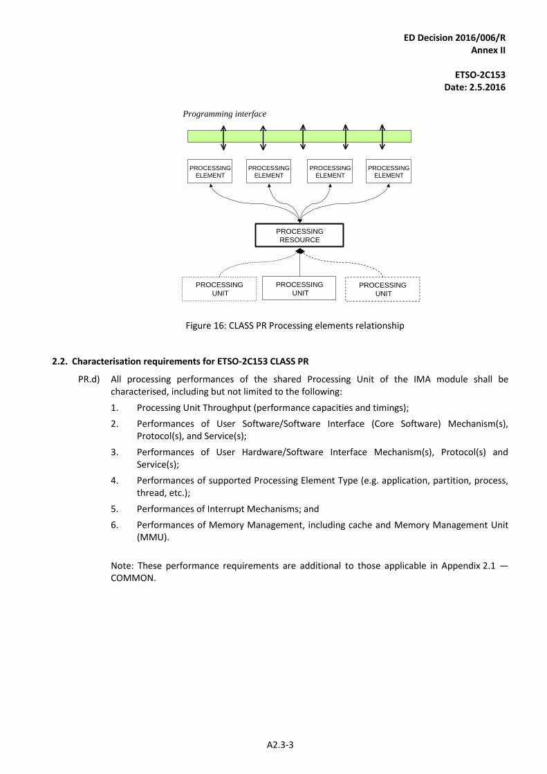
ED Decision 2016/006/R Annex II
ETSO-2C153
Date: 2.5.2016
A2.3-3
PROCESSING
UNIT
PROCESSING
UNITPROCESSING
UNIT
PROCESSING
RESOURCE
PROCESSING
ELEMENT
PROCESSING
ELEMENT
PROCESSING
ELEMENT
PROCESSING
ELEMENT
Programming interface
Figure 16: CLASS PR Processing elements relationship
2.2. Characterisation requirements for ETSO-2C153 CLASS PR
PR.d) All processing performances of the shared Processing Unit of the IMA module shall be characterised, including but not limited to the following:
1. Processing Unit Throughput (performance capacities and timings);
2. Performances of User Software/Software Interface (Core Software) Mechanism(s), Protocol(s), and Service(s);
3. Performances of User Hardware/Software Interface Mechanism(s), Protocol(s) and Service(s);
4. Performances of supported Processing Element Type (e.g. application, partition, process, thread, etc.);
5. Performances of Interrupt Mechanisms; and
6. Performances of Memory Management, including cache and Memory Management Unit (MMU).
Note: These performance requirements are additional to those applicable in Appendix 2.1 — COMMON.
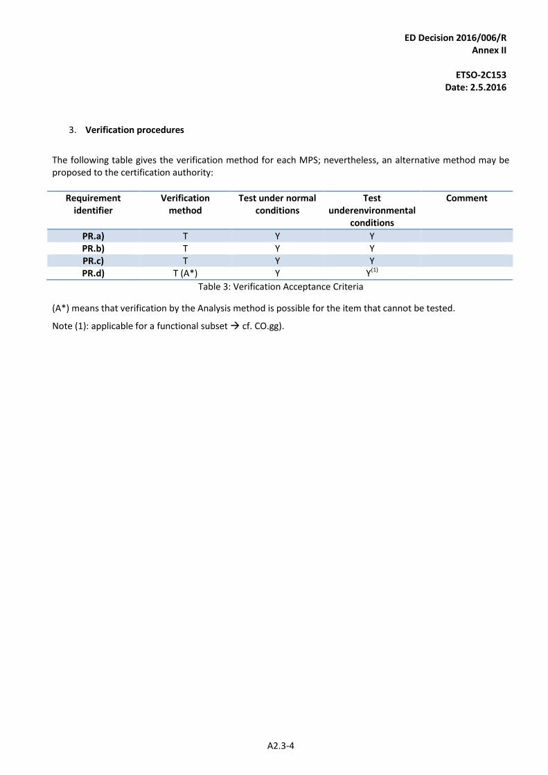
ED Decision 2016/006/R Annex II
ETSO-2C153
Date: 2.5.2016
A2.3-4
3. Verification procedures
The following table gives the verification method for each MPS; nevertheless, an alternative method may be proposed to the certification authority:
Requirement identifier
Verification method
Test under normal conditions
Test underenvironmental
conditions
Comment
PR.a) T Y Y PR.b) T Y Y PR.c) T Y Y PR.d) T (A*) Y Y(1)
Table 3: Verification Acceptance Criteria
(A*) means that verification by the Analysis method is possible for the item that cannot be tested.
Note (1): applicable for a functional subset cf. CO.gg).
ED Decision 2016/006/R Annex II
ETSO-2C153
Date: 2.5.2016
A2.4-1
APPENDIX 2.4
INTEGRATED MODULAR AVIONICS (IMA) MODULE MINIMUM PERFORMANCE SPECIFICATION (MPS)
CLASS GP: Graphical Processing
1. Purpose and scope
Introduction 1.1.
This Appendix contains Minimum Performance Specifications (MPSs) for CLASS GP Intended Function: Graphical Processing. These standards specify characteristics that should be useful to designers, manufacturers, installers and users of the IMA module.
Definitions 1.2.
For ETSO-2C153 CLASS GP, the IMA module provides shared resources in terms of graphical conversion and graphical laying out between hosted applications, modules and/or components based on commands coming from these hosted applications, modules and/or components.
The following definitions are used:
— Graphical Thread: a set of graphical (displayable) information for which a level of isolation would be guaranteed by the IMA module.
— Data Thread: a well-defined set of data which is a primary form of drawing directives received as input by the IMA module from hosted applications, modules and/or components.
— Command Thread: a well-defined set of command directives received as input by the IMA module from hosted applications, modules and/or components in order to change the conversion and laying out settings.
— Graphical conversion: a transformation of a set of data information that is the primary form of drawing directives (data thread) into a set of displayable basic information.
— Laying out: an operation consisting in a combination of merging or/and splitting actions of displayable basic information in order to build the final Graphical Thread to be rendered.
— Conversion Unit: a set of physical components (hardware and/or software) in charge of graphical conversion.
— Laying out Unit: a set of physical components (hardware and/or software) in charge of laying out.
Note:
— both units can be merged in one unit; and
— the final rendering of the graphical thread(s) is out of the scope of this module (refer to CLASS DH).

ED Decision 2016/006/R Annex II
ETSO-2C153
Date: 2.5.2016
A2.4-2
In the context of GP class, the ‘concurrent item’ defined in Appendix 2.1, paragraph 1 means ‘Graphical and/or Command Thread’.
Intended Function 1.3.
For ETSO-2C153 CLASS GP, the intended function is to provide the capability to share graphical conversion and graphical laying out supplied by one or several graphical conversion and graphical laying out unit(s). The function of the Graphical Processing Module is to receive commands from hosted applications, modules and/or components and optionally receive video from external analogue or digital sources to process them and to generate an image to display. This intended function is Graphical Conversion and Laying out resource sharing composed of:
o information acquisition and control;
o information conversion and laying out; and
o information forwarding & control.
The following figure provides an overview of the above-mentioned IMA module intended function and associated definitions:
Class GP: Graphical information ressource sharing
Graphical Conversion Unit(s):
· Applications threads
processing
· External sources
processing
Graphical laying out Unit(s)
(Merge / Split)
L1
L2
L3
L4
Graphical thread = F(data threads)(Cd)
Command threads
L2
L1
L3
L4
Data threads
from
Applications
Command
Threads
From
Applications
One or several
Graphical
Threads
Data threads
from external
sources
Figure 17: IMA module overview for ETSO-2C153 CLASS GP
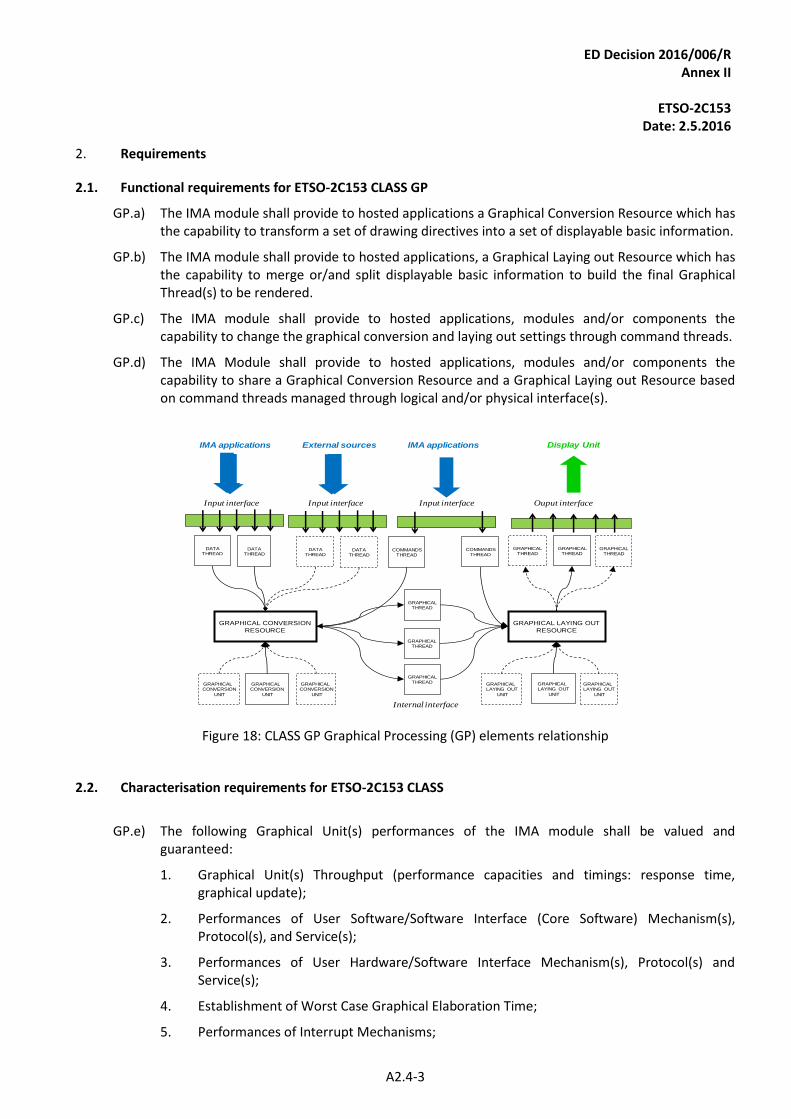
ED Decision 2016/006/R Annex II
ETSO-2C153
Date: 2.5.2016
A2.4-3
2. Requirements
Functional requirements for ETSO-2C153 CLASS GP 2.1.
GP.a) The IMA module shall provide to hosted applications a Graphical Conversion Resource which has the capability to transform a set of drawing directives into a set of displayable basic information.
GP.b) The IMA module shall provide to hosted applications, a Graphical Laying out Resource which has the capability to merge or/and split displayable basic information to build the final Graphical Thread(s) to be rendered.
GP.c) The IMA module shall provide to hosted applications, modules and/or components the capability to change the graphical conversion and laying out settings through command threads.
GP.d) The IMA Module shall provide to hosted applications, modules and/or components the capability to share a Graphical Conversion Resource and a Graphical Laying out Resource based on command threads managed through logical and/or physical interface(s).
GRAPHICAL CONVERSION
UNIT
GRAPHICAL CONVERSION
UNIT
GRAPHICAL CONVERSION
UNIT
GRAPHICAL CONVERSION
RESOURCE
DATATHREAD
DATATHREAD
Input interface
GRAPHICALTHREAD
GRAPHICALTHREAD
GRAPHICALTHREAD
Ouput interface
GRAPHICAL LAYING OUT
UNIT
GRAPHICAL LAYING OUT
UNIT
GRAPHICAL LAYING OUT
UNIT
GRAPHICAL LAYING OUT
RESOURCE
IMA applications
DATATHREAD
DATATHREAD
Internal interface
COMMANDSTHREAD
COMMANDSTHREAD
GRAPHICALTHREAD
GRAPHICALTHREAD
GRAPHICALTHREAD
Input interface Input interface
IMA applications External sources Display Unit
Figure 18: CLASS GP Graphical Processing (GP) elements relationship
Characterisation requirements for ETSO-2C153 CLASS 2.2.
GP.e) The following Graphical Unit(s) performances of the IMA module shall be valued and
guaranteed:
1. Graphical Unit(s) Throughput (performance capacities and timings: response time, graphical update);
2. Performances of User Software/Software Interface (Core Software) Mechanism(s), Protocol(s), and Service(s);
3. Performances of User Hardware/Software Interface Mechanism(s), Protocol(s) and Service(s);
4. Establishment of Worst Case Graphical Elaboration Time;
5. Performances of Interrupt Mechanisms;
ED Decision 2016/006/R Annex II
ETSO-2C153
Date: 2.5.2016
A2.4-4
6. Performances of supported Data Thread types;
7. Performances of supported Graphical Thread types; and
8. Performances of supported Command Thread types.
Note: These performance requirements are additional to those applicable in Appendix 2.1 — COMMON.
GP.f) In addition to Common Requirement CO.w), particular emphasis shall be given to precluding or mitigating failures which could result in hazardously misleading information. Undetected loss of information or frozen information could contribute to hazardously misleading information.
Note: this is applicable to all GP module functionalities including the implementation of image windowing, superimposition etc.
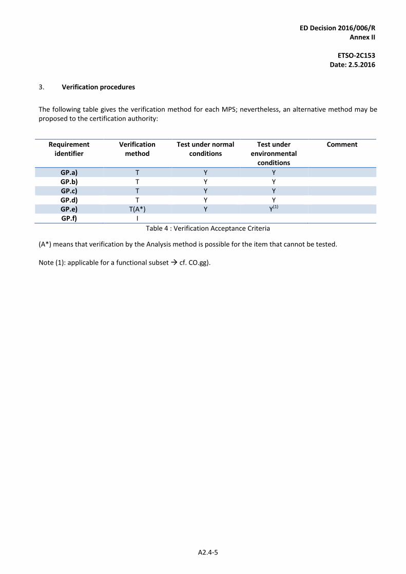
ED Decision 2016/006/R Annex II
ETSO-2C153
Date: 2.5.2016
A2.4-5
3. Verification procedures
The following table gives the verification method for each MPS; nevertheless, an alternative method may be proposed to the certification authority:
Requirement identifier
Verification method
Test under normal conditions
Test under environmental
conditions
Comment
GP.a) T Y Y GP.b) T Y Y GP.c) T Y Y GP.d) T Y Y GP.e) T(A*) Y Y(1) GP.f) I
Table 4 : Verification Acceptance Criteria
(A*) means that verification by the Analysis method is possible for the item that cannot be tested. Note (1): applicable for a functional subset cf. CO.gg).
ED Decision 2016/006/R Annex II
ETSO-2C153
Date: 2.5.2016
A2.5-1
APPENDIX 2.5
INTEGRATED MODULAR AVIONICS (IMA) PLATFORM AND MODULE MINIMUM PERFORMANCE SPECIFICATION (MPS)
CLASS DS: Data Storage (DS)
1. Purpose and scope
Introduction 1.1.
This Appendix contains Minimum Performance Standards (MPSs) for CLASS DS Intended Function: Data Storage. These standards specify characteristics that should be useful to designers, manufacturers, installers and users of the IMA module.
Definitions 1.2.
For ETSO-2C153 CLASS DS, the IMA module provides shared resources in terms of data storage between hosted applications, modules and/or components. Data Storage refers to the storage of data in a continuing and machine-readable mode. A Data Storage module that records data may access both the separate portable (removable) recording component and/or permanent component to store and retrieve data. Following definitions are used:
— Storage Unit: a set of physical components (hardware and/or software) in charge of supplying and managing recorded data resources (e.g. memory components and associated interfaces, etc.)
— Data Storage Element: a completely defined set of data storage which is a primary form of recorded data and for which a level of isolation would be guaranteed by the IMA module.
In the context of DS class, the ‘concurrent item’ defined in Appendix 2.1, paragraph 1 means ‘Data Storage Element’.
Intended Function 1.3.
For ETSO-2C153 CLASS DS, the intended function is to provide the capability to share recorded data or data storage space supplied by one or several storage unit(s).
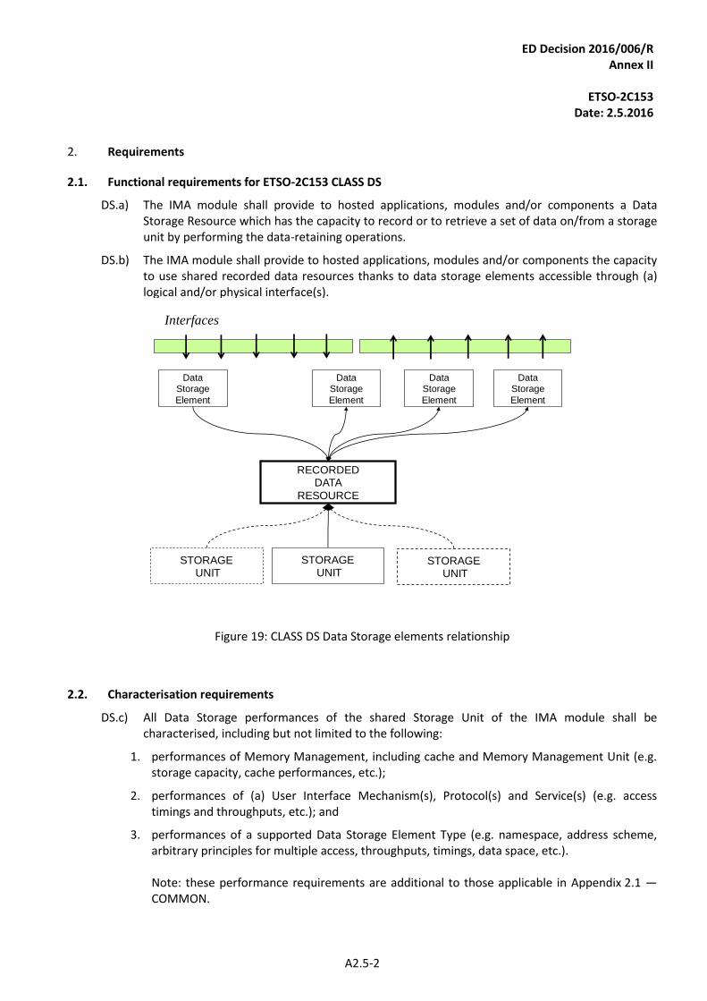
ED Decision 2016/006/R Annex II
ETSO-2C153
Date: 2.5.2016
A2.5-2
2. Requirements
Functional requirements for ETSO-2C153 CLASS DS 2.1.
DS.a) The IMA module shall provide to hosted applications, modules and/or components a Data Storage Resource which has the capacity to record or to retrieve a set of data on/from a storage unit by performing the data-retaining operations.
DS.b) The IMA module shall provide to hosted applications, modules and/or components the capacity to use shared recorded data resources thanks to data storage elements accessible through (a) logical and/or physical interface(s).
STORAGEUNIT
STORAGE
UNITSTORAGE
UNIT
RECORDEDDATA
RESOURCE
DataStorage
Element
DataStorage
Element
DataStorage
Element
DataStorage
Element
Interfaces
Figure 19: CLASS DS Data Storage elements relationship
Characterisation requirements 2.2.
DS.c) All Data Storage performances of the shared Storage Unit of the IMA module shall be characterised, including but not limited to the following:
1. performances of Memory Management, including cache and Memory Management Unit (e.g. storage capacity, cache performances, etc.);
2. performances of (a) User Interface Mechanism(s), Protocol(s) and Service(s) (e.g. access timings and throughputs, etc.); and
3. performances of a supported Data Storage Element Type (e.g. namespace, address scheme, arbitrary principles for multiple access, throughputs, timings, data space, etc.). Note: these performance requirements are additional to those applicable in Appendix 2.1 — COMMON.
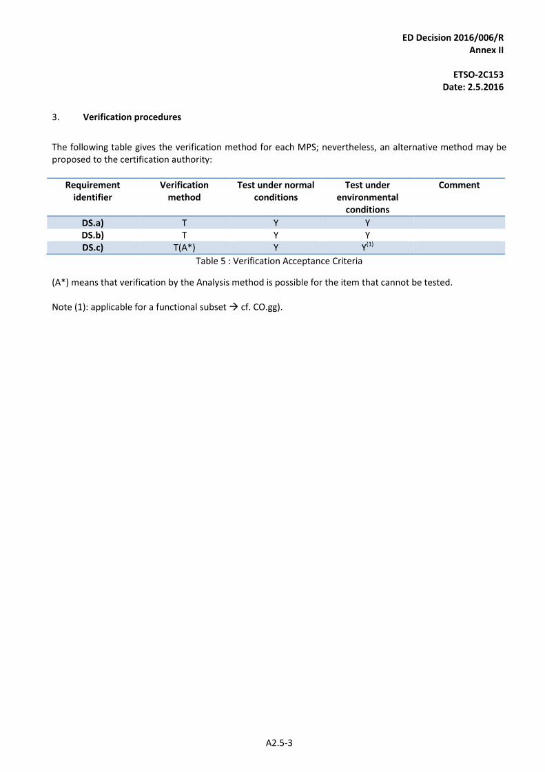
ED Decision 2016/006/R Annex II
ETSO-2C153
Date: 2.5.2016
A2.5-3
3. Verification procedures
The following table gives the verification method for each MPS; nevertheless, an alternative method may be proposed to the certification authority:
Requirement identifier
Verification method
Test under normal conditions
Test under environmental
conditions
Comment
DS.a) T Y Y DS.b) T Y Y DS.c) T(A*) Y Y(1)
Table 5 : Verification Acceptance Criteria
(A*) means that verification by the Analysis method is possible for the item that cannot be tested. Note (1): applicable for a functional subset cf. CO.gg).
ED Decision 2016/006/R Annex II
ETSO-2C153
Date: 2.5.2016
A2.6-1
APPENDIX 2.6
INTEGRATED MODULAR AVIONICS (IMA) MODULE MINIMUM PERFORMANCE SPECIFICATION (MPS)
CLASS IF: Interface
1. Purpose and scope
Introduction 1.1.
This Appendix contains Minimum Performance Standards (MPS) for CLASS IF Intended Function: Interface. These standards specify characteristics that should be useful to designers, manufacturers, installers and users of the IMA module.
Definitions 1.2.
For ETSO-2C153 CLASS IF, the IMA module provides shared resources in terms of interfaces between hosted applications, modules and/or components. Following definitions are used:
— Interface Unit: a set of hardware and/or software components in charge of supplying and managing a shared information resource.
— Data Thread: a well-defined set of data which is a primary form of information and for which a level of isolation would be guaranteed by the IMA module.
Each data thread handled by the Interface, if so wished by the applicant, may be bidirectional or symmetrical between interconnected components, modules, or hosted applications. In the context of IF class, the ‘concurrent item’ defined in Appendix 2.1, paragraph 1 means ‘Data Thread’.
Intended Function 1.3.
For ETSO-2C153 CLASS IF, the intended function is to provide the capability to share information supplied by one or several interfaces units. This intended function is Information Sharing composed of:
— information acquisition and control;
— information conversion and; and
— information forwarding and control.
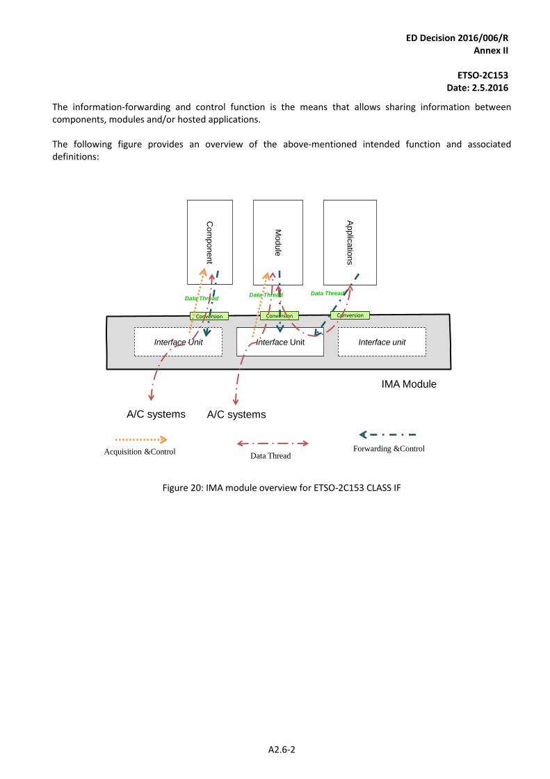
ED Decision 2016/006/R Annex II
ETSO-2C153
Date: 2.5.2016
A2.6-2
The information-forwarding and control function is the means that allows sharing information between components, modules and/or hosted applications. The following figure provides an overview of the above-mentioned intended function and associated definitions:
ConversionConversion
IMA Module
Interface unitC
om
ponent
Applic
atio
ns
Module
Interface UnitInterface Unit
Data Thread
Conversion
Data ThreadData Thread
Acquisition &Control Forwarding &ControlData Thread
A/C systems A/C systems
Figure 20: IMA module overview for ETSO-2C153 CLASS IF
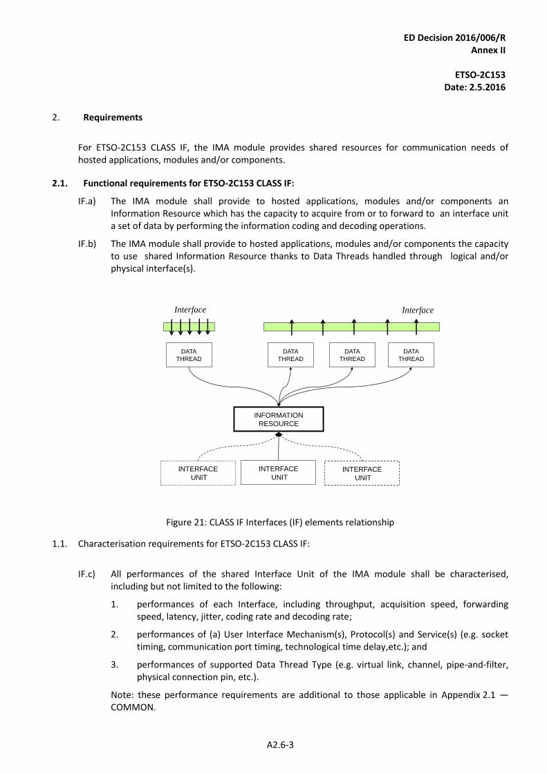
ED Decision 2016/006/R Annex II
ETSO-2C153
Date: 2.5.2016
A2.6-3
2. Requirements
For ETSO-2C153 CLASS IF, the IMA module provides shared resources for communication needs of hosted applications, modules and/or components.
Functional requirements for ETSO-2C153 CLASS IF: 2.1.
IF.a) The IMA module shall provide to hosted applications, modules and/or components an Information Resource which has the capacity to acquire from or to forward to an interface unit a set of data by performing the information coding and decoding operations.
IF.b) The IMA module shall provide to hosted applications, modules and/or components the capacity to use shared Information Resource thanks to Data Threads handled through logical and/or physical interface(s).
INTERFACE
UNIT
INTERFACE
UNITINTERFACE
UNIT
INFORMATION
RESOURCE
DATA
THREAD
DATA
THREAD
DATA
THREAD
DATA
THREAD
Interface Interface
Figure 21: CLASS IF Interfaces (IF) elements relationship
1.1. Characterisation requirements for ETSO-2C153 CLASS IF:
IF.c) All performances of the shared Interface Unit of the IMA module shall be characterised, including but not limited to the following:
1. performances of each Interface, including throughput, acquisition speed, forwarding speed, latency, jitter, coding rate and decoding rate;
2. performances of (a) User Interface Mechanism(s), Protocol(s) and Service(s) (e.g. socket timing, communication port timing, technological time delay,etc.); and
3. performances of supported Data Thread Type (e.g. virtual link, channel, pipe-and-filter, physical connection pin, etc.).
Note: these performance requirements are additional to those applicable in Appendix 2.1 — COMMON.
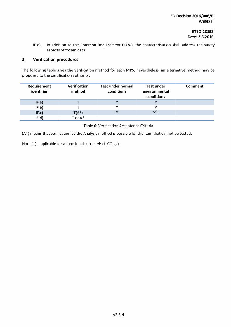
ED Decision 2016/006/R Annex II
ETSO-2C153
Date: 2.5.2016
A2.6-4
IF.d) In addition to the Common Requirement CO.w), the characterisation shall address the safety aspects of frozen data.
2. Verification procedures The following table gives the verification method for each MPS; nevertheless, an alternative method may be proposed to the certification authority:
Requirement identifier
Verification method
Test under normal conditions
Test under environmental
conditions
Comment
IF.a) T Y Y IF.b) T Y Y IF.c) T(A*) Y Y(1) IF.d) T or A*
Table 6: Verification Acceptance Criteria
(A*) means that verification by the Analysis method is possible for the item that cannot be tested. Note (1): applicable for a functional subset cf. CO.gg).
ED Decision 2016/006/R Annex II
ETSO-2C153
Date: 2.5.2016
A2.7-1
APPENDIX 2.7
INTEGRATED MODULAR AVIONICS (IMA) PLATFORM AND MODULE MINIMUM PERFORMANCE SPECIFICATION (MPS)
CLASS PS: Power Supply (PS)
1. Purpose and scope
Introduction 1.1.
This Appendix contains Minimum Performance Standards (MPSs) for CLASS PS Intended Function: Power Supply (PS) These standards specify module characteristics that should be useful to designers, manufacturers, installers and users of the module.
Definitions 1.2.
For ETSO-2C153 CLASS PS, the IMA module is a module, mounted into a rack or the rack itself, able to supply power received from the aircraft electrical network to one or more hardware modules mounted in the same rack. The following definitions are used:
— Power supply unit: a set of physical components (hardware and or software) in charge of managing a power supply (or a part of the power supply) resource.
— Power supply resource : obtained electrical energy from the aircraft electrical network to be distributed to electrical loads which are modules mounted into the rack.
— Power rail: a part of supplied electrical energy for which a level of isolation is guaranteed by the IMA module.
— Mounted: it refers to another hardware module installed and fixed inside the IMA Rack Module after a manual operation.
— Slot : a physical space inside the Rack Module allocated to one hardware module.
— Hold-up Capacity: The capacity of the power supply to continue supplying output current after the input voltage drops below the minimum level. This is usually expressed as the time from the input voltage drop to the reset generated by the power supply to the processor.
— Output Current Capacity: the continuously operating maximum current supplied for each output voltage.
— Power Monitors & Status Outputs: a separate circuitry which checks the output voltage levels and current loading of the power supply. This circuitry will generate one or more binary signals that may be connected to the processor to alert it to the ‘out of spec’ condition. These binary signals may also force the power supply to shutdown to prevent damage to power supply components.
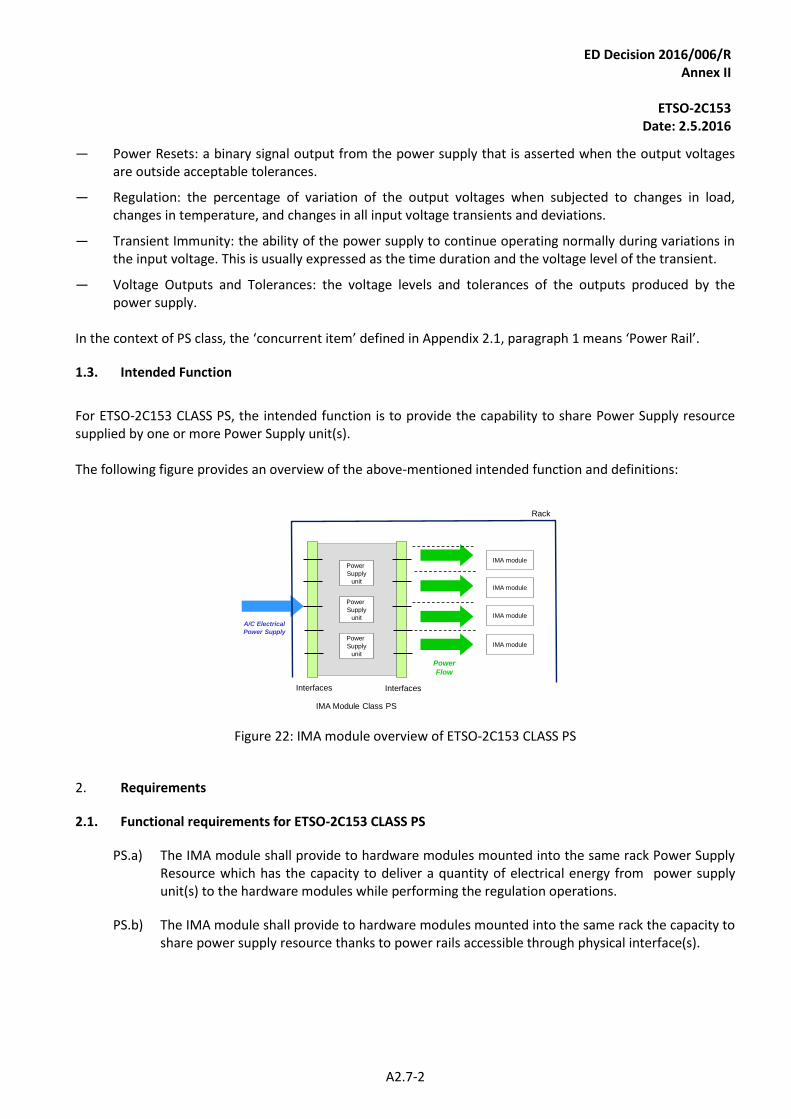
ED Decision 2016/006/R Annex II
ETSO-2C153
Date: 2.5.2016
A2.7-2
— Power Resets: a binary signal output from the power supply that is asserted when the output voltages are outside acceptable tolerances.
— Regulation: the percentage of variation of the output voltages when subjected to changes in load, changes in temperature, and changes in all input voltage transients and deviations.
— Transient Immunity: the ability of the power supply to continue operating normally during variations in the input voltage. This is usually expressed as the time duration and the voltage level of the transient.
— Voltage Outputs and Tolerances: the voltage levels and tolerances of the outputs produced by the power supply.
In the context of PS class, the ‘concurrent item’ defined in Appendix 2.1, paragraph 1 means ‘Power Rail’.
Intended Function 1.3.
For ETSO-2C153 CLASS PS, the intended function is to provide the capability to share Power Supply resource supplied by one or more Power Supply unit(s). The following figure provides an overview of the above-mentioned intended function and definitions:
A/C Electrical
Power Supply
Interfaces
IMA Module Class PS
Power
Supply
unit
Power
Flow
Power
Supply
unit
Power
Supply
unit
Interfaces
IMA module
IMA module
IMA module
IMA module
Rack
Figure 22: IMA module overview of ETSO-2C153 CLASS PS
2. Requirements
Functional requirements for ETSO-2C153 CLASS PS 2.1.
PS.a) The IMA module shall provide to hardware modules mounted into the same rack Power Supply Resource which has the capacity to deliver a quantity of electrical energy from power supply unit(s) to the hardware modules while performing the regulation operations.
PS.b) The IMA module shall provide to hardware modules mounted into the same rack the capacity to share power supply resource thanks to power rails accessible through physical interface(s).
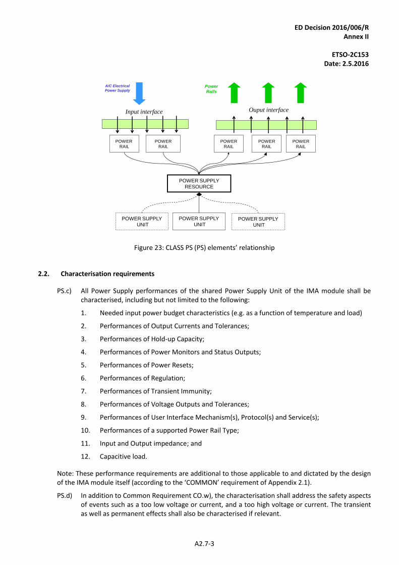
ED Decision 2016/006/R Annex II
ETSO-2C153
Date: 2.5.2016
A2.7-3
POWER SUPPLY
UNIT
POWER SUPPLY
UNITPOWER SUPPLY
UNIT
POWER SUPPLY
RESOURCE
POWER
RAIL
POWER
RAIL
Input interface
POWER
RAIL
POWER
RAIL
POWER
RAIL
Ouput interface
A/C Electrical
Power SupplyPower
Rails
Figure 23: CLASS PS (PS) elements’ relationship
Characterisation requirements 2.2.
PS.c) All Power Supply performances of the shared Power Supply Unit of the IMA module shall be characterised, including but not limited to the following:
1. Needed input power budget characteristics (e.g. as a function of temperature and load)
2. Performances of Output Currents and Tolerances;
3. Performances of Hold-up Capacity;
4. Performances of Power Monitors and Status Outputs;
5. Performances of Power Resets;
6. Performances of Regulation;
7. Performances of Transient Immunity;
8. Performances of Voltage Outputs and Tolerances;
9. Performances of User Interface Mechanism(s), Protocol(s) and Service(s);
10. Performances of a supported Power Rail Type;
11. Input and Output impedance; and
12. Capacitive load.
Note: These performance requirements are additional to those applicable to and dictated by the design of the IMA module itself (according to the ‘COMMON’ requirement of Appendix 2.1).
PS.d) In addition to Common Requirement CO.w), the characterisation shall address the safety aspects of events such as a too low voltage or current, and a too high voltage or current. The transient as well as permanent effects shall also be characterised if relevant.
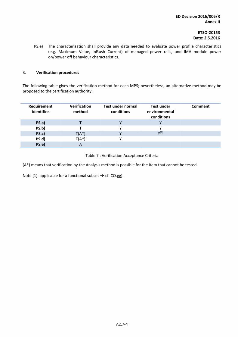
ED Decision 2016/006/R Annex II
ETSO-2C153
Date: 2.5.2016
A2.7-4
PS.e) The characterisation shall provide any data needed to evaluate power profile characteristics (e.g. Maximum Value, InRush Current) of managed power rails, and IMA module power on/power off behaviour characteristics.
3. Verification procedures
The following table gives the verification method for each MPS; nevertheless, an alternative method may be proposed to the certification authority:
Requirement identifier
Verification method
Test under normal conditions
Test under environmental
conditions
Comment
PS.a) T Y Y PS.b) T Y Y PS.c) T(A*) Y Y(1) PS.d) T(A*) Y PS.e) A
Table 7 : Verification Acceptance Criteria
(A*) means that verification by the Analysis method is possible for the item that cannot be tested. Note (1): applicable for a functional subset cf. CO.gg).
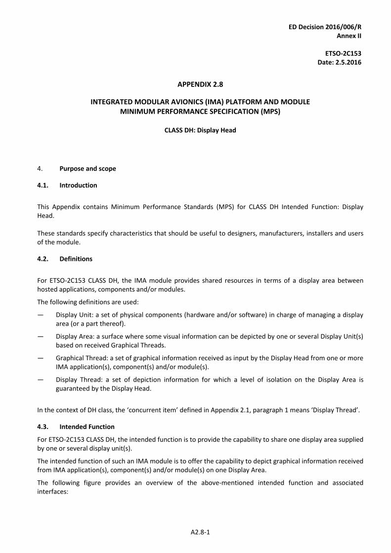
ED Decision 2016/006/R Annex II
ETSO-2C153
Date: 2.5.2016
A2.8-1
APPENDIX 2.8
INTEGRATED MODULAR AVIONICS (IMA) PLATFORM AND MODULE MINIMUM PERFORMANCE SPECIFICATION (MPS)
CLASS DH: Display Head
4. Purpose and scope
Introduction 4.1.
This Appendix contains Minimum Performance Standards (MPS) for CLASS DH Intended Function: Display Head. These standards specify characteristics that should be useful to designers, manufacturers, installers and users of the module.
Definitions 4.2.
For ETSO-2C153 CLASS DH, the IMA module provides shared resources in terms of a display area between hosted applications, components and/or modules.
The following definitions are used:
— Display Unit: a set of physical components (hardware and/or software) in charge of managing a display area (or a part thereof).
— Display Area: a surface where some visual information can be depicted by one or several Display Unit(s) based on received Graphical Threads.
— Graphical Thread: a set of graphical information received as input by the Display Head from one or more IMA application(s), component(s) and/or module(s).
— Display Thread: a set of depiction information for which a level of isolation on the Display Area is guaranteed by the Display Head.
In the context of DH class, the ‘concurrent item’ defined in Appendix 2.1, paragraph 1 means ‘Display Thread’.
Intended Function 4.3.
For ETSO-2C153 CLASS DH, the intended function is to provide the capability to share one display area supplied by one or several display unit(s).
The intended function of such an IMA module is to offer the capability to depict graphical information received from IMA application(s), component(s) and/or module(s) on one Display Area.
The following figure provides an overview of the above-mentioned intended function and associated interfaces:
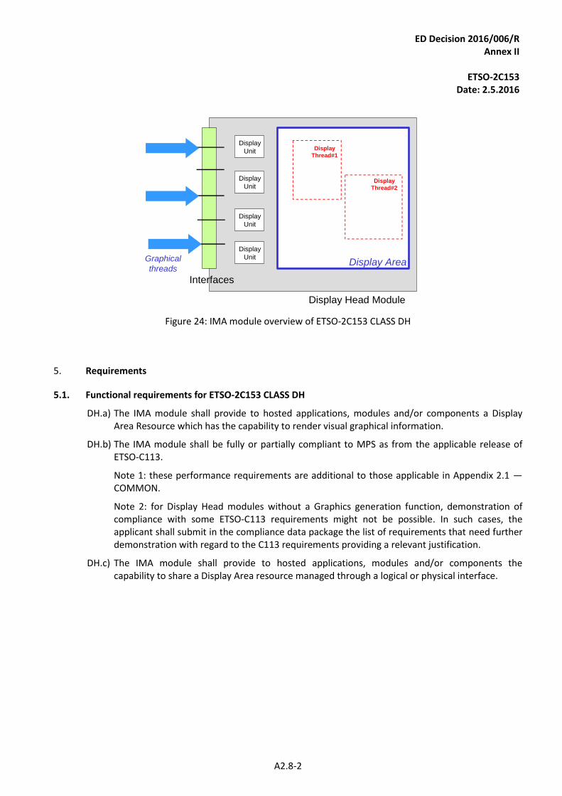
ED Decision 2016/006/R Annex II
ETSO-2C153
Date: 2.5.2016
A2.8-2
Display
Thread#1
Display
Thread#2
Display AreaGraphical
threads
Interfaces
Display Head Module
Display
Unit
Display
Unit
Display
Unit
Display
Unit
Figure 24: IMA module overview of ETSO-2C153 CLASS DH
5. Requirements
Functional requirements for ETSO-2C153 CLASS DH 5.1.
DH.a) The IMA module shall provide to hosted applications, modules and/or components a Display Area Resource which has the capability to render visual graphical information.
DH.b) The IMA module shall be fully or partially compliant to MPS as from the applicable release of ETSO-C113.
Note 1: these performance requirements are additional to those applicable in Appendix 2.1 — COMMON.
Note 2: for Display Head modules without a Graphics generation function, demonstration of compliance with some ETSO-C113 requirements might not be possible. In such cases, the applicant shall submit in the compliance data package the list of requirements that need further demonstration with regard to the C113 requirements providing a relevant justification.
DH.c) The IMA module shall provide to hosted applications, modules and/or components the capability to share a Display Area resource managed through a logical or physical interface.
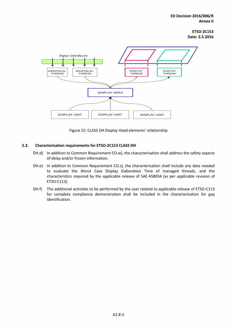
ED Decision 2016/006/R Annex II
ETSO-2C153
Date: 2.5.2016
A2.8-3
DISPLAY UNIT DISPLAY UNIT DISPLAY UNIT
DISPLAY AREA
DISPLAY
THREAD
DISPLAY
THREAD
GRAPHICAL
THREAD
GRAPHICAL
THREAD
Input interfaces
Figure 25: CLASS DH Display Head elements’ relationship
Characterisation requirements for ETSO-2C153 CLASS DH 5.2.
DH.d) In addition to Common Requirement CO.w), the characterisation shall address the safety aspects of delay and/or frozen information.
DH.e) In addition to Common Requirement CO.s), the characterisation shall include any data needed to evaluate the Worst Case Display Elaboration Time of managed threads, and the characteristics required by the applicable release of SAE AS8034 (as per applicable revision of ETSO-C113).
DH.f) The additional activities to be performed by the user related to applicable release of ETSO-C113 for complete compliance demonstration shall be included in the characterisation for gap identification.
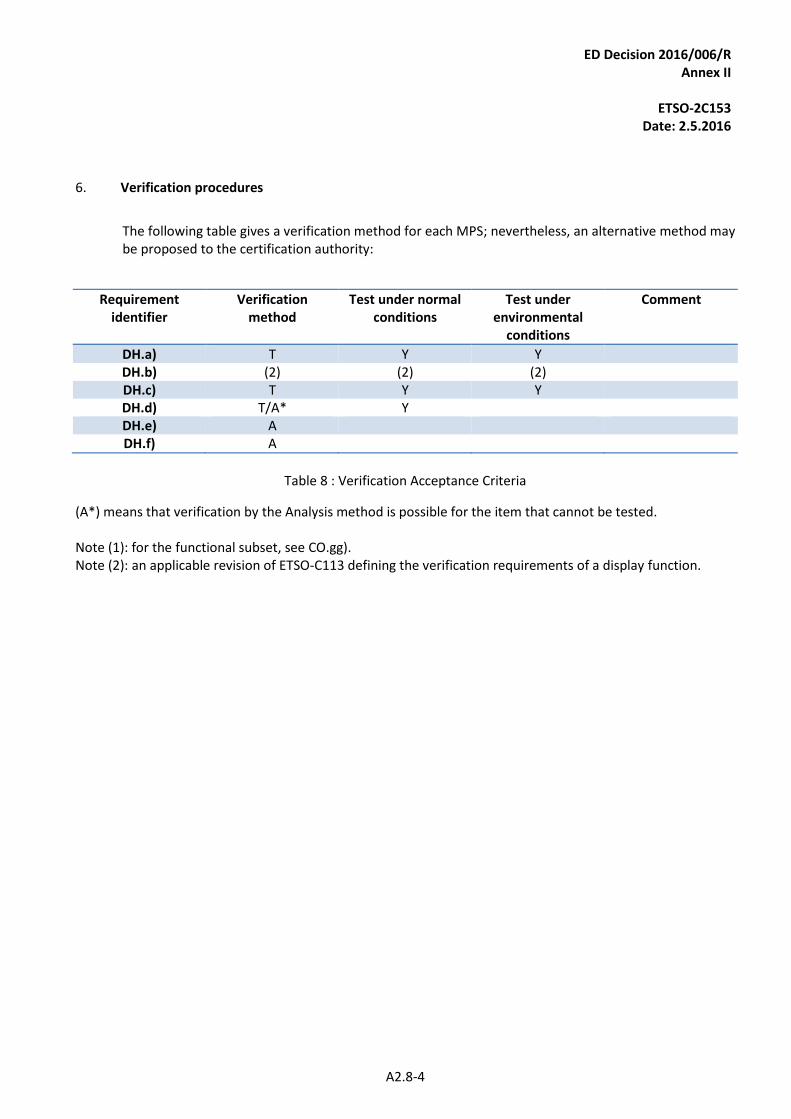
ED Decision 2016/006/R Annex II
ETSO-2C153
Date: 2.5.2016
A2.8-4
6. Verification procedures
The following table gives a verification method for each MPS; nevertheless, an alternative method may be proposed to the certification authority:
Requirement identifier
Verification method
Test under normal conditions
Test under environmental
conditions
Comment
DH.a) T Y Y DH.b) (2) (2) (2) DH.c) T Y Y DH.d) T/A* Y DH.e) A DH.f) A
Table 8 : Verification Acceptance Criteria
(A*) means that verification by the Analysis method is possible for the item that cannot be tested. Note (1): for the functional subset, see CO.gg). Note (2): an applicable revision of ETSO-C113 defining the verification requirements of a display function.
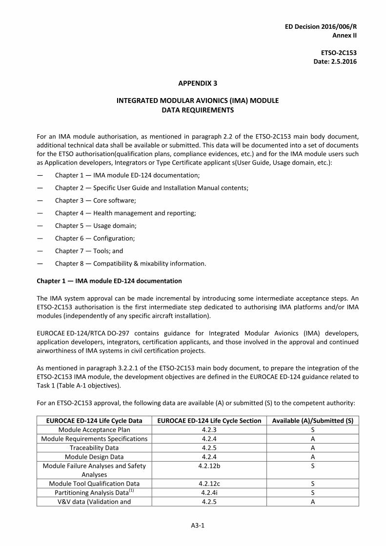
ED Decision 2016/006/R Annex II
ETSO-2C153
Date: 2.5.2016
A3-1
APPENDIX 3
INTEGRATED MODULAR AVIONICS (IMA) MODULE DATA REQUIREMENTS
For an IMA module authorisation, as mentioned in paragraph 2.2 of the ETSO-2C153 main body document, additional technical data shall be available or submitted. This data will be documented into a set of documents for the ETSO authorisation(qualification plans, compliance evidences, etc.) and for the IMA module users such as Application developers, Integrators or Type Certificate applicant s(User Guide, Usage domain, etc.):
— Chapter 1 — IMA module ED-124 documentation;
— Chapter 2 — Specific User Guide and Installation Manual contents;
— Chapter 3 — Core software;
— Chapter 4 — Health management and reporting;
— Chapter 5 — Usage domain;
— Chapter 6 — Configuration;
— Chapter 7 — Tools; and
— Chapter 8 — Compatibility & mixability information. Chapter 1 — IMA module ED-124 documentation The IMA system approval can be made incremental by introducing some intermediate acceptance steps. An ETSO-2C153 authorisation is the first intermediate step dedicated to authorising IMA platforms and/or IMA modules (independently of any specific aircraft installation). EUROCAE ED-124/RTCA DO-297 contains guidance for Integrated Modular Avionics (IMA) developers, application developers, integrators, certification applicants, and those involved in the approval and continued airworthiness of IMA systems in civil certification projects. As mentioned in paragraph 3.2.2.1 of the ETSO-2C153 main body document, to prepare the integration of the ETSO-2C153 IMA module, the development objectives are defined in the EUROCAE ED-124 guidance related to Task 1 (Table A-1 objectives). For an ETSO-2C153 approval, the following data are available (A) or submitted (S) to the competent authority:
EUROCAE ED-124 Life Cycle Data EUROCAE ED-124 Life Cycle Section Available (A)/Submitted (S)
Module Acceptance Plan 4.2.3 S
Module Requirements Specifications 4.2.4 A
Traceability Data 4.2.5 A
Module Design Data 4.2.4 A
Module Failure Analyses and Safety Analyses
4.2.12b S
Module Tool Qualification Data 4.2.12c S
Partitioning Analysis Data(1) 4.2.4i S
V&V data (Validation and 4.2.5 A
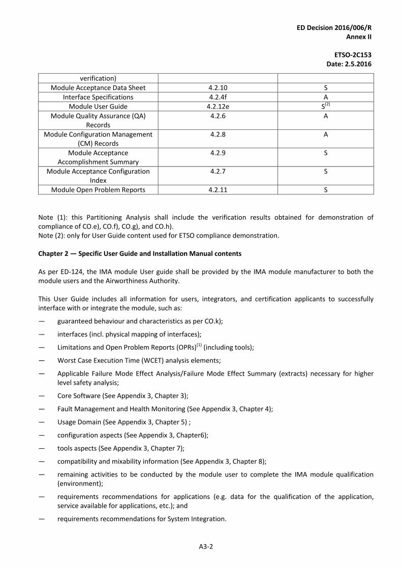
ED Decision 2016/006/R Annex II
ETSO-2C153
Date: 2.5.2016
A3-2
verification)
Module Acceptance Data Sheet 4.2.10 S
Interface Specifications 4.2.4f A
Module User Guide 4.2.12e S(2)
Module Quality Assurance (QA) Records
4.2.6 A
Module Configuration Management (CM) Records
4.2.8 A
Module Acceptance Accomplishment Summary
4.2.9 S
Module Acceptance Configuration Index
4.2.7 S
Module Open Problem Reports 4.2.11 S
Note (1): this Partitioning Analysis shall include the verification results obtained for demonstration of compliance of CO.e), CO.f), CO.g), and CO.h). Note (2): only for User Guide content used for ETSO compliance demonstration. Chapter 2 — Specific User Guide and Installation Manual contents As per ED-124, the IMA module User guide shall be provided by the IMA module manufacturer to both the module users and the Airworthiness Authority. This User Guide includes all information for users, integrators, and certification applicants to successfully interface with or integrate the module, such as:
— guaranteed behaviour and characteristics as per CO.k);
— interfaces (incl. physical mapping of interfaces);
— Limitations and Open Problem Reports (OPRs)(1) (including tools);
— Worst Case Execution Time (WCET) analysis elements;
— Applicable Failure Mode Effect Analysis/Failure Mode Effect Summary (extracts) necessary for higher level safety analysis;
— Core Software (See Appendix 3, Chapter 3);
— Fault Management and Health Monitoring (See Appendix 3, Chapter 4);
— Usage Domain (See Appendix 3, Chapter 5) ;
— configuration aspects (See Appendix 3, Chapter6);
— tools aspects (See Appendix 3, Chapter 7);
— compatibility and mixability information (See Appendix 3, Chapter 8);
— remaining activities to be conducted by the module user to complete the IMA module qualification (environment);
— requirements recommendations for applications (e.g. data for the qualification of the application, service available for applications, etc.); and
— requirements recommendations for System Integration.
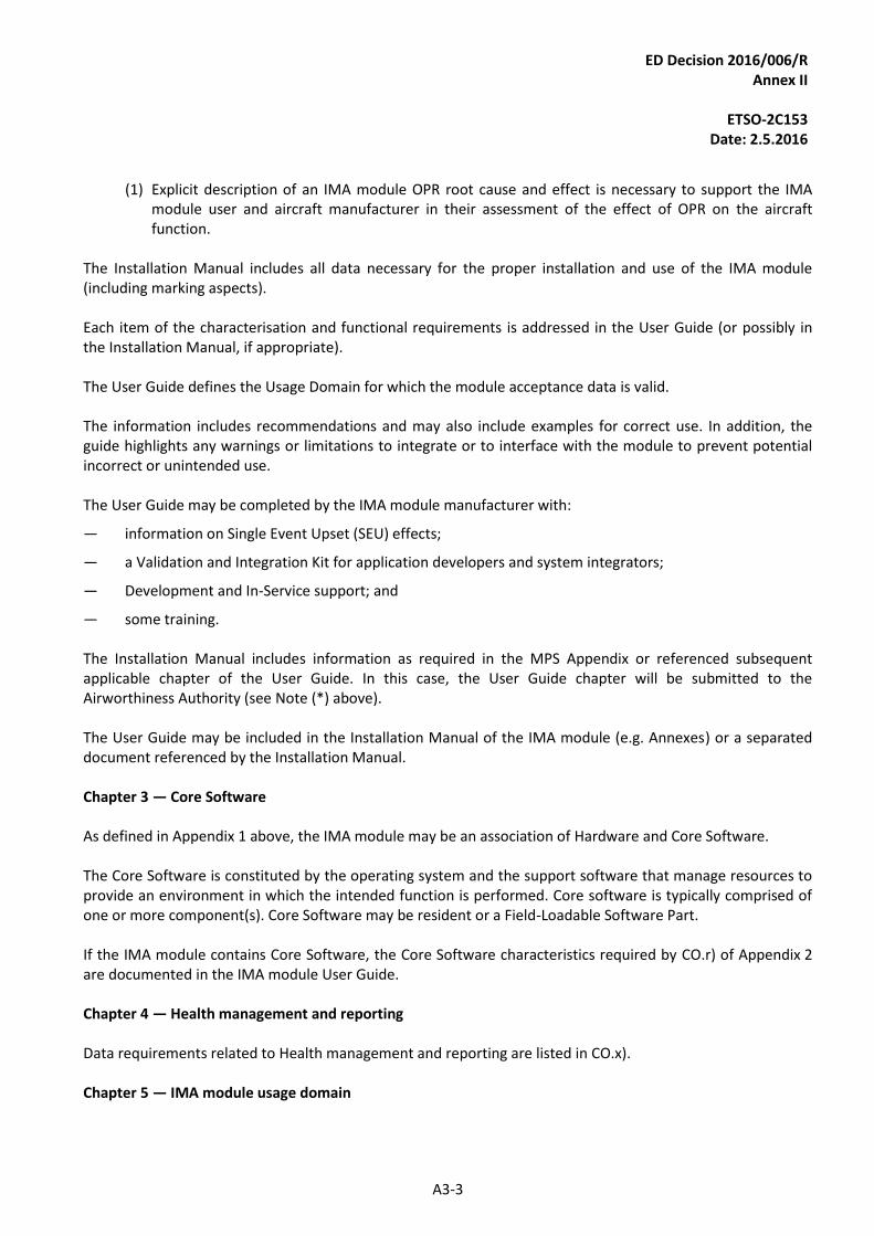
ED Decision 2016/006/R Annex II
ETSO-2C153
Date: 2.5.2016
A3-3
(1) Explicit description of an IMA module OPR root cause and effect is necessary to support the IMA
module user and aircraft manufacturer in their assessment of the effect of OPR on the aircraft function.
The Installation Manual includes all data necessary for the proper installation and use of the IMA module (including marking aspects). Each item of the characterisation and functional requirements is addressed in the User Guide (or possibly in the Installation Manual, if appropriate).
The User Guide defines the Usage Domain for which the module acceptance data is valid. The information includes recommendations and may also include examples for correct use. In addition, the guide highlights any warnings or limitations to integrate or to interface with the module to prevent potential incorrect or unintended use. The User Guide may be completed by the IMA module manufacturer with:
— information on Single Event Upset (SEU) effects;
— a Validation and Integration Kit for application developers and system integrators;
— Development and In-Service support; and
— some training. The Installation Manual includes information as required in the MPS Appendix or referenced subsequent applicable chapter of the User Guide. In this case, the User Guide chapter will be submitted to the Airworthiness Authority (see Note (*) above). The User Guide may be included in the Installation Manual of the IMA module (e.g. Annexes) or a separated document referenced by the Installation Manual. Chapter 3 — Core Software As defined in Appendix 1 above, the IMA module may be an association of Hardware and Core Software. The Core Software is constituted by the operating system and the support software that manage resources to provide an environment in which the intended function is performed. Core software is typically comprised of one or more component(s). Core Software may be resident or a Field-Loadable Software Part. If the IMA module contains Core Software, the Core Software characteristics required by CO.r) of Appendix 2 are documented in the IMA module User Guide.
Chapter 4 — Health management and reporting Data requirements related to Health management and reporting are listed in CO.x). Chapter 5 — IMA module usage domain
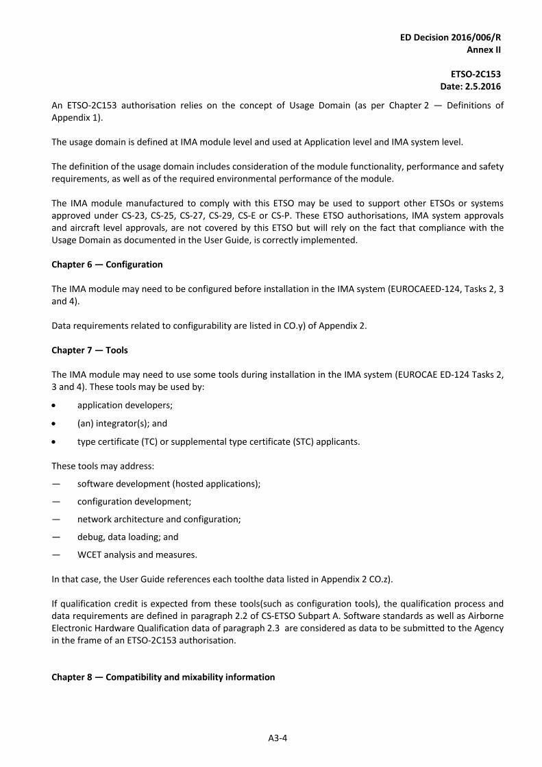
ED Decision 2016/006/R Annex II
ETSO-2C153
Date: 2.5.2016
A3-4
An ETSO-2C153 authorisation relies on the concept of Usage Domain (as per Chapter 2 — Definitions of Appendix 1).
The usage domain is defined at IMA module level and used at Application level and IMA system level. The definition of the usage domain includes consideration of the module functionality, performance and safety requirements, as well as of the required environmental performance of the module. The IMA module manufactured to comply with this ETSO may be used to support other ETSOs or systems approved under CS-23, CS-25, CS-27, CS-29, CS-E or CS-P. These ETSO authorisations, IMA system approvals and aircraft level approvals, are not covered by this ETSO but will rely on the fact that compliance with the Usage Domain as documented in the User Guide, is correctly implemented. Chapter 6 — Configuration The IMA module may need to be configured before installation in the IMA system (EUROCAEED-124, Tasks 2, 3 and 4). Data requirements related to configurability are listed in CO.y) of Appendix 2. Chapter 7 — Tools The IMA module may need to use some tools during installation in the IMA system (EUROCAE ED-124 Tasks 2, 3 and 4). These tools may be used by:
· application developers;
· (an) integrator(s); and
· type certificate (TC) or supplemental type certificate (STC) applicants. These tools may address:
— software development (hosted applications);
— configuration development;
— network architecture and configuration;
— debug, data loading; and
— WCET analysis and measures.
In that case, the User Guide references each toolthe data listed in Appendix 2 CO.z). If qualification credit is expected from these tools(such as configuration tools), the qualification process and data requirements are defined in paragraph 2.2 of CS-ETSO Subpart A. Software standards as well as Airborne Electronic Hardware Qualification data of paragraph 2.3 are considered as data to be submitted to the Agency in the frame of an ETSO-2C153 authorisation. Chapter 8 — Compatibility and mixability information
ED Decision 2016/006/R Annex II
ETSO-2C153
Date: 2.5.2016
A3-5
The IMA module manufacturer provides compatibility and mixability information between hardware, software, tools and usage domain in the User Guide, as required per CO.aa) of Appendix 2.

ED Decision 2016/006/R Annex II
ETSO-2C153
Date: 2.5.2016
A4-6
APPENDIX 4
INTEGRATED MODULAR AVIONICS (IMA) MODULE ENVIRONMENTAL QUALIFICATION REQUIREMENTS
Section 2.3 of CS-ETSO Subpart A requires performing environmental testing according to the EUROCAE ED-14/RTCA DO-160 appropriate releases. For ETSO-2C153, some particularities have to be addressed:
· Test Software representativeness;
· Applicable Test Procedures; and
· parameters to be monitored during the Environmental Qualification Test.
Chapter 1 — Test Software representativeness
In case the IMA module is qualified without the functional software installed and operating, engineering analysis from the manufacturer must determine that the Test Software (not the target functional software) is representative of the usage domain stress envelop for the environmental tests (i.e. dissipated temperature, power consumption, field radiation, etc.). Test Software shall be developed to exercise the Hardware in performing the environmental tests in the worst-case conditions and/or most sensitive configurations in order to evaluate the robustness of the IMA module over the full Usage Domain. For example, the Test Software should exercise all physical interfaces; a maximum number of applications or input filter values should be set to the domain boundary that would be the most transparent to input electrical interferences. Chapter 2 — Applicable Test Procedures
For an ETSO-2C153 authorisation, the IMA module may be a single Line Replaceable Unit (LRU) platform or may be a Line Replaceable Module (LRM) located in a Rack. Two cases have to be considered depending on the IMA module characteristics:
· Case 1: the IMA module is a single LRU platform; and
· Case 2: the IMA module is a module designed to be located in a Rack at installation. Note: the Rack Housing module is not addressed in this generic Appendix but in the relevant Appendix 2.2 — Class RH: Rack Housing. Chapter 2.1 — The IMA module is a single LRU platform In this case, the environmental sections defined in the Table below (Figure 26) are applicable to the IMA module.
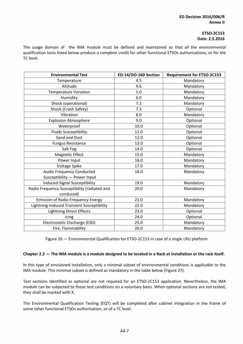
ED Decision 2016/006/R Annex II
ETSO-2C153
Date: 2.5.2016
A4-7
The usage domain of the IMA module must be defined and maintained so that all the environmental qualification tests listed below produce a complete credit for other functional ETSOs authorisations, or for the TC level.
Environmental Test ED-14/DO-160 Section Requirement for ETSO-2C153
Temperature 4.5 Mandatory
Altitude 4.6 Mandatory
Temperature Variation 5.0 Mandatory
Humidity 6.0 Mandatory
Shock (operational) 7.2 Mandatory
Shock (Crash Safety) 7.3 Optional
Vibration 8.0 Mandatory
Explosion Atmosphere 9.0 Optional
Waterproof 10.0 Optional
Fluids Susceptibility 11.0 Optional
Sand and Dust 12.0 Optional
Fungus Resistance 13.0 Optional
Salt Fog 14.0 Optional
Magnetic Effect 15.0 Mandatory
Power Input 16.0 Mandatory
Voltage Spike 17.0 Mandatory
Audio Frequency Conducted Susceptibility — Power Input
18.0 Mandatory
Induced-Signal Susceptibility 19.0 Mandatory
Radio Frequency Susceptibility (radiated and conduced)
20.0 Mandatory
Emission of Radio Frequency Energy 21.0 Mandatory
Lightning-Induced Transient Susceptibility 22.0 Mandatory
Lightning Direct Effects 23.0 Optional
Icing 24.0 Optional
Electrostatic Discharge (ESD) 25.0 Mandatory
Fire, Flammability 26.0 Mandatory
Figure 26 — Environmental Qualification for ETSO-2C153 in case of a single LRU platform
Chapter 2.2 — The IMA module is a module designed to be located in a Rack at installation or the rack itself. In this type of envisioned installation, only a minimal subset of environmental conditions is applicable to the IMA module. This minimal subset is defined as mandatory in the table below (Figure 27). Test sections identified as optional are not required for an ETSO-2C153 application. Nevertheless, the IMA module can be subjected to these test conditions on a voluntary basis. When optional sections are not tested, they shall be marked with X. The Environmental Qualification Testing (EQT) will be completed after cabinet integration in the frame of some other functional ETSOs authorisation, or of a TC level.
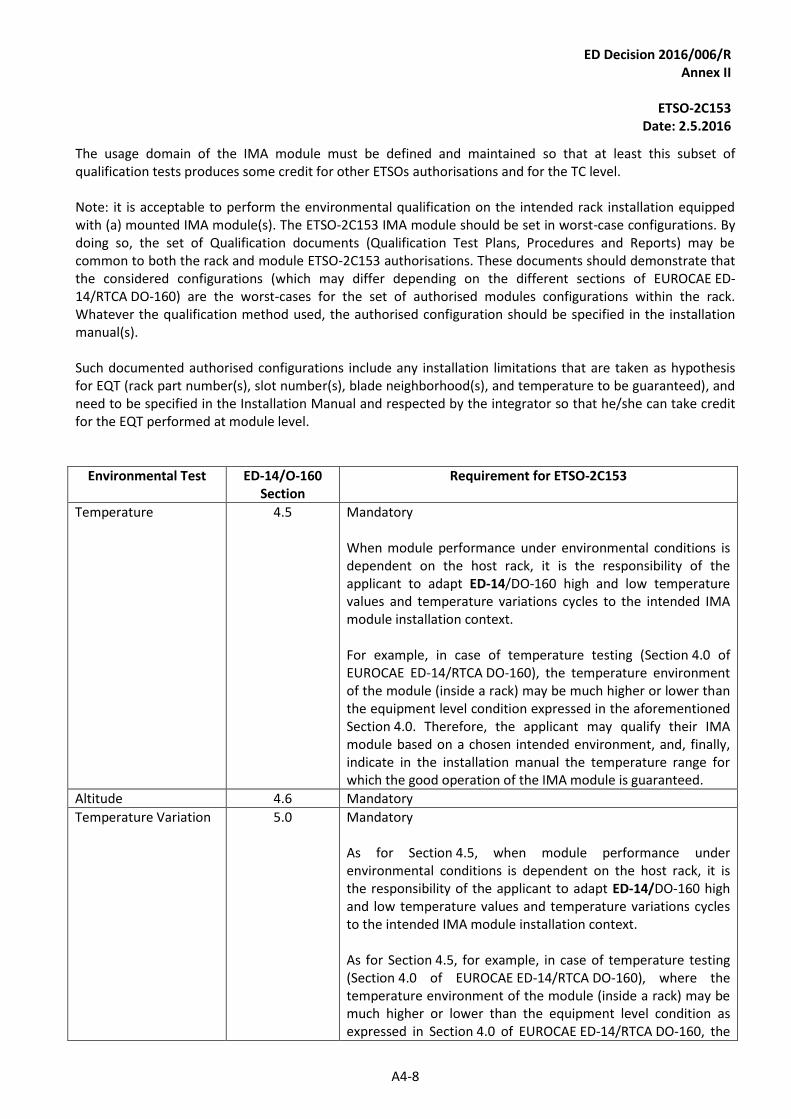
ED Decision 2016/006/R Annex II
ETSO-2C153
Date: 2.5.2016
A4-8
The usage domain of the IMA module must be defined and maintained so that at least this subset of qualification tests produces some credit for other ETSOs authorisations and for the TC level. Note: it is acceptable to perform the environmental qualification on the intended rack installation equipped with (a) mounted IMA module(s). The ETSO-2C153 IMA module should be set in worst-case configurations. By doing so, the set of Qualification documents (Qualification Test Plans, Procedures and Reports) may be common to both the rack and module ETSO-2C153 authorisations. These documents should demonstrate that the considered configurations (which may differ depending on the different sections of EUROCAE ED-14/RTCA DO-160) are the worst-cases for the set of authorised modules configurations within the rack. Whatever the qualification method used, the authorised configuration should be specified in the installation manual(s). Such documented authorised configurations include any installation limitations that are taken as hypothesis for EQT (rack part number(s), slot number(s), blade neighborhood(s), and temperature to be guaranteed), and need to be specified in the Installation Manual and respected by the integrator so that he/she can take credit for the EQT performed at module level.
Environmental Test ED-14/O-160 Section
Requirement for ETSO-2C153
Temperature 4.5 Mandatory When module performance under environmental conditions is dependent on the host rack, it is the responsibility of the applicant to adapt ED-14/DO-160 high and low temperature values and temperature variations cycles to the intended IMA module installation context. For example, in case of temperature testing (Section 4.0 of EUROCAE ED-14/RTCA DO-160), the temperature environment of the module (inside a rack) may be much higher or lower than the equipment level condition expressed in the aforementioned Section 4.0. Therefore, the applicant may qualify their IMA module based on a chosen intended environment, and, finally, indicate in the installation manual the temperature range for which the good operation of the IMA module is guaranteed.
Altitude 4.6 Mandatory
Temperature Variation 5.0 Mandatory As for Section 4.5, when module performance under environmental conditions is dependent on the host rack, it is the responsibility of the applicant to adapt ED-14/DO-160 high and low temperature values and temperature variations cycles to the intended IMA module installation context. As for Section 4.5, for example, in case of temperature testing (Section 4.0 of EUROCAE ED-14/RTCA DO-160), where the temperature environment of the module (inside a rack) may be much higher or lower than the equipment level condition as expressed in Section 4.0 of EUROCAE ED-14/RTCA DO-160, the
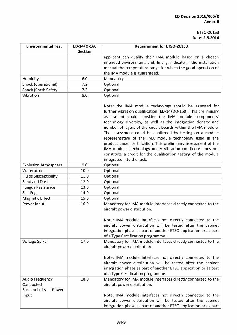
ED Decision 2016/006/R Annex II
ETSO-2C153
Date: 2.5.2016
A4-9
Environmental Test ED-14/O-160 Section
Requirement for ETSO-2C153
applicant can qualify their IMA module based on a chosen intended environment, and, finally, indicate in the installation manual the temperature range for which the good operation of the IMA module is guaranteed.
Humidity 6.0 Mandatory
Shock (operational) 7.2 Optional
Shock (Crash Safety) 7.3 Optional
Vibration 8.0 Optional Note: the IMA module technology should be assessed for further vibration qualification (ED-14/DO-160). This preliminary assessment could consider the IMA module components’ technology diversity, as well as the integration density and number of layers of the circuit boards within the IMA module. The assessment could be confirmed by testing on a module representative of the IMA module technology used in the product under certification. This preliminary assessment of the IMA module technology under vibration conditions does not constitute a credit for the qualification testing of the module integrated into the rack.
Explosion Atmosphere 9.0 Optional
Waterproof 10.0 Optional
Fluids Susceptibility 11.0 Optional
Sand and Dust 12.0 Optional
Fungus Resistance 13.0 Optional
Salt Fog 14.0 Optional
Magnetic Effect 15.0 Optional
Power Input 16.0 Mandatory for IMA module interfaces directly connected to the aircraft power distribution. Note: IMA module interfaces not directly connected to the aircraft power distribution will be tested after the cabinet integration phase as part of another ETSO application or as part of a Type Certification programme.
Voltage Spike 17.0 Mandatory for IMA module interfaces directly connected to the aircraft power distribution. Note: IMA module interfaces not directly connected to the aircraft power distribution will be tested after the cabinet integration phase as part of another ETSO application or as part of a Type Certification programme.
Audio Frequency Conducted Susceptibility — Power Input
18.0 Mandatory for IMA module interfaces directly connected to the aircraft power distribution. Note: IMA module interfaces not directly connected to the aircraft power distribution will be tested after the cabinet integration phase as part of another ETSO application or as part
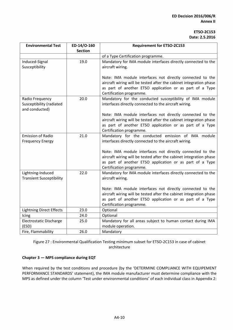
ED Decision 2016/006/R Annex II
ETSO-2C153
Date: 2.5.2016
A4-10
Environmental Test ED-14/O-160 Section
Requirement for ETSO-2C153
of a Type Certification programme.
Induced-Signal Susceptibility
19.0 Mandatory for IMA module interfaces directly connected to the aircraft wiring. Note: IMA module interfaces not directly connected to the aircraft wiring will be tested after the cabinet integration phase as part of another ETSO application or as part of a Type Certification programme.
Radio Frequency Susceptibility (radiated and conducted)
20.0 Mandatory for the conducted susceptibility of IMA module interfaces directly connected to the aircraft wiring. Note: IMA module interfaces not directly connected to the aircraft wiring will be tested after the cabinet integration phase as part of another ETSO application or as part of a Type Certification programme.
Emission of Radio Frequency Energy
21.0 Mandatory for the conducted emission of IMA module interfaces directly connected to the aircraft wiring. Note: IMA module interfaces not directly connected to the aircraft wiring will be tested after the cabinet integration phase as part of another ETSO application or as part of a Type Certification programme.
Lightning-Induced Transient Susceptibility
22.0 Mandatory for IMA module interfaces directly connected to the aircraft wiring. Note: IMA module interfaces not directly connected to the aircraft wiring will be tested after the cabinet integration phase as part of another ETSO application or as part of a Type Certification programme.
Lightning Direct Effects 23.0 Optional
Icing 24.0 Optional
Electrostatic Discharge (ESD)
25.0 Mandatory for all areas subject to human contact during IMA module operation.
Fire, Flammability 26.0 Mandatory
Figure 27 : Environmental Qualification Testing minimum subset for ETSO-2C153 in case of cabinet architecture
Chapter 3 — MPS compliance during EQT
When required by the test conditions and procedure (by the ‘DETERMINE COMPLIANCE WITH EQUIPEMENT PERFORMANCE STANDARDS’ statement), the IMA module manufacturer must determine compliance with the MPS as defined under the column ‘Test under environmental conditions’ of each individual class in Appendix 2:
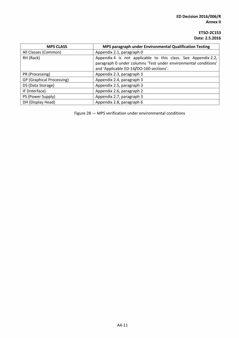
ED Decision 2016/006/R Annex II
ETSO-2C153
Date: 2.5.2016
A4-11
MPS CLASS MPS paragraph under Environmental Qualification Testing
All Classes (Common) Appendix 2.1, paragraph 0
RH (Rack) Appendix 4 is not applicable to this class. See Appendix 2.2, paragraph 0 under columns ‘Test under environmental conditions’ and ‘Applicable ED-14/DO-160 sections’.
PR (Processing) Appendix 2.3, paragraph 3
GP (Graphical Processing) Appendix 2.4, paragraph 3
DS (Data Storage) Appendix 2.5, paragraph 3
IF (Interface) Appendix 2.6, paragraph 2
PS (Power Supply) Appendix 2.7, paragraph 3
DH (Display Head) Appendix 2.8, paragraph 6
Figure 28 — MPS verification under environmental conditions