Embed Size (px)
Citation preview
1
ftmtestiamrphg
sastattevTtbd
tbtcim
iJ2
J
Downloaded Fr
Gen Satohe-mail: [email protected]
Andrew Birnbaume-mail: [email protected]
Y. Lawrence Yaoe-mail: [email protected]
Department of Mechanical Engineering,Columbia University,New York, NY 10025
Annealing Effect on the ShapeMemory Properties of AmorphousNiTi Thin FilmsThin film shape memory alloys have recently become a promising material for the actua-tion of devices on the microscale such as micropumps and microvalves. Their utilization,however, has been limited due to the difficulty in tailoring their properties for differentapplications. Control over the transformation temperatures as well as mechanical andshape memory properties is required to enable their widespread use. This study examinesthe effects of heat treatment time and temperature on the properties of amorphous, Ti-richNiTi thin films on silicon substrates. The effects on the transformation temperatures areinvestigated through the use of temperature dependent optical microscopy and tempera-ture dependent X-ray diffraction. The indentation modulus and hardness, as well asdissipated energy and depth recovery, are obtained through nanoindentation and atomicforce microscopy. The role of microstructure and composition in altering both the me-chanical and shape memory properties of the films is discussed.�DOI: 10.1115/1.4002189�
IntroductionOriginally observed in bulk specimens, the shape memory ef-
ect �SME� and superelasticity �SE� are characteristics shared byhe class of materials called shape memory alloys �SMAs�. These
aterials generated a great deal of interest in their infancy due toheir ability to recover large deformations upon heating and tondure significant, seemingly elastic strains. Recently, thin filmhape memory alloys have gained popularity due to their smallhermal mass and thus fast response time and are of particularnterest for use in microelectromechanical devices �MEMS� asctuators due to their ability to produce large forces and displace-ents. One particular SMA, NiTi, has been the focus of extensive
esearch for biomedical applications due to its excellent biocom-atibility and good shape memory characteristics. NiTi thin filmsave been applied to various MEMS applications such as micro-rippers and microvalves �1�.
Crystallization of the amorphous thin films produced throughputtering is typically performed by furnace annealing. Furnacennealing of thin film specimens has been shown to producepecimens that exhibit shape memory properties comparable tohose of bulk materials �2�. Lee et al. �3� characterized the nucle-tion and growth of NiTi crystals in amorphous sputtered filmshrough in situ transmission electron microscopy �TEM� observa-ion. Furthermore, control over transformation temperature, recov-rable strain, and even biocompatibility has been demonstrated byarying annealing parameters and deposition conditions �4–6�.hese works, however, are limited to a small set of annealing
emperatures and times and are unable to observe the transitionetween superelastic and shape memory material responses forifferent heat treatments.
X-ray diffraction �XRD� and TEM, among others, have beenhe primary methods by which both bulk and thin film SMAs haveeen characterized. These methods have been used to determinehe crystal structure, phase transformation temperatures, and pre-ipitation behavior of annealed specimens. The increased interestn thin film SMA also requires the use of different characterization
ethods that can accurately test materials in this form. Recent
Contributed by the Manufacturing Engineering Division of ASME for publicationn the JOURNAL OF MANUFACTURING SCIENCE AND ENGINEERING. Manuscript receivedune 22, 2009; final manuscript received July 1, 2010; published online September
0, 2010. Assoc. Editor: Bin Wei.ournal of Manufacturing Science and EngineeringCopyright © 20
om: http://manufacturingscience.asmedigitalcollection.asme.org/ on 08/02
studies of the micro- and nanoscale properties of SMA such asNiTi have made use of nanoindentation for this purpose. Gall etal. �7� studied the nanoindentation response of bulk, Ni-rich, su-perelastic, single crystal NiTi in different orientations. Nanoinden-tation of thin films has also been used to determine the mechanicalproperties of sputtered and annealed films as a function of com-position and film thickness �8,9�. Nanoindentation is particularlyappealing for thin film specimens since they are not easily char-acterized by conventional means. Amorphous, Ti-rich materialsare of particular interest when considering thin films since theyform microstructures unattainable in bulk materials �10�. Thereremains to be, however, a systematic study on the effects of heattreatment, specifically temperature and dwell time, on the nanoin-dentation response of thin film Ti-rich NiTi.
In this study, the effects of aging heat treatments on amorphous,sputtered, Ti-rich NiTi films are examined to provide insight intothe evolution of their microstuctures and shape memory proper-ties. Specifically, the effects of annealing temperature and dwelltime on the transformation temperatures and mechanical andshape memory properties are characterized through the use of op-tical microscopy, X-ray diffraction, nanoindentation, and atomicforce microscopy �AFM� measurements.
2 Background
2.1 Shape Memory and Superelasticity. The SME and SEexhibited by shape memory alloys are both manifestations of areversible crystallographic shift known as the martensitic transfor-mation. A brief description of shape memory phase transforma-tions and some key relations is included in this section to supporta discussion of the experimental results.
Thermodynamically, the driving force for the transformation isthe change in free energy between the austenite and martensitestructures where the free energy for each phase can be written as�11�
G� = U + PV − TS − Fl = H� − TS �1�
where U, P, V, T, S, F, and l are the internal energy, pressure,volume, temperature, entropy, force applied to the specimen, andchange in length of the specimen, respectively. The enthalpy com-ponent of the free energy is denoted as H�. At the equilibriumtemperature, the free energy of martensite is equal to that of the
austenite, which gives the following relation at constant pressure:OCTOBER 2010, Vol. 132 / 051004-110 by ASME
/2013 Terms of Use: http://asme.org/terms
wap
EttTqeod
pttpsccspce
etslpspSbtfos
idmucda
Fd
0
Downloaded Fr
dG�A = dG�M = − SAdT − lAdF = − SMdT − lMdF �2�
here the superscripts A and M indicate the values for austenitend martensite, respectively. Therefore, at the equilibrium tem-erature and constant pressure,
d�
dT= −
�SA→M
�A→M = −�H�A→M
To����A→M �3�
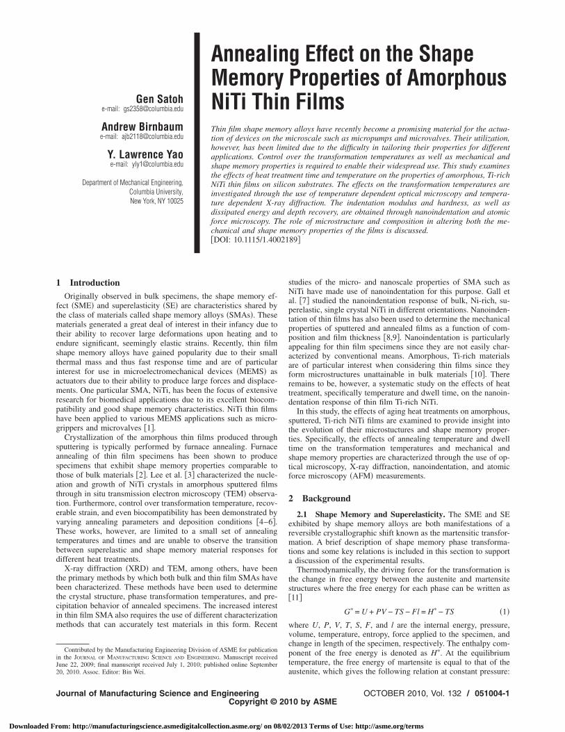
quation �3� is the Clausius–Clapeyron relationship for stress andemperature for the phase transition between austenite and mar-ensite and quantifies the change in the equilibrium temperature,o, with applied stress and conversely changes in the stress re-uired to induce the phase transformation with changes in thequilibrium temperature. Equation �3� is used to define the slopef the lines delineating the phase regions in the schematic phaseiagram of NiTi in the stress-temperature domain �Fig. 1�.
Figure 1 shows the effects of changes in transformation tem-erature on the stresses required to initiate and complete the phaseransformations, denoted as �s and �f. The material depicted byhe dashed lines is composed of twinned martensite at room tem-erature and is fully transformed to detwinned martensite at atress of �f�. The material depicted by the solid lines, however,ould be martensitic or austenitic at room temperature and will notomplete its transformation to detwinned martensite until a largertress, �f, is reached. All else being constant, these changes in thehase transformation temperatures of the materials can signifi-antly affect their responses to mechanical loading by causingither the shape memory or the superelastic response to be active.
In addition to changes between the shape memory and super-lastic responses, adjustment of phase transformation tempera-ures can cause complete loss of shape memory properties if thetress required to initiate the phase transformation becomes tooarge. For simplicity, we define the critical stress to induce thehase transformation as a single value, �mr, and �Y as the yieldtress. Materials with �mr��Y will exhibit a conventional elastic-lastic response with no shape memory or superelastic properties.ince the yield stress is below the critical stress, deformation wille accommodated by plasticity before any phase transformationakes place. Materials with �mr��Y will undergo a phase trans-ormation upon loading before reaching plasticity and, dependingn the transformation temperatures at zero stress, will exhibithape memory or superelastic properties.
2.2 Indentation and Depth Recovery. Under complex load-ng conditions such as those caused by indentation, a mixture ofeformation accommodated by phase transformation and defor-ation accommodated by plasticity is typically seen due to non-
niform stress distributions in the material. Modeling of this pro-ess begins with Hill �12�, who used an expanding cavity model toetermine the radial displacement, u�r�, of material surrounding
ig. 1 Schematic diagram of the stress-temperature phaseiagram for NiTi
n expanding hemispherical cavity
51004-2 / Vol. 132, OCTOBER 2010
om: http://manufacturingscience.asmedigitalcollection.asme.org/ on 08/02
u�r� =Yplr
E��1 − ��
cpl3
r3 −2
3�1 − 2�� − 2�1 − 2��ln� cpl
r�� �4�
where Ypl is the yield stress, E is Young’s modulus, cpl is theradius of the elastic-plastic interface, and � is Poisson’s ratio.Johnson �13� applied this model to the displacements produced bya conical indenter, which have been shown to be radial with con-tours being roughly hemispherical in shape. Taking the derivativeof Eq. �4� with respect to c and conserving volume as the indentertip is pushed into the material, the radius of the plastically de-formed region can be defined as
cpl =d
tan �� E tan �
6Ypl�1 − ��+
2 − 4�
3 − 3��1/3
�5�
where d is the indentation depth and � is the angle between theindenter face and the film surface �19.7 deg for the equivalentcone for a Berkovich indenter�. Similarly, by replacing Ypl withYmr, the critical stress to induce detwinning of martensite, theradius of the shape memory region, cmr, can be determined. Fol-lowing Shaw et al. �14�, since only the material within the shapememory region and outside the plastic region recovers whenheated and assuming constant modulus and Poisson’s ratio, thetheoretical depth recovery ratio, Rth, of a martensitic film underindentation by a conical indenter tip can be determined,
Rth =cmr − cpl
cmr 1 − �Ymr
Ypl�1/3
�6�
This relationship illustrates the importance of these criticalstresses on the material response of the films.
3 Experimental ProcedureTi-rich Ti–Ni thin films were deposited on silicon substrates
with a 1 �m ultralow residual stress Si3N4 plasma enhancedchemical vapor deposition �PECVD� barrier layer to prevent anyinteraction between the film and substrate. The films were depos-ited at room temperature in a magnetron sputtering system froman equiatomic NiTi target and a pure Ti target to achieve an amor-phous structure. The composition of the film was determined byenergy-dispersive X-ray spectroscopy �EDX� to be 51.8 at. % Ti–Ni, and the film thickness was 1 �m. Annealing of the films wasperformed in a vacuum tube furnace with proportional-integral-derivative �PID� control. The specimens were placed in the fur-nace at the annealing temperature, and a slight flow of ultrahighpurity argon was maintained throughout the annealing time. Thesystem was also evacuated using a vacuum pump after insertion ofthe sample to reduce the oxygen levels in the tube. To furtherreduce oxidation during annealing, the NiTi film was placedagainst a small quartz plate, and both pieces were enclosed in astainless steel foil pouch.
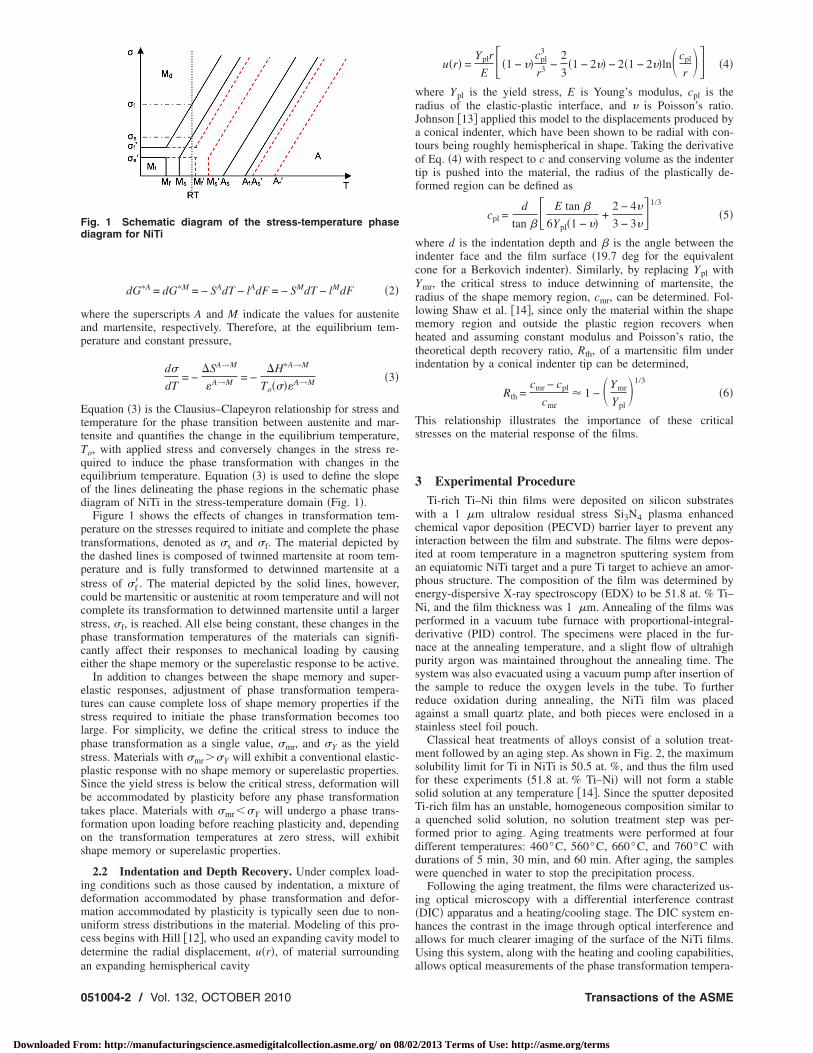
Classical heat treatments of alloys consist of a solution treat-ment followed by an aging step. As shown in Fig. 2, the maximumsolubility limit for Ti in NiTi is 50.5 at. %, and thus the film usedfor these experiments �51.8 at. % Ti–Ni� will not form a stablesolid solution at any temperature �14�. Since the sputter depositedTi-rich film has an unstable, homogeneous composition similar toa quenched solid solution, no solution treatment step was per-formed prior to aging. Aging treatments were performed at fourdifferent temperatures: 460°C, 560°C, 660°C, and 760°C withdurations of 5 min, 30 min, and 60 min. After aging, the sampleswere quenched in water to stop the precipitation process.
Following the aging treatment, the films were characterized us-ing optical microscopy with a differential interference contrast�DIC� apparatus and a heating/cooling stage. The DIC system en-hances the contrast in the image through optical interference andallows for much clearer imaging of the surface of the NiTi films.Using this system, along with the heating and cooling capabilities,
allows optical measurements of the phase transformation tempera-Transactions of the ASME
/2013 Terms of Use: http://asme.org/terms
tt
wrfitfbfist
dmcpatm
mdwbofi�cdfftmicataca
J
Downloaded Fr
ures by observing the disappearance and reappearance of the mar-ensitic surface relief upon changes in temperature.
In situ temperature dependent X-ray diffraction measurementsere also performed on the annealed specimens to determine the
oom temperature phase and transformation temperatures of thelm. By observing the growth and decay of the austenitic peaks in
he XRD spectrum with changes in temperature, the phase trans-ormation temperatures can be identified. The growth of the peaksegins at the austenitic start temperature and ends at the austeniticnish temperature, while decay of the peaks begins at the marten-itic start temperature and ends at the martensitic finish tempera-ure.
The heating and cooling stage for both the in situ temperatureependent optical microscopy and X-ray diffraction measure-ents consisted of a water-cooled Peltier module. Heating and
ooling were achieved using the same device by switching theolarity of the supply voltage. Temperatures were measured usingthermocouple that was placed on the surface of a second, iden-
ical sample situated nearby on the thermoelectric device to mini-ize interference with imaging and diffraction measurements.Nanoindentation was used as a means to determine the shapeemory and mechanical properties of the annealed thin films. A
iamond Berkovich tip was used. Two types of indentation testsere performed on the annealed specimens. For the first type, theasic indentation test, the indentation modulus, and the hardnessf the films are calculated at a specified displacement into thelm. The second type is the continuous stiffness measurementCSM�. By applying a small oscillating load over the basic loadurve, local unloading can be achieved at each increment in in-entation depth, and material properties can be measured as aunction of depth into the surface. CSM measurements were per-ormed to a depth of 1 �m to characterize the full thickness ofhe film. Basic tests were performed to a depth of 100 nm to
inimize substrate effects on the material response. The basicndentations were subsequently imaged using an atomic force mi-roscope to determine their initial depth, Dmax, and measuredgain after being heated above their austenitic finish temperatureso determine the recovered depth, Dr. The recovery ratio, defineds = �Dmax−Dr� /Dmax, represents the level of deformation ac-ommodated by detwinning and phase transformations and is
Fig. 2 NiTi phase diagram. Note nearside of NiTi †20‡.
nalogous to Eq. �6�.
ournal of Manufacturing Science and Engineering
om: http://manufacturingscience.asmedigitalcollection.asme.org/ on 08/02
4 Results and DiscussionAmong the many factors that influence the mechanical and
shape memory properties of NiTi films is the microstructure of thematerial, more specifically, the size and types of precipitates. Ti-rich NiTi has been shown to develop NiTi2 precipitates; however,due to the maximum solubility of Ti in NiTi being only 50.5 at. %,in bulk materials NiTi2 precipitates only form at grain boundaries,which limits their effectiveness in changing the properties of thematerial. Sputter deposition of Ti-rich NiTi thin films, however, isable to create an unstable structure with a homogeneous distribu-tion of Ti no matter what the composition is. The subsequentaging of these films causes precipitates to form within the NiTigrains, which initially form as thin plates or Guinier–Preston �GP�zones at low annealing temperatures and times �10�. These plateprecipitates are coherent with the austenite matrix, and their co-herency strains strengthen the austenite phase. Increases in theannealing temperature or time have been shown to cause the pre-cipitates to become spherical in shape and lose their coherencywith the austenite matrix resulting in a decreased critical stress forslip.
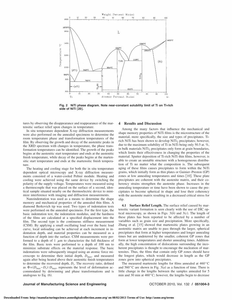
4.1 Surface Relief Length. The surface relief caused by mar-tensitic variant formation is seen clearly with the use of DIC op-tical microscopy, as shown in Figs. 3�b� and 3�c�. The length ofthese plates has been reported to be affected by a number ofvariables such as grain size and precipitation. More specifically,Zhang et al. �15� showed that martensitic plates growing in anaustenitic matrix are unable to pass through the larger, sphericalprecipitates that form at higher temperatures and longer annealingtimes but are undeterred by the smaller, coherent GP zones thatform at lower temperatures and shorter annealing times. Addition-ally, the high concentration of dislocations surrounding the inco-herent precipitates is thought to encourage the nucleation of mar-tensites. Thus, the films that contain only GP zones should havethe longest plates, which would decrease in length as the GPzones grew into spherical precipitates.
The measured martensite lengths for films annealed at 460°Cand 560°C are shown in Fig. 3�a� as a function of time. There islittle change in the lengths between the samples annealed for 5
nstant solubility limit of Ti on Ti-rich
-comin and 30 min at 460°C; however, the lengths begin to decrease
OCTOBER 2010, Vol. 132 / 051004-3
/2013 Terms of Use: http://asme.org/terms
fstetBgsttatowp
ptbbapnccwl
sc4varsesmsmoo
Facab
0
Downloaded Fr
or the 60 min annealing time. The surface relief lengths for theamples annealed at 560°C are still shorter and show a similarrend of decreasing length with annealing time. This behavior isxpected due to the increase in diffusion rate at higher tempera-ures and greater time for diffusion to occur for longer anneals.oth of these relationships have the effect of allowing for greaterrowth of the precipitates from the initial GP zones to largerpherical precipitates. As the spherical precipitates begin to form,he maximum plate length is reduced due to their inability to growhrough those regions. Ishida et al. �16� also showed that there is
transition region between materials containing GP zones andhose with spherical precipitates where a mixture of the two typesf precipitates is observed. This observation qualitatively agreesith our experimental data, which show a gradual decrease inlate length with increasing annealing temperature and time.
While precipitate formation is one factor in determining thelate size, grain size also has an effect on the maximum size dueo the fact that the plates generally do not grow through grainoundaries. This suggests that a decreasing grain size could alsoe the reason for the observed decrease in plate length with timend temperature. However, it was observed that the maximumlate lengths for the films annealed at 460°C and 560°C wereearly identical, suggesting that the grain size of the films is nothanging significantly and is thus not responsible for the observedhange in plate length. The films annealed at higher temperaturesere austenitic even upon cooling to 5°C, and surface relief
ength could not be measured.
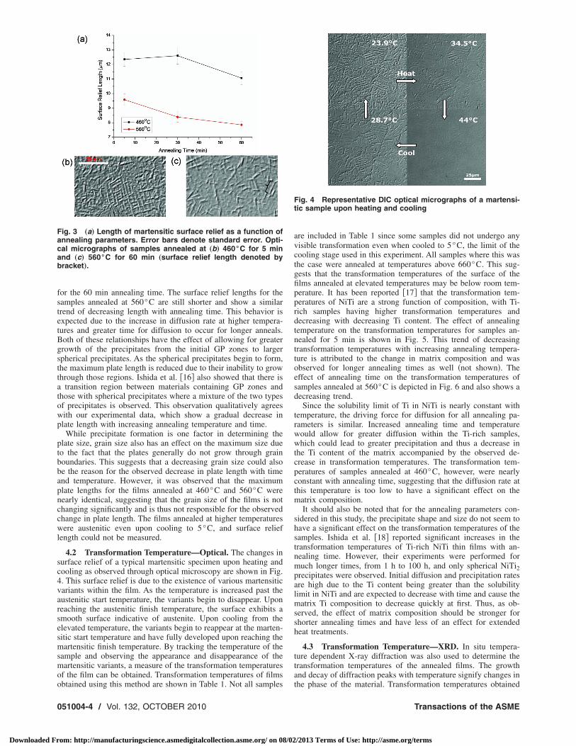
4.2 Transformation Temperature—Optical. The changes inurface relief of a typical martensitic specimen upon heating andooling as observed through optical microscopy are shown in Fig.. This surface relief is due to the existence of various martensiticariants within the film. As the temperature is increased past theustenitic start temperature, the variants begin to disappear. Uponeaching the austenitic finish temperature, the surface exhibits amooth surface indicative of austenite. Upon cooling from thelevated temperature, the variants begin to reappear at the marten-itic start temperature and have fully developed upon reaching theartensitic finish temperature. By tracking the temperature of the
ample and observing the appearance and disappearance of theartensitic variants, a measure of the transformation temperatures
f the film can be obtained. Transformation temperatures of films
ig. 3 „a… Length of martensitic surface relief as a function ofnnealing parameters. Error bars denote standard error. Opti-al micrographs of samples annealed at „b… 460°C for 5 minnd „c… 560°C for 60 min „surface relief length denoted byracket….
btained using this method are shown in Table 1. Not all samples
51004-4 / Vol. 132, OCTOBER 2010
om: http://manufacturingscience.asmedigitalcollection.asme.org/ on 08/02
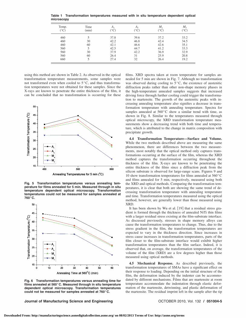
are included in Table 1 since some samples did not undergo anyvisible transformation even when cooled to 5°C, the limit of thecooling stage used in this experiment. All samples where this wasthe case were annealed at temperatures above 660°C. This sug-gests that the transformation temperatures of the surface of thefilms annealed at elevated temperatures may be below room tem-perature. It has been reported �17� that the transformation tem-peratures of NiTi are a strong function of composition, with Ti-rich samples having higher transformation temperatures anddecreasing with decreasing Ti content. The effect of annealingtemperature on the transformation temperatures for samples an-nealed for 5 min is shown in Fig. 5. This trend of decreasingtransformation temperatures with increasing annealing tempera-ture is attributed to the change in matrix composition and wasobserved for longer annealing times as well �not shown�. Theeffect of annealing time on the transformation temperatures ofsamples annealed at 560°C is depicted in Fig. 6 and also shows adecreasing trend.
Since the solubility limit of Ti in NiTi is nearly constant withtemperature, the driving force for diffusion for all annealing pa-rameters is similar. Increased annealing time and temperaturewould allow for greater diffusion within the Ti-rich samples,which could lead to greater precipitation and thus a decrease inthe Ti content of the matrix accompanied by the observed de-crease in transformation temperatures. The transformation tem-peratures of samples annealed at 460°C, however, were nearlyconstant with annealing time, suggesting that the diffusion rate atthis temperature is too low to have a significant effect on thematrix composition.
It should also be noted that for the annealing parameters con-sidered in this study, the precipitate shape and size do not seem tohave a significant effect on the transformation temperatures of thesamples. Ishida et al. �18� reported significant increases in thetransformation temperatures of Ti-rich NiTi thin films with an-nealing time. However, their experiments were performed formuch longer times, from 1 h to 100 h, and only spherical NiTi2precipitates were observed. Initial diffusion and precipitation ratesare high due to the Ti content being greater than the solubilitylimit in NiTi and are expected to decrease with time and cause thematrix Ti composition to decrease quickly at first. Thus, as ob-served, the effect of matrix composition should be stronger forshorter annealing times and have less of an effect for extendedheat treatments.
4.3 Transformation Temperature—XRD. In situ tempera-ture dependent X-ray diffraction was also used to determine thetransformation temperatures of the annealed films. The growthand decay of diffraction peaks with temperature signify changes in
Fig. 4 Representative DIC optical micrographs of a martensi-tic sample upon heating and cooling
the phase of the material. Transformation temperatures obtained
Transactions of the ASME
/2013 Terms of Use: http://asme.org/terms
utntXc
Fptt7
Ffidc
J
Downloaded Fr
sing this method are shown in Table 2. As observed in the opticalransformation temperature measurements, some samples wereot transformed even when cooled to 5°C, and thus transforma-ion temperatures were not obtained for these samples. Since the-rays are known to penetrate the entire thickness of the film, it
an be concluded that no transformation is occurring for these
Table 1 Transformation temperatures measumicroscopy
Temp.�°C�
Time�min�
As�°C�
460 5 37.8460 30 42.2460 60 42.1560 5 42.5560 30 37.9560 60 26.4660 5 27.4
ig. 5 Transformation temperatures versus annealing tem-erature for films annealed for 5 min. Measured through in situemperature dependent optical microscopy. Transformationemperatures could not be measured for samples annealed at60°C.
ig. 6 Transformation temperatures versus annealing time forlms annealed at 560°C. Measured through in situ temperatureependent optical microscopy. Transformation temperatures
ould not be measured for samples annealed at 760°C.ournal of Manufacturing Science and Engineering
om: http://manufacturingscience.asmedigitalcollection.asme.org/ on 08/02
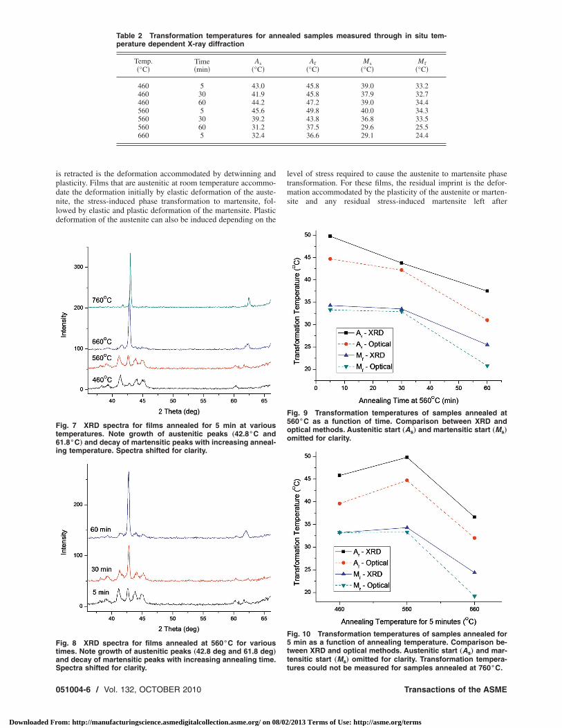
films. XRD spectra taken at room temperature for samples an-nealed for 5 min are shown in Fig. 7. Although no transformationwas observed during cooling to 5°C, the existence of austeniticdiffraction peaks rather than other non-shape memory phases inthe high-temperature annealed samples suggests that increaseddriving force through further cooling could trigger the transforma-tion to martensite. The growth of the austenitic peaks with in-creasing annealing temperature also signifies a decrease in trans-formation temperature with annealing temperature. Spectra forsamples annealed at 560°C show a similar trend with time, asshown in Fig. 8. Similar to the temperatures measured throughoptical microscopy, the XRD transformation temperature mea-surements show a decreasing trend with both time and tempera-ture, which is attributed to the change in matrix composition withprecipitate growth.
4.4 Transformation Temperature—Surface and Volume.While the two methods described above are measuring the samephenomenon, there are differences between the two measure-ments, most notably that the optical method only captures trans-formations occurring at the surface of the film, whereas the XRDmethod captures the transformation occurring throughout thethickness of the film. X-rays are known to be penetrating theentire thickness of the films since a diffraction peak from thesilicon substrate is observed for large-range scans. Figures 9 and10 show transformation temperatures for films annealed at 560°Cand films annealed for 5 min, respectively, measured using boththe XRD and optical methods. Comparing the transformation tem-peratures, it is clear that both are showing the same trend of de-creasing transformation temperature with annealing temperatureand time. Transformation temperatures measured using the opticalmethod, however, are generally lower than those measured usingXRD.
It has been shown by Wu et al. �19� that a residual stress gra-dient is formed through the thickness of annealed NiTi thin filmswith a larger residual stress existing at the film-substrate interface.As discussed previously, stresses in shape memory alloys cancause the transformation temperatures to change. Thus, due to thestress gradient in the film, the transformation temperatures areexpected to vary in the thickness direction. Since increases instress cause increases in transformation temperatures, parts of thefilm closer to the film-substrate interface would exhibit highertransformation temperatures than the film surface. Indeed, it isobserved that, on average, the transformation temperatures of thevolume of the film �XRD� are a few degrees higher than thosemeasured using optical methods.
4.5 Mechanical Response. As described previously, thetransformation temperatures of SMAs have a significant effect ontheir response to loading. Depending on the initial structure of thefilm, the deformation induced by the indenter can be accommo-dated by different mechanisms. Films that are martensite at roomtemperature accommodate the indentation through elastic defor-mation of the martensite, detwinning, and plastic deformation of
with in situ temperature dependent optical
Af�°C�
Ms�°C�
Mf�°C�
39.6 37.2 33.246.8 42.4 34.546.6 42.6 35.144.7 41.2 33.342.2 36.9 32.931 25.9 20.832 26.4 19.2
red
the martensite. The residual imprint left in the sample after the tip
OCTOBER 2010, Vol. 132 / 051004-5
/2013 Terms of Use: http://asme.org/terms
ipdnld
Ft6i
FtaS
0
Downloaded Fr
s retracted is the deformation accommodated by detwinning andlasticity. Films that are austenitic at room temperature accommo-ate the deformation initially by elastic deformation of the auste-ite, the stress-induced phase transformation to martensite, fol-owed by elastic and plastic deformation of the martensite. Plasticeformation of the austenite can also be induced depending on the
Table 2 Transformation temperatures for anperature dependent X-ray diffraction
Temp.�°C�
Time�min�
As�°C�
460 5 43.0460 30 41.9460 60 44.2560 5 45.6560 30 39.2560 60 31.2660 5 32.4
ig. 7 XRD spectra for films annealed for 5 min at variousemperatures. Note growth of austenitic peaks „42.8°C and1.8°C… and decay of martensitic peaks with increasing anneal-
ng temperature. Spectra shifted for clarity.
ig. 8 XRD spectra for films annealed at 560°C for variousimes. Note growth of austenitic peaks „42.8 deg and 61.8 deg…nd decay of martensitic peaks with increasing annealing time.
pectra shifted for clarity.51004-6 / Vol. 132, OCTOBER 2010
om: http://manufacturingscience.asmedigitalcollection.asme.org/ on 08/02
level of stress required to cause the austenite to martensite phasetransformation. For these films, the residual imprint is the defor-mation accommodated by the plasticity of the austenite or marten-site and any residual stress-induced martensite left after
led samples measured through in situ tem-
Af�°C�
Ms�°C�
Mf�°C�
45.8 39.0 33.245.8 37.9 32.747.2 39.0 34.449.8 40.0 34.343.8 36.8 33.537.5 29.6 25.536.6 29.1 24.4
Fig. 9 Transformation temperatures of samples annealed at560°C as a function of time. Comparison between XRD andoptical methods. Austenitic start „As… and martensitic start „Ms…
omitted for clarity.
Fig. 10 Transformation temperatures of samples annealed for5 min as a function of annealing temperature. Comparison be-tween XRD and optical methods. Austenitic start „As… and mar-tensitic start „Ms… omitted for clarity. Transformation tempera-
nea
tures could not be measured for samples annealed at 760°C.
Transactions of the ASME
/2013 Terms of Use: http://asme.org/terms
u
mltde
1Awaahtttcs
at
F1fi
Fid
J
Downloaded Fr
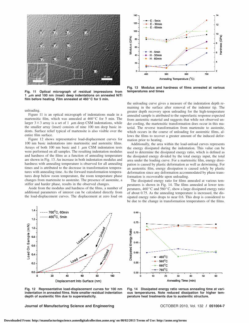
nloading.Figure 11 is an optical micrograph of indentations made in aartensitic film, which was annealed at 460°C for 5 min. The
arger 33 array is a set of 1 �m deep CSM indentations, whilehe smaller array �inset� consists of nine 100 nm deep basic in-ents. Surface relief typical of martensite is also visible over thentire film surface.
Figure 12 shows representative load-displacement curves for00 nm basic indentations into martensitic and austenitic films.rrays of both 100 nm basic and 1 �m CSM indentation testsere performed on all samples. The resulting indentation modulus
nd hardness of the films as a function of annealing temperaturere shown in Fig. 13. An increase in both indentation modulus andardness with annealing temperature is observed for all annealingimes and is attributed to the decrease in transformation tempera-ures with annealing time. As the forward transformation tempera-ures drop below room temperature, the room temperature phasehanges from martensite to austenite. The presence of austenite, atiffer and harder phase, results in the observed changes.
Aside from the modulus and hardness of the films, a number ofdditional parameters of interest can be calculated directly fromhe load-displacement curves. The displacement at zero load on
ig. 11 Optical micrograph of residual impressions from�m and 100 nm „inset… deep indentations on annealed NiTi
lm before heating. Film annealed at 460°C for 5 min.
ig. 12 Representative load-displacement curves for 100 nmndentation in annealed films. Note smaller residual indentation
epth of austenitic film due to superelasticity.ournal of Manufacturing Science and Engineering
om: http://manufacturingscience.asmedigitalcollection.asme.org/ on 08/02
the unloading curve gives a measure of the indentation depth re-maining in the surface after removal of the indenter tip. Thegreater depth recovery upon unloading for the high-temperatureannealed sample is attributed to the superelastic response expectedfrom austenitic material and suggests that while not observed un-der cooling, the martensitic transformation does occur in this ma-terial. The reverse transformation from martensite to austenite,which occurs in the course of unloading for austenitic films, al-lows the films to recover a greater amount of the induced defor-mation prior to heating.
Additionally, the area within the load-unload curves representsthe energy dissipated during the indentation. This value can beused to determine the dissipated energy ratio, which is defined asthe dissipated energy divided by the total energy input, the totalarea under the loading curve. For a martensitic film, energy dissi-pation is caused by plastic deformation as well as detwinning. Foran austenitic film, energy dissipation is caused solely by plasticdeformation since any deformation accommodated by phase trans-formation is recoverable upon unloading.
The dissipated energy ratio for films annealed at various tem-peratures is shown in Fig. 14. The films annealed at lower tem-peratures, 460°C and 560°C, show a large dissipated energy ratioof about 0.75. As the annealing temperature is increased, the dis-sipated energy ratio drops to near 0.6. This drop is considered tobe due to the change in transformation temperatures of the films.
Fig. 13 Modulus and hardness of films annealed at varioustemperatures and times
Fig. 14 Dissipated energy ratio versus annealing time at vari-ous temperatures. Note reduced dissipation for higher tem-
perature heat treatments due to austenitic structure.OCTOBER 2010, Vol. 132 / 051004-7
/2013 Terms of Use: http://asme.org/terms
Spiemasrp
mdadis
dwtii
Fme
Fa
0
Downloaded Fr
ince more energy is recovered in austenitic films due to the su-erelastic effect, they are expected to dissipate less energy duringndentation. However, not all of the samples annealed at 660°Cxhibit the low dissipated energy ratio. The sample annealed for 5in shows a ratio indistinguishable from the films annealed at 460
nd 560°C. This is also the only film annealed above 560°C thathows any martensite at room temperature. The dissipated energyatio is observed to be strongly related to the room temperaturehase of the material and nearly constant for each phase.
4.6 Recoverable Depth. In addition to the material and shapeemory properties derived from the indentation load-
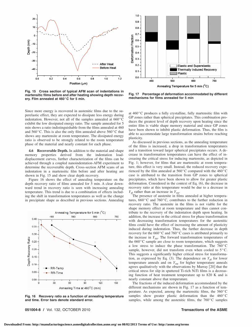
isplacement curves, further characterization of the films can bechieved through a coupled nanoindentation-AFM experiment toetermine the recoverable depth. Cross-section AFM scans of anndentation in a martensitic film before and after heating arehown in Fig. 15 and show clear depth recovery.
Figure 16 shows the effect of annealing temperature on theepth recovery ratio of films annealed for 5 min. A clear down-ard trend in recovery ratio is seen with increasing annealing
emperature. This trend is due to a combination of effects includ-ng the shift in transformation temperatures as well as the changen precipitate shape as described in previous sections. Annealing
ig. 15 Cross section of typical AFM scan of indentations inartensitic films before and after heating showing depth recov-
ry. Film annealed at 460°C for 5 min.
ig. 16 Recovery ratio as a function of annealing temperature
nd time. Error bars denote standard error.51004-8 / Vol. 132, OCTOBER 2010
om: http://manufacturingscience.asmedigitalcollection.asme.org/ on 08/02
at 460°C produces a fully crystalline, fully martensitic film withGP zones rather than spherical precipitates. This combination pro-duces the greatest level of depth recovery upon heating since theentire film is viable shape memory material and since GP zoneshave been shown to inhibit plastic deformation. Thus, the film isable to accommodate large transformation strains before reachingplasticity.
As discussed in previous sections, as the annealing temperatureof the films is increased, a drop in transformation temperaturesand a transition toward larger spherical precipitates occurs. A de-crease in transformation temperatures can have the effect of in-creasing the critical stress for inducing martensite, as depicted inFig. 1; however, for films that are martensitic at room tempera-ture, this effect is very small. Instead, the reduced recovery expe-rienced by the film annealed at 560°C compared with the 460°Ccase is attributed to the transition from GP zones to sphericalprecipitates, which have been shown to allow for greater plasticdeformation. Considered in the context of Eq. �6�, the decrease inrecovery ratio at this temperature would be due to a decrease inYpl rather than an increase in Ymr.
The presence of austenite in films annealed at higher tempera-tures, 660°C and 760°C, contributes to the further reduction inrecovery ratio. The austenite in the films is not viable for theshape memory effect at room temperature and thus cannot con-tribute to the recovery of the indentation depth upon heating. Inaddition, the increase in the critical stress for phase transformationwith decreasing transformation temperatures for the austeniticfilms could have the effect of increasing the amount of plasticityinduced during indentation. Thus, the further decrease in depthrecovery for the 660°C and 760°C cases is attributed primarily tothe increase in Ymr. The forward transformation temperatures ofthe 660°C sample are close to room temperature, which suggestsa low stress to induce the phase transformation. The 760°Csample, however, did not transform even when cooled to 5°C.This suggests a significantly higher critical stress for transforma-tion, as expressed by Eq. �3�. The dependence on Ypl for lowertemperature anneals and on Ymr for higher temperature annealsagrees qualitatively with the observations by Murray �20� that thecritical stress for slip in sputtered Ti-rich NiTi films is a decreas-ing function of heat treatment temperature up to 820 K and isnearly constant above that temperature.
The fractions of the induced deformation accommodated by thedifferent mechanisms are shown in Fig. 17 as a function of tem-perature. As expected, among the martensitic films, the 560°Csamples show greater plastic deformation than the 460°C
Fig. 17 Percentage of deformation accommodated by differentmechanisms for films annealed for 5 min
samples, while among the austenitic films, the 760°C samples
Transactions of the ASME
/2013 Terms of Use: http://asme.org/terms
stctsa
sotptndteirsr
dssbsttds
76dntbid
5
sps
Fb4
J
Downloaded Fr
how greater plastic deformation than the 660°C samples due tohe increase in Ymr. Overall, the thermally induced recovery de-reases with annealing temperature due to the change in the roomemperature phase from martensite to austenite. The elastic anduperelastic deformation increases for the 660°C case due to thedded deformation accommodated by superelasticity.
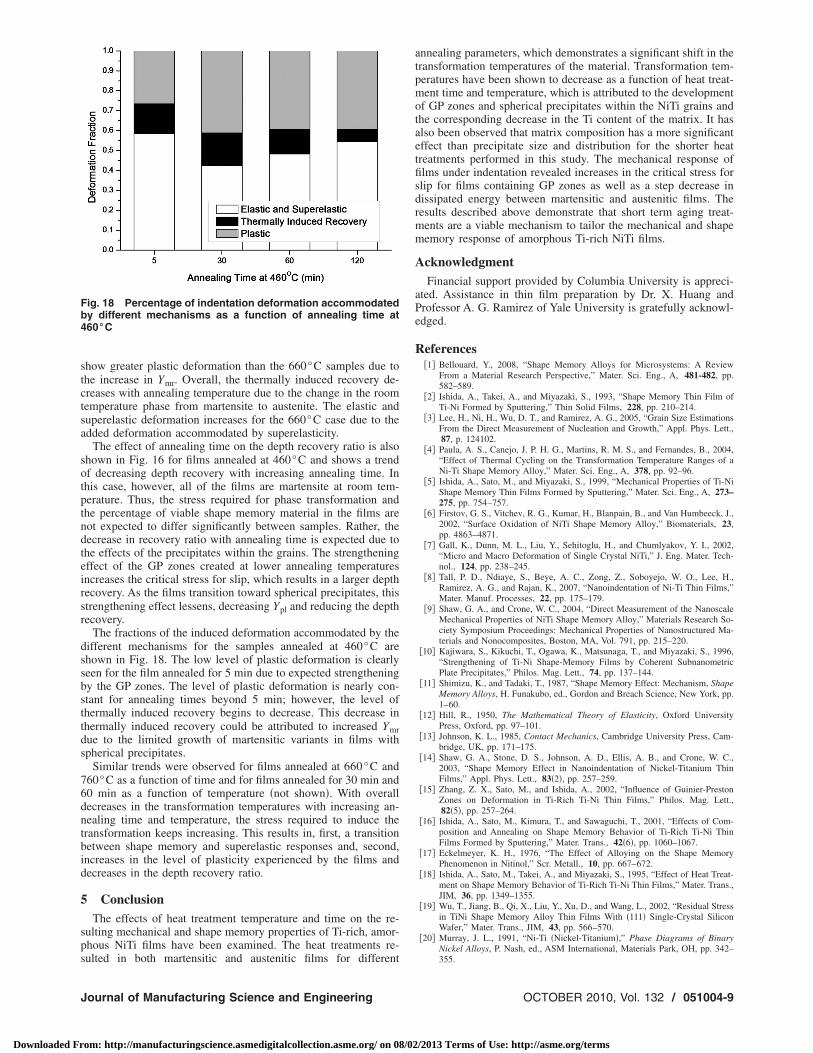
The effect of annealing time on the depth recovery ratio is alsohown in Fig. 16 for films annealed at 460°C and shows a trendf decreasing depth recovery with increasing annealing time. Inhis case, however, all of the films are martensite at room tem-erature. Thus, the stress required for phase transformation andhe percentage of viable shape memory material in the films areot expected to differ significantly between samples. Rather, theecrease in recovery ratio with annealing time is expected due tohe effects of the precipitates within the grains. The strengtheningffect of the GP zones created at lower annealing temperaturesncreases the critical stress for slip, which results in a larger depthecovery. As the films transition toward spherical precipitates, thistrengthening effect lessens, decreasing Ypl and reducing the depthecovery.
The fractions of the induced deformation accommodated by theifferent mechanisms for the samples annealed at 460°C arehown in Fig. 18. The low level of plastic deformation is clearlyeen for the film annealed for 5 min due to expected strengtheningy the GP zones. The level of plastic deformation is nearly con-tant for annealing times beyond 5 min; however, the level ofhermally induced recovery begins to decrease. This decrease inhermally induced recovery could be attributed to increased Ymrue to the limited growth of martensitic variants in films withpherical precipitates.
Similar trends were observed for films annealed at 660°C and60°C as a function of time and for films annealed for 30 min and0 min as a function of temperature �not shown�. With overallecreases in the transformation temperatures with increasing an-ealing time and temperature, the stress required to induce theransformation keeps increasing. This results in, first, a transitionetween shape memory and superelastic responses and, second,ncreases in the level of plasticity experienced by the films andecreases in the depth recovery ratio.
ConclusionThe effects of heat treatment temperature and time on the re-
ulting mechanical and shape memory properties of Ti-rich, amor-hous NiTi films have been examined. The heat treatments re-ulted in both martensitic and austenitic films for different
ig. 18 Percentage of indentation deformation accommodatedy different mechanisms as a function of annealing time at60°C
ournal of Manufacturing Science and Engineering
om: http://manufacturingscience.asmedigitalcollection.asme.org/ on 08/02
annealing parameters, which demonstrates a significant shift in thetransformation temperatures of the material. Transformation tem-peratures have been shown to decrease as a function of heat treat-ment time and temperature, which is attributed to the developmentof GP zones and spherical precipitates within the NiTi grains andthe corresponding decrease in the Ti content of the matrix. It hasalso been observed that matrix composition has a more significanteffect than precipitate size and distribution for the shorter heattreatments performed in this study. The mechanical response offilms under indentation revealed increases in the critical stress forslip for films containing GP zones as well as a step decrease indissipated energy between martensitic and austenitic films. Theresults described above demonstrate that short term aging treat-ments are a viable mechanism to tailor the mechanical and shapememory response of amorphous Ti-rich NiTi films.
AcknowledgmentFinancial support provided by Columbia University is appreci-
ated. Assistance in thin film preparation by Dr. X. Huang andProfessor A. G. Ramirez of Yale University is gratefully acknowl-edged.
References�1� Bellouard, Y., 2008, “Shape Memory Alloys for Microsystems: A Review
From a Material Research Perspective,” Mater. Sci. Eng., A, 481-482, pp.582–589.
�2� Ishida, A., Takei, A., and Miyazaki, S., 1993, “Shape Memory Thin Film ofTi-Ni Formed by Sputtering,” Thin Solid Films, 228, pp. 210–214.
�3� Lee, H., Ni, H., Wu, D. T., and Ramirez, A. G., 2005, “Grain Size EstimationsFrom the Direct Measurement of Nucleation and Growth,” Appl. Phys. Lett.,87, p. 124102.
�4� Paula, A. S., Canejo, J. P. H. G., Martins, R. M. S., and Fernandes, B., 2004,“Effect of Thermal Cycling on the Transformation Temperature Ranges of aNi-Ti Shape Memory Alloy,” Mater. Sci. Eng., A, 378, pp. 92–96.
�5� Ishida, A., Sato, M., and Miyazaki, S., 1999, “Mechanical Properties of Ti-NiShape Memory Thin Films Formed by Sputtering,” Mater. Sci. Eng., A, 273–275, pp. 754–757.
�6� Firstov, G. S., Vitchev, R. G., Kumar, H., Blanpain, B., and Van Humbeeck, J.,2002, “Surface Oxidation of NiTi Shape Memory Alloy,” Biomaterials, 23,pp. 4863–4871.
�7� Gall, K., Dunn, M. L., Liu, Y., Sehitoglu, H., and Chumlyakov, Y. I., 2002,“Micro and Macro Deformation of Single Crystal NiTi,” J. Eng. Mater. Tech-nol., 124, pp. 238–245.
�8� Tall, P. D., Ndiaye, S., Beye, A. C., Zong, Z., Soboyejo, W. O., Lee, H.,Ramirez, A. G., and Rajan, K., 2007, “Nanoindentation of Ni-Ti Thin Films,”Mater. Manuf. Processes, 22, pp. 175–179.
�9� Shaw, G. A., and Crone, W. C., 2004, “Direct Measurement of the NanoscaleMechanical Properties of NiTi Shape Memory Alloy,” Materials Research So-ciety Symposium Proceedings: Mechanical Properties of Nanostructured Ma-terials and Nonocomposites, Boston, MA, Vol. 791, pp. 215–220.
�10� Kajiwara, S., Kikuchi, T., Ogawa, K., Matsunaga, T., and Miyazaki, S., 1996,“Strengthening of Ti-Ni Shape-Memory Films by Coherent SubnanometricPlate Precipitates,” Philos. Mag. Lett., 74, pp. 137–144.
�11� Shimizu, K., and Tadaki, T., 1987, “Shape Memory Effect: Mechanism, ShapeMemory Alloys, H. Funakubo, ed., Gordon and Breach Science, New York, pp.1–60.
�12� Hill, R., 1950, The Mathematical Theory of Elasticity, Oxford UniversityPress, Oxford, pp. 97–101.
�13� Johnson, K. L., 1985, Contact Mechanics, Cambridge University Press, Cam-bridge, UK, pp. 171–175.
�14� Shaw, G. A., Stone, D. S., Johnson, A. D., Ellis, A. B., and Crone, W. C.,2003, “Shape Memory Effect in Nanoindentation of Nickel-Titanium ThinFilms,” Appl. Phys. Lett., 83�2�, pp. 257–259.
�15� Zhang, Z. X., Sato, M., and Ishida, A., 2002, “Influence of Guinier-PrestonZones on Deformation in Ti-Rich Ti-Ni Thin Films,” Philos. Mag. Lett.,82�5�, pp. 257–264.
�16� Ishida, A., Sato, M., Kimura, T., and Sawaguchi, T., 2001, “Effects of Com-position and Annealing on Shape Memory Behavior of Ti-Rich Ti-Ni ThinFilms Formed by Sputtering,” Mater. Trans., 42�6�, pp. 1060–1067.
�17� Eckelmeyer, K. H., 1976, “The Effect of Alloying on the Shape MemoryPhenomenon in Nitinol,” Scr. Metall., 10, pp. 667–672.
�18� Ishida, A., Sato, M., Takei, A., and Miyazaki, S., 1995, “Effect of Heat Treat-ment on Shape Memory Behavior of Ti-Rich Ti-Ni Thin Films,” Mater. Trans.,JIM, 36, pp. 1349–1355.
�19� Wu, T., Jiang, B., Qi, X., Liu, Y., Xu, D., and Wang, L., 2002, “Residual Stressin TiNi Shape Memory Alloy Thin Films With �111� Single-Crystal SiliconWafer,” Mater. Trans., JIM, 43, pp. 566–570.
�20� Murray, J. L., 1991, “Ni-Ti �Nickel-Titanium�,” Phase Diagrams of BinaryNickel Alloys, P. Nash, ed., ASM International, Materials Park, OH, pp. 342–355.
OCTOBER 2010, Vol. 132 / 051004-9
/2013 Terms of Use: http://asme.org/terms