Embed Size (px)
Citation preview
Annals of Physics 324 (2009) 1783–1795
Contents lists available at ScienceDirect
Annals of Physics
journal homepage: www.elsevier .com/ locate /aop
Efficient weakly-radiative wireless energy transfer:An EIT-like approach
Rafif E. Hamam *, Aristeidis Karalis, J.D. Joannopoulos, Marin SoljacicCenter for Materials Science and Engineering and Research Laboratory of Electronics, Massachusetts Institute of Technology,Cambridge, MA 02139, USA
a r t i c l e i n f o a b s t r a c t
Article history:Received 5 December 2008Accepted 15 May 2009Available online 27 May 2009
Keywords:Wireless energy transferCouplingElectromagnetically induced transparency(EIT)Stimulated Raman Adiabatic Passage(STIRAP)Adiabatic followingCoupled mode theoryResonance
0003-4916/$ - see front matter � 2009 Elsevier Indoi:10.1016/j.aop.2009.05.005
* Corresponding author.E-mail address: [email protected] (R.E. Hamam).
Inspired by a quantum interference phenomenon known in theatomic physics community as electromagnetically induced trans-parency (EIT), we propose an efficient weakly radiative wirelessenergy transfer scheme between two identical classical resonantobjects, strongly coupled to an intermediate classical resonantobject of substantially different properties, but with the same res-onance frequency. The transfer mechanism essentially makes useof the adiabatic evolution of an instantaneous (so called ‘‘dark”)eigenstate of the coupled 3-object system. Our analysis is basedon temporal coupled mode theory (CMT), and is general enoughto be valid for various possible sorts of coupling, including the res-onant inductive coupling on which witricity-type wireless energytransfer is based. We show that in certain parameter regimes ofinterest, this scheme can be more efficient, and/or less radiativethan other, more conventional approaches. A concrete example ofwireless energy transfer between capacitively-loaded metallicloops is illustrated at the beginning, as a motivation for the moregeneral case. We also explore the performance of the currently pro-posed EIT-like scheme, in terms of improving efficiency and reduc-ing radiation, as the relevant parameters of the system are varied.
� 2009 Elsevier Inc. All rights reserved.
1. Introduction
The decade has witnessed a considerable interest in energy issues, such as safe generation ofrenewable energy, energy storage and management, etc. In particular, there is a substantial recentinterest [1–5] in enabling efficient and safe wireless energy transfer, motivated by the increased
c. All rights reserved.

1784 R.E. Hamam et al. / Annals of Physics 324 (2009) 1783–1795
involvement of autonomous electronic devices (e.g. laptops, cell phones, household robots) in almostall aspects of our everyday lives, and the need to charge those devices repeatedly. In this respect, wire-less nonradiative energy transfer schemes have been recently proposed [6,7] based on strong couplingbetween electromagnetic resonances. In this work, we explore a somewhat different scheme of effi-cient energy transfer between resonant objects coupled in some general way. Instead of transferringenergy directly between the two resonant objects, an intermediate resonant object will be used tomediate the transfer. The intermediate object is chosen such as to couple very strongly to each ofthe objects involved in the energy transfer (i.e. much more strongly than the other two objects coupleto each other). In practice, enabling such strong coupling will usually come with a price; in typical sit-uations, the mediating object will often be substantially radiative. Yet, surprisingly enough, the pro-posed ‘‘indirect” energy transfer scheme will be shown to be efficient and weakly-radiative bymerely introducing a meticulously chosen time variation of the coupling rates. The inspiration as towhy the particular time variation had to work so well comes from a quantum interference phenom-enon, known in the atomic physics community as electromagnetically induced transparency [8] (EIT).In EIT, 3 atomic states participate. Two of them (which are non-lossy) are coupled to one that has sub-stantial losses. However, by meticulously controlling the mutual couplings between the states, onecan establish a coupled system which is overall non-lossy. This manifests itself in that a medium thatis originally highly opaque to some laser pulse (called ‘‘probe” laser), can be made transparent bysending through it another laser pulse (called ‘‘Stokes” laser), provided that the temporal overlap be-tween the two pulses is properly chosen. A closely related phenomenon known as Stimulated RamanAdiabatic Passage (STIRAP) [9–11] takes place in a similar system; namely, the probe and Stokes lasercan be used to achieve a complete coherent population transfer between two molecular states of themedium. Hence, we refer to the currently proposed scheme as the ‘‘EIT-like” energy transfer scheme.
To set the stage for our proposed indirect energy transfer scheme, we will first consider (in Section 2)one concrete example of wireless energy transfer between two resonant capacitively-loaded conduct-ing-wire loops [6], and show how the indirect EIT-like scheme can be made more efficient and less-radi-ative in this particular system than the direct scheme, by including proper time variations in the couplingrates. In Section 3, we analyze the underlying physical mechanism which turns out to be applicable notjust to ‘‘wireless” energy transfer, but more generally to any sort of energy transfer between resonantobjects. The analysis will be based on temporal coupled mode theory (CMT) [12], which is a valid descrip-tion for well-defined resonances with large quality factors. In Section 4, we study the general case of EIT-like energy transfer, how the transferred and lost energies vary with the rates of coupling and loss, bothwith and without time variation of the coupling rates; we also investigate the range of relevant param-eters in which the radiated energy is substantially reduced by using the EIT-like scheme.
2. An illustrative example of an EIT-like system
We start with a concrete case of wireless energy transfer between two identical resonant conduct-ing loops, labeled by L1 and L3. The loops are capacitively-loaded and couple inductively via their mu-tual inductance. Let rA denote the loops’ radii, NA their numbers of turns, and bA the radii of the wiresmaking the loops. We also denote by D13 the center-to-center separation between the loops. Resonantobjects of this type have two main loss mechanisms: ohmic absorption, and far-field radiation. Usingthe same theoretical method from Ref. [6], we find that for rA ¼ 7 cm, bA ¼ 6 mm, and NA ¼ 15 turns,the quality factors for absorption and radiation are, respectively, Q ðAÞabs � 2pf=CðAÞabs ¼ 3:19� 104 andQ ðAÞrad � 2pf=CðAÞrad ¼ 2:6� 105 at a resonant frequency f ¼ 1:8� 107 Hz (remember that L1 and L3 areidentical and have the same properties). CðAÞabs, CðAÞrad are, respectively, the rates of absorptive and radia-tive loss of L1 and L3, and the rate of coupling between L1 and L3 is denoted by j13. When the loops arein fixed distinct parallel planes separated by D13 ¼ 1:4 m and have their centers on an axis (C) perpen-dicular to their planes, as shown in Fig. 1a, the quality factor for inductive coupling isQj � 2pf=j13 ¼ 1:3� 104, independent of time. This configuration of parallel loops corresponds tothe largest possible coupling rate j13 at the particular separation D13. We denote the amplitude ofthe electric field of the resonant mode of L1 by a1, and that of L3 by a3. As long as all the quality factorsinvolved are large enough, the time evolution of the mode amplitudes a1 and a3 can be modeledaccording to the following temporal CMT equations [12]:

Fig. 1. Wireless energy transfer in an examplary system: (a) (left) Schematic of loops configuration in 2-object direct transfer.(Right) Time evolution of energies in the 2-object direct energy transfer case. (b) (left) Schematic of 3-loops configuration in theconstant-j case. (right) Dynamics of energy transfer for the configuration in (b, left). Note that the total energy transferred E3 istwo times larger than in (a, right), but at the price of the total energy radiated being four times larger. (c) (left) Loopconfiguration at t = 0 in the EIT-like scheme. (Center) Dynamics of energy transfer with EIT-like rotating loops. (Right) Loopconfiguration at t ¼ tEIT . Note that E3 is comparable to (b, right), but the radiated energy is now much smaller: in fact, it iscomparable to (a, right).
R.E. Hamam et al. / Annals of Physics 324 (2009) 1783–1795 1785
da1
dt¼ �ðixþ CAÞ a1 þ ij13a3 ð1Þ
da3
dt¼ �ðixþ CAÞ a3 þ ij13a1 ð2Þ
where x ¼ 2pf is the angular resonance frequency, and CA ¼ CðAÞrad þ CðAÞabs. The mode amplitudes a1ðtÞand a3ðtÞ are normalized such that ja1ðtÞj2 and ja3ðtÞj2 represent, respectively, the energies in L1 andL3 at time t: E1ðtÞ � ja1ðtÞj2 and E3ðtÞ � ja3ðtÞj2. Starting with 100% of the total energy being initiallyin L1 (i.e. ja3ðt ¼ 0Þj2 ¼ 0), we find that the energy transferred to L3 is maximum at timeta ¼ 4774:6ð1=f Þ, and constitutes 29% of the initial total energy, as shown in Fig. 1a. The energies radi-ated EradðtaÞ and absorbed EabsðtaÞ up to time ta constitute, respectively, 7.2% and 58.1% of the initialtotal energy, with 5.8% of the energy remaining in L1. The CMT expressions used for EradðtaÞ andEabsðtaÞ are given by:

1786 R.E. Hamam et al. / Annals of Physics 324 (2009) 1783–1795
EradðtaÞ ¼Z ta
02 CðAÞradja1ðtÞj2 þ 2CðAÞradja3ðtÞj2� �
dt ð3Þ
EabsðtaÞ ¼Z ta
02CðAÞabsja1ðtÞj2 þ 2CðAÞabsja3ðtÞj2� �
dt ð4Þ
In order to improve the efficiency of the energy transfer from the current ’30%, we now considerdifferent ways to boost the energy transferred from L1 to L3 while keeping the distance D13 separatingthem fixed. Since the relative orientations of the two loops are already chosen to yield the maximumj13, we no longer have much flexibility in improving the efficiency of transfer between these givenresonant objects at the same separation D13. So, we introduce an intermediate resonant object thatcouples strongly to both L1 and L3, while having the same resonant frequency as both of them. Forthe sake of illustration in the particular concrete system under consideration, we also take that medi-ator to be a capacitively-loaded conducting-wire loop, and we label it by L2. We place L2 at equal dis-tance ðD12 ¼ D23 ¼ D13=2 ¼ 0:7 mÞ from L1 and L3 such that its axis also lies on the same axis (C), andwe orient it such that its plane is parallel to the planes of L1 and L3. In order for L2 to couple strongly toL1 and L3, its size needs to be substantially larger than the size of L1 and L3. However this increase inthe size of L2 has a considerable drawback in the sense that it is also accompanied by a significant in-crease in the undesired radiated energy. This feature is quite generic for the resonant systems of thistype: stronger coupling can often be enabled by increasing the objects’ size, but it implies strongerradiation from the object in question. Large radiation is often undesirable because it could lead tofar-field interference with other RF systems, and in some systems also because of safety concerns.For rB ¼ 70 cm, bB ¼ 1:5 cm, and NB ¼ 1 turn, we get Q ðBÞabs � 2pf=CðBÞabs ¼ 7706, Q ðBÞrad � 2pf=CðBÞrad ¼ 400,and Qj12
� 2pf=j12 ¼ Qj23¼ 180 at f ¼ 1:8� 107 Hz. A schematic diagram of the 3-loops configura-
tion is depicted in Fig. 1b. If we denote the amplitude of the E-field of the resonance mode in L2 bya2, then the CMT equations can be written as:
da1
dt¼ �ðixþ CAÞa1 þ ij12a2 ð5Þ
da2
dt¼ �ðixþ CBÞa2 þ ij12a1 þ ij23a3 ð6Þ
da3
dt¼ �ðixþ CAÞa3 þ ij23a2 ð7Þ
Note that since the coupling rates j12 and j23 are ’70 times larger than j13, we can ignore the directcoupling between L1 and L3, and focus only on the indirect energy transfer through the intermediateloop L2. If initially all the energy is placed in L1, i.e. if E2ðt ¼ 0Þ � ja2ðt ¼ 0Þj2 ¼ 0 andE3ðt ¼ 0Þ � ja3ðt ¼ 0Þj2 ¼ 0, then the optimum in energy transferred to L3 occurs at a timetb ¼ 129:2ð1=f Þ, and is equal to E3ðtbÞ ¼ 61:50%. The energy radiated up to tb is EradðtbÞ ¼ 31:1%, whilethe energy absorbed is EabsðtbÞ ¼ 3:3%, and 4.1% of the initial energy is left in L1. Thus while the energytransferred, now indirectly, from L1 to L3 has increased by a factor of 2 relative to the 2-loops directtransfer case, the energy radiated has undesirably increased by a significant factor of 4. Also note thatthe transfer time in the 3-loops case is now ’35 times shorter than in the 2-loops direct transfer be-cause of the stronger coupling rate. The dynamics of the energy transfer in the 3-loops case is shown inFig. 1b, where the expressions used for EradðtbÞ and EabsðtbÞ are given by:
EradðtbÞ ¼Z tb
02CA
radja1ðtÞj2 þ 2CBradja2ðtÞj2 þ 2CA
radja3ðtÞj2� �
dt ð8Þ
EabsðtbÞ ¼Z tb
02CA
absja1ðtÞj2 þ 2CBabsja2ðtÞj2 þ 2CA
absja3ðtÞj2� �
dt ð9Þ
Thus the switch from 2-loops direct transfer to 3-loops indirect transfer had an expected significantimprovement in efficiency, but it came with the undesirable effect of increased radiated energy. Let usnow consider some modifications to the 3-loops indirect transfer scheme, aiming to reduce the totalradiated energy back to its reasonable value in the 2-loops direct transfer case, while maintaining thetotal energy transfer at a level comparable to Fig. 1b. As shown in Fig. 1c, we will keep the orientationof L2 fixed, and start initially (t=0) with L1 perpendicular to L2 and L3 parallel to L2, then uniformly ro-

R.E. Hamam et al. / Annals of Physics 324 (2009) 1783–1795 1787
tate L1 and L3, at the same rates, until finally, at ðt ¼ tEITÞ, L1 becomes parallel to L2 and L3 perpendic-ular to it, where we stop the transfer process. This process can be modeled by the following time var-iation in the coupling rates:
j12ðtÞ ¼ j sin pt=2tEITð Þ ð10Þj23ðtÞ ¼ j cos pt=2tEITð Þ ð11Þ
for 0 < t < tEIT , and Qj ¼ 180:1 as before. By using the same CMT analysis as in Eqs. (5)–(7), we find, inFig. 1c, that for tEIT ¼ 1989:4ð1=f Þ, an optimum transfer of 61.2% can be achieved at tc ¼ 1;798:5ð1=f Þ,with only 8.2% of the initial energy being radiated, 28.6% absorbed, and 2% left in L1. This is quiteremarkable: by simply rotating the loops during the transfer, the energy radiated has dropped by afactor of 4, while keeping the same 61% level of the energy transferred, although the instantaneouscoupling rates are now smaller than j. This considerable decrease in radiation is on first sight quitecounterintuitive, because the intermediate resonator L2, which mediates all the energy transfer, ishighly radiative (’650 times more radiative than L1 and L3), and there is much more time to radiate,since the whole process lasts 14 times longer than in Fig. 1b.
A clue to the physical mechanism behind this surprising result can be obtained by observing the dif-ferences between the green curves in Fig. 1b and c. Unlike the case of constant coupling rates, depicted inFig. 1b, where the amount of energy ultimately transferred to L3 goes first through the intermediate loopL2, in the case of time-varying coupling rates, shown in Fig. 1c, there is almost little or no energy in L2 at alltimes during the transfer. In other words, the energy is transferred quite efficiently from L1 to L3, med-iated by L2 without ever being in the highly radiative intermediate loop L2. (Note that direct transfer fromL1 to L3 is identically zero here since L1 is always perpendicular to L3, so all the energy transfer is indeedmediated through L2.) This surprising phenomenon is actually quite similar to the well-known electro-magnetically induced transparency [8] (EIT), which enables complete population transfer between twoquantum states through a third lossy state, coupled to each of the other two states.
3. Physical mechanism behind EIT-like energy transfer scheme
We note that the mechanism explored in the previous section is not restricted to wireless energytransfer between inductively coupled loops, but its scope extends beyond, to the general case of en-ergy transfer between resonant objects (henceforth denoted by Ri) coupled in some general way.So, all the rest of this article falls in this general context, and the only constraints for the EIT-likescheme are that the three resonant objects have the same resonance angular frequency, which we de-note by xo, that all quality factors be large enough for CMT to be valid, and that the initial and finalresonant objects have the same loss rate CA. R1 and R3 will be assumed to have negligible mutual inter-actions with each other, while each of them can be strongly coupled to R2. However, as is often thecase in practice of wireless power transfer [6], R2’s strong coupling with other objects will be assumedto be accompanied with its inferior loss properties compared to R1 and R3, usually in terms of substan-tially larger radiation losses. To analyze the problem in detail, we start by rewriting the CMT Eqs. (5)–(7) in matrix form, and then diagonalizing the resulting time evolution operator bCðtÞ.
ddt
a1
a2
a3
0B@1CA ¼ �ðixo þ CAÞ ij12 0
ij12 �ðixo þ CBÞ ij23
0 ij23 �ðixo þ CAÞ
0B@1CA a1
a2
a3
0B@1CA � bCðtÞ a1
a2
a3
0B@1CA ð12Þ
In the special case where the coupling rates j12 and j23 are constant and equal, Eq. (12) admits a sim-ple analytical solution, presented in the appendix. In the more general case of time dependent and un-equal coupling rates j12ðtÞ and j23ðtÞ, the CMT operator bCðtÞ has an interesting feature which resultsfrom the fact that one of its eigenstates, ~V1, with complex eigenvalue k1 ¼ �ðixo þ CAÞ, has the form
~V1 ¼ e�ixot�CAt
�j23ffiffiffiffiffiffiffiffiffiffiffiffiffiffiffiffiffiffiffiffiffiðj12Þ2þðj23Þ2p
0j12ffiffiffiffiffiffiffiffiffiffiffiffiffiffiffiffiffiffiffiffiffi
ðj12Þ2þðj23Þ2p
0BBB@1CCCA ð13Þ

1788 R.E. Hamam et al. / Annals of Physics 324 (2009) 1783–1795
This eigenstate ~V1 is the most essential building block of our proposed efficient weakly-radiative en-ergy transfer scheme, because it has no energy at all in the intermediate (lossy) resonator R2, i.e.a2ðtÞ ¼ 0 8 t whenever the 3-object system is in state ~V1. In fact if CA ! 0, then the EIT-like energytransfer scheme can be made completely nonradiative, no matter how large is the radiative rateCB
rad, as shown in Fig. 2. Moreover, if the 3-object system is in state ~V1, then j12 ¼ 0 corresponds toall the system’s energy being in R1, while j23 ¼ 0 corresponds to all the system’s energy being inR3. So, the important considerations necessary to achieve efficient weakly radiative energy transfer,consist of preparing the system initially in state ~V1. Thus, if at t ¼ 0 all the energy is in R1, then oneshould have j12ðt ¼ 0Þ ¼ 0 and j23ðt ¼ 0Þ – 0. In the loops’ case where coupling is performed throughinduction, these values for j12 and j23 correspond to exactly the same configuration that we had con-sidered in Fig. 1c, namely starting with L1 ? L2 and L3 k L2. In order for the total energy of the systemto end up in R3, we should have j12ðt ¼ tEITÞ– 0 and j23ðt ¼ tEITÞ ¼ 0. This ensures that the initial andfinal states of the 3-object system are parallel to ~V1. However, a second important consideration is tokeep the 3-object system at all times in ~V1ðtÞ, even as j12ðtÞ and j23ðtÞ are varied in time. This is cru-cial in order to prevent the system’s energy from getting into the intermediate object R2, which may behighly radiative as in the example of Fig. 1, and requires changing j12ðtÞ and j23ðtÞ slowly enough soas to make the entire 3-object system adiabatically follow the time evolution of ~V1ðtÞ. The criterion foradiabatic following can be expressed, in analogy to the population transfer case[9], as
Fig. 2.cosðpt=
~V2;3jd~V1
dt
* +����������� k2;3 � k1
�� �� ð14Þ
where ~V2 and ~V3 are the remaining two eigenstates of bCðtÞ, with corresponding eigenvalues k2 and k3.In principle, one would think of making the transfer time tEIT as long as possible to ensure adiabaticity.However there is a limitation on how slow the transfer process can optimally be, imposed by thelosses in R1 and R3. Such a limitation may not be a strong concern in a typical atomic EIT case, becausethe initial and final states there can be chosen to be non-lossy ground states. However, in our case,losses in R1 and R3 are not avoidable, and can be detrimental to the energy transfer process wheneverthe transfer time tEIT is not less than 1=CA. This is because, even if the 3-object system is carefully keptin ~V1 at all times, the total energy of the system will decrease from its initial value as a consequence oflosses in R1 and R3. Thus the duration of the transfer should be a compromise between these two lim-its: the desire to keep tEIT long enough to ensure near-adiabaticity, but short enough not to suffer fromlosses in R1 and R3.
We can now also see in the EIT framework why is it that we got a considerable amount of radiatedenergy when the inductive coupling rates of the loops were kept constant in time, i.e. in constant-jcase, like in Fig. 1b. The reason is that, when j12 ¼ j23 ¼const, the energies in R1 and R3 will alwaysbe equal to each other if the 3-object system is to stay in ~V1. So one cannot transfer energy from R1 toR3 by keeping the system purely in state ~V1; note that even the initial state of the system, in which all
0 10000 20000 30000 40000time 1 f
10
20
30
40
50
60
70
80
90
100
Ene
rgy
%
E3
E2
E1
Energy transfer with time-varying coupling rates, for CA ¼ 0, j=CB ¼ 10;j12 ¼ j sinðpt=ð2tEIT ÞÞ, and j23 ¼ jð2tEIT ÞÞ.

R.E. Hamam et al. / Annals of Physics 324 (2009) 1783–1795 1789
the energy is in R1, is not in ~V1, and has nonzero components along the eigenstates ~V2 and ~V3 whichimplies a finite energy in R2, and consequently result in an increased radiation, especially if CB
rad � CArad
as in our concrete example.Although the analysis presented above, in terms of the adiabatic following of the eigenstate ~V1,
clarifies why the EIT-like transfer scheme is weakly radiative, this explanation still seems to be puz-zling and somewhat paradoxical. The origin of the paradox stems from the fact that, in the EIT-likeapproach, there is no energy at all in the mediator R2. That is to say, energy is efficiently transferredthrough the intermediate resonator R2 without ever being in it. This apparent contradiction can be re-solved by looking at the detailed contributions to the time-rate of change of the energy E2 in R2. As weshow it in more details in the appendix, the EIT-like approach ensures that the energy leaves R2 (to R3)as soon as it reaches R2 (from R1).
4. Under which conditions is EIT-like approach beneficial?
In the abstract case of energy transfer from R1 to R3, where no constraints are imposed on the rel-ative magnitude of j; CA
rad; CBrad; CA
abs and CBabs, there is no reason to think that the EIT-like transfer is
always better than the constant-j one, in terms of the transferred and radiated energies. In fact, therecould exist some range of the parameters ðj; CA
rad; CBrad; CA
abs; CBabsÞ, for which the energy radiated in
the constant-j transfer case is less than that radiated in the EIT-like case. For this reason, we inves-tigate both the EIT-like and constant-j transfer schemes, as we vary all the crucial parameters ofthe system. The percentage of energies transferred and lost (radiated + absorbed) depends only onthe relative values of j; CA and CB. Here, CA ¼ CA
rad þ CAabs, and CB ¼ CB
rad þ CBabs. Hence we first calcu-
late and visualize the dependence of these energies on the relevant parameters j=CB and CB=CA, in thecontour plots shown in Fig. 3.
The way the contour plots are calculated is as follows. For each value of (j=CB;CB=CA) in the adi-abatic case, where j12ðtÞ and j23ðtÞ are given by Eqs. (10) and (11), one tries a range of values of tEIT .For each tEIT , the maximum energy transferred E3ð%Þ over 0 < t < tEIT , denoted by maxðE3; tEITÞ, is cal-culated together with the total energy lost at that maximum transfer. Next the maximum ofmaxðE3; tEITÞ over all values of tEIT is selected and plotted as a single point on the contour plot inFig. 3a. We refer to this point as the optimum energy transfer ð%Þ in the EIT-like case for the particular(j=CB;CB=CA) under consideration. We also plot in Fig. 3d the corresponding value of the total energylost (%) at the optimum of E3. We repeat these calculations for all pairs (j=CB;CB=CA) shown in thecontour plots. In the constant-j transfer case, for each (j=CB;CB=CA), the time evolution of E3ð%Þand Elost are calculated for 0 < t < 2=j, and optimum transfer, shown in Fig. 3b, refers to the maximumof E3ðtÞ over 0 < t < 2=j. The corresponding total energy lost at optimum constant-j transfer is shownin Fig. 3e. Now that we calculated the energies of interest as functions of (j=CB;CB=CA), we look forranges of the relevant parameters in which the EIT-like transfer has advantages over the constant-jone. So, we plot the ratio of ðE3ÞEIT�like=ðE3Þconstant�j in Fig. 3c, and ðElostÞconstant�j=ðElostÞEIT�like in Fig. 3f.We find that, for CB=CA > 50, the optimum energy transferred in the adiabatic case exceeds that inthe constant-j case, and the improvement factor can be larger than 2. From Fig. 3f, one sees thatthe EIT-like scheme can reduce the total energy lost by a factor of 3 compared to the constant-jscheme, also in the range CB=CA > 50.
Although one is usually interested in reducing the total energy lost (radiated + absorbed) asmuch as possible in order to make the transfer more efficient, the undersirable nature of the radi-ated energy makes it often important to consider reducing the energy radiated, instead of onlyconsidering the total energy lost. For this purpose, we calculate the energy radiated at optimumtransfer in both the EIT-like and constant-j schemes, and compare them. The relevant parametersin this case are j=CB; CB=CA; CA
rad=CA, and CBrad=CB. The problem is more complex because the
parameter space is now 4-dimensional. So we focus on those particular cross sections that canbest reveal the most important differences between the two schemes. From Fig. 3c and f, onecan guess that the best improvement in both E3 and Elost occurs for CB=CA P 500. Moreover,knowing that it is the intermediate object R2 that makes the main difference between the EIT-likeand constant-j schemes, being ‘‘energy-empty” in the EIT-like case and ‘‘energy-full” in the con-stant-j one, we first look at the special situation where CA
rad ¼ 0. In Fig. 4a and b, we show con-
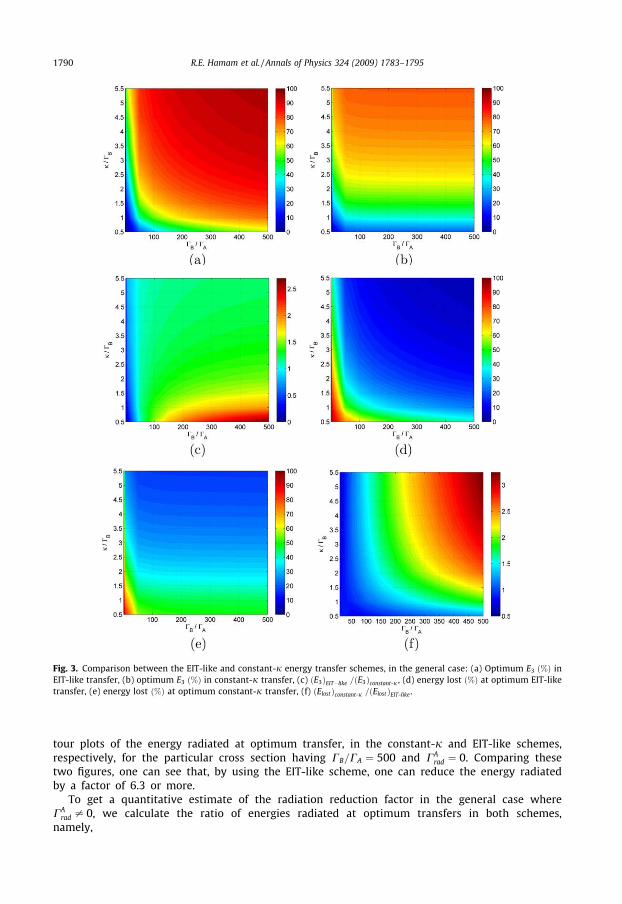
Fig. 3. Comparison between the EIT-like and constant-j energy transfer schemes, in the general case: (a) Optimum E3 ð%Þ inEIT-like transfer, (b) optimum E3 ð%Þ in constant-j transfer, (c) ðE3ÞEIT�like =ðE3Þconstant-j , (d) energy lost ð%Þ at optimum EIT-liketransfer, (e) energy lost ð%Þ at optimum constant-j transfer, (f) ðElostÞconstant-j =ðElostÞEIT-like .
1790 R.E. Hamam et al. / Annals of Physics 324 (2009) 1783–1795
tour plots of the energy radiated at optimum transfer, in the constant-j and EIT-like schemes,respectively, for the particular cross section having CB=CA ¼ 500 and CA
rad ¼ 0. Comparing thesetwo figures, one can see that, by using the EIT-like scheme, one can reduce the energy radiatedby a factor of 6.3 or more.
To get a quantitative estimate of the radiation reduction factor in the general case whereCA
rad – 0, we calculate the ratio of energies radiated at optimum transfers in both schemes,namely,

Fig. 4. Comparison between radiated energies in the EIT-like and constant-j energy transfer schemes: (a) Eradð%Þ in theconstant-j scheme for CB=CA ¼ 500 and CA
rad ¼ 0, (b) Eradð%Þ in the EIT-like scheme for CB=CA ¼ 500 and CArad ¼ 0, (c)
ðEradÞconstant-j =ðEradÞEIT-like for CB=CA ¼ 50, (d) ðEradÞconstant-j =ðEradÞEIT-like for CB=CA ¼ 500, (e) ½ðEradÞconstant-j=ðEradÞEIT�like� as a functionof j=CB and CB=CA , for CA
rad ¼ 0.
R.E. Hamam et al. / Annals of Physics 324 (2009) 1783–1795 1791
ðEradÞconstant-jðEradÞEIT-like
¼
R tconstant-jopt
0CB
rad
CAradjaconstant-j
2 ðtÞj2 þ jaconstant-j1 ðtÞj2 þ jaconstant-j
3 ðtÞj2� �� �
dt
R tEIT-likeopt
0CB
rad
CAradjaEIT-like
2 ðtÞj2 þ jaEIT-likeðtÞj2 þ jaEIT-like3 ðtÞj2
� �� �dt
ð15Þ
which depends only on CBrad=C
Arad, the time-dependent mode amplitudes, and the optimum transfer
times in both schemes. The latter two quantities are completely determined by j=CB, and CB=CA.Hence the only parameters relevant to the calculations of the ratio of radiated energies areCB
rad=CArad, j=CB, and CB=CA, thus reducing the dimensionality of the investigated parameter space from
4 down to 3. For convenience, we multiply the first relevant parameter CBrad=C
Arad by CA=CB, which be-
comes ðCBrad=CBÞ=ðCA
rad=CAÞ, i.e. the ratio of quantities that specify what percentage of each object’s lossis radiated. Next, we calculate the ratio of energies radiated as a function of ðCB
rad=CBÞ=ðCArad=CAÞ and
j=CB, in the two special cases CB=CA ¼ 50, and CB=CA ¼ 500, and we plot them in Fig. 4c and d, respec-tively. We also show, in Fig. 4e, the dependence of ðEradÞconstant-j =ðEradÞEIT-like on j=CB and CB=CA, for thespecial case CA
rad ¼ 0. As can be seen from Fig. 4c and d, the EIT-like scheme is less radiative than theconstant-j scheme whenever (CB
rad=CB) is larger than (CArad=CA), and the radiation reduction ratio in-
creases as CB=CA and j=CB are increased (see Fig. 4e).
5. Conclusion
In conclusion, we proposed an efficient weakly radiative energy transfer scheme between twoidentical resonant objects, based on an EIT-like transfer of the energy through a mediating resonantobject with the same resonant frequency. We analyzed the problem using CMT, and pointed out thatthe fundamental principle underlying our energy transfer scheme is similar to the known EIT process[9] in which there is complete population transfer between two quantum states. We also explored

1792 R.E. Hamam et al. / Annals of Physics 324 (2009) 1783–1795
how the EIT-like scheme compares to the constant-j one, as the relevant parameters of the system arevaried. We motivated all this, initially, by specializing to the problem of witricity-like wireless energytransfer between inductively-coupled metallic loops. However, our proposed scheme, not being re-stricted to the special type of resonant inductive coupling, is not bound only to wireless energy trans-fer, and could potentially find applications in various other unexplored types of coupling betweengeneral resonant objects. In fact, in this context, the work presented here generalizes the concept ofEIT, previously known as a quantum mechanical phenomenon that exists in microscopic systems, toa more general energy transfer phenomenon, between arbitrary classical resonant objects. We focusedon the particular example of electromagnetic resonators, but the nature of the resonators and theircoupling mechanisms could as well be quite different, e.g. acoustic, mechanical, etc. Since all these res-onant phenomena could be modeled with nearly identical CMT equations, the same behavior wouldoccur.
Acknowledgments
Finally, we acknowledge Dr. Peter Bermel and Prof. Steven G. Johnson for their help. This work wassupported in part by the Materials Research Science and Engineering Center Program of the NationalScience Foundation under award DMR 02-13282, the Army Research Office through the Institute forSoldier Nanotechnologies contract W911NF-07-D-0004, DARPA via the U.S. Army Research Office un-der contract W911NF-07-D-0004, the U.S. Department of Energy under award number DE-FG02-99ER45778, and by a grant from 3M. We also acknowledge support of the Buchsbaum award.
Appendix A
A.1. Analytical solution of the 3-object system in the constant-j case
The CMT equations Eq. (12) admit a simple analytical solution in the special case where the cou-pling rates j12ðtÞ and j23ðtÞ are independent of time and equal to each other, namely whenj12 ¼ j23 ¼ constant independent of time. After making the following set of substitutions
R � 1U� CA þ CB
2ffiffiffi2p
jð16Þ
D � CB � CA
2ffiffiffi2p
jð17Þ
T �ffiffiffi2p
jt ð18Þ
we obtain the expressions below for the time-varying amplitudes
a1ðTÞ ¼12
e�ixte�RT DffiffiffiffiffiffiffiffiffiffiffiffiffiffiffiD2 � 1
p sinhffiffiffiffiffiffiffiffiffiffiffiffiffiffiffiD2 � 1
pT
� �þ cosh
ffiffiffiffiffiffiffiffiffiffiffiffiffiffiffiD2 � 1
pT
� �þ e�DT
" #ð19Þ
a2ðTÞ ¼ ie�ixte�RT 1ffiffiffiffiffiffiffiffiffiffiffiffiffiffiffiD2 � 1
p sinhffiffiffiffiffiffiffiffiffiffiffiffiffiffiffiD2 � 1
pT
� �ð20Þ
a3ðTÞ ¼12
e�ixte�RT DffiffiffiffiffiffiffiffiffiffiffiffiffiffiffiD2 � 1
p sinhffiffiffiffiffiffiffiffiffiffiffiffiffiffiffiD2 � 1
pT
� �þ cosh
ffiffiffiffiffiffiffiffiffiffiffiffiffiffiffiD2 � 1
pT
� �� e�DT
" #ð21Þ
The time topt at which the energy transferred to R3 is optimum, can be obtained by setting the timederivative of the energy ja3ðTÞj2 in R3 to zero, and is therefore a solution to the following equation
RDffiffiffiffiffiffiffiffiffiffiffiffiffiffiffi
D2 � 1p sinh
ffiffiffiffiffiffiffiffiffiffiffiffiffiffiffiD2 � 1
pT
� �þ cosh
ffiffiffiffiffiffiffiffiffiffiffiffiffiffiffiD2 � 1
pT
� �" #�
D
ffiffiffiffiffiffiffiffiffiffiffiffiffiffiffiD2 � 1
pD
sinhffiffiffiffiffiffiffiffiffiffiffiffiffiffiffiD2 � 1
pT
� �þ cosh
ffiffiffiffiffiffiffiffiffiffiffiffiffiffiffiD2 � 1
pT
� �" #¼ ðR� DÞeDT ð22Þ

R.E. Hamam et al. / Annals of Physics 324 (2009) 1783–1795 1793
In general, this equation may not have an obvious analytical solution, but it does admit a simplesolution in the two special cases that we will consider below.
In the first special case, we set D ¼ 0, and thus we have CA ¼ CB ¼ C and R ¼ 1U ¼ Cffiffi
2p
j. In this case,
Topt �ffiffiffi2p
jtopt becomes
Topt ¼ 2 tan�1 1R
� ¼ 2 tan�1U ð23Þ
and the efficiency of the 3-object system becomes
g � ja3ðToptÞj2
ja1ð0Þj2¼ U2
1þ U2 exp�2tan�1U
U
� " #2
ð24Þ
which is just the square of the efficiency of the two-object system [6]. Therefore, when all objects arethe same, the efficiency of the 3-object system at optimum is equal to the square of the efficiency ofthe 2-object system, and hence is smaller than it.
In the second special case, we set D ¼ R ¼ 1U ¼
CB
2ffiffi2p
j, that is to say we set CA ¼ 0. The analytical
expressions for Topt and g become, respectively
Topt ¼pUffiffiffiffiffiffiffiffiffiU2�1p ; U > 1
1; U 6 1
(ð25Þ
g ¼14 1þ exp �pffiffiffiffiffiffiffiffiffi
U2�1p� �2
; U > 1
14 ; U 6 1
8><>: ð26Þ
Therefore, the optimum efficiency in this case, is larger when j > CB2ffiffi2p .
A.2. Resolution of apparent paradox in EIT-like scheme
As we said earlier in the text, the explanation of the EIT-like scheme in terms of the adiabatic fol-lowing of the eigenstate ~V1, seems to be puzzling and somewhat paradoxical. The reason is that energyis efficiently transferred through the intermediate resonator R2 without ever being in it. This apparentcontradiction can be resolved by looking at the detailed contributions to the time-rate of change of theenergy E2 in R2. Since the energy in R2 at time t is E2ðtÞ ¼ ja2ðtÞj2, one can use the CMT Eq. (12) andcalculate the power dE2ðtÞ=dt through R2, to obtain
dja2j2
dt¼ �2CBja2j2 � 2j12Imða�2a1Þ þ 2j23Imða�3a2Þ: ð27Þ
The first term on the right-hand side of this equation corresponds to the total power lost in R2. Thesecond term can be identified with the time-rate P12ðtÞ of energy transfer from R1 to R2, namelyP12ðtÞ ¼ �2j12ðtÞImða�2ðtÞa1ðtÞÞ. Similarly, the third term can be identified with the time-rate P23ðtÞof energy transfer from R2 to R3: P23ðtÞ ¼ 2j23ðtÞImða�3ðtÞa2ðtÞÞ. Note that because P12ðtÞ representsthe rate at which energy gets into R2 (coming from R1), this term will be positive. Similarly, becauseP23ðtÞ is the rate at which energy gets out of R2 (going to R3), this term will be negative. For simplicity,we will focus on the case where CA ¼ CB ¼ 0, and take the time variation of the coupling rates to begiven by Eqs. (10) and (11). In this case, the total energy in the 3-object system is conserved, and thechange in the energy E2 can arise only from the exchange of energy between R1 and R2, and between R2
and R3. In this special case, the rate of change of E2, which equals the sum P12 þ P23, is oscillatory intime with amplitude Asum. It turns out that as the transfer time tEIT gets longer, the peak amplitudeAsum of the sum P12 þ P23 approaches zero. This means that at the moment when energy reaches R2
from R1, it leaves R2 immediately to R3. Therefore, dE2ðtÞ=dt is almost zero 8 t, and the energy in R2
remains approximately equal to its initial value of zero throughout the EIT-like transfer, despite thefact that all the energy initially in R1 goes through R2 as it gets transferred to R3. To illustrate this point,we consider again the case CA ¼ CB ¼ 0, and choose the coupling rate j such that Qj ¼ 1000. In Fig. 5a,we plot the powers P12, P23 and their sum as functions of time when the duration of the transfer is

0 1000 2000 3000 4000 5000 6000Time 1 f
5
4
3
2
1
0
1
2
3
4
5
Pow
erP12 P23
P23
P12
0 5000 10000 15000 20000 25000 30000Time 1 f
1
0.8
0.6
0.4
0.2
0
0.2
0.4
0.6
0.8
1
Pow
er
P12 P23
P23
P12
0 0.4 0.8 1.2 1.6 2 2.4 2.8 3.2x 10⁴
0
0.2
0.4
0.6
0.8
1
tEIT (1/f)
Max
(P12
+P23
) / M
ax(P
12−P
23)
Fig. 5. (a) P12, P23 and P12 þ P23 as functions of time for CA ¼ CB ¼ 0, Qj ¼ 1000, and tEIT ¼ 6366:2ð1=f Þ. (b) Same plot as in (a)but with tEIT five times longer. (c) Max(P12 þ P23)/max(P12 � P23Þ versus tEIT for CA ¼ CB ¼ 0 and Qj ¼ 1000.
1794 R.E. Hamam et al. / Annals of Physics 324 (2009) 1783–1795

R.E. Hamam et al. / Annals of Physics 324 (2009) 1783–1795 1795
tEIT ¼ 6366:2ð1=f Þ. In Fig. 5b, we repeat the same plots but now with a transfer time five times longer.As can be seen by comparing Fig. 5a and b, we find that the relative amplitude Asum, compared to char-acteristic magnitudes of P12 and P23, has dramatically decreased. To get a quantitative estimate of thisdecrease in the amplitude of P12 þ P23, we show in Fig. 5c, the ratio of Asum over the maximum ofP12 � P23 as a function of tEIT . We find that, indeed, as the transfer time gets longer, meaning thatthe adiabatic condition is better satisfied, the amplitude Asum gets smaller and smaller compared tothe peak of P12, and consequently the deviation of the energy in R2 from its initial zero value becomesnegligible. Therefore, one way to look at why the EIT mechanism works so well, is to note that the EIT-approach ensures that the energy leaves R2 (to R3) as soon as it reaches R2 (from R1).
References
[1] J.M. Fernandez, J.A. Borras, Contactless battery charger with wireless control link, US patent number 6,184,651 issued inFebruary 2001.
[2] L. Ka-Lai, J.W. Hay, P.G.W. Beart, Contact-less power transfer, US patent number 7,042,196 issued in May 2006(SplashPower Ltd., <www.splashpower.com>).
[3] A. Esser, H.-C. Skudenly, IEEE Trans. Industry Appl. 27 (1991) 872.[4] J. Hirai, T.-W. Kim, A. Kawamura, IEEE Trans. Power Electron. 15 (2000) 21.[5] G. Scheible, B. Smailus, M. Klaus, K. Garrels, L. Heinemann, System for wirelessly supplying a large number of actuators of a
machine with electrical power, US patent number 6,597,076, issued in July 2003 (ABB, <www.abb.com>).[6] Aristeidis Karalis, John D. Joannopoulos, Marin Soljacic, Ann. Phys. 323 (2008) 34.[7] Andre Kurs, Aristeidis Karalis, Robert Moffatt, J.D. Joannopoulos, Peter Fisher, Marin Soljacic, Science 317 (2007) 83.[8] Stephen E. Harris, Phys. Today 50 (7) (1997) 36–42.[9] K. Bergmann, H. Theuer, B.W. Shore, Rev. Mod. Phys. 70 (3) (1998) 1003–1023.
[10] J.R. Kuklinski, U. Gaubatz, F.T. Hioe, K. Bergmann, Phys. Rev. A 40 (1989) 6741–6744.[11] U. Gaubatz, P. Rudecki, S. Schiemann, K. Bergmann, J. Chem. Phys. 92 (1990) 5363.[12] H.A. Haus, Waves and Fields in Optoelectronics, Prentice-Hall, NJ, 1984.


![Nye Annals[1]](https://img.pdfslide.us/doc/110x75/577d216e1a28ab4e1e9538aa/nye-annals1.jpg)