Embed Size (px)
Citation preview
Annals of Glaciology
Article
Cite this article: Shi J, Huang S, Wang B, Li C,Peng S, Sun Y, Talalay P, Yu H (2021). Designand analysis of deepwater tension sensors forice drill application. Annals of Glaciology 62(84), 46–52. https://doi.org/10.1017/aog.2020.71
Received: 29 May 2020Revised: 12 September 2020Accepted: 15 September 2020First published online: 15 October 2020
Keywords:Ice coring; ice engineering; subglacial lakes
Author for correspondence:Haibin Yu,E-mail: [email protected]
© The Author(s) 2020. Published by CambridgeUniversity Press. This is an Open Access article,distributed under the terms of the CreativeCommons Attribution-NonCommercial-NoDerivatives licence (http://creativecommons.org/licenses/by-nc-nd/4.0/),which permits non-commercial re-use,distribution, and reproduction in any medium,provided the original work is unaltered and isproperly cited. The written permission ofCambridge University Press must be obtainedfor commercial re-use or in order to create aderivative work.
cambridge.org/aog
Design and analysis of deepwater tensionsensors for ice drill application
Jianguang Shi1,2 , Shengmiao Huang1, Binyan Wang1, Chong Li1,
Shilin Peng1,2 , Youhong Sun3, Pavel Talalay3 and Haibin Yu1,2
1Hangzhou Dianzi University, Hangzhou, China; 2Zhejiang Provincial Key Lab of Equipment Electronics, Hangzhou,China and 3Jilin University, Changchun, China
Abstract
Monitoring the tension in cables is significant in some ice drill and deepwater applications. Takeour RECoverable Autonomous Sonde (RECAS) for example. It is able to melt a hole to the bot-tom of ice sheet and is able to move upwards. A winch is installed inside RECAS to release andrecover the cable, whose tension needs to be monitored in real time in order to control the behav-ior of the winch. The high pressure of deep water and limited installation space pose great chal-lenges in sensor development. In this paper, two editions of newly designed deepwater tensionsensors are proposed. The first edition is based on a fresh hydraulic load module that operatesin high pressure environment and the second edition tension, which aims to improve the accur-acy, applies a newly designed watertight load module. Detailed force transmission and character-istic analysis of the sensors are carried out. The sensors have got through a series of experiments,including calibration experiments, pressure experiments and field experiments. The resultantaccuracy of the second edition sensor, which has a better performance, is over 2% under themeasuring range of 1000 kg and the dimension of the final sensor is as compact as 150 mm ×137 mm × 86 mm.
Introduction
Subglacial lakes have been drawing great attentions from scientists since their discovery (Priscuand others, 2003; Fricker and Scambos, 2009; Siegert and others, 2016). In order to explorethese unknown areas, new tool and new technologies were continuously invented.Mechanical drills (Schwander and others, 2014; Goodge and Severinghaus, 2016) were chiefmeasures to reach the subglacial lake, which cost a large amount of money and time. Hotwater drills (Benson and others, 2014; Rack and others, 2014; Makinson and Anker, 2014)drill much faster than mechanical drills in ice, however, they could cause contaminationfrom the drill water. Thermal drills are able to melt ice with heaters and penetrate ice sheetsteadily. Some thermal drills use ground winch to release and lift the melting head, whichhowever, can not go too deep since the melted water will freeze again (Hideki and others,1994). Some thermal probes equip with passive cable release system that pays out the tetherwhile they sink into the ice, however, these probes can not be recovered (Weiss and others,2008). RECoverable Autonomous Sonde (RECAS), which was proposed by our researchteam (Talalay and others, 2014), is a novel thermal drill to melt through the ice sheet to obtainwater samples from subglacial lake. The research team have been working hard to breakthrough all kinds of difficulties to make the conception come true. Development of adeepwater tension sensor is one of them.
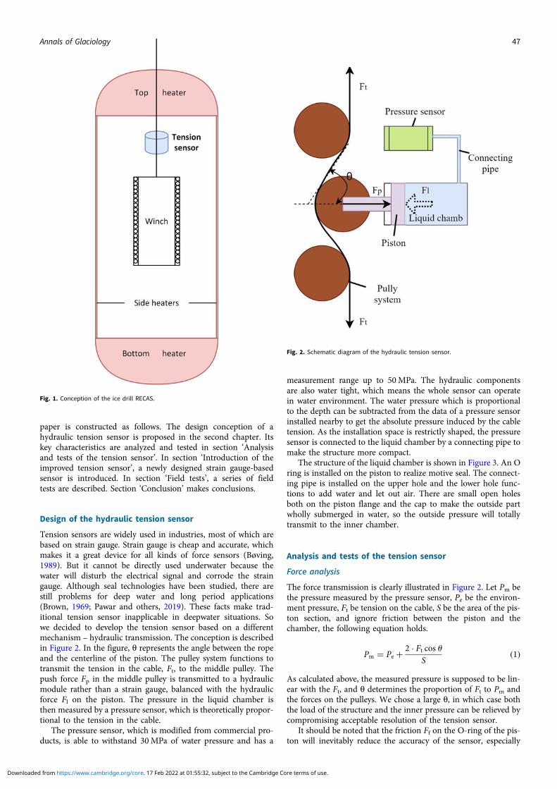
Figure 1 indicates a rough conception of RECAS. The heaters work as drills to get throughice and the winch functions to roll down the sonde during drilling and roll up during recovery.During the operation of the winch, the tension in the cable needs to be monitored to feedbackon the speed of the winch. That is, when the cable tension declines, the winch needs to slowdown to wait for the heaters to melt the ice, and when the cable tension rises, the winch shouldspeed up to keep on drilling, which is the case during downward drilling. During recovery, thesituation is reversed. Indeed, the ideal operating condition of the sonde is to keep the tensionconstantly at a preset value. This is where the problem rises: the proper operation of the winchrequires a tension sensor that works in an ice hole, which fills with water and has a size assmall as 160 mm. The design goal of RECAS is to penetrate 2500 m thickness of ice sheet,which means the tension sensor is required to withstand at least 25 MPa of water pressure.As far as we know, there are no such tension sensors that can work in deep water. Masonet al had developed an underwater sensor to measure the weight of their ice drill under thedepth up to 3400 m (Mason and others, 2007). However, no ropes are required to get throughthe sensor for this application. McLain and Rock had developed a tension sensor for moorings,which can operate in shallow water (McLain and Rock, 1992). This tension sensor needs to beattached to the cable, whereas in our case, the cable needs to slide through the sensor. In thispaper, we propose the design and analysis of two editions of deepwater tension sensors thataim to meet the requirements of RECAS ice drill. The accuracy of the final tension sensoris over 2% and the measuring range is 0–1000 kg according to our test results. The dimensionis strictly restricted to fit the inner space of RECAS, which is 150 mm × 137 mm × 86 mm. The
Downloaded from https://www.cambridge.org/core. 17 Feb 2022 at 01:55:32, subject to the Cambridge Core terms of use.
paper is constructed as follows. The design conception of ahydraulic tension sensor is proposed in the second chapter. Itskey characteristics are analyzed and tested in section ‘Analysisand tests of the tension sensor’. In section ‘Introduction of theimproved tension sensor’, a newly designed strain gauge-basedsensor is introduced. In section ‘Field tests’, a series of fieldtests are described. Section ‘Conclusion’ makes conclusions.
Design of the hydraulic tension sensor
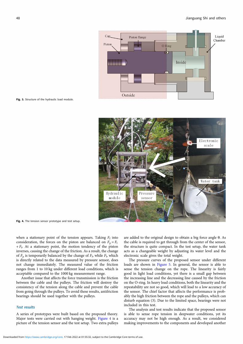
Tension sensors are widely used in industries, most of which arebased on strain gauge. Strain gauge is cheap and accurate, whichmakes it a great device for all kinds of force sensors (Bøving,1989). But it cannot be directly used underwater because thewater will disturb the electrical signal and corrode the straingauge. Although seal technologies have been studied, there arestill problems for deep water and long period applications(Brown, 1969; Pawar and others, 2019). These facts make trad-itional tension sensor inapplicable in deepwater situations. Sowe decided to develop the tension sensor based on a differentmechanism – hydraulic transmission. The conception is describedin Figure 2. In the figure, θ represents the angle between the ropeand the centerline of the piston. The pulley system functions totransmit the tension in the cable, Ft, to the middle pulley. Thepush force Fp in the middle pulley is transmitted to a hydraulicmodule rather than a strain gauge, balanced with the hydraulicforce Fl on the piston. The pressure in the liquid chamber isthen measured by a pressure sensor, which is theoretically propor-tional to the tension in the cable.
The pressure sensor, which is modified from commercial pro-ducts, is able to withstand 30MPa of water pressure and has a
measurement range up to 50MPa. The hydraulic componentsare also water tight, which means the whole sensor can operatein water environment. The water pressure which is proportionalto the depth can be subtracted from the data of a pressure sensorinstalled nearby to get the absolute pressure induced by the cabletension. As the installation space is restrictly shaped, the pressuresensor is connected to the liquid chamber by a connecting pipe tomake the structure more compact.
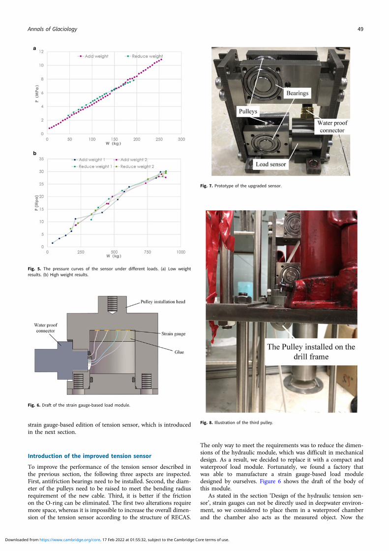
The structure of the liquid chamber is shown in Figure 3. An Oring is installed on the piston to realize motive seal. The connect-ing pipe is installed on the upper hole and the lower hole func-tions to add water and let out air. There are small open holesboth on the piston flange and the cap to make the outside partwholly submerged in water, so the outside pressure will totallytransmit to the inner chamber.
Analysis and tests of the tension sensor
Force analysis
The force transmission is clearly illustrated in Figure 2. Let Pm bethe pressure measured by the pressure sensor, Pe be the environ-ment pressure, Ft be tension on the cable, S be the area of the pis-ton section, and ignore friction between the piston and thechamber, the following equation holds.
Pm = Pe + 2 · Ft cos uS
(1)
As calculated above, the measured pressure is supposed to be lin-ear with the Ft, and θ determines the proportion of Ft to Pm andthe forces on the pulleys. We chose a large θ, in which case boththe load of the structure and the inner pressure can be relieved bycompromising acceptable resolution of the tension sensor.
It should be noted that the friction Ff on the O-ring of the pis-ton will inevitably reduce the accuracy of the sensor, especially
Fig. 1. Conception of the ice drill RECAS.
Fig. 2. Schematic diagram of the hydraulic tension sensor.
Annals of Glaciology 47
Downloaded from https://www.cambridge.org/core. 17 Feb 2022 at 01:55:32, subject to the Cambridge Core terms of use.
when a stationary point of the tension appears. Taking Ff intoconsideration, the forces on the piston are balanced on Fp = Fl+ Ff. At a stationary point, the motion tendency of the pistoninverses, causing the change of the friction. As a result, the changeof Fp is temporarily balanced by the change of Ff, while Fl, whichis directly related to the data measured by pressure sensor, doesnot change immediately. The measured value of the frictionranges from 1 to 10 kg under different load conditions, which isacceptable compared to the 1000 kg measurement range.
Another issue that affects the force transmission is the frictionbetween the cable and the pulleys. The friction will destroy theconsistency of the tension along the cable and prevent the cablefrom going through the pulleys. To avoid these results, antifrictionbearings should be used together with the pulleys.
Test results
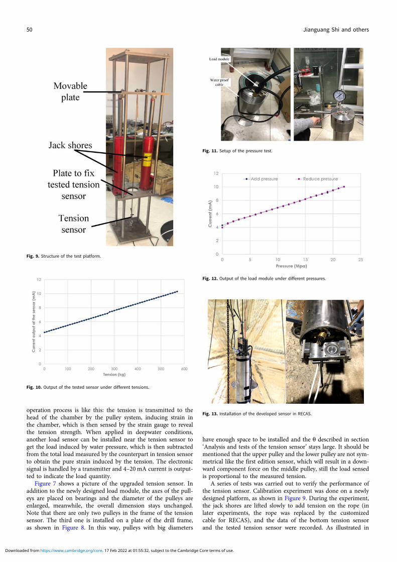
A series of prototypes were built based on the proposed theory.Major tests were carried out with hanging weight. Figure 4 is apicture of the tension sensor and the test setup. Two extra pulleys
are added to the original design to obtain a big force angle θ. Asthe cable is required to get through from the center of the sensor,the structure is quite compact. In the test setup, the water tankacts as a changeable weight by adjusting its water level and theelectronic scale gives the total weight.
The pressure curves of the proposed sensor under differentloads are shown in Figure 5. In general, the sensor is able tosense the tension change on the rope. The linearity is fairlygood in light load conditions, yet there is a small gap betweenthe increasing line and the decreasing line caused by the frictionon the O-ring. In heavy load conditions, both the linearity and therepeatability are not so good, which will lead to a low accuracy ofthe sensor. The chief factor that affects the performance is prob-ably the high friction between the rope and the pulleys, which candisturb equation (3). Due to the limited space, bearings were notincluded in this test.
The analysis and test results indicate that the proposed sensoris able to sense rope tension in deepwater conditions, yet itsaccuracy may not be high enough. As a result, we consideredmaking improvements to the components and developed another
Fig. 3. Structure of the hydraulic load module.
Fig. 4. The tension sensor prototype and test setup.
48 Jianguang Shi and others
Downloaded from https://www.cambridge.org/core. 17 Feb 2022 at 01:55:32, subject to the Cambridge Core terms of use.
strain gauge-based edition of tension sensor, which is introducedin the next section.
Introduction of the improved tension sensor
To improve the performance of the tension sensor described inthe previous section, the following three aspects are inspected.First, antifriction bearings need to be installed. Second, the diam-eter of the pulleys need to be raised to meet the bending radiusrequirement of the new cable. Third, it is better if the frictionon the O-ring can be eliminated. The first two alterations requiremore space, whereas it is impossible to increase the overall dimen-sion of the tension sensor according to the structure of RECAS.
The only way to meet the requirements was to reduce the dimen-sions of the hydraulic module, which was difficult in mechanicaldesign. As a result, we decided to replace it with a compact andwaterproof load module. Fortunately, we found a factory thatwas able to manufacture a strain gauge-based load moduledesigned by ourselves. Figure 6 shows the draft of the body ofthis module.
As stated in the section ‘Design of the hydraulic tension sen-sor’, strain gauges can not be directly used in deepwater environ-ment, so we considered to place them in a waterproof chamberand the chamber also acts as the measured object. Now the
Fig. 5. The pressure curves of the sensor under different loads. (a) Low weightresults. (b) High weight results.
Fig. 6. Draft of the strain gauge-based load module.
Fig. 7. Prototype of the upgraded sensor.
Fig. 8. Illustration of the third pulley.
Annals of Glaciology 49
Downloaded from https://www.cambridge.org/core. 17 Feb 2022 at 01:55:32, subject to the Cambridge Core terms of use.
operation process is like this: the tension is transmitted to thehead of the chamber by the pulley system, inducing strain inthe chamber, which is then sensed by the strain gauge to revealthe tension strength. When applied in deepwater conditions,another load sensor can be installed near the tension sensor toget the load induced by water pressure, which is then subtractedfrom the total load measured by the counterpart in tension sensorto obtain the pure strain induced by the tension. The electronicsignal is handled by a transmitter and 4–20 mA current is output-ted to indicate the load quantity.
Figure 7 shows a picture of the upgraded tension sensor. Inaddition to the newly designed load module, the axes of the pull-eys are placed on bearings and the diameter of the pulleys areenlarged, meanwhile, the overall dimension stays unchanged.Note that there are only two pulleys in the frame of the tensionsensor. The third one is installed on a plate of the drill frame,as shown in Figure 8. In this way, pulleys with big diameters
have enough space to be installed and the θ described in section‘Analysis and tests of the tension sensor’ stays large. It should bementioned that the upper pulley and the lower pulley are not sym-metrical like the first edition sensor, which will result in a down-ward component force on the middle pulley, still the load sensedis proportional to the measured tension.
A series of tests was carried out to verify the performance ofthe tension sensor. Calibration experiment was done on a newlydesigned platform, as shown in Figure 9. During the experiment,the jack shores are lifted slowly to add tension on the rope (inlater experiments, the rope was replaced by the customizedcable for RECAS), and the data of the bottom tension sensorand the tested tension sensor were recorded. As illustrated in
Fig. 9. Structure of the test platform.
Fig. 10. Output of the tested sensor under different tensions.
Fig. 11. Setup of the pressure test.
Fig. 12. Output of the load module under different pressures.
Fig. 13. Installation of the developed sensor in RECAS.
50 Jianguang Shi and others
Downloaded from https://www.cambridge.org/core. 17 Feb 2022 at 01:55:32, subject to the Cambridge Core terms of use.
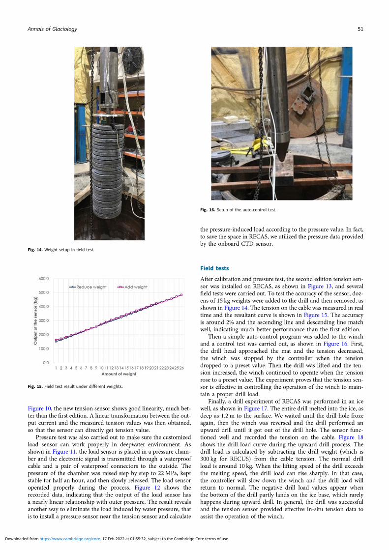
Figure 10, the new tension sensor shows good linearity, much bet-ter than the first edition. A linear transformation between the out-put current and the measured tension values was then obtained,so that the sensor can directly get tension value.
Pressure test was also carried out to make sure the customizedload sensor can work properly in deepwater environment. Asshown in Figure 11, the load sensor is placed in a pressure cham-ber and the electronic signal is transmitted through a waterproofcable and a pair of waterproof connectors to the outside. Thepressure of the chamber was raised step by step to 22MPa, keptstable for half an hour, and then slowly released. The load sensoroperated properly during the process. Figure 12 shows therecorded data, indicating that the output of the load sensor hasa nearly linear relationship with outer pressure. The result revealsanother way to eliminate the load induced by water pressure, thatis to install a pressure sensor near the tension sensor and calculate
the pressure-induced load according to the pressure value. In fact,to save the space in RECAS, we utilized the pressure data providedby the onboard CTD sensor.
Field tests
After calibration and pressure test, the second edition tension sen-sor was installed on RECAS, as shown in Figure 13, and severalfield tests were carried out. To test the accuracy of the sensor, doz-ens of 15 kg weights were added to the drill and then removed, asshown in Figure 14. The tension on the cable was measured in realtime and the resultant curve is shown in Figure 15. The accuracyis around 2% and the ascending line and descending line matchwell, indicating much better performance than the first edition.
Then a simple auto-control program was added to the winchand a control test was carried out, as shown in Figure 16. First,the drill head approached the mat and the tension decreased,the winch was stopped by the controller when the tensiondropped to a preset value. Then the drill was lifted and the ten-sion increased, the winch continued to operate when the tensionrose to a preset value. The experiment proves that the tension sen-sor is effective in controlling the operation of the winch to main-tain a proper drill load.
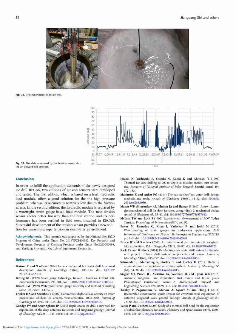
Finally, a drill experiment of RECAS was performed in an icewell, as shown in Figure 17. The entire drill melted into the ice, asdeep as 1.2 m to the surface. We waited until the drill hole frozeagain, then the winch was reversed and the drill performed anupward drill until it got out of the drill hole. The sensor func-tioned well and recorded the tension on the cable. Figure 18shows the drill load curve during the upward drill process. Thedrill load is calculated by subtracting the drill weight (which is300 kg for RECUS) from the cable tension. The normal drillload is around 10 kg. When the lifting speed of the drill exceedsthe melting speed, the drill load can rise sharply. In that case,the controller will slow down the winch and the drill load willreturn to normal. The negative drill load values appear whenthe bottom of the drill partly lands on the ice base, which rarelyhappens during upward drill. In general, the drill was successfuland the tension sensor provided effective in-situ tension data toassist the operation of the winch.
Fig. 14. Weight setup in field test.
Fig. 15. Field test result under different weights.
Fig. 16. Setup of the auto-control test.
Annals of Glaciology 51
Downloaded from https://www.cambridge.org/core. 17 Feb 2022 at 01:55:32, subject to the Cambridge Core terms of use.
Conclusion
In order to fulfill the application demands of the newly designedice drill RECAS, two editions of tension sensors were developedand tested. The first edition, which is based on a fresh hydraulicload module, offers a good solution for the the high pressureproblem, whereas its accuracy is relatively low due to the frictioneffects. In the second edition, the hydraulic module is replaced bya watertight strain gauge-based load module. The new tensionsensor shows better linearity than the first edition and its per-formance has been verified in field tests, installed in RECAS.Successful development of the tension sensor provides a new solu-tion for measuring rope tension in deepwater environment.
Acknowledgments. This research was supported by the National Key R&DProgram of China under Grant No. 2016YFC1400302, Key Research andDevelopment Program of Zhejiang Province under Grant No.2020C03098,and Zhejiang Provincial Key Lab of Equipment Electronics.
References
Benson T and 9 others (2014) Icecube enhanced hot water drill functionaldescription. Annals of Glaciology 55(68), 105–114. doi: 10.3189/2014AoG68A032.
Bøving KG (1989) Strain gauge technology. In NDE Handbook. Oxford, UK:Butterworth-Heinemann, 295–301, doi: 10.1016/B978-0-408-04392-2.50035-7.
Brown BW (1969) Waterproof strain gauge assembly and method of makingsame. US Patent 3,475,712.
Fricker HA and Scambos T (2009) Connected subglacial lake activity on lowermercer and whillans ice streams, west antarctica, 2003–2008. Journal ofGlaciology 55(190), 303–315. doi: 10.3189/002214309788608813.
Goodge JW and Severinghaus JP (2016) Rapid access ice drill: a new tool forexploration of the deep antarctic ice sheets and subglacial geology. Journalof Glaciology 62(236), 1049–1064. doi: 10.1017/jog.2016.97.
Hideki N, Yoshiyuki F, Yoshiki N, Kunio K and Akiyoshi T (1994)Thermal ice core drilling to 700 m depth at mizuho station, east antarc-tica. Memoirs of National Institute of Polar Research Special issue( 49),172–183.
Makinson K and Anker PG (2014) The bas ice-shelf hot-water drill: design,methods and tools. Annals of Glaciology 55(68), 44–52. doi: 10.3189/2014AoG68A030.
Mason WP, Shturmakov AJ, Johnson JA and Haman S (2007) A new 122mmelectromechanical drill for deep ice-sheet coring (disc): 2. mechanical design.Annals of Glaciology 47, 35–40. doi: 10.3189/172756407786857640.
McLain TW and Rock S (1992) Experimental Measurement of ROV TetherTension. Proceedings of Intervention/ROV, vol. 92.
Pawar M, Ramadas C, Khan I, Vadavkar P and Joshi M (2019)Waterproofing of strain gauges for underwater applications. 2019International Conference on Nascent Technologies in Engineering (ICNTE),pp. 1–3. doi: 10.1109/ICNTE44896.2019.8945940.
Priscu JC and 9 others (2003) An international plan for antarctic subglaciallake exploration. Polar Geography 27(1), 69–83. doi: 10.1080/789610223.
Rack FR and 8 others (2014) Developing a hot-water drill system for the wis-sard project: 1. basic drill system components and design. Annals ofGlaciology 55(68), 285–297. doi: 10.3189/2014AoG68A031.
Schwander J, Marending S, Stocker T and Fischer H (2014) Radix: aminimal-resources rapid-access drilling system. Annals of Glaciology 55(68), 34–38. doi: 10.3189/2014AoG68A015.
Siegert MJ, Priscu JC, Alekhina IA, Wadham JL and Lyons WB (2016)Antarctic subglacial lake exploration: first results and future plans.Philosophical Transactions. Series A, Mathematical, Physical, andEngineering Sciences 374(2059), 1–6. doi: 10.1098/rsta.2014.0466.
Talalay P, Zagorodnov V, Markov A, Sysoev M and Hong J (2014)Recoverable autonomous sonde (recas) for environmental exploration ofantarctic subglacial lakes: general concept. Annals of glaciology 55(65),23–30. doi: 10.3189/2014AoG65A003.
Weiss P and 5 others (2008) Study of a thermal drill head for the explorationof subsurface planetary ice layers. Planetary and Space Science 56(9), 1280–1292. doi: 10.1016/j.pss.2008.04.004.
Fig. 17. Drill experiment in an ice well.
Fig. 18. The data measured by the tension sensor dur-ing an upward drill process.
52 Jianguang Shi and others
Downloaded from https://www.cambridge.org/core. 17 Feb 2022 at 01:55:32, subject to the Cambridge Core terms of use.