Embed Size (px)
Citation preview

ELECTRICAL ENGINEERING LAB MANUAL II YEAR
1
ANNA UNIVERSITY CHENNAI
DEPARTMENT OF MECHANICAL ENGINEERING
II YEAR MECH / III SEMESTER
EE 8351- ELECTRICAL ENGINEERING LABORATORY
HOD/EEE LAB INCHARGE
Dr.M.KARTHIKEYAN PROF.S.NATARAJAN/AP/EEE

ELECTRICAL ENGINEERING LAB MANUAL II YEAR
2
Preface
This laboratory manual is prepared by the Department of Electronics and Communication
Engineering for Electrical Engineering (ME 2209) laboratory. This lab manual can be used as
instructional book for students, staff and instructors to assist in performing and understanding the
experiments. In the manual, experiments as per syllabus are described. This manual will be available
in electronic form from College’s official website, for the betterment of students.
Acknowledgement
We would like to express our profound gratitude and deep regards to the support offered by
the Chairman Shri. A.Srinivasan. We also take this opportunity to express a deep sense of gratitude
to our Principal Dr.B.Karthikeyan, M.E, Ph.D., for his valuable information and guidance, which
helped us in completing this task through various stages. We extend our hearty thanks to our head
of the department Prof.B.Revathi Sekar, M.E, (Ph.D)., for her constant encouragement and
constructive comments.
Finally the valuable comments from fellow faculty and assistance provided by the
department are highly acknowledged
ELECTRICAL ENGINEERING LAB MANUAL II YEAR
3
.
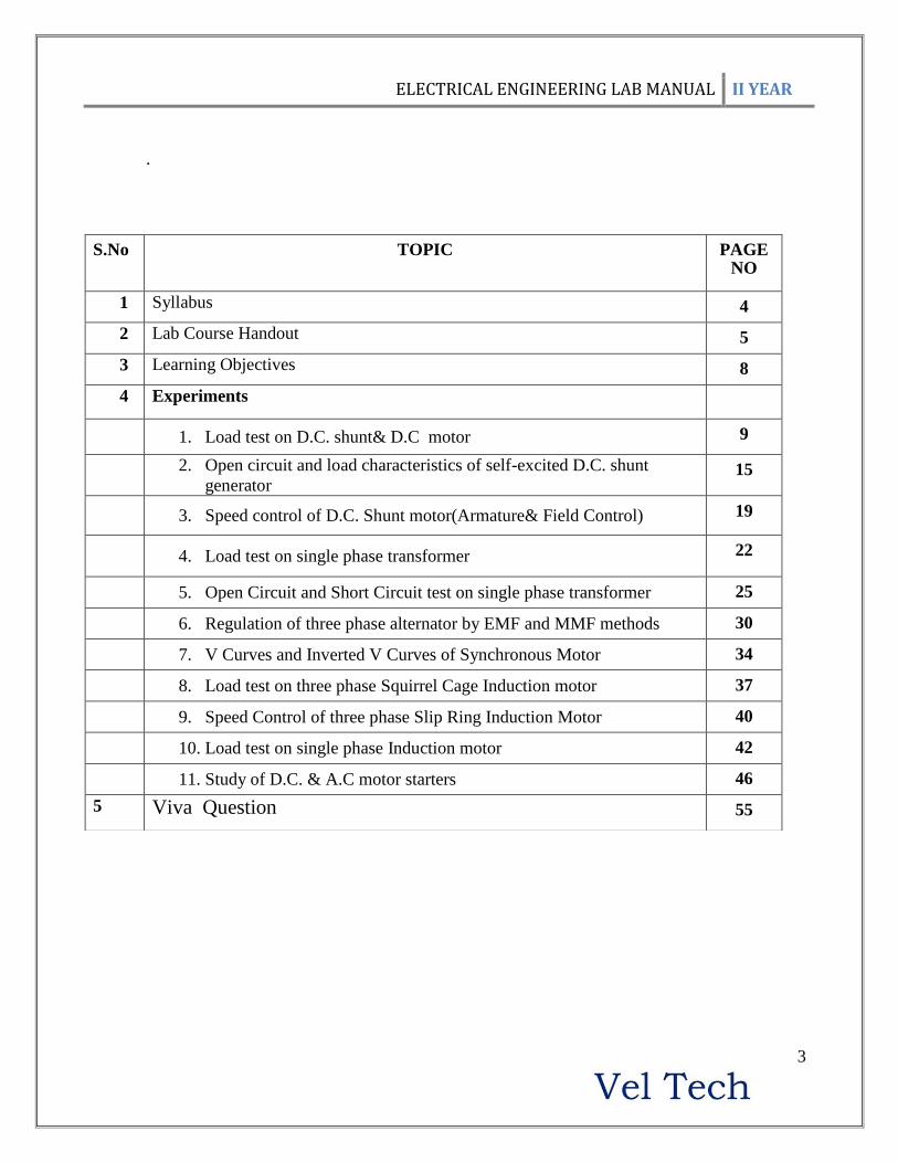
S.No TOPIC PAGE NO
1 Syllabus 4
2 Lab Course Handout 5
3 Learning Objectives 8
4 Experiments
1. Load test on D.C. shunt& D.C motor 9
2. Open circuit and load characteristics of self-excited D.C. shunt
generator 15
3. Speed control of D.C. Shunt motor(Armature& Field Control) 19
4. Load test on single phase transformer 22
5. Open Circuit and Short Circuit test on single phase transformer 25
6. Regulation of three phase alternator by EMF and MMF methods 30
7. V Curves and Inverted V Curves of Synchronous Motor 34
8. Load test on three phase Squirrel Cage Induction motor 37
9. Speed Control of three phase Slip Ring Induction Motor 40
10. Load test on single phase Induction motor 42
11. Study of D.C. & A.C motor starters 46
5 Viva Question 55

ELECTRICAL ENGINEERING LAB MANUAL II YEAR
4
SYLLABUS
EE8351 – ELECTRICAL ENGINEERING LABORATORY
LIST OF EXPERIMENTS
1. Load test on D.C. shunt& D.C motor.
2. Open circuit and load characteristics of self-excited D.C. shunt generator.
3. Speed control of D.C. Shunt motor (Armature& Field Control).
4. Load test on single phase transformer.
5. Open Circuit and Short Circuit test on single phase transformer.
6. Regulation of three phase alternator by EMF and MMF methods.
7. V Curves and Inverted V Curves of Synchronous Motor.
8. Load test on three phase Squirrel Cage Induction motor.
9. Speed Control of three phase Slip Ring Induction Motor.
10. Load test on single phase Induction motor.
11. Study of D.C. & A.C motor starters.

ELECTRICAL ENGINEERING LAB MANUAL II YEAR
5
Subject code : EE:8361
Subject Title : Electrical Engineering Lab
Staff name : S.NATARAJAN
Scope and Objective of the Subject:
To expose the students to the basic operation of electrical machines and help them
develop experimental skills.
To study the concepts, performance characteristics, time and frequency response of linear
systems and study the effects of controllers.
Course Plan / Schedule:
S.No Topics to be covered Learning objectives Page
No*
No. of
hours
1 Load test on D.C. shunt& D.C
motor
Students will be exposed to the
performance characteristics D.C. shunt
& Series motors.
9
3 hrs.
2
Open circuit and load
characteristics of self-excited D.C.
shunt generator
Students will be exposed to the
concepts of Critical resistance(Rc),
O.C.C at the specified speed, External
Characteristics, and Internal
Characteristics.
15
3hrs
3 Speed control of D.C. Shunt motor
(Armature& Field Control).
Students will understand speed control
methods of D.C. shunt motor and the
relation between armature voltage,
field current and speed of D.C. Shunt
motor.
19
3hrs
4 Load test on single phase
transformer
The students will understand direct
load test on the given single phase
transformer and determination
procedures of efficiency and
regulation at different loads.
22
3hrs
5 Open Circuit and Short Circuit test
on single phase transformer
The students will understand O.C and
S.C tests, Equivalent circuit &
Predetermination procedures of
efficiency and regulation at different
loads
25
3hrs
6 Regulation of three phase alternator
by EMF and MMF methods
Students will be exposed to the
concepts of predetermination of
Voltage regulation by EMF & MMF
methods. Students will be exposed to
30
3hrs

ELECTRICAL ENGINEERING LAB MANUAL II YEAR
6
the performance characteristics of the
machine
7 V Curves and Inverted V Curves of
Synchronous Motor
Students will be exposed to relation
between field current, armature current
and power factors at various load
levels.
34
3hrs
8 Load test on three phase Squirrel
Cage Induction motor
Students will be exposed to the
performance characteristics of the
three phase Squirrel Cage Induction
motor.
37
3hrs
9 Speed control of three phase slip
ring induction motor.
Students will be exposed to the effect
of stator voltage and rotor resistance
on the speed of the three phase slip
ring induction motor.
40
3hrs
10 Load test on single phase Induction
motor
Students will be exposed to the
performance characteristics of single
phase Induction motor.
42 3hrs
11 Study of D.C. motor and induction
motor starters
Students will be exposed to different
kinds of D.C and induction motor
starters
46
3hrs
*-As in Lab Manual

ELECTRICAL ENGINEERING LAB MANUAL II YEAR
7
Evaluation scheme – Internal Assessment
Timings for chamber consultation: Students can contact the Course Instructor in her/his chamber
during lunch break.
STUDENTS GUIDELINES
There are 3 hours allocated to a laboratory session in Electrical Engineering and Control
System Lab. It is a necessary part of the course at which attendance is compulsory.
Here are some guidelines to help you perform the Experiments effectively:
1. Read all instructions carefully and proceed according to that.
2. Ask the faculty if you are unsure of anything program or any concept.
3. Write up full and suitable conclusions for each experiment.
4. After completing the experiment complete the observation and get signature from the staff.
5. Before coming to next lab make sure that you complete the record and get sign from the
faculty.
STAFF SIGNATURE HOD
EC
No.
Evaluation
Components
Duration Weightage
1 Observation Continuous 20%
2 Record Continuous 30%
3 Attendance Continuous 30%
4 Model lab 3hr 20%

ELECTRICAL ENGINEERING LAB MANUAL II YEAR
8
LEARNING OBJECTIVES
1. To expose the students to the basic operations of electrical machines and to help them develop
their experimental skills.
2. To study the concepts, performance characteristics of electrical machines and starters
.PRECAUTIONS: (Not to be included in the Record)
1. Fuse carriers must be removed while giving electrical connections to Equipments.
2. Sliding contact positions of the various rheostats must be checked before starting the
Experiment.
3. SPST/DPST/TPST switches must be kept open till staff members verify and approve the
connections.
4. The following Guidelines must be followed for selection of appropriate Fuse, Meter and
Rheostat ranges:
Fuses for Motor/Generator sets
(i) For no-load tests -45% of rated current.
(ii) For Load tests-120% of rated current
Fuses for Transformers
(i) For no-load tests -10% of rated current.
(ii) For Load tests-120% of rated current
Meter range
Meters of nearest higher range available can be selected
Rating of Rheostat:
(i) Current rating- should be selected based on the basis of the current rating of the
circuit, to be fed through the rheostat.
(ii)Resistance rating- should be selected based on the current limitations/Speed
limitations to be imposed to the circuit fed through the rheostat.
5. Fuse carriers with appropriate fuse wires must be inserted into the fuse holders/bases and the
Experiment must be carried out after the circuit connections are checked and approved by the staff-
in-charge.

ELECTRICAL ENGINEERING LAB MANUAL II YEAR
9
Ex. No: 1.A
Date:
LOAD TEST ON DC SHUNT MOTOR
Aim:
To conduct load test on DC shunt motor and compound motor and draw the characteristic
curves
Exercise
Draw the following characteristic curves for DC shunt motor
i. Output Vs η%
ii. Output Vs T
iii. Output Vs N
iv. Output Vs IL
v. Torque Vs N
Apparatus Required:
Sl.no Name of the component type Range Quantity
-
Name plate details:
MOTOR
Fuse rating calculation for field and armature:
Load test
120 % of rated current
Formulae Used:
(i) Torque = )2
(81.9)~( 21
tRSS in N-M
S1, S2 – spring balance readings in Kg
R- Break drum radius in m
(ii) Input power = V x I in Watts
(iii) Output power = 2NT / 60 in Watts
ELECTRICAL ENGINEERING LAB MANUAL II YEAR
10
N – Speed of the motor in RPM
(iv) Percentage of efficiency = (Output power /Input power) x 100.
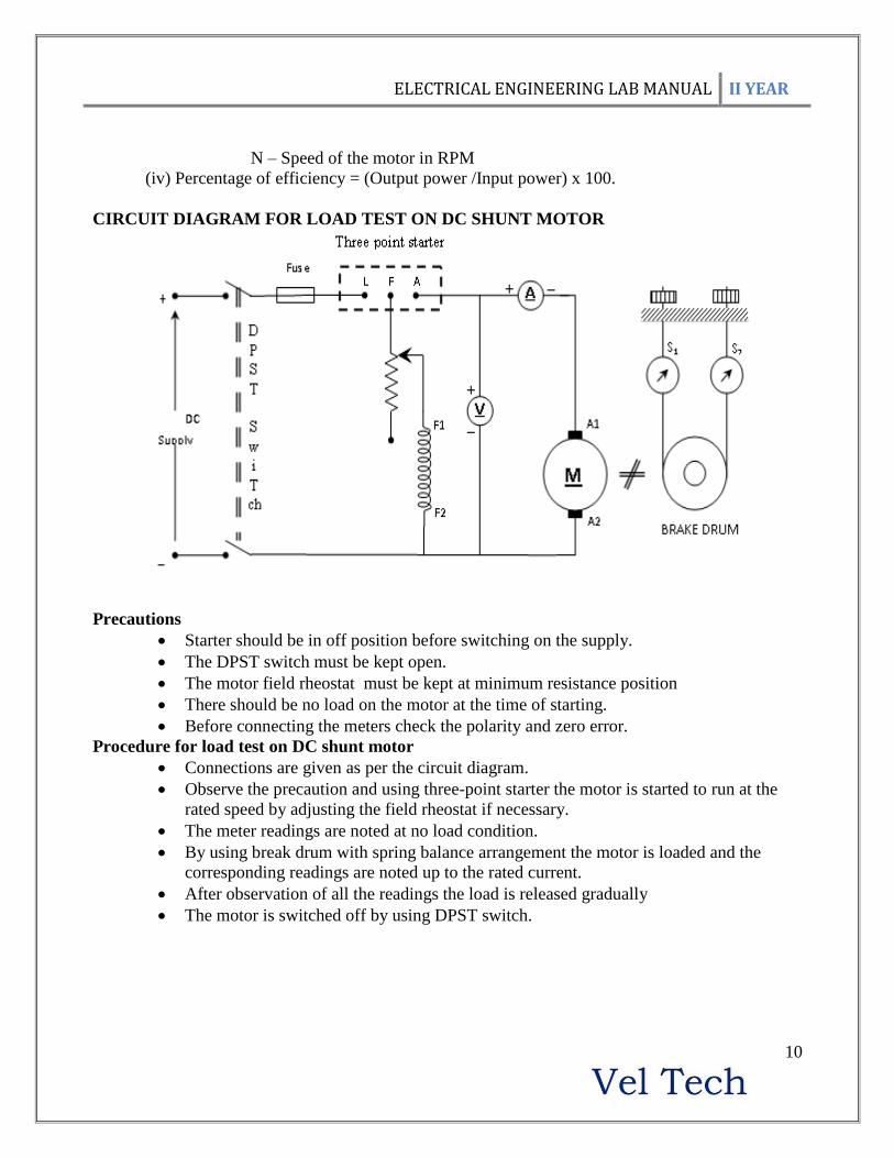
CIRCUIT DIAGRAM FOR LOAD TEST ON DC SHUNT MOTOR
Precautions
Starter should be in off position before switching on the supply.
The DPST switch must be kept open.
The motor field rheostat must be kept at minimum resistance position
There should be no load on the motor at the time of starting.
Before connecting the meters check the polarity and zero error.
Procedure for load test on DC shunt motor
Connections are given as per the circuit diagram.
Observe the precaution and using three-point starter the motor is started to run at the
rated speed by adjusting the field rheostat if necessary.
The meter readings are noted at no load condition.
By using break drum with spring balance arrangement the motor is loaded and the
corresponding readings are noted up to the rated current.
After observation of all the readings the load is released gradually
The motor is switched off by using DPST switch.

ELECTRICAL ENGINEERING LAB MANUAL II YEAR
11
TABULATION FOR LOAD TEST ON DC SHUNT MOTOR
Radius of the brake drum (R) = in m Thickness of the belt (t) = in m
Sl
No
Load
Voltage
in
Volts
Load
current
I
Amps
speed
in
rpm
Spring balance
Reading
In kg
Input
Power
in
Watts
Torque
in NM
Output
Power
in
Watts
Efficiency
in %
S1 S2 S1S2
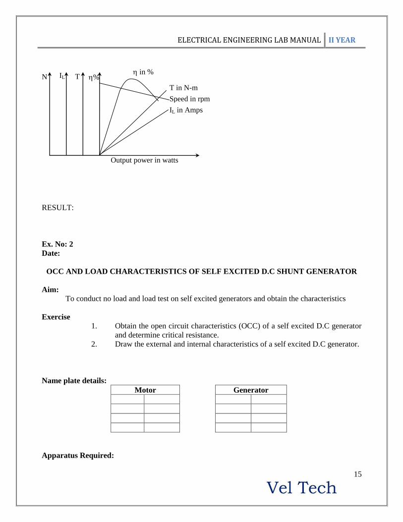
MODEL GRAPH
(A) Electrical characteristics
in %
T in N-m
Speed in rpm
IL in Amps
N IL T %
Output power in watts

ELECTRICAL ENGINEERING LAB MANUAL II YEAR
12
(B) Mechanical characteristics
(C) Torque, Speed Vs Load current
Model calculation:
Graph:
Output Vs η%
Output Vs T
Output Vs N
Output Vs IL
Torque Vs N
Result:
T Vs N
Sp
eed
(N
) in
rpm
Torque ( T ) in N-m
Torq
ue
(T)
in N
-m
Spee
d (
N)
in r
pm
IL Vs N
Load current (IL) in Amps
IL Vs T

ELECTRICAL ENGINEERING LAB MANUAL II YEAR
13
EXPT. No: 1.B
Date:
LOAD TEST ON DC SERIES MOTOR
AIM:
To conduct load test on the given DC Series Motor and determine the performance characteristics.
APPARATUS REQUIRED:
Sl.no Description Type Specification Quantity
PRECAUTIONS:
1. The motor should be started and stopped with load
2. Brake drum should be cooled with water when it is under load.
PROCEDURE:
1. Connections are made as per the circuit diagram.
2. After checking the load condition, DPST switch is closed and starter resistance is gradually
removed.
3. For various loads, Voltmeter, Ammeter readings, speed and spring balance readings are noted.
4. After bringing the load to initial position, DPST switch is opened.
CIRCUIT DIAGRAM:

ELECTRICAL ENGINEERING LAB MANUAL II YEAR
14
TABULAR COLUMN:
MODEL GRAPH:
ELECTRICAL ENGINEERING LAB MANUAL II YEAR
15
RESULT:
Ex. No: 2
Date:
OCC AND LOAD CHARACTERISTICS OF SELF EXCITED D.C SHUNT GENERATOR
Aim:
To conduct no load and load test on self excited generators and obtain the characteristics
Exercise
1. Obtain the open circuit characteristics (OCC) of a self excited D.C generator
and determine critical resistance.
2. Draw the external and internal characteristics of a self excited D.C generator.
Name plate details:
Motor Generator
Apparatus Required:
in %
T in N-m
Speed in rpm
IL in Amps
N IL T %
Output power in watts
ELECTRICAL ENGINEERING LAB MANUAL II YEAR
16
Sl.no Description Type Specification Quantity
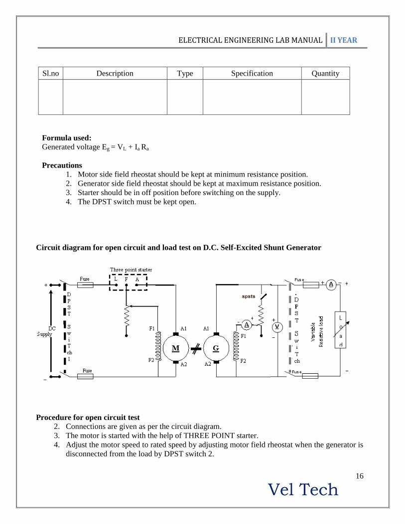
Formula used:
Generated voltage Eg = VL + Ia Ra
Precautions 1. Motor side field rheostat should be kept at minimum resistance position.
2. Generator side field rheostat should be kept at maximum resistance position.
3. Starter should be in off position before switching on the supply.
4. The DPST switch must be kept open.
Circuit diagram for open circuit and load test on D.C. Self-Excited Shunt Generator
Procedure for open circuit test
2. Connections are given as per the circuit diagram.
3. The motor is started with the help of THREE POINT starter.
4. Adjust the motor speed to rated speed by adjusting motor field rheostat when the generator is
disconnected from the load by DPST switch 2.

ELECTRICAL ENGINEERING LAB MANUAL II YEAR
17
5. By varying the generator field rheostat gradually, the open circuit voltage [Eo] and
corresponding field current (If) are tabulated up to 120 % of rated voltage of generator.
6. The motor is switched off by using DPST switch 1 after bringing all the rheostats to initial
position.
Procedure for Load test:
1. Connections are given as per the circuit diagram
2. The prime mover is started with the help of three point starter and it is made to run at rated speed
when the generator is disconnected from the load by DPST switch 2.
3. By varying the generator field rheostat gradually, the rated voltage [Eg] is obtained.
4. The ammeter and voltmeter readings are observed at no load condition.
5. The ammeter and voltmeter readings are observed for different loads up to the rated current by
closing the DPST switch 2.
6. After tabulating all the readings the load is brought to its initial position.
7. The motor is switched off by using DPST switch 1 after bringing all the rheostats to initial
position.
Tabulation for Open Circuit Test on Separately Excited D.C Shunt Generator:
Sl.no Field
current in
Amps [If]
Open circuit
voltage in
Volts [Eo]
Tabulation for Load Test:
Sl.no
Load
current
[IL] in
Amps
Load
voltage
[VL] in
Volts
Field
current If in
amps
Armature
current
[Ia] in
Amps
(Ia=If+IL)
Armature
drop=
Ia* Ra in
volts
Generated emf
[Eg = VL+IaRa] in
volts

ELECTRICAL ENGINEERING LAB MANUAL II YEAR
18
Circuit diagram for find the generator armature resistance [Ra]
Procedure for find armature resistance Ra:
1. Connections are given as per circuit diagram
2. Check loading rheostat must be at maximum resistance position.
3. Close the DPST switch and vary the loading rheostat for various values in steps and noted
the corresponding voltmeter and ammeter reading.
4. Open the DPST switch after loading rheostat begins its initial position.
Tabulation for Finding Armature Resistance:
Sl.no Armature voltage
Va in volts
Armature current
Ia in amps Ra = Va/ Ia in ohms
Model graph
Open circuit characteristics
Internal (Eg Vs Ia) and External (VL Vs IL) characteristics
If
Field current
[If] in amps
Open
cir
cuit
volt
age
in
Volt
s [E
o]
Eo Vs If

ELECTRICAL ENGINEERING LAB MANUAL II YEAR
19
Result:
Ex. No: 3
Date:
SPEED CONTROL OF DC SHUNT MOTOR
Aim
To study the speed control characteristics of DC shunt motor (Armature control and Field
control)
Exercise
1. Draw the following curves for
a. If Vs N at Different fixed values of Va
b. Va Vs N at different fixed values of If
Apparatus Required:
Sl.no Name of the component type Range Quantity
Load current [IL] in amps
Armature current [Ia] in amps
Load
volt
age
in V
olt
s [V
L]
Gen
erat
ed e
mf
in V
olt
s [E
g]
Eg Vs Ia
VL Vs IL

ELECTRICAL ENGINEERING LAB MANUAL II YEAR
20
Name plate details:
Motor
Speed
Type
Field Armature
Fuse rating calculation:
CIRCUIT DIAGRAM
Precaution:

ELECTRICAL ENGINEERING LAB MANUAL II YEAR
21
The DPST switch must be kept open while giving connections.
At the time of starting, the motor field rheostat must be kept at minimum resistance
position and the armature rheostat must be kept at maximum resistance position.
Before connecting the meters check the polarity and zero error.
Procedure
Connections are given as per the circuit diagram.
Observe the precaution and switch ON the supply.
By adjusting the field rheostat get the motor speed to rated speed
A. Armature Control Method
Keep the Field Current Constant
By adjusting armature rheostat the speed and armature voltage are noted.
Repeat the same procedure for various positions.
B. Field Control Method
Keep the armature voltage constant.
By adjusting the field rheostat various field currents and voltage are noted.
Repeat the same procedure for various positions
Tabulation for Armature Control Method
Field current If1 Field current If2
Armature
voltage Va Speed N in RPM
Armature
voltage Va
Speed N in
RPM
Tabulation for Field Control Method
Armature Voltage Va1 Armature Voltage Va2
Field Current If
In AMPS Speed N in RPM
Field Current
If In AMPS
Speed N in
RPM

ELECTRICAL ENGINEERING LAB MANUAL II YEAR
22
MODEL GRAPH:
Result:
EXPT NO: 4.
Date :
LOAD TEST ON SINGLE PHASE TRANSFORMER
AIM:
To conduct a direct load test on the given single phase transformer and to determine the
efficiency and regulation at different load conditions.
NAME PLATE DETAILS:
KVA rating =
Rated H.V side Voltage =
Rated L.V side Voltage =
INSTRUMENTS AND EQUIPMENTS REQUIRED:
S.No Equipment Type Range Quantity
1.
2.
3.

ELECTRICAL ENGINEERING LAB MANUAL II YEAR
23
4.
5.
THEORY:
Direct load test is conducted to determine the efficiency characteristics and regulation
characteristics of the given transformer.
An ideal transformer is supposed to give constant secondary voltage irrespective of the load
current. But, practically the secondary voltage decreases as the transformer is loaded due to primary
and secondary impedance drops. Since these drops are dependent on load current, this variation in
terminal voltage is found using direct loading.
PRECAUTIONS:
1. Remove the fuse carriers before wiring and start wiring as per the circuit diagram.
2. Fuse Calculations: This being a load test, the required fuse ratings are 120% of rated current.
CIRCUIT DIAGRAM:
PROCEDURE:
1. The circuit connections are made as per the circuit diagram as shown in figure.
2. Keeping the autotransformer in its minimum position and the DPST switch in open position, the
main supply is switched ON.

ELECTRICAL ENGINEERING LAB MANUAL II YEAR
24
3. By slowly and carefully operating the Auto transformer the rated voltage (115V) is applied to the
L.V side of the transformer.
4. Under no-load condition, one set of readings namely VH.V, IH.V, WH.Vs, VL.V, WL.V, are recorded in
the tabular column.
5. The DPST switch on the load side is now closed and the load is increased in gradual steps and at
each step all meter readings are noted down in the tabular column.
6. The procedure is continued until the current on the H.V side is equal to its full load value.
7. After the experiment is completed, the load is decreased to its minimum, the auto transformer is
brought back to its original position and then the main supply is switched OFF.
CALCULATIONS:-
I. EFFICIENCY CALCULATION:
i . The efficiency of the transformer for each set of reading is calculated and tabulated
using the expression,
100% XInput
Output
where,
The output of the transformer = WH.V on the H.V side
The input of the transformer = WL.V = Wattmeter reading on the L.V side
ii . A Graph is plotted between the percentage efficiency and the output, taking %
efficiency on Y-axis and the output on X-axis, as shown in figure.
II . VOLTAGE REGULATION (down) CALCULATIONS: -
i . The regulation is calculated and tabulated for each set of readings using the
expression ,
100Re%
)(.
)(.)(.X
V
VVgulation
NoloadVH
loadVHNolaadVH
where,
VH.V(No-load) - is the no-load voltage on the H.V side .
VH.V(Load) - is the actual voltage on the H.V side under load condition .
ii . A Graph is plotted b=�ween the percentage regulation and the output taking % regulation on
Y-axis and the output on X- axis as shown in figure.
TABULAR COLUMN:
Sl.
No
Input Out put
(%)
%V reg
VL.V
IL.V
WL.V
(W)
VH.V
(V)
IH.V
(A)
WH.V
(watts)

ELECTRICAL ENGINEERING LAB MANUAL II YEAR
25
MODEL CALCULATION:
MODEL GRAPH:
RESULT: -
Ex. No: 5
Date:
OC AND SC TESTS ON SINGLE PHASE TRANSFORMER
Aim:
To conduct open circuit and short circuit test and to predetermine the efficiency of the
transformer at desired load and power factor and to calculate the regulation at different power factor
Exercise
1. Determine the equivalent circuit of the transformer.
2. Predetermine the efficiency at different load at UPF and 0.8 Power factor lagging.
3. Predetermine the full load regulation at different power factor.
4. Draw the following curves
a. Output Vs η%
b. Power factor Vs %Regulation
Apparatus Required:
Sl.no Name of the component type Range Quantity

ELECTRICAL ENGINEERING LAB MANUAL II YEAR
26
-
Name plate details:
Transformer
Fuse calculation for transformer (O.C and S.C test):
Primary current IP = KVA rating of the transformer /primary voltage.
Secondary current IS =KVA rating of transformer / secondary voltage.
O.C test
10 % of rated primary current
S.C test
125 % of rated secondary current
Formulae Used:
Open circuit test:
1. No load power factor ococ
oc
IV
W
)(cos 0
WOC = open circuit power in watts
VOC = open circuit voltage in volts
IOC = open circuit current in amps
2. No load working component resistance (RO); oOC
OC
OCosI
VR
in ohms
3. No load magnetizing component (XO); oOC
OC
OSinI
VX
in ohms
Short circuit test:
4. Equivalent impedance referred to HV side (Z02); SC
SC
OI
VZ 2 in ohms.
5. Equivalent resistance referred to HV side (R02); 22
SC
SCO
I
WR in ohms
6. Equivalent reactance referred to HV side (X02); 2
2
2
22 OOO RZX in ohms
7. Transformation ratio (K); 1
2
V
VK
8. Equivalent resistance referred to LV side (R01); 2
2
1K
RR O
O in ohms
ELECTRICAL ENGINEERING LAB MANUAL II YEAR
27
9. Equivalent reactance referred to LV side (X01); 2
2
1K
XX O
O in ohms
Efficiency and regulation
10. Output power = )( CosKVAX in watts
11. Chopper loss = )( 2
SCWX in watts
12. Total loss WT = )( lossIronlossCu in watts
13. Efficiency = 100 lossTotalpowerOutput
powerOutputin %
14. Regulation = 100[
2
22
O
OOSC
V
SinXCosRIX in %
Precautions:
1. Auto transformer should be kept at zero volt position.
2. At the time of starting the experiment DPST switch kept open and transformer should be no
load.
3. High voltage and low voltage sides of the transformer should be properly used as primary or
secondary respective to experiments.
Procedure (for Open circuit Test)
Connections are given as per the circuit diagram.
Ensuring the precautions, supply is switched on by closing DPST switch.
Auto transformer is adjusted to energize the transformer with primary voltage on LV side.
Voltmeter, ammeter and wattmeter readings are noted at no load condition.
Auto transformer is gradually decreased to its initial position.
Switch off the supply by DPST.
Procedure (for Short CKT Test)
Connections are given as per the circuit diagram.
Ensuring the precautions the supply is switched on by closing DPST switch.
Auto transformer is adjusted to energize the transformer with primary current on the HV
side.
Voltmeter, ammeter and wattmeter readings are noted at no load condition.
Auto transformer is gradually decreased to its initial position.
Switch off the supply by DPST.
Circuit diagram for open circuit test of 1 transformer

ELECTRICAL ENGINEERING LAB MANUAL II YEAR
28
Circuit diagram for short circuit test of 1 transformer
Tabulation for OC Test multiplication factor:
Sl.
no
Open circuit
primary current
(IOC)
In Amps
Open circuit
primary voltage
(VOC) in Volts
Open circuit power
(Woc) in Watts Open circuit
Secondary
voltage in volts Observed Actual

ELECTRICAL ENGINEERING LAB MANUAL II YEAR
29
Tabulation for SC Test multiplication factor:
Sl.
No
Short circuit
primary current
(ISC)
In Amps
Short circuit
primary voltage
(VSC) in Volts
Short circuit power
(Wsc) in Watts Short circuit
Secondary
Current in Amps Observed Actual
Predetermination of efficiency:
Core (or) Iron loss (Wi) = Watts, KVA rating of Transformer = .
Rated Short circuit current = Amps Short Circuit power at rated current (WSC) =
.
Fractio
n of
load/
Load
factor
(X)
Output power
1000* )( CosKVAX
in watts at Various P.F
Copper loss
at various
loads
)( 2
SCWX
in watts
Total loss
in watts WT=
(Woc ) +(X2
*Wsc)
Efficiency at Various P.F
TWpo
po
/
/
* (100 ) in %
0.2 0.4 0.6 0.8 1 0.2 0.4 0.6 0.8 1
¼
½
¾
1
Tabulation to predetermine % Voltage regulation:
ISC = RO2= XO2= V2O=
Load
factor
% V regulation at loads of
Leading p.f
Unity
p.f
% V regulation at loads of
Lagging p.f

ELECTRICAL ENGINEERING LAB MANUAL II YEAR
30
0.2 0.4 0.6 0.8 0.2 0.4 0.6 0.8
0.2
0.4
0.6
0.8
Model graph
1) Efficiency 2) Regulation
Result:
Ex. No: 6
Date:
Predetermination of Regulation of Three Phase Alternator by EMF and MMF Methods

ELECTRICAL ENGINEERING LAB MANUAL II YEAR
31
AIM:
To predetermine the regulation of three phase alternator by EMF and MMF methods at
various loadsby conducting O.C and S.C tests.
Name plate details:
3 Alternator DC Shunt Motor
Fuse rating:
125 % of current (Full load current)
For dc shunt motor.
For alternator
Apparatus required:
Sl. no Description Type Range Quantity
Formulae used:
Emf method:
A.C Armature resistance Rac = 1.4 Rdc where - Rdc is the resistance in DC supply.
Synchronous impedance Zs = Open circuit voltage (E1 (ph))/short circuit current (Isc)
Synchronous impedance Xs = (Zs2-Ra
2)
Open circuit voltage Eo = ((Vrated cos + Ia Ra) 2
+ (Vrated sin +IaXs)2) (For lagging power
factor)
Open circuit voltage Eo = ((Vrated cos + Ia Ra)2+(Vrated sin - IaXs)
2) (For leading power
factor)
Open circuit voltage Eo = ((Vrated cos + Ia Ra)2+( IaXs)
2) (For unity power factor)
Percentage regulation = ((Eo-Vrated) /Vrated)*100(For both EMF and MMF methods)
Precaution:
i. The motor field rheostat should be kept in the minimum resistance position.
ii. The alternator field potential divider should be in the minimum voltage position.

ELECTRICAL ENGINEERING LAB MANUAL II YEAR
32
iii. Initially all switches are in open position.
Experimental Procedure for both E.M.F and MMF method:
1. Note down the nameplate details of motor and alternator.
2. Connections are made as per the circuit diagram.
3. Give the supply by closing the dust switch.
4. Using the three point starter, start the motor to run at the synchronous speed by varying the
motor filed rheostat.
5. Conduct an open circuit test by varying the potential divider for various values of field
current and tabulate the corresponding open circuit voltage readings.
6. Conduct a short circuit test by closing the TPST switch and adjust the potential divider to set
the rated armature current, tabulate the corresponding field current.
7. Conduct a stator resistance test (Measurement of Armature D.C resistance per phase.) and
calculate the Armature A.C resistance per phase.
Procedure to draw the graph for EMF method:
1. Draw the open circuit characteristics curve (generator voltage per phase Vs field current)
2. Draw the short circuit characteristics curve (short circuit current Vs field current)
3. From the graph find the open circuit voltage per phase (E1 (ph)) for the rated short circuit
current (Isc).
4. By using respective formulae find the Zs, Xs, Eo and percentage regulation.
CIRCUIT DIAGRAM FOR O.C AND S.C TESTSON 3 PHASE ALTERNATOR:
ELECTRICAL ENGINEERING LAB MANUAL II YEAR
33
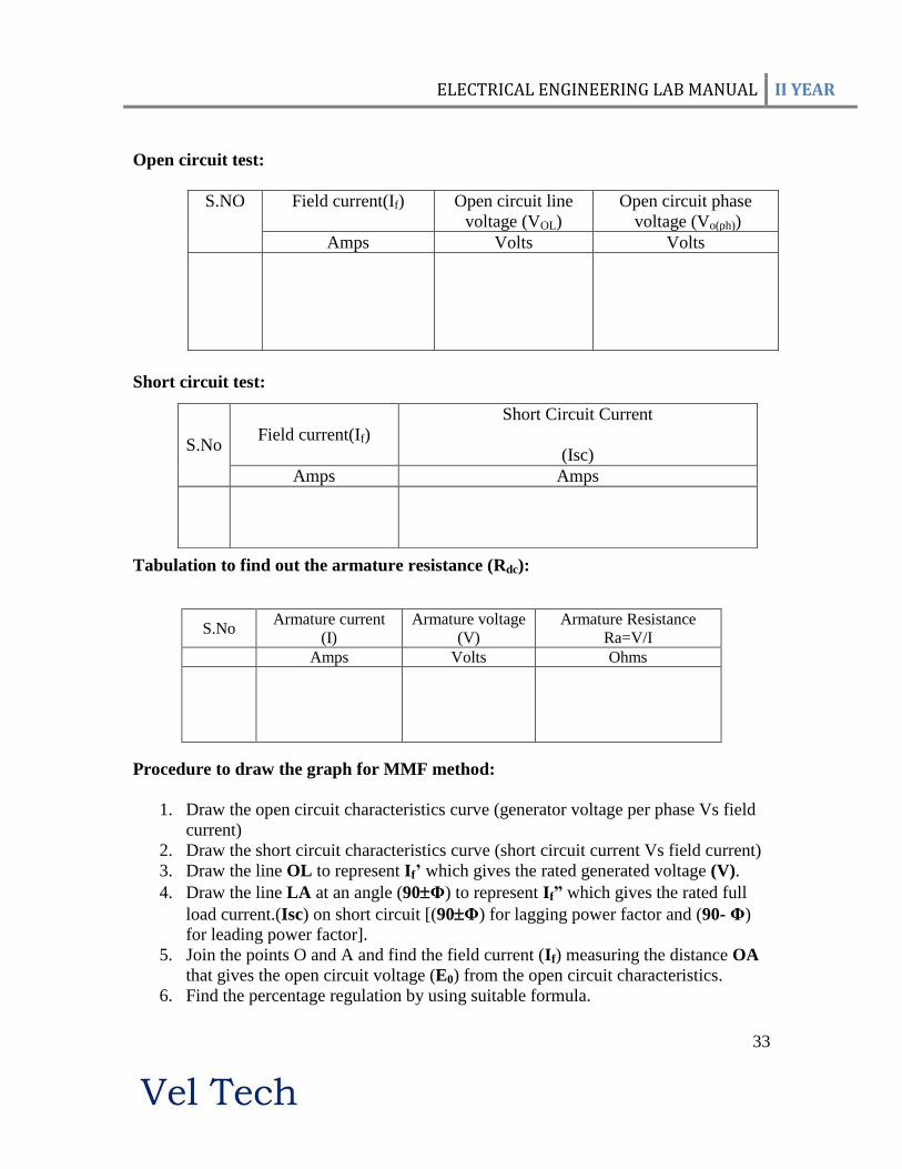
Open circuit test:
S.NO Field current(If) Open circuit line
voltage (VOL)
Open circuit phase
voltage (Vo(ph))
Amps Volts Volts
Short circuit test:
Tabulation to find out the armature resistance (Rdc):
Procedure to draw the graph for MMF method:
1. Draw the open circuit characteristics curve (generator voltage per phase Vs field
current)
2. Draw the short circuit characteristics curve (short circuit current Vs field current)
3. Draw the line OL to represent If’ which gives the rated generated voltage (V).
4. Draw the line LA at an angle (90Φ) to represent If” which gives the rated full
load current.(Isc) on short circuit [(90Φ) for lagging power factor and (90- Φ)
for leading power factor].
5. Join the points O and A and find the field current (If) measuring the distance OA
that gives the open circuit voltage (E0) from the open circuit characteristics.
6. Find the percentage regulation by using suitable formula.
S.No Field current(If)
Short Circuit Current
(Isc)
Amps Amps
S.No Armature current
(I)
Armature voltage
(V)
Armature Resistance
Ra=V/I
Amps Volts Ohms

ELECTRICAL ENGINEERING LAB MANUAL II YEAR
34
MODEL CALCULATION:
FOR EMF METHOD& MMF METHODS (Two separate Tables)
Observations of % Voltage Regulation Values at Various Load Conditions:
Load
Factor
(X)
% Voltage Regulation at Various Power Factors
Lagging UPF Leading
0.2 0.4 0.6 0.8 0.2 0.4 0.6 0.8
X= 0.25
X= 0.5
X= 0.75
X= 1.0
MODEL GRAPH ( FOR BOTH E.M.F &M.M.F METHODS)
RESULT

ELECTRICAL ENGINEERING LAB MANUAL II YEAR
35
Expt.no 7
Date:
V & INVERTED V CURVES OF THREE PHASE SYNCHRONOUS MOTOR
AIM:
To plot the V and Inverted V- Curves of the given Synchronous Motor at no-load and on
load.
NAME PLATE DETAILS:
FUSE RATING AND RANGE FIXING:
EQUIPMENTS REQUIRED:
SL NO NAME OF THE
EQUIPMENTS/INSTRUMENTS TYPE RANGE
QUANTITY
PRECUTIONS:
1. Before giving the three phase supply, the three phase variac must be kept at its
minimum position.
2. Before providing d.c. supply to the field regulator of the motor, the field regulator
should be kept at minimum position and the field winding should be kept in open
position.
3. Start the synchronous machine preferably at no-load condition.
4. During the experiment the field current should not exceed 1.5 times the rated current of
the field current and the armature current/ ph (Ia ph) should not exceed 1.25 times the rated
armature current.
PROCEDURE:
1. Make connections as per the circuit diagram.
2. Keeping the field circuit of the synchronous motor open, close the TPST switch and
vary the auto transformer to obtain the rated three phase voltage. The machine will run at

ELECTRICAL ENGINEERING LAB MANUAL II YEAR
36
a speed lesser than the synchronous speed. (with the help of damper windings as
induction motor)
3. Connect the field terminals of the synchronous motor to the d.c. supply by closing the
DPST switch and excite the field system. The machine will now begin to run at
synchronous speed by establishing magnetic locking between armature circuit and the
field system. Note down the field current, the corresponding armature current, line
voltage and wattmeter readings.
4. Vary the field current by adjusting the field excitation system and for each value of
field current (from low value of field current up to 1.5 times the rated field current) and
note down the corresponding meter readings.
5. Repeat the same procedure for various loading conditions carefully not exceeding 1.25
times the armature current and 1.5 times the rated field current.
Circuit Diagram:
TABULATION:
At N= Ns (constant) VL = Vrated
Sl. NO
. Load
Field Current If (A)
Armature
Current (A)
W1OBS W1ACT W2obs W2ac
t
Power W=
W1+W2
Power Factor = W/ (√3 *
VL * IL)

ELECTRICAL ENGINEERING LAB MANUAL II YEAR
37
Model graph:
MODEL CALCULATION:
RESULT:
Thus the V and Inverted V-curves of the given synchronous motor have been plotted at
various values of loads.

ELECTRICAL ENGINEERING LAB MANUAL II YEAR
38
Ex. No: 8
Date:
Load Test on Three Phase Squirrel cage Induction Motor Aim:
To conduct the load test on three phase squirrel cage induction motor and to draw
the performance characteristics curves.
Name plate details:
3 Induction Motor Auto Transformer
Fuse rating:
125% of rated current (Full load current)
Apparatus required:
Formulae used:
1. Torque = (S1S2) (R+t/2) x 9, 81 N-m.
S1, S2 – spring balance readings in Kg.
R – Radius of the brake d5rum in m.
T – Thickness of the belt in m.
2. Output power = 2NT/60 Watts
N – Rotor speed in rpm.
T – Torque in N-m.
S.No Name of the Apparatus Type Range qty
1.
2.
3
4

ELECTRICAL ENGINEERING LAB MANUAL II YEAR
39
3. Input power = (W1+W2) Watts
W1, W2 – Wattmeter readings in watts.
4. Percentage of efficiency = (Output power/Input power) x 100%
5. Percentage of slip = (Ns – N)/Ns x 100%
Ns – Synchronous speed in rpm.
N – Speed of the motor in rpm.
6. Power factor (Cos ) = (W1+W2)/3 VLIL.
Circuit diagram
i. The motor should be started without any load
PROCEDURE:
1. Connections are made as per the circuit diagram.
2. The TPSTS is closed and the motor is started using Auto transformer starter to run at
rated Voltage.
3. At no load the speed, current, voltage and power are noted.
4. By applying the load, for various values of current the above-mentioned readings are
noted.
5. The load is later released and the motor is switched off and the graph is drawn.
OBSERVATION:
Circumference of the brake drum =
Thickness of the belt =
MODELGRAPH:

ELECTRICAL ENGINEERING LAB MANUAL II YEAR
40
The graph drawn for
Output power Vs speed
Output power Vs line current
Output power vs. Torque
Output power Vs power factor
Output power Vs Efficiency
Output power Vs %slip.
MODEL GRAPH
TABULATION FOR LOAD TEST ON THREE PHASE SQUIRREL CAGE
INDUCTION MOTOR
Multiplication factors for wattmeters: …………..
S.
no
Load
current
(IL)
Load
voltage
(VL)
Input power
(W1)
Input power (W2)
Speed of
the motor (N)
Spring balance
reading Torque
(T) =
(s1~s2)
* (R)*
(9.81)
Output
power
2NT/60
Efficienc
y ()= o/p / i/p
x 100
Slip (S)= {(Ns-N)
/ Ns}
x 100 Power factor
(cos)
= i/p / VLIL
Observe
d
Actu
al
Observ
ed Actual S1 S2
S1
~ S2 % %
Amps Volts Watts Watt
s Watts Watts rpm Kg Kg Kg N-m Watts
ELECTRICAL ENGINEERING LAB MANUAL II YEAR
41
MODEL CALCULATION:
RESULT:
Ex. No: 9
Date:
SPEED CONTROL OF THREE PHASE SLIP RING INDUCTION MOTOR
AIM: To conduct the speed control test on three phase slip ring induction motor.
APPARATUS REQUIRED:
PROCEDURE
1. Connections are made as per the circuit diagram.
2. Note down the resistance in each phase using Multimeter.
3. Switch ON the A.C power supply.
4. Then the speed of the motor is taken for each resistance per phase.
5. The graph was drawn between resistance and speed.
THEORY
These motors are practically started with full line voltage applied across the stator
terminals, the value of starting current is adjusted by introducing the variable resistance
in the rotor circuit. The controlling resistance is in the resistance being gradually cut out
of the rotor circuit, as the motor attains rated speed. It has been already shown that by
decreasing rotor resistance, the motor attains rated speed and at the same time the starting
torque is also increased due to improvement in power factor.

ELECTRICAL ENGINEERING LAB MANUAL II YEAR
42
TABULAR COLUMN:
Sl.no Rotor resistance
(Position Or Value)
Speed in Rpm
Model graph
RESULT

ELECTRICAL ENGINEERING LAB MANUAL II YEAR
43
Expt N0 : 10
Date:
LOAD TEST ON CAPACITOR START INDUCTION RUN SINGLE PHASE
INDUCTION MOTOR
AIM:
To conduct the load test on the given single phase induction motor and to plot its
performance characteristics.
NAME PLATE DETAILS:
FUSE RATING CALCULATION:
EQUIPMENTS REQUIRED:
SL NO NAME OF THE
EQUIPMENTS/INSTRUMENTS TYPE RANGE
QUANTITY

ELECTRICAL ENGINEERING LAB MANUAL II YEAR
44
CIRCUIT DIAGRAM :

ELECTRICAL ENGINEERING LAB MANUAL II YEAR
45

ELECTRICAL ENGINEERING LAB MANUAL II YEAR
46
PRECAUTIONS:
1. Before starting the motor, release the load completely.
2. Before providing a.c supply, the single phase variac must be in the minimum position.
3. Handle the tachometer carefully.
PROCEDURE:
1. Make the connections as per the circuit diagram. Release any load available on the
motor. Switch ON the power supply by closing DPST switch.
2. Vary the single phase auto transformer for rated input voltage.
3. Initially when the motor is unloaded, note the readings of ammeter, voltmeter and
wattmeter. Measure the speed using a tachometer at this no load condition.
4. Load the motor in gradual steps up to the rated current. At each step, note down all the
above mentioned readings.
5. Add cooling water to the brake drum as and when required when the motor is loaded.
6. Release the load on the motor and bring the auto transformer to initial position.
7. Switch OFF the supply.
8. Measure the circumferential length of the brake drum and use the same for calculation
of the radius ‘R’ of the brake drum.
CALCULATIONS:
1. Torque, T= 9.81 (S1 ~ S2) R (Nm)
where R=(r + t /2) (m)
R---effective radius of the brake drum (m)
r--- Radius of the braked drum (m)
t---thickness of the belt (m)
2. Output power, Po = 2πNT/60 (W)
where N- actual speed of the motor (rpm)
3. Input power Pi = W (W)
where W- actual reading of the wattmeter reading (W)
4. % Slip S= (Ns-N)/Ns x 100 (%)
Where Ns-Synchronous speed (rpm), N=1500 rpm.
5. Power factor cosφ =Pi / (V * I)
where V-line voltage (V)
I-line current (A)

ELECTRICAL ENGINEERING LAB MANUAL II YEAR
47
6. Efficiency %η = (Po/Pi) x 100 (%)
7. Multiplication Factor (MF) of the wattmeter:
MF= (Current Coil Rating * Pressure Coil Rating * Power Factor)/ Full Scale Deflection
of the wattmeter
8. Ns = 120 * f/ P
Where f is the frequency of the supply (or) stator frequency
P is the no. of poles of the motor
TABULATION:
Sl.
No.
VL
(V)
IL
(A)
Speed
(rpm)
I/P Power
(W)
Spring Balance
reading
Torque
(Nm)
O/P
Power
(W)
%slip %η cosφ
Obs Act S1 S2 S1~S2
MODEL CALCULATIONS:
RESULT:
Thus the load test is performed in single phase Induction Motor and performance
characteristics are drawn.

ELECTRICAL ENGINEERING LAB MANUAL II YEAR
48
Expt No: 11 Date
STUDY OF D.C & A.C MOTOR STARTERS
AIM:
To study the different kinds of D.C &A.C motor starters
EQUIPMENT REQUIRED:
THEORY :
The value of the armature current in a D.C shunt motor is given by
Ia = ( V – Eb )/ Ra
Where V = applied voltage.
Ra = armature resistance.
E b = Back .e.m.f .
In practice the value of the armature resistance is of the order of 1 ohms and at the instant
of starting the value of the back e.m.f is zero volts. Therefore under starting conditions
the value of the armature current is very high. This high inrush current at the time of
starting may damage the motor. To protect the motor from such dangerous current the
D.C motors are always started using starters.
The types of D.C motor starters are
i) Two point starters
ii) Three point starters
iii) Four point starters.
The functions of the starters are
i) It protects the from dangerous high speed.
ii) It protects the motor from overloads.
Sl No. Name of the apparatus Quantit
y
1 Two Point starter 1
2 Three Point starter 1
3 Four Point starter 1
4 DOL Starter 1
5 Auto transformer Starter 1
6 Star-Delta Starter 1
7 Rotor Resistance Starter 1

ELECTRICAL ENGINEERING LAB MANUAL II YEAR
49
i) TWO POINT STARTERS: ( refer fig 1)
It is used for starting D.C. series motors which has the problem of over speeding
due to the loss of load from its shaft. Here for starting the motor the control arm is moved
in clock-wise direction from its OFF position to the ON position against the spring
tension. The control arm is held in the ON position by the electromagnet E. The exciting
coil of the hold-on electromagnet E is connected in series with the armature circuit. If the
motor loses its load, current decreases and hence the strength of the electromagnet also
decreases. The control arm returns to the OFF position due to the spring tension, Thus
preventing the motor from over speeding. The starter also returns to the OFF position
when the supply voltage decreases appreciably. L and F are the two points of the starter
which are connected with the motor terminals

ELECTRICAL ENGINEERING LAB MANUAL II YEAR
50
ii) THREE POINT STARTER: ( refer fig 2 )
It is used for starting the shunt or compound motor. The coil of the hold on
electromagnet E is connected in series with the shunt field coil. In the case of
disconnection in the field circuit the control arm will return to its OFF position due to
spring tension. This is necessary because the shunt motor will over speed if it loses
excitation. The starter also returns to the OFF position in case of low voltage supply or
complete failure of the supply. This protection is therefore is called No Volt Release
( NVR).
Over load protection:
When the motor is over loaded it draws a heavy current. This heavy current also
flows through the exciting coil of the over load electromagnet ( OLR). The
electromagnet then pulls an iron piece upwar6.ds which short circuits the coils of the
NVR coil. The hold on magnet gets de-energized and therefore the starter arm returns to
ELECTRICAL ENGINEERING LAB MANUAL II YEAR
51
the OFF position, thus protecting the motor against overload. L, A and F are the three
terminals of the three point starter.
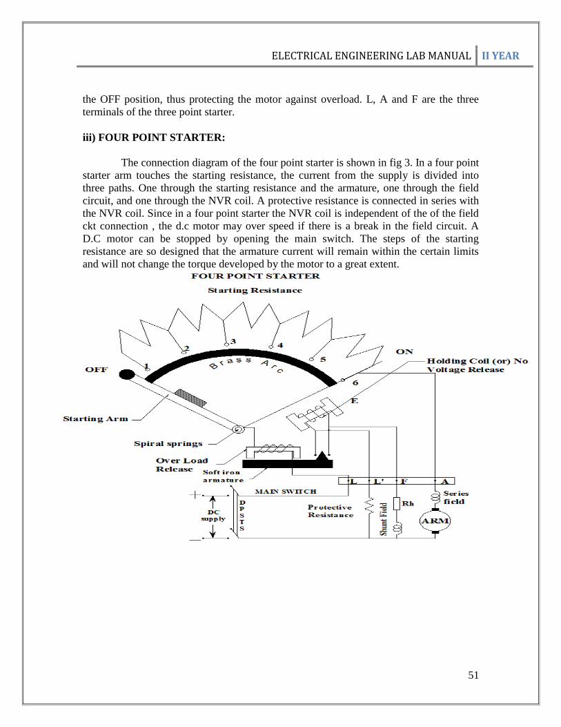
iii) FOUR POINT STARTER:
The connection diagram of the four point starter is shown in fig 3. In a four point
starter arm touches the starting resistance, the current from the supply is divided into
three paths. One through the starting resistance and the armature, one through the field
circuit, and one through the NVR coil. A protective resistance is connected in series with
the NVR coil. Since in a four point starter the NVR coil is independent of the of the field
ckt connection , the d.c motor may over speed if there is a break in the field circuit. A
D.C motor can be stopped by opening the main switch. The steps of the starting
resistance are so designed that the armature current will remain within the certain limits
and will not change the torque developed by the motor to a great extent.
ELECTRICAL ENGINEERING LAB MANUAL II YEAR
52
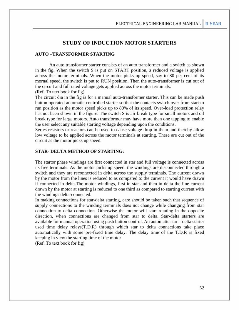
STUDY OF INDUCTION MOTOR STARTERS
AUTO –TRANSFORMER STARTING
An auto transformer starter consists of an auto transformer and a switch as shown
in the fig. When the switch S is put on START position, a reduced voltage is applied
across the motor terminals. When the motor picks up speed, say to 80 per cent of its
mornal speed, the switch is put to RUN position. Then the auto-transformer is cut out of
the circuit and full rated voltage gets applied across the motor terminals.
(Ref. To text book for fig)
The circuit dia in the fig is for a manual auto-transformer starter. This can be made push
button operated automatic controlled starter so that the contacts switch over from start to
run position as the motor speed picks up to 80% of its speed. Over-load protection relay
has not been shown in the figure. The switch S is air-break type for small motors and oil
break type for large motors. Auto transformer may have more than one tapping to enable
the user select any suitable starting voltage depending upon the conditions.
Series resistors or reactors can be used to cause voltage drop in them and thereby allow
low voltage to be applied across the motor terminals at starting. These are cut out of the
circuit as the motor picks up speed.
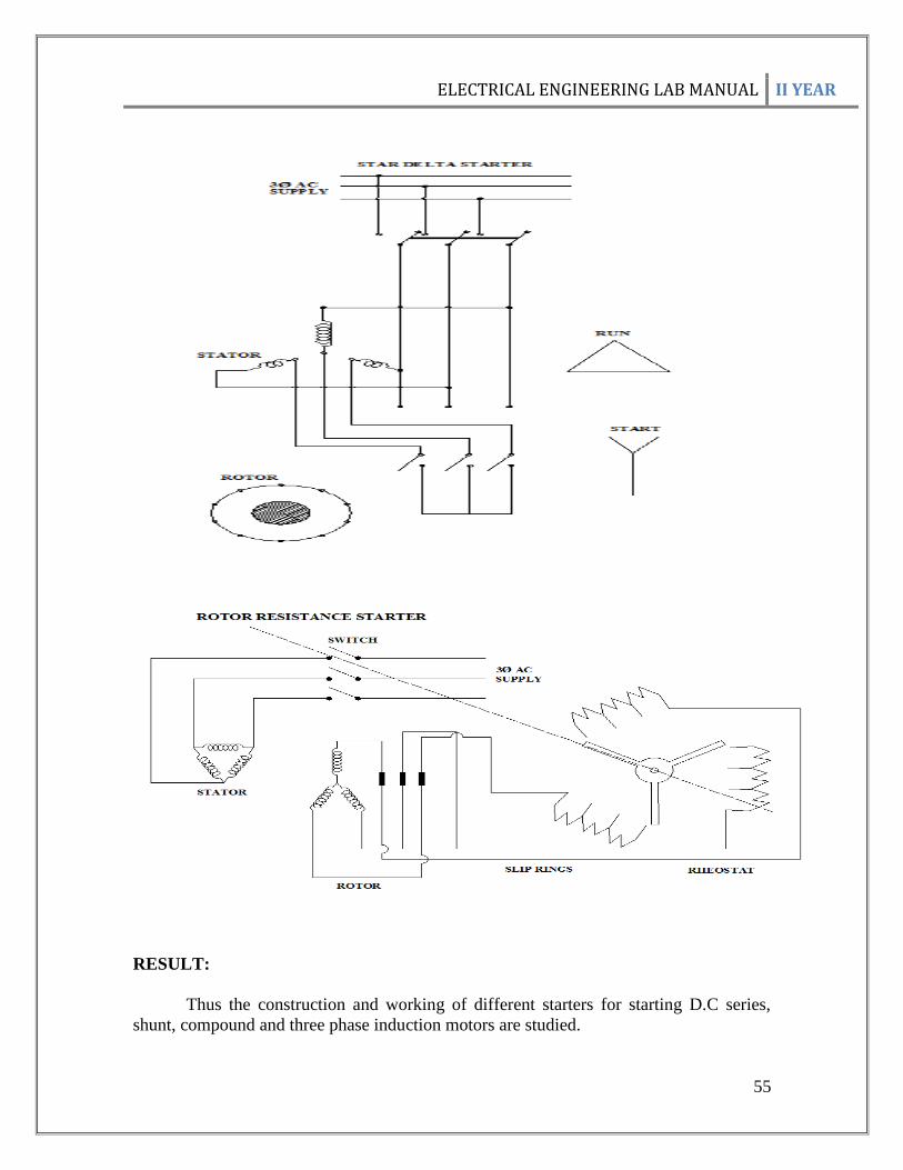
STAR- DELTA METHOD OF STARTING:
The startor phase windings are first connected in star and full voltage is connected across
its free terminals. As the motor picks up speed, the windings are disconnected through a
switch and they are reconnected in delta across the supply terminals. The current drawn
by the motor from the lines is reduced to as compared to the current it would have drawn
if connected in delta.The motor windings, first in star and then in delta the line current
drawn by the motor at starting is reduced to one third as compared to starting current with
the windings delta-connected.
In making connections for star-delta starting, care should be taken such that sequence of
supply connections to the winding terminals does not change while changing from star
connection to delta connection. Otherwise the motor will start rotating in the opposite
direction, when connections are changed from star to delta. Star-delta starters are
available for manual operation using push button control. An automatic star – delta starter
used time delay relays(T.D.R) through which star to delta connections take place
automatically with some pre-fixed time delay. The delay time of the T.D.R is fixed
keeping in view the starting time of the motor.
(Ref. To text book for fig)

ELECTRICAL ENGINEERING LAB MANUAL II YEAR
53
FULL VOLTAGE OR DIRECT –ON-LINE STARTING
When full voltage is connected across the stator terminals of an induction motor,
large current is drawn by the windings. This is because, at starting the induction motor
behaves as a short circuited transformer with its secondary, i.e. the rotor separated from
the primary, i.e. the stator by a small air-gap.
At starting when the rotor is at standstill, emf is induced in the rotor circuit
exactly similar to the emf induced in the secondary winding of a transformer. This
induced emf of the rotor will circulate a very large current through its windings. The
primary will draw very large current from the supply mains to balance the rotor ampere-
turns. To limit the stator and rotor currents at starting to a safe value, it may be necessary
to reduce the stator supply voltage to a low value. If induction motors are started direct-
on-line such a heavy starting current of short duration may not cause harm to the motor
since the construction of induction motors are rugged. Other motors and equipment
connected to the supply lines will receive reduced voltage. In industrial installations,
however, if a number of large motors are started by this method, the voltage drop will be
very high and may be really objectionable for the other types of loads connected to the
system. The amount of voltage drop will not only be dependent on the size of the motor
but also on factors like the capacity of the power supply system, the size and length of the
line leading to the motors etc. Indian Electricity Rule restricts direct on line starting of 3
phase induction motors above 5 hp.

ELECTRICAL ENGINEERING LAB MANUAL II YEAR
54
ELECTRICAL ENGINEERING LAB MANUAL II YEAR
55
RESULT:
Thus the construction and working of different starters for starting D.C series,
shunt, compound and three phase induction motors are studied.

ELECTRICAL ENGINEERING LAB MANUAL II YEAR
56
VIVA questions for the Experiments
1) LOAD TEST ON DC SHUNT AND SERIES MOTORS
1. What is the need for a starter?
2. Name the different types of starters for DC motors.
3. Why a DC shunt motor is called a constant Speed motor?
4. State few applications of DC shunt series motor.
5. What is the role of commutator in a DC motor?
6. What is the effect of armature reaction on the performance of DC motor?
7. What happen when the field circuit gets opened when a DC shunt motor is running?
8. How to reverse the direction of rotation of DC motor?
9. Explain why D.C series motor are started under no load.
2) OPEN CIRCUIT CHARACTERISTICS OF SELF EXCITED
DC SHUNT GENERATOR
1. Define critical field resistance and critical speed.
2. State the conditions to be satisfied by a DC shunt generator to build-up voltage.
3. What is residual flux and what happens to the generator induces EMF when residual
flux is zero?
4. What is the purpose of SPST switch connected in the field circuit of the generator?
5. Why the speed must be maintained constant throughout the experiment?
LOAD TEST ON SELF EXCITED DC SHUNT GENERATOR
1. What is a prime mover?
2. Why the speed of generator should be maintained constant during the experiment?
3. Why does the terminal voltage fall as the load on the generator is increased?
4. What is armature reaction and what are its effects on the performance of DC
generator?
3) SPEED CONTROL OF DC SHUNT MOTOR
1. Which method of speed control is used for controlling the speed of the motor above its
rated speed? Give reason.
2. Which method of speed control is used for controlling the speed of the motor below its
rated speed? Give reason.
3. Explain the reasons for the shape of the graphs obtained.
4. State any method to control the speed of a D.C series motor?
4) LOAD TEST ON A SINGLE PHASE TRANSFORMER
1. Define Regulation of a Transformer.
2. What is the effect of load p.f on regulation of Transformer?
3. What is the condition for maximum efficiency?
4. Determine the percentage load at which maximum efficiency occurred for the given
single-phase transformer?
5. What is the effect of change in frequency on the efficiency of the transformer?

ELECTRICAL ENGINEERING LAB MANUAL II YEAR
57
5) O.C AND S.C TESTS ON A SINGLE PHASE TRANSFORMER
1. Why O.C test is conducted on the L.V side and S.C test on the H.V side?
2. Define regulation in a transformer.
3. Why the regulation graph is not passing through the origin?
4. State the condition for maximum efficiency?
5. What is the regulation of an Ideal transformer?
6. What is the condition for maximum efficiency of a transformer?
6) PREDETERMINATION OF REGULATION BY EMF& MMF METHOD
1. Define regulation.
2. What is meant by pessimistic method?
3. Which method is called as optimistic method?
4. What are the advantages of EMF and MMF method?
5. Name some other methods used to predetermine the regulation.
7) V & INVERTED V CURVES ON 3 PHASE SYNCHRONOUS MOTOR
1) How will you start a synchronous motor?
2) What are the uses of Damper windings?
3) What is meant my synchronization?
4) Define pull in torque.
5) Define pull out torque.
6) Define synchronous speed.
8) LOAD TEST ON SQUIRREL CAGE INDUCTION MOTOR
1) What is squirrel cage induction motor?
2) What is the normal range of no load current of an induction motor?
3) Distinguish between rotating transformer and static transformer?
4) Define slip.
5) Draw the torque- slip Characteristics of an Induction motor.
9) SPPED CONTROL OF 3 PHASE SLIP RING INDUCTION MOTOR
1) What is meant by slip ring?
2) What are the different methods of seed control in slip ring induction motor?
3) What are the advantages of using rotor resistance starter?
4) Explain the basic speed control equation of a.c machines.
5) Compare squirrel cage motors with slip ring motors.

ELECTRICAL ENGINEERING LAB MANUAL II YEAR
58
10) LOAD TEST ON SINGLE PHASE INDUCTION MOTOR
VIVA QUESTIONS:
1. What are the different types of single phase induction motors?
2. Explain why single phase induction motors are not self-starting?
3. Draw the phasor diagrams of Single phase induction motor indicating the starting
winding and running winding current components.
4. Define slip.
5. List out the applications of Single Phase induction motors.
11) STUDY OF D.C MOTOR STARTERS
VIVA QUESTIONS:
1. Differentiate two point and three point starter
2. What is the need for starter in electrical technology?
3. Differentiate four point and three point starter
4. What are the types of starter?
5. What are the protective devices used in starters?
STUDY OF INDUCTION MOTOR STARTERS
VIVA QUESTIONS:
1. Differentiate star – delta and auto transformer starter
2. What is the need for starter in electrical technology?
3. Differentiate auto transformer and DOL starter
4. What are the types of AC starters?
5. What are the protective features used in starters?

ELECTRICAL ENGINEERING LAB MANUAL II YEAR
59
Introduction to Experiments
(1) LOAD TEST ON DC SHUNT & SERIES MOTORS
INTRODUCTION
D.C motor converts electrical energy into mechanical energy (rotational) with the
help of the excitation.
In this experiment the effect of mechanical loading on torque, speed, Output
power, line current and efficiency can be understood
(2) OPEN CIRCUIT CHARACTERISTICS OF SELF EXCITED
DC SHUNT GENERATOR
INTRODUCTION
In this experiment D.C motor acts as prime mover supplying mechanical energy
which is converted into electrical energy by the D.C shunt generator, with the help of
field system of generator
Open circuit characteristics give the relation between the excitation and generated
voltage (e.m.f). Role of residual flux, critical resistance and voltage building up processes
can be understood by this experiment.
LOAD TEST ON SELF EXCITED DC SHUNT GENERATOR
INTRODUCTION
In this experiment, the effect of armature resistance and armature reaction can be
understood. Internal characteristics explain the effect of armature reaction and external
characteristics help in understanding the effect of armature resistive voltage drop in
addition to armature reaction.
(3) SPEED CONTROL OF DC SHUNT MOTOR
INTRODUCTION
This experiment helps in understanding
(1) the effect of back e.m.f on speed, at constant excitation(Armature control
method)
(2) the effect of field current( before saturation) on speed, at consant armature
voltage(Field control method)
(4) LOAD TEST ON A SINGLE PHASE TRANSFORMER
INTRODUCTION
This experiment helps in understanding the performance of single phase
transformer, which is an electromagnetic device working on the principle of
electromagnetic induction (Statically induced e.m.f which is on the self and mutual
induction basis.)
(5) O.C AND S.C TESTS ON A SINGLE PHASE TRANSFORMER

ELECTRICAL ENGINEERING LAB MANUAL II YEAR
60
INTRODUCTION
Open circuit test is helpful in measuring the core losses (constant losses).
Short circuit test is useful in measuring the copper losses (electrical losses) at
rated load condition.
With the help of these tests and measurements, the performance of the
transformer at different load conditions can be predetermined.
(6) PREDETERMINATION OF REGULATION BY EMFAND MMF METHOD
INTRODUCTION
Armature resistance measurement, Open circuit and short circuit tests are
conducted on alternators/synchronous generators to estimate the resistance, impedance
and reactance per phase of the armature winding.
Open circuit test is helpful in measuring the core losses (constant losses).
Short circuit test is useful in measuring the copper losses (electrical losses) at
rated load condition.
With the help of these tests, characteristic curves and measurements, the
performance of the alternator/synchronous generator, at different load conditions can be
predetermined.
7) V AND INVERTED V CURVES OF THREE PHASE SYNCHRONOUS
MOTOR
INTRODUCTION
Initially the motor starts as induction motor with the help of damper winding and
with the field kept open.
When the speed approaches near synchronous speed, the motor field is excited
and thus the motor is brought into magnetic locking.
V Curves explain the relationship between field current and armature current
Inverted v curves explain the relationship between field current and power factor
of the motor circuit.
(8) LOAD TEST ON SQUIRREL CAGE INDUCTION MOTOR
INTRODUCTION Induction motor converts electrical energy into mechanical energy(rotational)
(supply provided to the stator winding itself acts as excitation /aiding mechanism, as per
Lenz law and Faraday’s laws of electromagnetic induction)
In this experiment the effect of mechanical loading on torque, speed, output
power, power factor, line current and efficiency can be understood.

ELECTRICAL ENGINEERING LAB MANUAL II YEAR
61
(9) SPEED CONTROL OF THREE PHASE SLIP RING INDUCTION MOTOR
INTRODUCTION
Induction motor speed control can be done from stator and rotor side.
In the stator side control methods either the net voltage fed into the stator winding
is controlled or its frequency is varied to operate the machine at different speeds.
In case of Slip ring Induction motor, rotor side effective resistance can be
controlled through external rotor resistors or through rotor resistance starter and thus, the
speed and slip of the motor can be controlled.
10) LOAD TEST ON SINGLE PHASE (CAPACITOR START INDUCTION) RUN
INDUCTION MOTOR
INTRODUCTION Induction motor converts electrical energy into mechanical energy(rotational)
(supply provided to the stator winding itself acts as excitation /aiding mechanism, as per
Lenz law and Faraday’s laws of electromagnetic induction).
Single phase induction motors are not self-starting and a revolving double field
arrangement effected with the help of (starting winding + main Winding steup) is
used to start the motor.
In this experiment, the effect of mechanical loading on torque, speed, output
power, power factor, line current and efficiency can be understood.
(11) STUDY OF D.C MOTOR STARTERS
INTRODUCTION
This study is helpful in understanding the performance of starter and its salient
features like no voltage/over load protection circuitry.
STUDY OF INDUCTION MOTOR STARTERS
INTRODUCTION
This study is helpful in understanding the performance of starter and its salient
features like no voltage/over load protection circuitry, thermal over load protection etc. in
addition to starting torque developments and starting current limitations.
*********************************************************************