Embed Size (px)
Citation preview
Ann and Alison Fields
Decommissioning Programmes
Ann and Alison Fields Decommissioning Programmes Page 2
REVISION RECORD
Revision No. Date of Revision Reason
A1 17/03/17 Issued for internal review and comment
A2 07/04/17 Issued to BEIS for comment
A3 17/05/17 BEIS comments addressed
A4 20/06/17 Additional comments addressed
A5 23/06/17 Issued for Statutory Consultation
Distribution List
Company or Organisation No of Copies
Department for Business, Energy, & Industrial Strategy 1 electronic
GMS, NIFPO, NFFO, SFF 1 each, electronic
Great Yarmouth Community Library 1 hardcopy
Ann and Alison Fields Decommissioning Programmes Page 3
TABLE OF CONTENTS INST P/L
1 Executive Summary 8
1.1 Combined Decommissioning Programmes 8
1.2 Requirement for Decommissioning Programmes 8
1.3 Introduction 8
1.4 Ann Field – Decommissioning Overview 10
1.5 Alison Field – Decommissioning Overview 11
1.6 Summary of Proposed Decommissioning Programmes 12
1.7 Field Location Including Field Layout and Adjacent Facilities 13
1.8 Industrial Implications 21
2 Description of Items to be Decommissioned 22
2.1 Ann Field 22
2.2 Alison Field 28
3 Removal and Disposal Methods 32
3.1 Topsides 32
3.2 Jacket(s) 32
3.3 Subsea Installations and Stabilisation Features 32
3.4 Pipelines 32
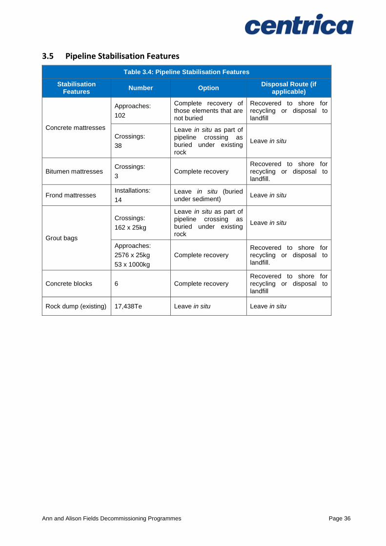
3.5 Pipeline Stabilisation Features 36
3.6 Wells 38
3.7 Drill Cuttings 39
3.8 Waste Streams 39
4 Environmental Impact Assessment 41
4.1 Environmental Sensitivities 41
4.2 Potential Environmental Impacts and their Management 44
5 Interested Party Consultations 46
5.1 Consultations Summary 46
6 Programme Management 48
6.1 Project Management and Verification 48
6.2 Post-Decommissioning Debris Clearance and Verification 48
6.3 Schedule 48
6.4 Costs 49
6.5 Close Out 49
6.6 Post-Decommissioning Monitoring and Evaluation 49
7 Supporting Documents 50
Ann and Alison Fields Decommissioning Programmes Page 4
FIGURES AND TABLES
Figure 1.1: Field Location in UKCS ............................................................................................ 13
Figure 1.2: Ann & Alison Adjacent Facilities ............................................................................... 14
Figure 1.3: Overview of Ann Pipeline Approaches ...................................................................... 15
Figure 1.4: Overview of Alison Pipeline Approaches .................................................................. 15
Figure 1.5: Overview of Audrey B (XW) Pipeline Approaches..................................................... 16
Figure 1.6: PL947 Pipeline Approach at LOGGS ........................................................................ 16
Figure 1.7: Adjacent Facilities..................................................................................................... 20
Figure 2.1: Pie-Chart of estimated inventories (Ann installation) ................................................. 26
Figure 2.2: Pie-Chart of estimated inventories (Ann pipelines) excl. rock ................................... 27
Figure 2.3: Pie-Chart of estimated inventories (Ann pipelines) incl. rock .................................... 27
Figure 2.4: Pie-Chart of estimated inventories (Alison installation) ............................................. 30
Figure 2.5: Pie-Chart of estimated inventories (Alison pipeline) .................................................. 31
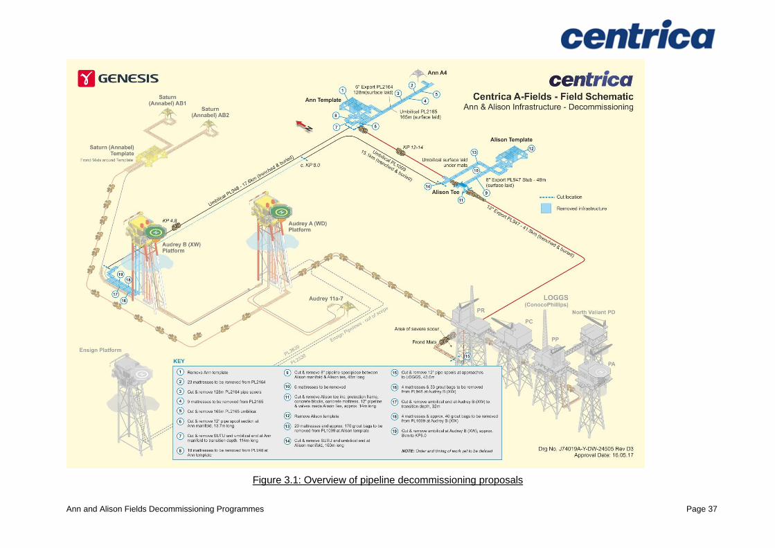
Figure 3.1: Overview of pipeline decommissioning proposals ..................................................... 37
Figure 6.1: Gantt Chart of Project Plan ....................................................................................... 48
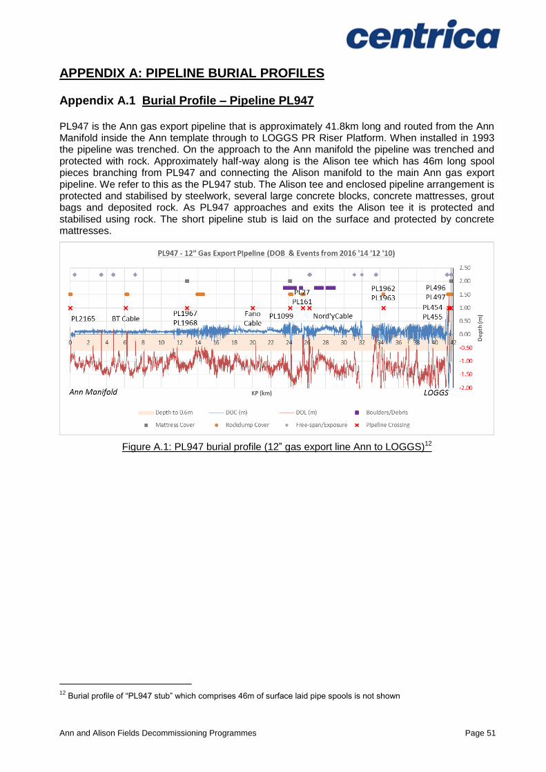
Figure A.1: PL947 burial profile (12” gas export line Ann to LOGGS) ......................................... 51
Figure A.2: PL948 burial profile (umbilical pipeline Audrey B (XW) to Ann) ................................ 52
Figure A.3: PL1099 burial profile (umbilical pipeline Audrey B (XW) to Alison) ........................... 53
Table 1.1: Installation Being Decommissioned ........................................................................... 10
Table 1.2: Installation Section 29 Notice Holders Details ............................................................ 10
Table 1.3: Pipelines Being Decommissioned .............................................................................. 10
Table 1.4: Pipelines Section 29 Notice Holders Details .............................................................. 10
Table 1.5: Installation Being Decommissioned ........................................................................... 11
Table 1.6: Installation Section 29 Notice Holders Details ............................................................ 11
Table 1.7: Pipeline Being Decommissioned................................................................................ 11
Table 1.8: Pipeline Section 29 Notice Holders Details ................................................................ 11
Table 1.9: Summary of Decommissioning Programmes ............................................................. 12
Table 1.10: Adjacent Facilities .................................................................................................... 17
Table 2.1: Surface Facilities Information ..................................................................................... 22
Table 2.2: Subsea Installations and Stabilisation Features ......................................................... 22
Table 2.3: Pipeline/Flowline/Umbilical Information ...................................................................... 23
Table 2.4: Subsea Pipeline Stabilisation Features ...................................................................... 24
Table 2.5: Well Information ......................................................................................................... 26
Table 2.6: Drill Cuttings Pile(s) Information................................................................................. 26
Table 2.7: Surface Facilities Information ..................................................................................... 28
Table 2.8: Subsea Installations and Stabilisation Features ......................................................... 28
Table 2.9: Pipeline/Flowline/Umbilical Information ...................................................................... 29
Table 2.10: Subsea Pipeline Stabilisation Features .................................................................... 29
Table 2.11: Well Information ....................................................................................................... 30
Table 2.12: Drill Cuttings Pile(s) Information ............................................................................... 30
Table 3.1: Subsea Installations and Stabilisation Features ......................................................... 32
Table 3.2: Pipeline Decommissioning Options ............................................................................ 33
Table 3.3: Outcomes of the Comparative Assessment ............................................................... 34
Ann and Alison Fields Decommissioning Programmes Page 5
Table 3.4: Pipeline Stabilisation Features ................................................................................... 36
Table 3.5: Well Plug and Abandonment ..................................................................................... 38
Table 3.6: Waste Stream Management Methods ........................................................................ 39
Table 3.7: Inventory Disposition ................................................................................................. 39
Table 3.8: Re-use, Recycle & Disposal Aspirations for Material Recovered to Shore ................. 40
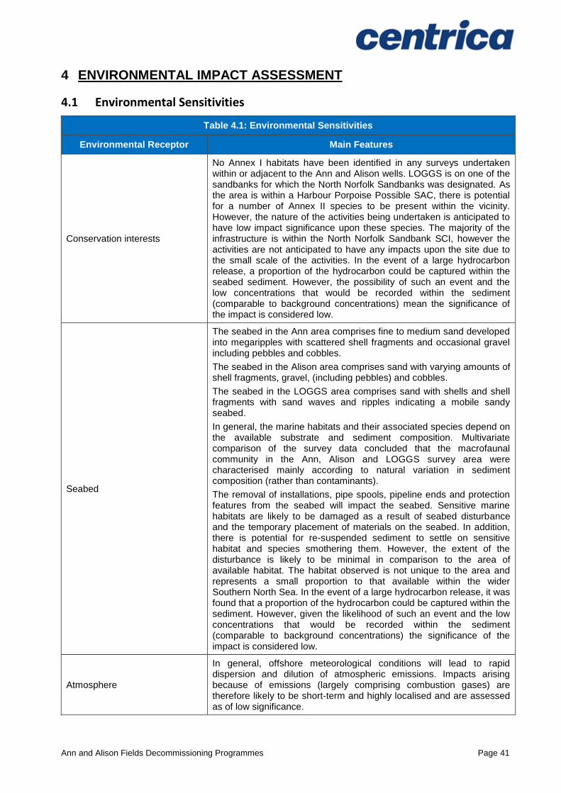
Table 4.1: Environmental Sensitivities ........................................................................................ 41
Table 4.2: Environmental Impact Management .......................................................................... 44
Table 5.1: Summary of Stakeholder Comments ......................................................................... 46
Table 6.1: Provisional Decommissioning Programme Costs ....................................................... 49
Table 7.1: Supporting Documents .............................................................................................. 50
TABLE OF APPENDICES
Appendix Description Page
A Pipeline Trenching/Burial Profile Graphs 51-53
B Public Notice & Consultee Correspondence – HOLD tba
Ann and Alison Fields Decommissioning Programmes Page 6
TERMS AND ABBREVIATIONS
ABBREVIATION EXPLANATION
Ann A4 Single subsea well (A4z) tied back to Ann manifold
Ann Installation Ann template. The Ann manifold is located inside and protected by the template structure
Alison Installation Alison template. The Alison manifold is located inside and protected by the template structure
Alison tee piece Alison product was exported through the main Ann export system (PL947) via spool pieces which are tied into a tee piece on (PL947), the tee piece is protected by a steel frame, concrete blocks and concrete mats
Approach Initial or final stretch of pipeline (or umbilical) as it leaves its point of origin or reaches its destination
BEIS Department for Business, Energy, and Industrial Strategy
Centrica Centrica North Sea Limited
CPUK ConocoPhillips (U.K.) Limited
Crossing Pipeline crossing. A higher pipeline number crosses over the top of a pipeline with a lower identification number, so for example, PL1099 crosses over PL947. Typically pipeline crossings might be protected with concrete mattresses and overlain with deposited rock
CSV Construction Support Vessel
DOB Depth of Burial
DOC(m) Depth of cover (depth of sediment above pipe)
DOL(m) Depth of Lowering (depth to top of pipe from adjacent seabed)
DSV Diving Support Vessel
GE Gas Export
HSE Health and Safety Executive
" Inch, 25.4millimetres
ITT Invitation to Tender
JNCC Joint Nature Conservation Committee
km Kilometre
LOGGS Lincolnshire Offshore Gas Gathering System
m Metre
MAT Master Application Template
MEG Monoethylene glycol
mm Million
n/a Not applicable
NFFO National Federation of Fishermen's Organisations
NIFPO Northern Ireland Fish Producers Organisation
NORM Naturally Occurring Radioactive Material
NUI Normally Unattended Installation
OGA Oil & Gas Authority
OSPAR Oslo Paris Convention
P&A Plug and Abandonment
PON Petroleum Operations Notice
PR (LOGGS) PR Riser Platform
Ann and Alison Fields Decommissioning Programmes Page 7
ABBREVIATION EXPLANATION
PWA Pipeline Works Authorisation
SAT Subsidiary Application Template
SCI Site(s) of Community Importance
SFF Scottish Fishermen’s Federation
SNS Southern North Sea
SSW South South West
SUTU Subsea Umbilical Termination Unit
tba To be announced
Te Tonne
UKCS United Kingdom Continental Shelf
WGS84 World Geodetic System 1984
WHPS Wellhead Protection Structure
Ann and Alison Fields Decommissioning Programmes Page 8
1 EXECUTIVE SUMMARY
1.1 Combined Decommissioning Programmes
This document contains four Decommissioning Programmes, one for each set of notices served under Section 29 of the Petroleum Act 1998. The Decommissioning Programmes are:
The Ann installation (a wellhead template protection structure);
The four associated pipelines;
The Alison installation (a wellhead template protection structure);
The one associated pipeline.
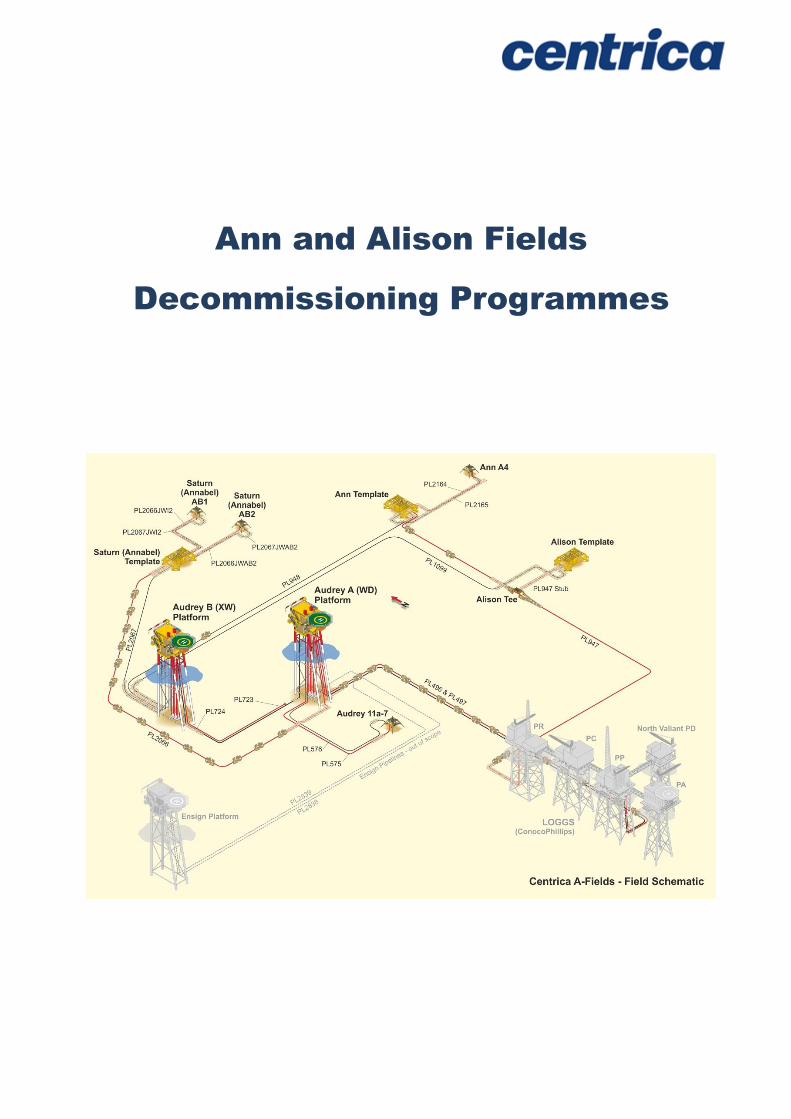
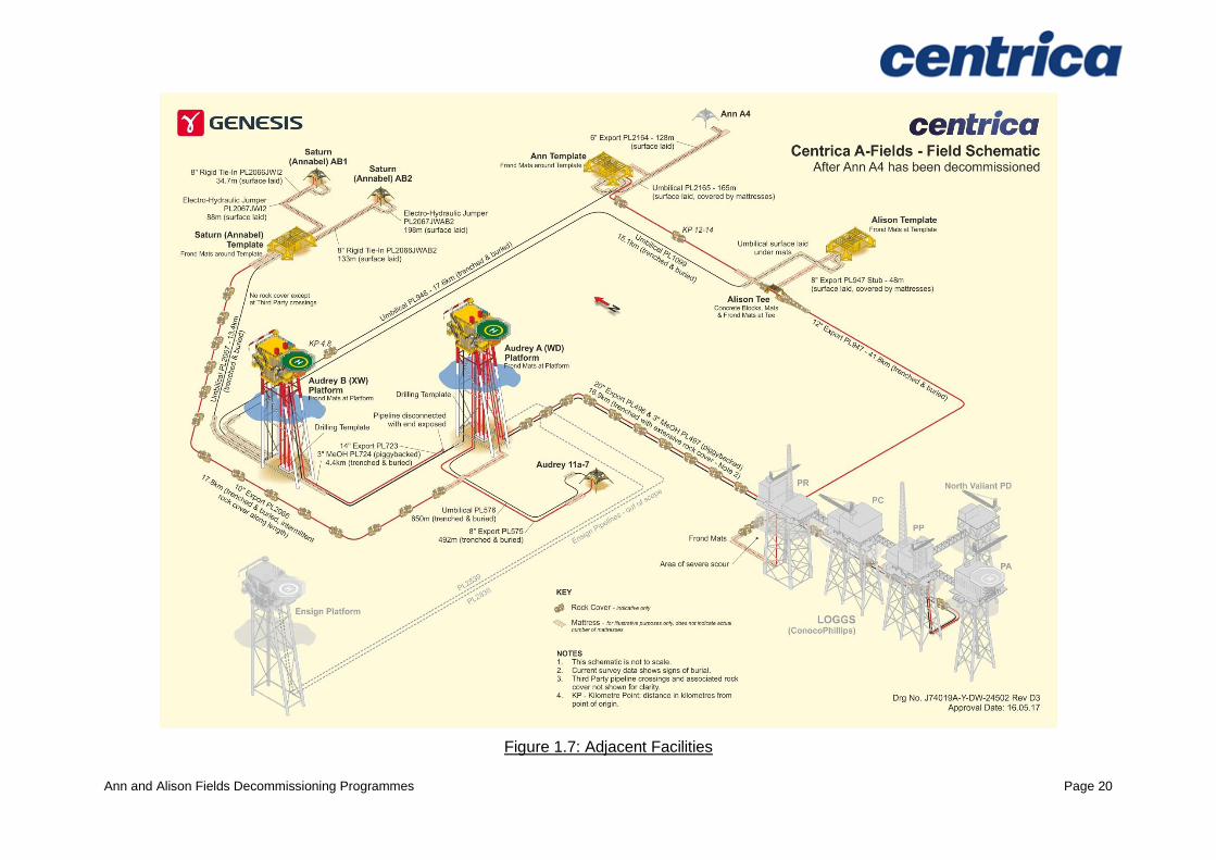
Although decommissioning of the Ann and Alison installations and pipelines is being treated in this document as a standalone project, the operational phase is being carried out as part of a wider decommissioning campaign in the A Fields area (see Figure 1.7). We will also continue to explore cost saving synergies with other projects.
1.2 Requirement for Decommissioning Programmes
Installations: In accordance with the Petroleum Act 1998, the Section 29 notice holders of the Ann and Alison installations/fields (see Table 1.2 and Table 1.6) are applying to the Department for Business, Energy and Industrial Strategy (BEIS) to obtain approval for decommissioning the installations detailed in Sections 2.1.1, 2.1.2, 2.2.1 and 2.2.2 of this document.
Pipelines: In accordance with the Petroleum Act 1998, the Section 29 notice holders of the Ann and Alison pipelines (see Table 1.4 and Table 1.8) are applying to the Department for Business, Energy and Industrial Strategy to obtain approval for decommissioning the pipelines detailed in Sections 2.1.3 and 2.2.3 of this document.
In conjunction with public, stakeholder and regulatory consultation, the Decommissioning Programmes are submitted in compliance with national and international regulations and BEIS Guidance Notes.
The schedule outlined in this document is for a seven year decommissioning project plan with well abandonment activities due to begin in 2017.
1.3 Introduction
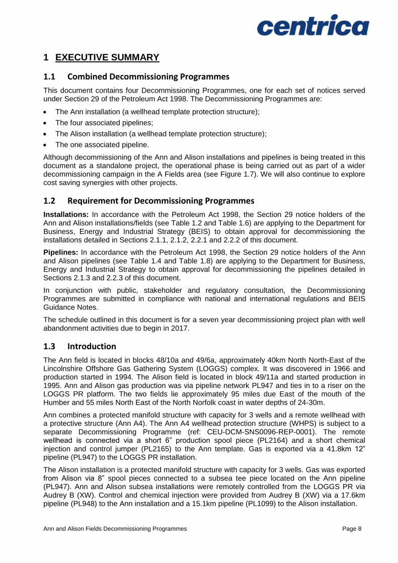
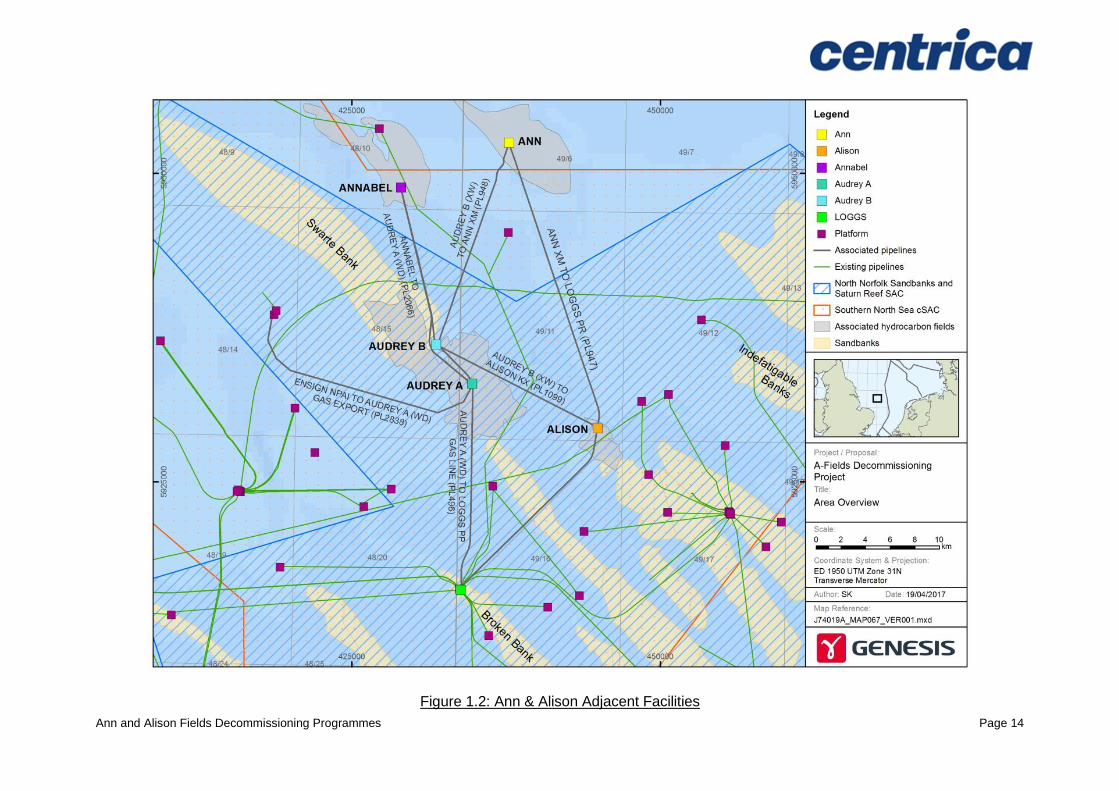
The Ann field is located in blocks 48/10a and 49/6a, approximately 40km North North-East of the Lincolnshire Offshore Gas Gathering System (LOGGS) complex. It was discovered in 1966 and production started in 1994. The Alison field is located in block 49/11a and started production in 1995. Ann and Alison gas production was via pipeline network PL947 and ties in to a riser on the LOGGS PR platform. The two fields lie approximately 95 miles due East of the mouth of the Humber and 55 miles North East of the North Norfolk coast in water depths of 24-30m.
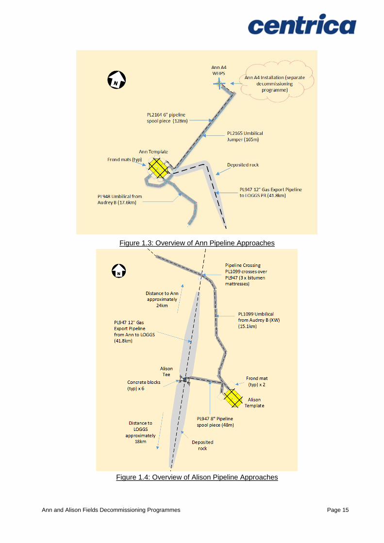
Ann combines a protected manifold structure with capacity for 3 wells and a remote wellhead with a protective structure (Ann A4). The Ann A4 wellhead protection structure (WHPS) is subject to a separate Decommissioning Programme (ref: CEU-DCM-SNS0096-REP-0001). The remote wellhead is connected via a short 6” production spool piece (PL2164) and a short chemical injection and control jumper (PL2165) to the Ann template. Gas is exported via a 41.8km 12” pipeline (PL947) to the LOGGS PR installation.
The Alison installation is a protected manifold structure with capacity for 3 wells. Gas was exported from Alison via 8” spool pieces connected to a subsea tee piece located on the Ann pipeline (PL947). Ann and Alison subsea installations were remotely controlled from the LOGGS PR via Audrey B (XW). Control and chemical injection were provided from Audrey B (XW) via a 17.6km pipeline (PL948) to the Ann installation and a 15.1km pipeline (PL1099) to the Alison installation.

Ann and Alison Fields Decommissioning Programmes Page 9
There has been no commercial flow from the Ann installation since September 2012. Production from Ann A4 was suspended in June 2009, and production from Alison was suspended in February 2010. Production through PL947 is suspended and the line contains process fluids (gas, condensate and water), methanol and corrosion inhibitor.
A cessation of production justification for Ann was approved by the Oil and Gas Authority (OGA) in December 2015, and for Alison in January 2016.
Following public, stakeholder and regulatory consultation, the Decommissioning Programmes will be submitted without derogation and in full compliance with the BEIS Guidance Notes. The Decommissioning Programmes explain the principles of the removal activities and are supported by an environmental impact assessment. The Decommissioning Programmes for the pipelines are also supported by a comparative assessment [2]. Decommissioning proposals for fronded mattresses are also supported by a comparative assessment [2].
Ann and Alison Fields Decommissioning Programmes Page 10
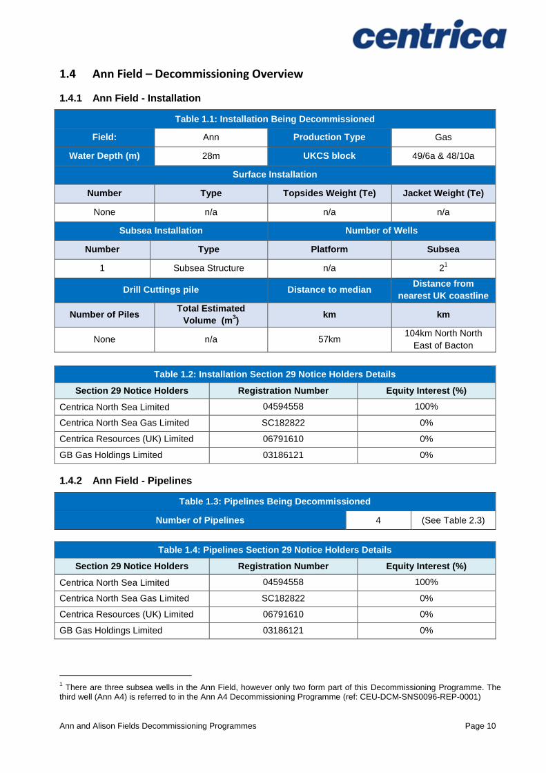
1.4 Ann Field – Decommissioning Overview
1.4.1 Ann Field - Installation
Table 1.1: Installation Being Decommissioned
Field: Ann Production Type Gas
Water Depth (m) 28m UKCS block 49/6a & 48/10a
Surface Installation
Number Type Topsides Weight (Te) Jacket Weight (Te)
None n/a n/a n/a
Subsea Installation Number of Wells
Number Type Platform Subsea
1 Subsea Structure n/a 21
Drill Cuttings pile Distance to median Distance from
nearest UK coastline
Number of Piles Total Estimated
Volume (m3)
km km
None n/a 57km 104km North North
East of Bacton
Table 1.2: Installation Section 29 Notice Holders Details
Section 29 Notice Holders Registration Number Equity Interest (%)
Centrica North Sea Limited 04594558 100%
Centrica North Sea Gas Limited SC182822 0%
Centrica Resources (UK) Limited 06791610 0%
GB Gas Holdings Limited 03186121 0%
1.4.2 Ann Field - Pipelines
Table 1.3: Pipelines Being Decommissioned
Number of Pipelines 4 (See Table 2.3)
Table 1.4: Pipelines Section 29 Notice Holders Details
Section 29 Notice Holders Registration Number Equity Interest (%)
Centrica North Sea Limited 04594558 100%
Centrica North Sea Gas Limited SC182822 0%
Centrica Resources (UK) Limited 06791610 0%
GB Gas Holdings Limited 03186121 0%
1 There are three subsea wells in the Ann Field, however only two form part of this Decommissioning Programme. The
third well (Ann A4) is referred to in the Ann A4 Decommissioning Programme (ref: CEU-DCM-SNS0096-REP-0001)
Ann and Alison Fields Decommissioning Programmes Page 11
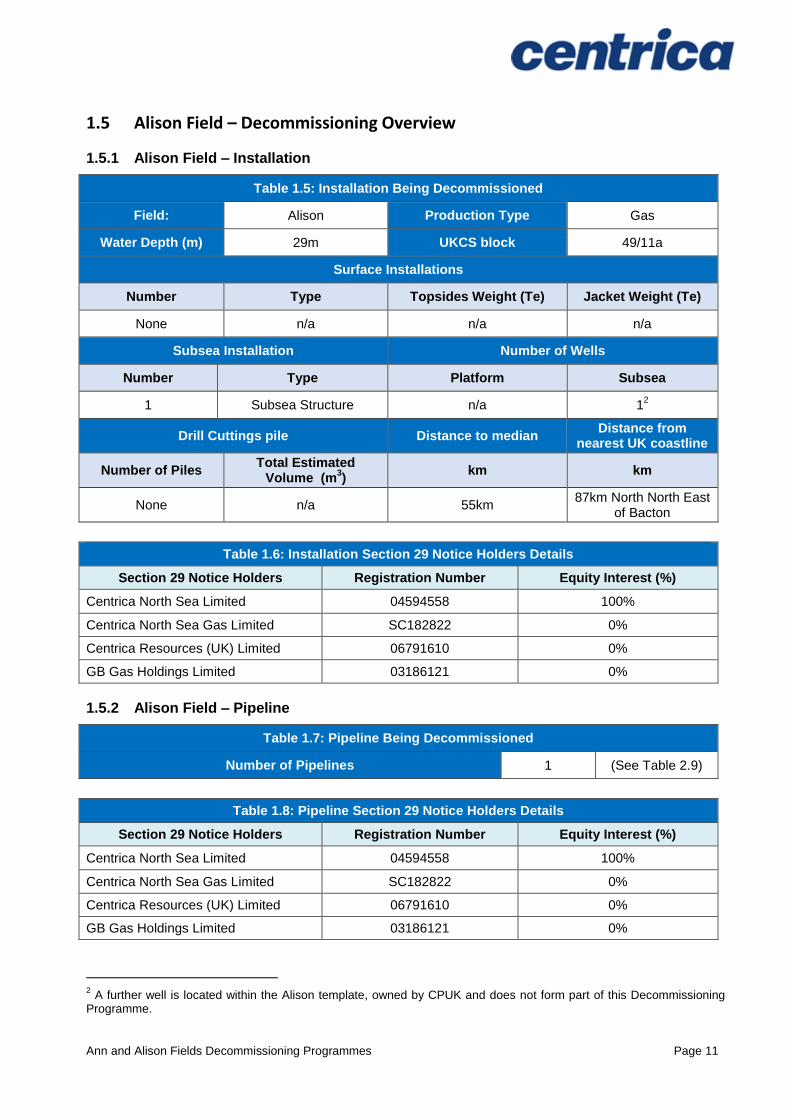
1.5 Alison Field – Decommissioning Overview
1.5.1 Alison Field – Installation
Table 1.5: Installation Being Decommissioned
Field: Alison Production Type Gas
Water Depth (m) 29m UKCS block 49/11a
Surface Installations
Number Type Topsides Weight (Te) Jacket Weight (Te)
None n/a n/a n/a
Subsea Installation Number of Wells
Number Type Platform Subsea
1 Subsea Structure n/a 12
Drill Cuttings pile Distance to median Distance from
nearest UK coastline
Number of Piles Total Estimated
Volume (m3)
km km
None n/a 55km 87km North North East
of Bacton
Table 1.6: Installation Section 29 Notice Holders Details
Section 29 Notice Holders Registration Number Equity Interest (%)
Centrica North Sea Limited 04594558 100%
Centrica North Sea Gas Limited SC182822 0%
Centrica Resources (UK) Limited 06791610 0%
GB Gas Holdings Limited 03186121 0%
1.5.2 Alison Field – Pipeline
Table 1.7: Pipeline Being Decommissioned
Number of Pipelines 1 (See Table 2.9)
Table 1.8: Pipeline Section 29 Notice Holders Details
Section 29 Notice Holders Registration Number Equity Interest (%)
Centrica North Sea Limited 04594558 100%
Centrica North Sea Gas Limited SC182822 0%
Centrica Resources (UK) Limited 06791610 0%
GB Gas Holdings Limited 03186121 0%
2 A further well is located within the Alison template, owned by CPUK and does not form part of this Decommissioning
Programme.
Ann and Alison Fields Decommissioning Programmes Page 12
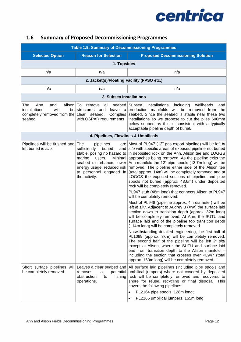
1.6 Summary of Proposed Decommissioning Programmes
Table 1.9: Summary of Decommissioning Programmes
Selected Option Reason for Selection Proposed Decommissioning Solution
1. Topsides
n/a n/a n/a
2. Jacket(s)/Floating Facility (FPSO etc.)
n/a n/a n/a
3. Subsea Installations
The Ann and Alison installations will be completely removed from the seabed.
To remove all seabed structures and leave a clear seabed. Complies with OSPAR requirements
Subsea installations including wellheads and production manifolds will be removed from the seabed. Since the seabed is stable near these two installations so we propose to cut the piles 600mm below seabed as this is consistent with a typically acceptable pipeline depth of burial.
4. Pipelines, Flowlines & Umbilicals
Pipelines will be flushed and left buried in situ.
The pipelines are sufficiently buried and stable, posing no hazard to marine users. Minimal seabed disturbance, lower energy usage, reduced risk to personnel engaged in the activity.
Most of PL947 (12” gas export pipeline) will be left in situ with specific areas of exposed pipeline not buried in deposited rock on the Ann, Alison tee and LOGGS approaches being removed. As the pipeline exits the Ann manifold the 12” pipe spools (13.7m long) will be removed. The pipeline either side of the Alison tee (total approx. 14m) will be completely removed and at LOGGS the exposed sections of pipeline and pipe spools not buried (approx. 43.6m) under deposited rock will be completely removed.
PL947 stub (48m long) that connects Alison to PL947 will be completely removed.
Most of PL948 (pipeline approx. 4in diameter) will be left in situ. Adjacent to Audrey B (XW) the surface laid section down to transition depth (approx. 32m long) will be completely removed. At Ann, the SUTU and surface laid end of the pipeline top transition depth (114m long) will be completely removed.
Notwithstanding detailed engineering, the first half of PL1099 (approx. 8km) will be completely removed. The second half of the pipeline will be left in situ except at Alison, where the SUTU and surface laid end from transition depth to the Alison manifold – including the section that crosses over PL947 (total approx. 160m long) will be completely removed.
Short surface pipelines will be completely removed.
Leaves a clear seabed and removes a potential obstruction to fishing operations.
All surface laid pipelines (including pipe spools and umbilical jumpers) where not covered by deposited rock will be completely removed and recovered to shore for reuse, recycling or final disposal. This covers the following pipelines:
PL2164 pipe spools, 128m long;
PL2165 umbilical jumpers, 165m long.
Ann and Alison Fields Decommissioning Programmes Page 13
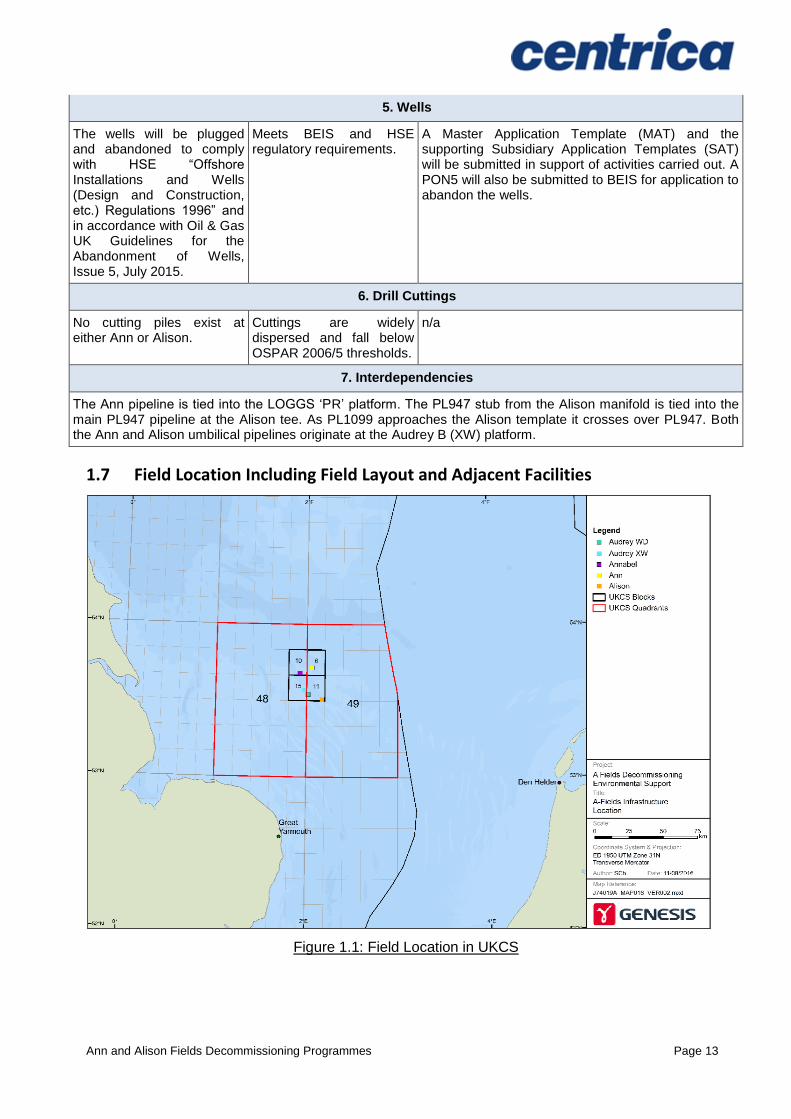
5. Wells
The wells will be plugged and abandoned to comply with HSE “Offshore Installations and Wells (Design and Construction, etc.) Regulations 1996” and in accordance with Oil & Gas UK Guidelines for the Abandonment of Wells, Issue 5, July 2015.
Meets BEIS and HSE regulatory requirements.
A Master Application Template (MAT) and the supporting Subsidiary Application Templates (SAT) will be submitted in support of activities carried out. A PON5 will also be submitted to BEIS for application to abandon the wells.
6. Drill Cuttings
No cutting piles exist at either Ann or Alison.
Cuttings are widely dispersed and fall below OSPAR 2006/5 thresholds.
n/a
7. Interdependencies
The Ann pipeline is tied into the LOGGS ‘PR’ platform. The PL947 stub from the Alison manifold is tied into the main PL947 pipeline at the Alison tee. As PL1099 approaches the Alison template it crosses over PL947. Both the Ann and Alison umbilical pipelines originate at the Audrey B (XW) platform.
1.7 Field Location Including Field Layout and Adjacent Facilities
Figure 1.1: Field Location in UKCS
Ann and Alison Fields Decommissioning Programmes Page 14
Figure 1.2: Ann & Alison Adjacent Facilities
Ann and Alison Fields Decommissioning Programmes Page 15
Figure 1.3: Overview of Ann Pipeline Approaches
Figure 1.4: Overview of Alison Pipeline Approaches

Ann and Alison Fields Decommissioning Programmes Page 16
Figure 1.5: Overview of Audrey B (XW) Pipeline Approaches
Figure 1.6: PL947 Pipeline Approach at LOGGS
PL1099 umbilical to Alison (15.1km)
PL948 umbilical to Ann (17.6km)
PL723 14" gas export pipeline to Audrey A (WD) (4.3km)
PL2067 umbilical to Annabel (13.4km)
AUDREY B (XW)PLATFORM 4 x concrete
mattresses
4 x concrete mattresses
grout bags
30 x concrete mattresses
grout bags
8 x concrete mattresses
PL724 3" methanol pipeline from Audrey A (WD) (4.4km)
9 x fronded mattresses buried
grout bags over and under PL723/4
To Annabel
grout bags over flexible 3" methanol line
To Ann
To Audrey A (WD)Platform
To Alison
Ann and Alison Fields Decommissioning Programmes Page 17
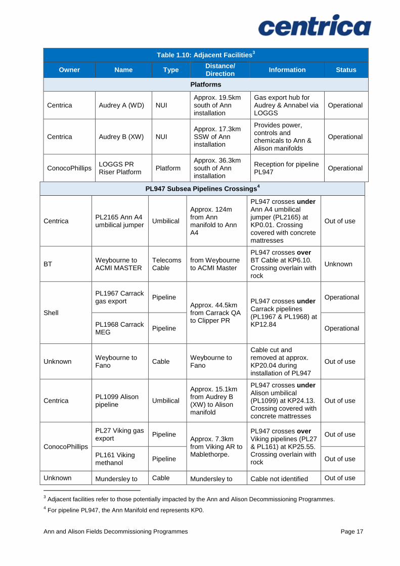
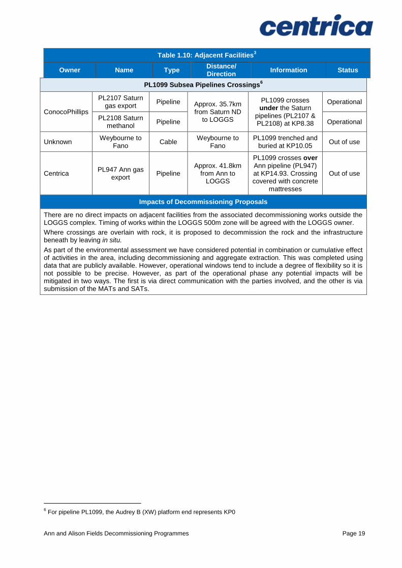
Table 1.10: Adjacent Facilities3
Owner Name Type Distance/ Direction
Information Status
Platforms
Centrica Audrey A (WD) NUI Approx. 19.5km south of Ann installation
Gas export hub for Audrey & Annabel via LOGGS
Operational
Centrica Audrey B (XW) NUI Approx. 17.3km SSW of Ann installation
Provides power, controls and chemicals to Ann & Alison manifolds
Operational
ConocoPhillips LOGGS PR Riser Platform
Platform Approx. 36.3km south of Ann installation
Reception for pipeline PL947
Operational
PL947 Subsea Pipelines Crossings4
Centrica PL2165 Ann A4 umbilical jumper
Umbilical
Approx. 124m from Ann manifold to Ann A4
PL947 crosses under Ann A4 umbilical jumper (PL2165) at KP0.01. Crossing covered with concrete mattresses
Out of use
BT Weybourne to ACMI MASTER
Telecoms Cable
from Weybourne to ACMI Master
PL947 crosses over BT Cable at KP6.10. Crossing overlain with rock
Unknown
Shell
PL1967 Carrack gas export
Pipeline Approx. 44.5km from Carrack QA to Clipper PR
PL947 crosses under Carrack pipelines (PL1967 & PL1968) at KP12.84
Operational
PL1968 Carrack MEG
Pipeline Operational
Unknown Weybourne to Fano
Cable Weybourne to Fano
Cable cut and removed at approx. KP20.04 during installation of PL947
Out of use
Centrica PL1099 Alison pipeline
Umbilical
Approx. 15.1km from Audrey B (XW) to Alison manifold
PL947 crosses under Alison umbilical (PL1099) at KP24.13. Crossing covered with concrete mattresses
Out of use
ConocoPhillips
PL27 Viking gas export
Pipeline Approx. 7.3km from Viking AR to Mablethorpe.
PL947 crosses over Viking pipelines (PL27 & PL161) at KP25.55. Crossing overlain with rock
Out of use
PL161 Viking methanol
Pipeline Out of use
Unknown Mundersley to Cable Mundersley to Cable not identified Out of use
3 Adjacent facilities refer to those potentially impacted by the Ann and Alison Decommissioning Programmes.
4 For pipeline PL947, the Ann Manifold end represents KP0.
Ann and Alison Fields Decommissioning Programmes Page 18
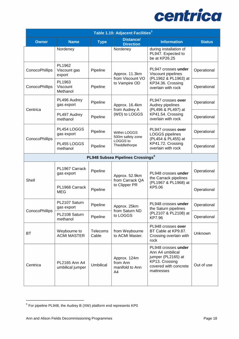
Table 1.10: Adjacent Facilities3
Owner Name Type Distance/ Direction
Information Status
Nordeney Nordeney during installation of PL947. Expected to be at KP26.25
ConocoPhillips PL1962 Viscount gas export
Pipeline Approx. 11.3km from Viscount VO to Vampire OD
PL947 crosses under Viscount pipelines (PL1962 & PL1963) at KP34.36. Crossing overlain with rock
Operational
ConocoPhillips PL1963 Viscount Methanol
Pipeline Operational
Centrica
PL496 Audrey gas export
Pipeline Approx. 16.4km from Audrey A (WD) to LOGGS
PL947 crosses over Audrey pipelines (PL496 & PL497) at KP41.54. Crossing overlain with rock
Operational
PL497 Audrey methanol
Pipeline Operational
ConocoPhillips
PL454 LOGGS gas export
Pipeline Within LOGGS 500m safety zone LOGGS to Theddlethorpe
PL947 crosses over LOGGS pipelines (PL454 & PL455) at KP41.72. Crossing overlain with rock
Operational
PL455 LOGGS methanol
Pipeline Operational
PL948 Subsea Pipelines Crossings5
Shell
PL1967 Carrack gas export
Pipeline Approx. 52.9km from Carrack QA to Clipper PR
PL948 crosses under the Carrack pipelines (PL1967 & PL1968) at KP5.06
Operational
PL1968 Carrack MEG
Pipeline Operational
ConocoPhillips
PL2107 Saturn gas export
Pipeline Approx. 25km from Saturn ND to LOGGS
PL948 crosses under the Saturn pipelines (PL2107 & PL2108) at KP7.96
Operational
PL2108 Saturn methanol
Pipeline Operational
BT Weybourne to ACMI MASTER
Telecoms Cable
from Weybourne to ACMI Master.
PL948 crosses over BT Cable at KP9.87. Crossing overlain with rock
Unknown
Centrica PL2165 Ann A4 umbilical jumper
Umbilical
Approx. 124m from Ann manifold to Ann A4
PL948 crosses under Ann A4 umbilical jumper (PL2165) at KP13. Crossing covered with concrete mattresses
Out of use
5 For pipeline PL948, the Audrey B (XW) platform end represents KP0
Ann and Alison Fields Decommissioning Programmes Page 19
Table 1.10: Adjacent Facilities3
Owner Name Type Distance/ Direction
Information Status
PL1099 Subsea Pipelines Crossings6
ConocoPhillips
PL2107 Saturn gas export
Pipeline Approx. 35.7km from Saturn ND
to LOGGS
PL1099 crosses under the Saturn
pipelines (PL2107 & PL2108) at KP8.38
Operational
PL2108 Saturn methanol
Pipeline Operational
Unknown Weybourne to
Fano Cable
Weybourne to Fano
PL1099 trenched and buried at KP10.05
Out of use
Centrica PL947 Ann gas
export Pipeline
Approx. 41.8km from Ann to
LOGGS
PL1099 crosses over Ann pipeline (PL947) at KP14.93. Crossing covered with concrete
mattresses
Out of use
Impacts of Decommissioning Proposals
There are no direct impacts on adjacent facilities from the associated decommissioning works outside the LOGGS complex. Timing of works within the LOGGS 500m zone will be agreed with the LOGGS owner.
Where crossings are overlain with rock, it is proposed to decommission the rock and the infrastructure beneath by leaving in situ.
As part of the environmental assessment we have considered potential in combination or cumulative effect of activities in the area, including decommissioning and aggregate extraction. This was completed using data that are publicly available. However, operational windows tend to include a degree of flexibility so it is not possible to be precise. However, as part of the operational phase any potential impacts will be mitigated in two ways. The first is via direct communication with the parties involved, and the other is via submission of the MATs and SATs.
6 For pipeline PL1099, the Audrey B (XW) platform end represents KP0
Ann and Alison Fields Decommissioning Programmes Page 20
Figure 1.7: Adjacent Facilities

Ann and Alison Fields Decommissioning Programmes Page 21
1.8 Industrial Implications
Well abandonment and removal will be completed using a drilling rig. Some preparatory work will be undertaken by a light well intervention vessel and/or a diving support vessel subject to commercial considerations.
It is Centrica’s intention to use a combination of existing framework agreements and new contracts for the decommissioning of Ann and Alison installations. Subject to collaborative effort and commercial agreements, Centrica are also planning to combine Ann and Alison decommissioning activities with other development or decommissioning activities such as the abandonment of the ConocoPhillips’ owned “KX” well at Alison. A drilling rig will be sourced in 2017 for a number of well abandonment activities in the Southern North Sea and as such it is possible that the sequence of work may change.
Ann and Alison Fields Decommissioning Programmes Page 22
2 DESCRIPTION OF ITEMS TO BE DECOMMISSIONED
2.1 Ann Field
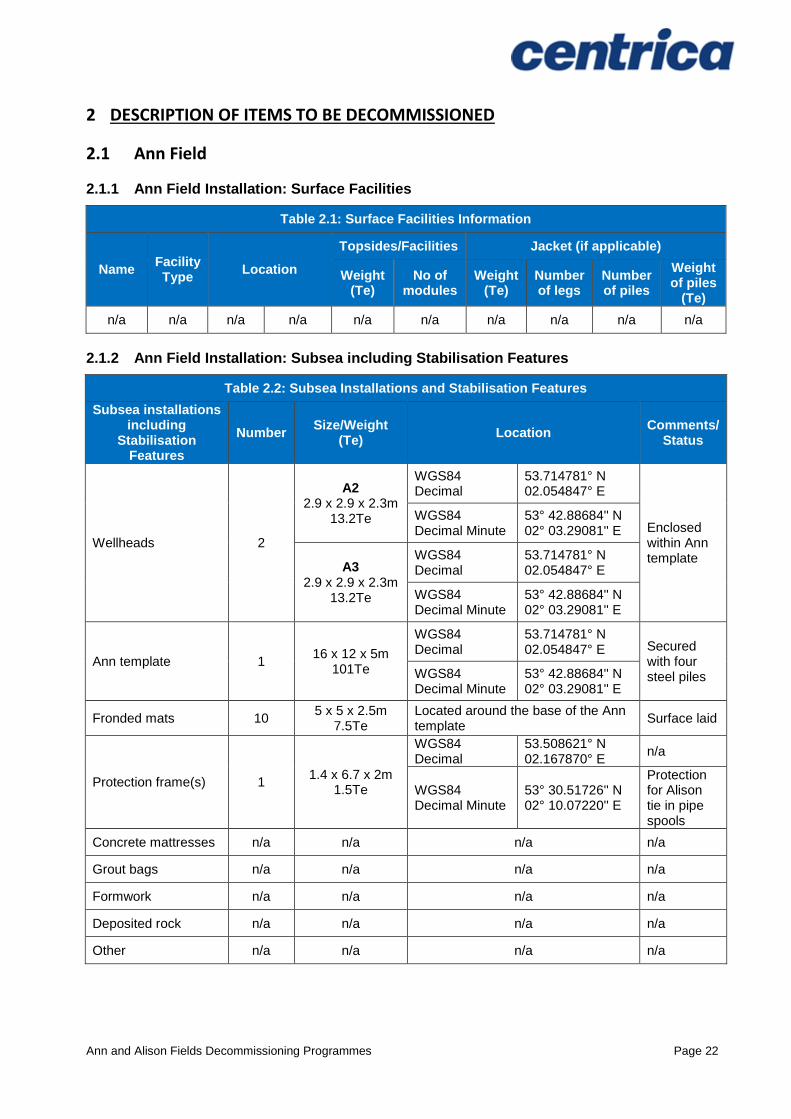
2.1.1 Ann Field Installation: Surface Facilities
Table 2.1: Surface Facilities Information
Name Facility Type
Location
Topsides/Facilities Jacket (if applicable)
Weight (Te)
No of modules
Weight (Te)
Number of legs
Number of piles
Weight of piles
(Te)
n/a n/a n/a n/a n/a n/a n/a n/a n/a n/a
2.1.2 Ann Field Installation: Subsea including Stabilisation Features
Table 2.2: Subsea Installations and Stabilisation Features
Subsea installations including
Stabilisation Features
Number Size/Weight
(Te) Location
Comments/ Status
Wellheads 2
A2 2.9 x 2.9 x 2.3m
13.2Te
WGS84 Decimal
53.714781° N 02.054847° E
Enclosed within Ann template
WGS84 Decimal Minute
53° 42.88684'' N 02° 03.29081'' E
A3 2.9 x 2.9 x 2.3m
13.2Te
WGS84 Decimal
53.714781° N 02.054847° E
WGS84 Decimal Minute
53° 42.88684'' N 02° 03.29081'' E
Ann template 1 16 x 12 x 5m
101Te
WGS84 Decimal
53.714781° N 02.054847° E Secured
with four steel piles WGS84
Decimal Minute 53° 42.88684'' N 02° 03.29081'' E
Fronded mats 10 5 x 5 x 2.5m
7.5Te Located around the base of the Ann template
Surface laid
Protection frame(s) 1 1.4 x 6.7 x 2m
1.5Te
WGS84 Decimal
53.508621° N 02.167870° E
n/a
WGS84 Decimal Minute
53° 30.51726'' N 02° 10.07220'' E
Protection for Alison tie in pipe spools
Concrete mattresses n/a n/a n/a n/a
Grout bags n/a n/a n/a n/a
Formwork n/a n/a n/a n/a
Deposited rock n/a n/a n/a n/a
Other n/a n/a n/a n/a
Ann and Alison Fields Decommissioning Programmes Page 23
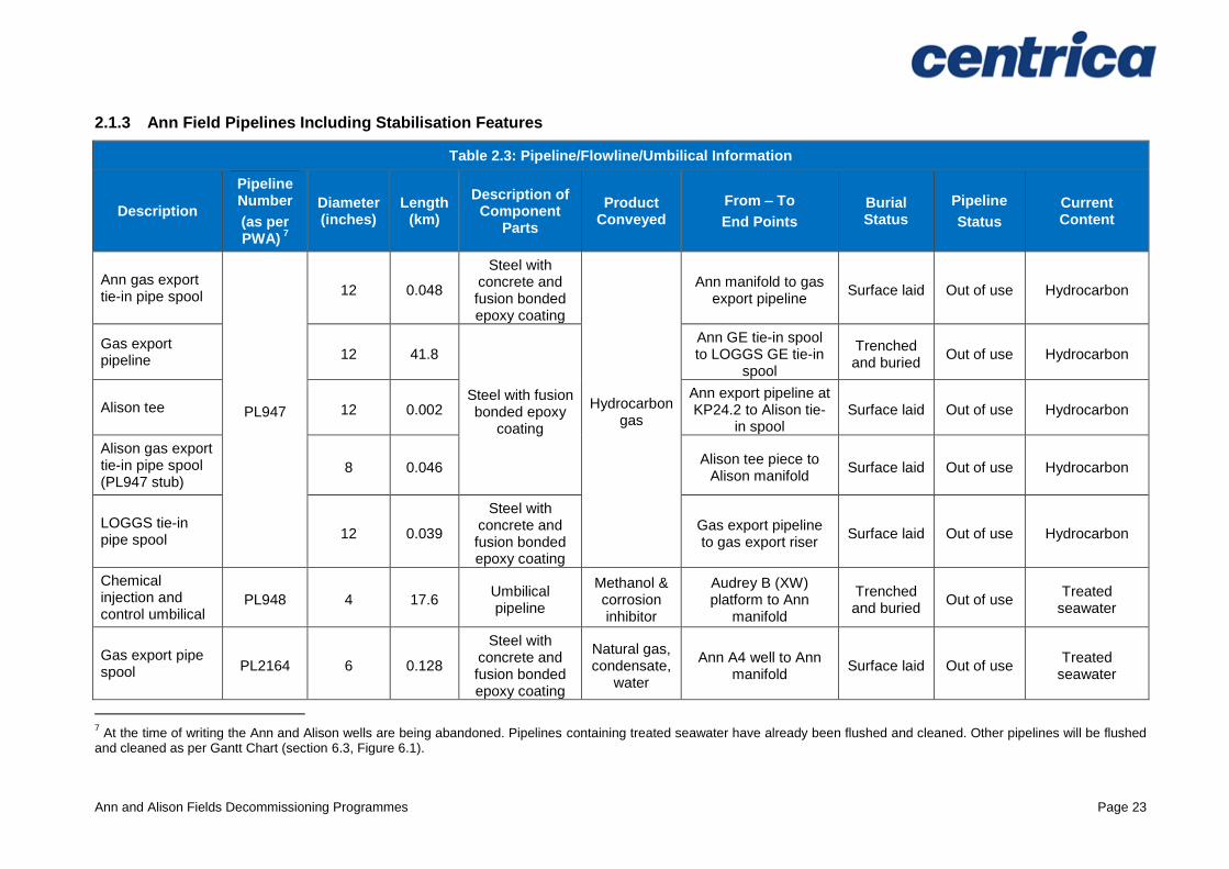
2.1.3 Ann Field Pipelines Including Stabilisation Features
Table 2.3: Pipeline/Flowline/Umbilical Information
Description
Pipeline Number
(as per PWA)
7
Diameter (inches)
Length (km)
Description of Component
Parts
Product Conveyed
From – To
End Points
Burial Status
Pipeline
Status
Current Content
Ann gas export tie-in pipe spool
PL947
12 0.048
Steel with concrete and fusion bonded epoxy coating
Hydrocarbon gas
Ann manifold to gas export pipeline
Surface laid Out of use Hydrocarbon
Gas export pipeline 12 41.8
Steel with fusion bonded epoxy
coating
Ann GE tie-in spool to LOGGS GE tie-in
spool
Trenched and buried
Out of use Hydrocarbon
Alison tee 12 0.002 Ann export pipeline at KP24.2 to Alison tie-
in spool Surface laid Out of use Hydrocarbon
Alison gas export tie-in pipe spool (PL947 stub)
8 0.046 Alison tee piece to
Alison manifold Surface laid Out of use Hydrocarbon
LOGGS tie-in pipe spool 12 0.039
Steel with concrete and fusion bonded epoxy coating
Gas export pipeline to gas export riser
Surface laid Out of use Hydrocarbon
Chemical injection and control umbilical
PL948 4 17.6 Umbilical pipeline
Methanol & corrosion inhibitor
Audrey B (XW) platform to Ann
manifold
Trenched and buried
Out of use Treated
seawater
Gas export pipe spool PL2164 6 0.128
Steel with concrete and fusion bonded epoxy coating
Natural gas, condensate,
water
Ann A4 well to Ann manifold
Surface laid Out of use Treated
seawater
7 At the time of writing the Ann and Alison wells are being abandoned. Pipelines containing treated seawater have already been flushed and cleaned. Other pipelines will be flushed
and cleaned as per Gantt Chart (section 6.3, Figure 6.1).
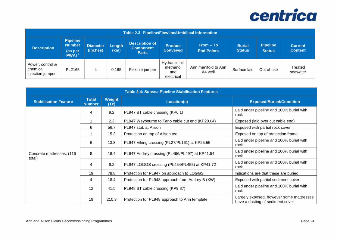
Ann and Alison Fields Decommissioning Programmes Page 24
Table 2.3: Pipeline/Flowline/Umbilical Information
Description
Pipeline Number
(as per PWA)
7
Diameter (inches)
Length (km)
Description of Component
Parts
Product Conveyed
From – To
End Points
Burial Status
Pipeline
Status
Current Content
Power, control & chemical injection jumper
PL2165 4 0.165 Flexible jumper
Hydraulic oil, methanol
and electrical
Ann manifold to Ann A4 well
Surface laid Out of use Treated
seawater
Table 2.4: Subsea Pipeline Stabilisation Features
Stabilisation Feature Total
Number Weight
(Te) Location(s) Exposed/Buried/Condition
Concrete mattresses, (116 total)
4 9.2 PL947 BT cable crossing (KP6.1) Laid under pipeline and 100% burial with rock
1 2.3 PL947 Weybourne to Fano cable cut end (KP20.04) Exposed (laid over cut cable end)
6 56.7 PL947 stub at Alison Exposed with partial rock cover
1 15.3 Protection on top of Alison tee Exposed on top of protection frame
6 13.8 PL947 Viking crossing (PL27/PL161) at KP25.55 Laid under pipeline and 100% burial with rock
8 18.4 PL947 Audrey crossing (PL496/PL497) at KP41.54 Laid under pipeline and 100% burial with rock
4 9.2 PL947 LOGGS crossing (PL454/PL455) at KP41.72 Laid under pipeline and 100% burial with rock
19 78.8 Protection for PL947 on approach to LOGGS Indications are that these are buried
4 18.4 Protection for PL948 approach from Audrey B (XW) Exposed with partial sediment cover
12 41.5 PL948 BT cable crossing (KP9.87) Laid under pipeline and 100% burial with rock
19 210.3 Protection for PL948 approach to Ann template Largely exposed, however some mattresses have a dusting of sediment cover
Ann and Alison Fields Decommissioning Programmes Page 25
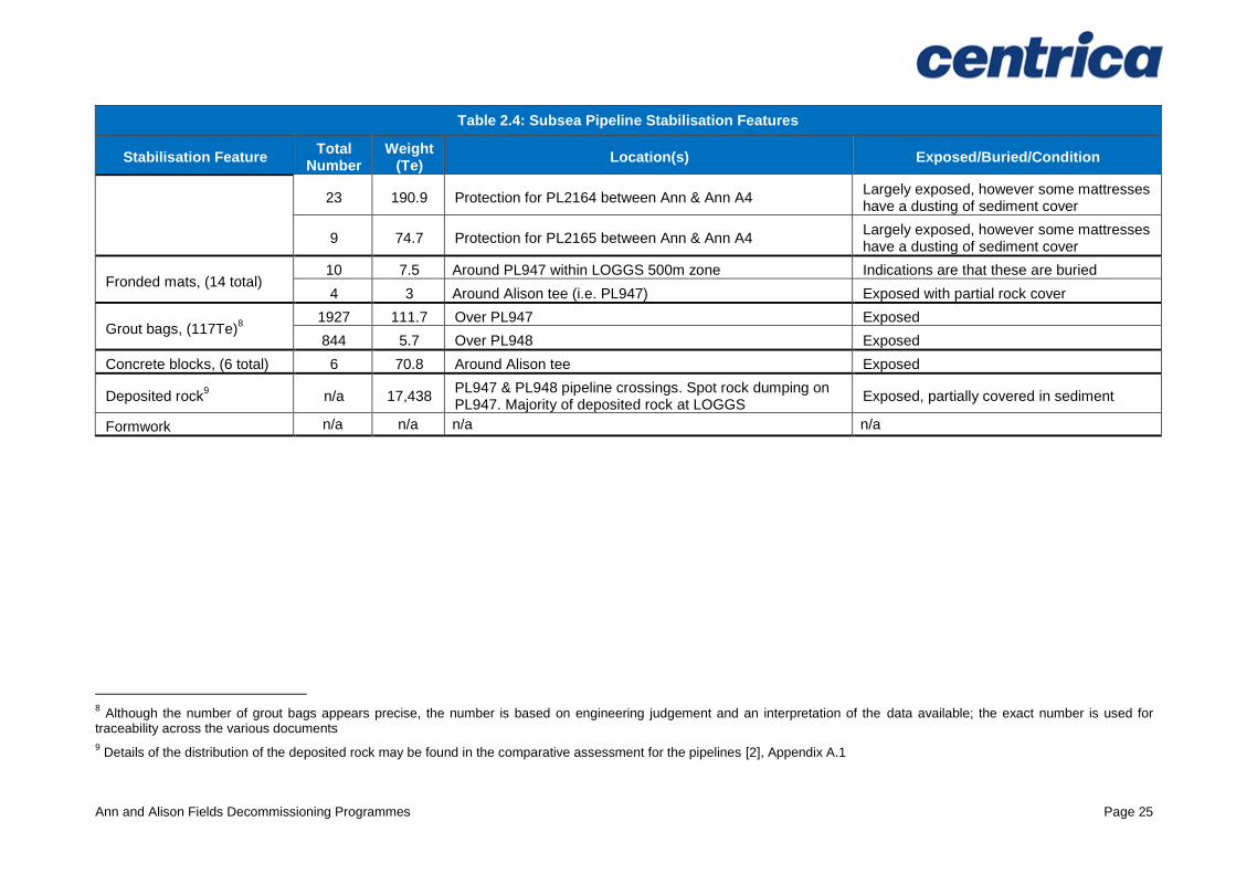
Table 2.4: Subsea Pipeline Stabilisation Features
Stabilisation Feature Total
Number Weight
(Te) Location(s) Exposed/Buried/Condition
23 190.9 Protection for PL2164 between Ann & Ann A4 Largely exposed, however some mattresses have a dusting of sediment cover
9 74.7 Protection for PL2165 between Ann & Ann A4 Largely exposed, however some mattresses have a dusting of sediment cover
Fronded mats, (14 total) 10 7.5 Around PL947 within LOGGS 500m zone Indications are that these are buried
4 3 Around Alison tee (i.e. PL947) Exposed with partial rock cover
Grout bags, (117Te)8
1927 111.7 Over PL947 Exposed
844 5.7 Over PL948 Exposed
Concrete blocks, (6 total) 6 70.8 Around Alison tee Exposed
Deposited rock9 n/a 17,438
PL947 & PL948 pipeline crossings. Spot rock dumping on PL947. Majority of deposited rock at LOGGS
Exposed, partially covered in sediment
Formwork n/a n/a n/a n/a
8 Although the number of grout bags appears precise, the number is based on engineering judgement and an interpretation of the data available; the exact number is used for
traceability across the various documents
9 Details of the distribution of the deposited rock may be found in the comparative assessment for the pipelines [2], Appendix A.1
Ann and Alison Fields Decommissioning Programmes Page 26
2.1.4 Ann Wells
Table 2.5: Well Information
Platform Wells Designation Status Category of Well
n/a n/a n/a n/a
Subsea Wells Designation Status Category of Well
46/6a-A2 Gas production Shut in SS-1-3-3
49/6a-A3z Gas production Shut in SS-1-3-3
For details of well categorisation see Oil & Gas UK Guidelines for the Abandonment of Wells. Issue 5, July 2015.
Note: There are three subsea wells in the Ann field, however only two form part of this Decommissioning Programme. The third well (Ann A4) has been submitted as part of a separate Decommissioning Programme [1].
2.1.5 Ann Drill Cuttings
Table 2.6: Drill Cuttings Pile(s) Information
Location of Pile Centre (Latitude/Longitude)
Seabed Area (m
2)
Estimated volume of cuttings (m
3)
No drill cuttings pile exists at Ann. Please refer Section 2 of the Ann Pre-decommissioning Environmental Survey [5].
n/a n/a
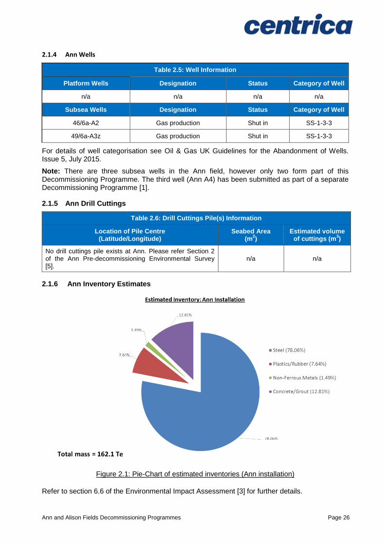
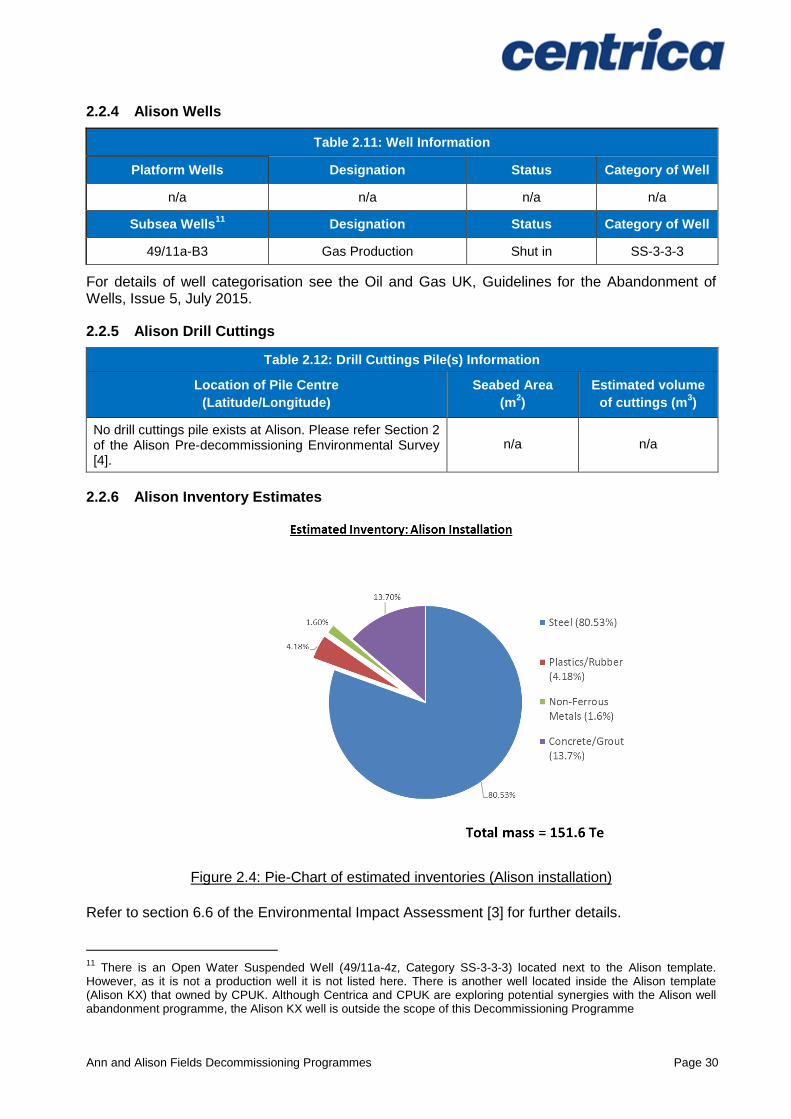
2.1.6 Ann Inventory Estimates
Figure 2.1: Pie-Chart of estimated inventories (Ann installation)
Refer to section 6.6 of the Environmental Impact Assessment [3] for further details.
Ann and Alison Fields Decommissioning Programmes Page 27
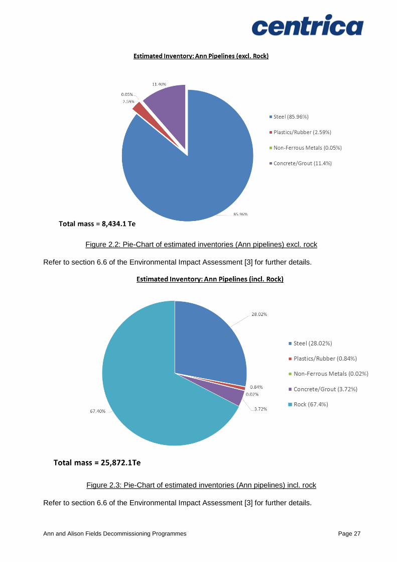
Figure 2.2: Pie-Chart of estimated inventories (Ann pipelines) excl. rock
Refer to section 6.6 of the Environmental Impact Assessment [3] for further details.
Figure 2.3: Pie-Chart of estimated inventories (Ann pipelines) incl. rock
Refer to section 6.6 of the Environmental Impact Assessment [3] for further details.
Ann and Alison Fields Decommissioning Programmes Page 28
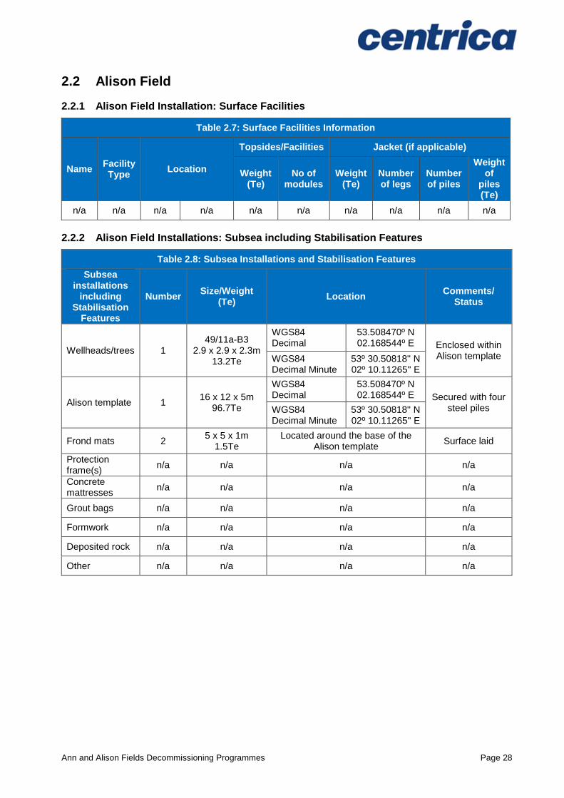
2.2 Alison Field
2.2.1 Alison Field Installation: Surface Facilities
Table 2.7: Surface Facilities Information
Name Facility Type
Location
Topsides/Facilities Jacket (if applicable)
Weight (Te)
No of modules
Weight (Te)
Number of legs
Number of piles
Weight of
piles (Te)
n/a n/a n/a n/a n/a n/a n/a n/a n/a n/a
2.2.2 Alison Field Installations: Subsea including Stabilisation Features
Table 2.8: Subsea Installations and Stabilisation Features
Subsea installations
including Stabilisation
Features
Number Size/Weight
(Te) Location
Comments/ Status
Wellheads/trees 1 49/11a-B3
2.9 x 2.9 x 2.3m 13.2Te
WGS84 Decimal
53.508470º N 02.168544º E Enclosed within
Alison template WGS84 Decimal Minute
53º 30.50818'' N 02º 10.11265'' E
Alison template 1 16 x 12 x 5m
96.7Te
WGS84 Decimal
53.508470º N 02.168544º E Secured with four
steel piles WGS84 Decimal Minute
53º 30.50818'' N 02º 10.11265'' E
Frond mats 2 5 x 5 x 1m
1.5Te Located around the base of the
Alison template Surface laid
Protection frame(s)
n/a n/a n/a n/a
Concrete mattresses
n/a n/a n/a n/a
Grout bags n/a n/a n/a n/a
Formwork n/a n/a n/a n/a
Deposited rock n/a n/a n/a n/a
Other n/a n/a n/a n/a
Ann and Alison Fields Decommissioning Programmes Page 29
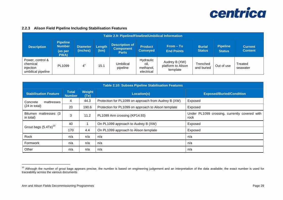
2.2.3 Alison Field Pipeline Including Stabilisation Features
Table 2.9: Pipeline/Flowline/Umbilical Information
Description Pipeline Number
(as per PWA)
Diameter (inches)
Length (km)
Description of Component
Parts
Product Conveyed
From – To
End Points
Burial Status
Pipeline
Status
Current Content
Power, control & chemical injection umbilical pipeline
PL1099 4” 15.1 Umbilical pipeline
Hydraulic oil,
methanol, electrical
Audrey B (XW) platform to Alison
template
Trenched and buried
Out of use Treated seawater
Table 2.10: Subsea Pipeline Stabilisation Features
Stabilisation Feature Total
Number Weight
(Te) Location(s) Exposed/Buried/Condition
Concrete mattresses (24 in total)
4 44.3 Protection for PL1099 on approach from Audrey B (XW) Exposed
20 190.6 Protection for PL1099 on approach to Alison template Exposed
Bitumen mattresses (3 in total)
3 11.2 PL1099 Ann crossing (KP14.93) Under PL1099 crossing, currently covered with rock
Grout bags (5.4Te)10
40 1 On PL1099 approach to Audrey B (XW) Exposed
170 4.4 On PL1099 approach to Alison template Exposed
Rock n/a n/a n/a n/a
Formwork n/a n/a n/a n/a
Other n/a n/a n/a n/a
10
Although the number of grout bags appears precise, the number is based on engineering judgement and an interpretation of the data available; the exact number is used for traceability across the various documents
Ann and Alison Fields Decommissioning Programmes Page 30
2.2.4 Alison Wells
Table 2.11: Well Information
Platform Wells Designation Status Category of Well
n/a n/a n/a n/a
Subsea Wells11
Designation Status Category of Well
49/11a-B3 Gas Production Shut in SS-3-3-3
For details of well categorisation see the Oil and Gas UK, Guidelines for the Abandonment of Wells, Issue 5, July 2015.
2.2.5 Alison Drill Cuttings
Table 2.12: Drill Cuttings Pile(s) Information
Location of Pile Centre
(Latitude/Longitude)
Seabed Area
(m2)
Estimated volume
of cuttings (m3)
No drill cuttings pile exists at Alison. Please refer Section 2 of the Alison Pre-decommissioning Environmental Survey [4].
n/a n/a
2.2.6 Alison Inventory Estimates
Figure 2.4: Pie-Chart of estimated inventories (Alison installation)
Refer to section 6.6 of the Environmental Impact Assessment [3] for further details.
11
There is an Open Water Suspended Well (49/11a-4z, Category SS-3-3-3) located next to the Alison template. However, as it is not a production well it is not listed here. There is another well located inside the Alison template (Alison KX) that owned by CPUK. Although Centrica and CPUK are exploring potential synergies with the Alison well abandonment programme, the Alison KX well is outside the scope of this Decommissioning Programme
Ann and Alison Fields Decommissioning Programmes Page 31
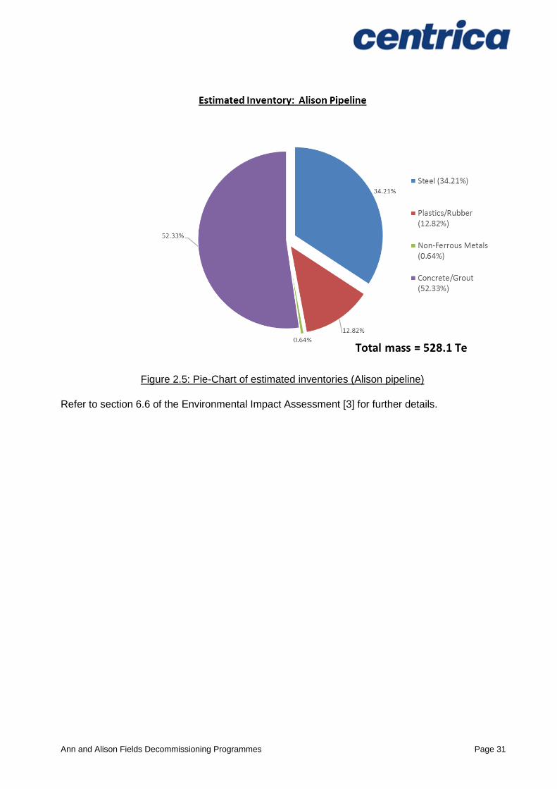
Figure 2.5: Pie-Chart of estimated inventories (Alison pipeline)
Refer to section 6.6 of the Environmental Impact Assessment [3] for further details.
Ann and Alison Fields Decommissioning Programmes Page 32
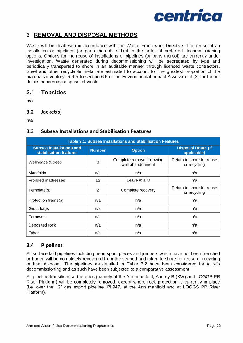
3 REMOVAL AND DISPOSAL METHODS
Waste will be dealt with in accordance with the Waste Framework Directive. The reuse of an installation or pipelines (or parts thereof) is first in the order of preferred decommissioning options. Options for the reuse of installations or pipelines (or parts thereof) are currently under investigation. Waste generated during decommissioning will be segregated by type and periodically transported to shore in an auditable manner through licensed waste contractors. Steel and other recyclable metal are estimated to account for the greatest proportion of the materials inventory. Refer to section 6.6 of the Environmental Impact Assessment [3] for further details concerning disposal of waste.
3.1 Topsides
n/a
3.2 Jacket(s)
n/a
3.3 Subsea Installations and Stabilisation Features
Table 3.1: Subsea Installations and Stabilisation Features
Subsea installations and stabilisation features
Number Option Disposal Route (if
applicable)
Wellheads & trees 3 Complete removal following
well abandonment Return to shore for reuse
or recycling
Manifolds n/a n/a n/a
Fronded mattresses 12 Leave in situ n/a
Template(s) 2 Complete recovery Return to shore for reuse
or recycling
Protection frame(s) n/a n/a n/a
Grout bags n/a n/a n/a
Formwork n/a n/a n/a
Deposited rock n/a n/a n/a
Other n/a n/a n/a
3.4 Pipelines
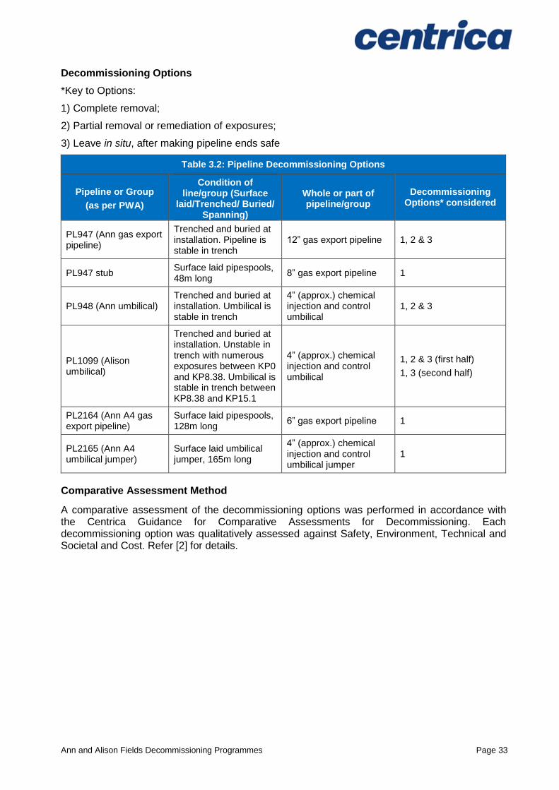
All surface laid pipelines including tie-in spool pieces and jumpers which have not been trenched or buried will be completely recovered from the seabed and taken to shore for reuse or recycling or final disposal. The pipelines as detailed in Table 3.2 have been considered for in situ decommissioning and as such have been subjected to a comparative assessment.
All pipeline transitions at the ends (namely at the Ann manifold, Audrey B (XW) and LOGGS PR Riser Platform) will be completely removed, except where rock protection is currently in place (i.e. over the 12” gas export pipeline, PL947, at the Ann manifold and at LOGGS PR Riser Platform).
Ann and Alison Fields Decommissioning Programmes Page 33
Decommissioning Options
*Key to Options:
1) Complete removal;
2) Partial removal or remediation of exposures;
3) Leave in situ, after making pipeline ends safe
Table 3.2: Pipeline Decommissioning Options
Pipeline or Group
(as per PWA)
Condition of line/group (Surface
laid/Trenched/ Buried/ Spanning)
Whole or part of pipeline/group
Decommissioning Options* considered
PL947 (Ann gas export pipeline)
Trenched and buried at installation. Pipeline is stable in trench
12” gas export pipeline 1, 2 & 3
PL947 stub Surface laid pipespools, 48m long
8” gas export pipeline 1
PL948 (Ann umbilical) Trenched and buried at installation. Umbilical is stable in trench
4” (approx.) chemical injection and control umbilical
1, 2 & 3
PL1099 (Alison umbilical)
Trenched and buried at installation. Unstable in trench with numerous exposures between KP0 and KP8.38. Umbilical is stable in trench between KP8.38 and KP15.1
4” (approx.) chemical injection and control umbilical
1, 2 & 3 (first half)
1, 3 (second half)
PL2164 (Ann A4 gas export pipeline)
Surface laid pipespools, 128m long
6” gas export pipeline 1
PL2165 (Ann A4 umbilical jumper)
Surface laid umbilical jumper, 165m long
4” (approx.) chemical injection and control umbilical jumper
1
Comparative Assessment Method
A comparative assessment of the decommissioning options was performed in accordance with the Centrica Guidance for Comparative Assessments for Decommissioning. Each decommissioning option was qualitatively assessed against Safety, Environment, Technical and Societal and Cost. Refer [2] for details.
Ann and Alison Fields Decommissioning Programmes Page 34
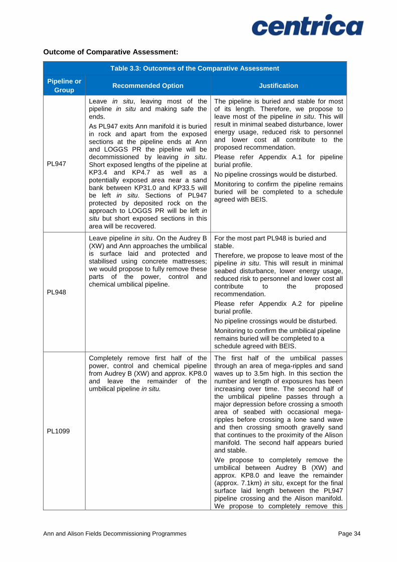
Outcome of Comparative Assessment:
Table 3.3: Outcomes of the Comparative Assessment
Pipeline or
Group Recommended Option Justification
PL947
Leave in situ, leaving most of the pipeline in situ and making safe the ends.
As PL947 exits Ann manifold it is buried in rock and apart from the exposed sections at the pipeline ends at Ann and LOGGS PR the pipeline will be decommissioned by leaving in situ. Short exposed lengths of the pipeline at KP3.4 and KP4.7 as well as a potentially exposed area near a sand bank between KP31.0 and KP33.5 will be left in situ. Sections of PL947 protected by deposited rock on the approach to LOGGS PR will be left in situ but short exposed sections in this area will be recovered.
The pipeline is buried and stable for most of its length. Therefore, we propose to leave most of the pipeline in situ. This will result in minimal seabed disturbance, lower energy usage, reduced risk to personnel and lower cost all contribute to the proposed recommendation.
Please refer Appendix A.1 for pipeline burial profile.
No pipeline crossings would be disturbed.
Monitoring to confirm the pipeline remains buried will be completed to a schedule agreed with BEIS.
PL948
Leave pipeline in situ. On the Audrey B (XW) and Ann approaches the umbilical is surface laid and protected and stabilised using concrete mattresses; we would propose to fully remove these parts of the power, control and chemical umbilical pipeline.
For the most part PL948 is buried and stable.
Therefore, we propose to leave most of the pipeline in situ. This will result in minimal seabed disturbance, lower energy usage, reduced risk to personnel and lower cost all contribute to the proposed recommendation.
Please refer Appendix A.2 for pipeline burial profile.
No pipeline crossings would be disturbed.
Monitoring to confirm the umbilical pipeline remains buried will be completed to a schedule agreed with BEIS.
PL1099
Completely remove first half of the power, control and chemical pipeline from Audrey B (XW) and approx. KP8.0 and leave the remainder of the umbilical pipeline in situ.
The first half of the umbilical passes through an area of mega-ripples and sand waves up to 3.5m high. In this section the number and length of exposures has been increasing over time. The second half of the umbilical pipeline passes through a major depression before crossing a smooth area of seabed with occasional mega-ripples before crossing a lone sand wave and then crossing smooth gravelly sand that continues to the proximity of the Alison manifold. The second half appears buried and stable.
We propose to completely remove the umbilical between Audrey B (XW) and approx. KP8.0 and leave the remainder (approx. 7.1km) in situ, except for the final surface laid length between the PL947 pipeline crossing and the Alison manifold. We propose to completely remove this
Ann and Alison Fields Decommissioning Programmes Page 35
Table 3.3: Outcomes of the Comparative Assessment
Pipeline or
Group Recommended Option Justification
section.
Please refer Appendix A.3 for pipeline burial profile.
Monitoring to confirm the remaining umbilical pipeline remains buried will be completed to a schedule agreed with BEIS.
PL947 stub
Completely remove all pipespools and pipeline stabilisation features.
This pipeline and associated stabilisation features are surface laid. We believe that to leave these elements in situ would render the pipeline and stabilisation features vulnerable to damage during fishing activities from beam trawls, requiring future remedial activities
PL2164 Completely remove all pipespools and pipeline stabilisation features
As per PL947 stub described above
PL2165
Completely remove the umbilical jumper and all associated pipeline stabilisation features, most of which are shared with PL2164
As per PL947 stub described above
Ann and Alison Fields Decommissioning Programmes Page 36
3.5 Pipeline Stabilisation Features
Table 3.4: Pipeline Stabilisation Features
Stabilisation Features
Number Option Disposal Route (if
applicable)
Concrete mattresses
Approaches:
102
Complete recovery of those elements that are not buried
Recovered to shore for recycling or disposal to landfill
Crossings:
38
Leave in situ as part of pipeline crossing as buried under existing rock
Leave in situ
Bitumen mattresses Crossings:
3 Complete recovery
Recovered to shore for recycling or disposal to landfill.
Frond mattresses Installations:
14
Leave in situ (buried under sediment)
Leave in situ
Grout bags
Crossings:
162 x 25kg
Leave in situ as part of pipeline crossing as buried under existing rock
Leave in situ
Approaches:
2576 x 25kg
53 x 1000kg
Complete recovery Recovered to shore for recycling or disposal to landfill.
Concrete blocks 6 Complete recovery Recovered to shore for recycling or disposal to landfill
Rock dump (existing) 17,438Te Leave in situ Leave in situ
Ann and Alison Fields Decommissioning Programmes Page 37
Figure 3.1: Overview of pipeline decommissioning proposals
Ann and Alison Fields Decommissioning Programmes Page 38
3.6 Wells
Table 3.5: Well Plug and Abandonment
The Ann and Alison fields contain a total of four Centrica owned subsea production wells and one open water suspended well.
Within the Ann field, two production wells (Ann A2 and A3) are located within the Ann template as listed in Section 2.1.4 (Table 2.5), and a third well (Ann A4) has been described in a separate Decommissioning Programme [1].
Within the Alison field, there is one Centrica owned production well located within the Alison manifold (49/11a-B3) as listed in 2.2.4 (Table 2.11) and one open water suspended well located adjacent to the Alison manifold.
There is also a second well (KX) within the Alison manifold, which is owned by CPUK and does not form part of this Decommissioning Programme.
The wells will be plugged and abandoned in accordance with Oil & Gas UK Guidelines for the Abandonment of Wells, Issue 5, July 2015. A Master Application Template (MAT) and the supporting Subsidiary Application Template(s) (SAT) will be submitted in support of works carried out. A PON5 and the appropriate marine licenses will also be submitted to BEIS for application to abandon the wells. Well abandonment activities are scheduled to occur in 2017.
Ann and Alison Fields Decommissioning Programmes Page 39
3.7 Drill Cuttings
There is no existing drill cuttings pile associated with either the Ann or Alison installations. This conclusion is supported by the bathymetry from the 2016 surveys [4] and [5] which showed no evidence of an accumulation of cuttings at the locations. Recent survey data suggests that the level of barium (an indicator of the presence of contamination from drilling) is slightly elevated compared to reference levels at only one station. While this might indicate the presence of residual drilling discharges, it does not indicate the presence of drill cuttings.
3.8 Waste Streams
Table 3.6: Waste Stream Management Methods
Waste Stream Removal and Disposal method
Bulk Liquids
The pipeline will be pigged, flushed and left filled with seawater. The corrosion inhibitor and methanol will be removed from the umbilical pipeline prior to the start of the decommissioning activities. Bulk fluids will be disposed down a donor well on North Valiant platform that is located adjacent to the LOGGS complex. Any residual fluids from within the sections of pipeline and umbilical pipelines will be released to marine environment under permit prior to removal to shore. Further cleaning and decontamination will take place onshore prior to recycling or re-use.
Marine Growth Where necessary and practicable to allow access, some marine growth will be removed offshore. The remainder will be brought to shore and disposed of in accordance with guidelines and company policies.
NORM/LSA Scale
Tests for NORM will be performed offshore and any NORM encountered will be dealt with and disposed of under the appropriate permit and managed in accordance with guidelines and company policies.
Asbestos No asbestos is associated with the Ann and Alison installations or pipelines.
Other hazardous wastes
Other hazardous wastes will be recovered to shore and disposed of under the appropriate permit and managed in accordance with guidelines and company policies.
Onshore Dismantling sites
Appropriate licenced sites will be selected. Facility chosen must demonstrate proven disposal track record and waste stream management throughout the deconstruction process.
Table 3.7: Inventory Disposition
Inventory Total inventory
tonnage Planned tonnage to
shore Planned left in situ
Ann Installation 162 136 26
Ann Pipelines 8,434 1,045 7,389
Ann Pipelines (rock) 17,438 0 17,438
Alison Installation 152 126 26
Alison Pipeline 528 403 125
In Table 3.7 a distinction is made between the planned quantity of material decommissioned in situ and materials that would be recovered to shore.
All recovered material will be transported onshore for reuse, recycling or disposal. It is not possible to predict the market for reusable materials with any confidence; the figures in Table 3.8 are aspirational percentages for disposal.

Ann and Alison Fields Decommissioning Programmes Page 40
Table 3.8: Re-use, Recycle & Disposal Aspirations for Material Recovered to Shore
Inventory Re-use Recycle Disposal
Ann Installation (136Te) <5% >95% <5%
Ann Pipelines (1,045Te) <5% >95% <5%
Alison Installation (126Te) <5% >95% <5%
Alison Pipeline (403Te) <5% >95% <5%
Please refer to Section 6.6 of the Environmental Impact Assessment [1] in Section 7 for further
details.
Ann and Alison Fields Decommissioning Programmes Page 41
4 ENVIRONMENTAL IMPACT ASSESSMENT
4.1 Environmental Sensitivities
Table 4.1: Environmental Sensitivities
Environmental Receptor Main Features
Conservation interests
No Annex I habitats have been identified in any surveys undertaken within or adjacent to the Ann and Alison wells. LOGGS is on one of the sandbanks for which the North Norfolk Sandbanks was designated. As the area is within a Harbour Porpoise Possible SAC, there is potential for a number of Annex II species to be present within the vicinity. However, the nature of the activities being undertaken is anticipated to have low impact significance upon these species. The majority of the infrastructure is within the North Norfolk Sandbank SCI, however the activities are not anticipated to have any impacts upon the site due to the small scale of the activities. In the event of a large hydrocarbon release, a proportion of the hydrocarbon could be captured within the seabed sediment. However, the possibility of such an event and the low concentrations that would be recorded within the sediment (comparable to background concentrations) mean the significance of the impact is considered low.
Seabed
The seabed in the Ann area comprises fine to medium sand developed into megaripples with scattered shell fragments and occasional gravel including pebbles and cobbles.
The seabed in the Alison area comprises sand with varying amounts of shell fragments, gravel, (including pebbles) and cobbles.
The seabed in the LOGGS area comprises sand with shells and shell fragments with sand waves and ripples indicating a mobile sandy seabed.
In general, the marine habitats and their associated species depend on the available substrate and sediment composition. Multivariate comparison of the survey data concluded that the macrofaunal community in the Ann, Alison and LOGGS survey area were characterised mainly according to natural variation in sediment composition (rather than contaminants).
The removal of installations, pipe spools, pipeline ends and protection features from the seabed will impact the seabed. Sensitive marine habitats are likely to be damaged as a result of seabed disturbance and the temporary placement of materials on the seabed. In addition, there is potential for re-suspended sediment to settle on sensitive habitat and species smothering them. However, the extent of the disturbance is likely to be minimal in comparison to the area of available habitat. The habitat observed is not unique to the area and represents a small proportion to that available within the wider Southern North Sea. In the event of a large hydrocarbon release, it was found that a proportion of the hydrocarbon could be captured within the sediment. However, given the likelihood of such an event and the low concentrations that would be recorded within the sediment (comparable to background concentrations) the significance of the impact is considered low.
Atmosphere
In general, offshore meteorological conditions will lead to rapid dispersion and dilution of atmospheric emissions. Impacts arising because of emissions (largely comprising combustion gases) are therefore likely to be short-term and highly localised and are assessed as of low significance.
Ann and Alison Fields Decommissioning Programmes Page 42
Table 4.1: Environmental Sensitivities
Environmental Receptor Main Features
The emission of combustion gases will contribute to global effects (e.g. global warming). However, given the relatively small volume of gases to be emitted and the control and mitigation measures that will be implemented the significance of the impact is low.
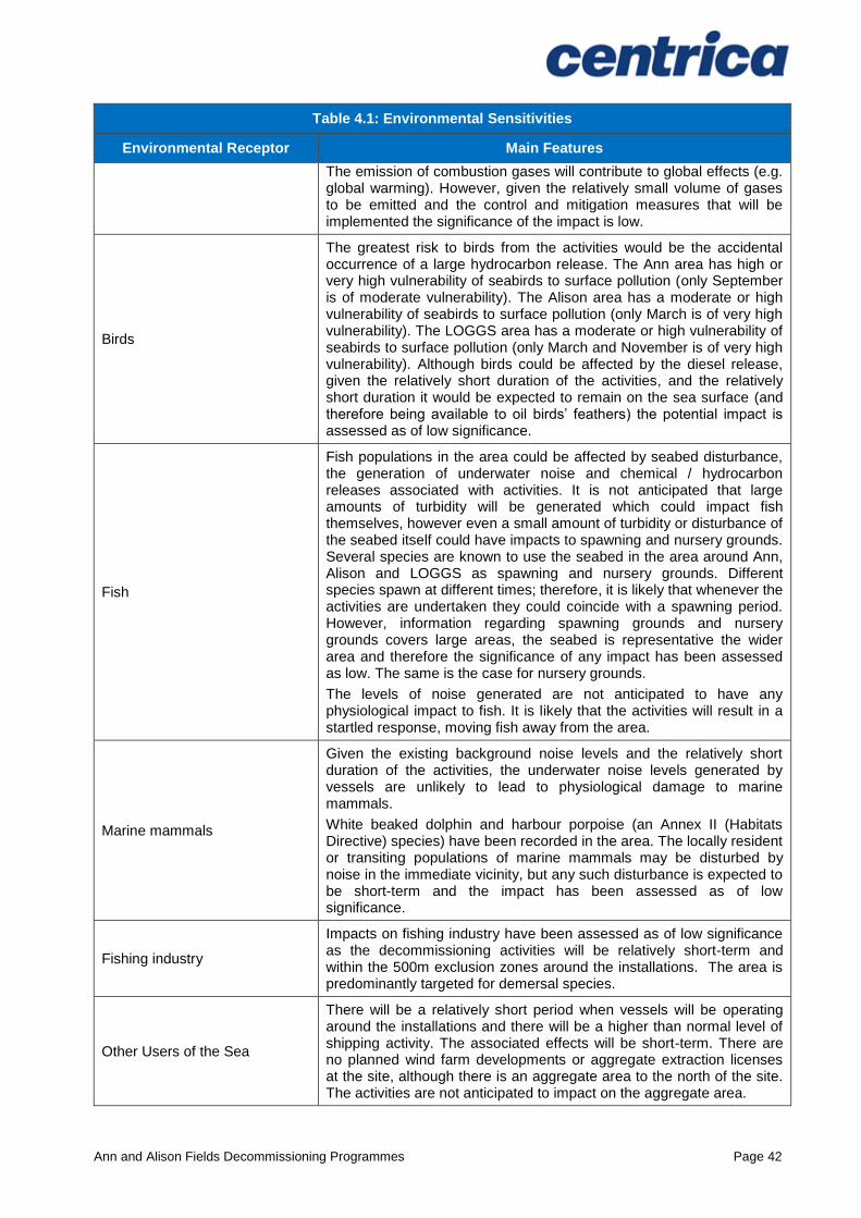
Birds
The greatest risk to birds from the activities would be the accidental occurrence of a large hydrocarbon release. The Ann area has high or very high vulnerability of seabirds to surface pollution (only September is of moderate vulnerability). The Alison area has a moderate or high vulnerability of seabirds to surface pollution (only March is of very high vulnerability). The LOGGS area has a moderate or high vulnerability of seabirds to surface pollution (only March and November is of very high vulnerability). Although birds could be affected by the diesel release, given the relatively short duration of the activities, and the relatively short duration it would be expected to remain on the sea surface (and therefore being available to oil birds’ feathers) the potential impact is assessed as of low significance.
Fish
Fish populations in the area could be affected by seabed disturbance, the generation of underwater noise and chemical / hydrocarbon releases associated with activities. It is not anticipated that large amounts of turbidity will be generated which could impact fish themselves, however even a small amount of turbidity or disturbance of the seabed itself could have impacts to spawning and nursery grounds. Several species are known to use the seabed in the area around Ann, Alison and LOGGS as spawning and nursery grounds. Different species spawn at different times; therefore, it is likely that whenever the activities are undertaken they could coincide with a spawning period. However, information regarding spawning grounds and nursery grounds covers large areas, the seabed is representative the wider area and therefore the significance of any impact has been assessed as low. The same is the case for nursery grounds.
The levels of noise generated are not anticipated to have any physiological impact to fish. It is likely that the activities will result in a startled response, moving fish away from the area.
Marine mammals
Given the existing background noise levels and the relatively short duration of the activities, the underwater noise levels generated by vessels are unlikely to lead to physiological damage to marine mammals.
White beaked dolphin and harbour porpoise (an Annex II (Habitats Directive) species) have been recorded in the area. The locally resident or transiting populations of marine mammals may be disturbed by noise in the immediate vicinity, but any such disturbance is expected to be short-term and the impact has been assessed as of low significance.
Fishing industry
Impacts on fishing industry have been assessed as of low significance as the decommissioning activities will be relatively short-term and within the 500m exclusion zones around the installations. The area is predominantly targeted for demersal species.
Other Users of the Sea
There will be a relatively short period when vessels will be operating around the installations and there will be a higher than normal level of shipping activity. The associated effects will be short-term. There are no planned wind farm developments or aggregate extraction licenses at the site, although there is an aggregate area to the north of the site. The activities are not anticipated to impact on the aggregate area.

Ann and Alison Fields Decommissioning Programmes Page 43
Table 4.1: Environmental Sensitivities
Environmental Receptor Main Features
Onshore Communities
The impact of the disposal of waste on onshore communities would be slightly beneficial as it will contribute to the continuation of jobs. However this is expected to be small as the disposal sites already exist and the volume of waste is relatively small.
Ann and Alison Fields Decommissioning Programmes Page 44
4.2 Potential Environmental Impacts and their Management
Environmental Impact Assessment Summary
There will be some planned and unplanned environmental impacts arising from decommissioning of the Ann and Alison infrastructure (49/6a, 48/10a & 49/11a). Long-term environmental impacts from the decommissioning operations are expected to be low. Incremental cumulative impacts and trans-boundary effects associated with the planned decommissioning operations are also expected to be low. There will be a requirement for a new environmental management protection plan to be produced and submitted to BEIS should the Decommissioning Programmes change.
Table 4.2: Environmental Impact Management
Activity Main Impacts Management
Topsides Removal n/a n/a
Jacket/Floating Facility Removal
n/a n/a
Subsea installations Removal
For decommissioning and removal of the installations the impacts are disturbance of the seabed by lifting, temporary placement on seabed if required, noise from vessels and cutting and operational discharges from vessels. Impacts are expected to be short-term and localised and of low significance.
Activities will be planned to be executed as efficiently as possible, minimising cutting and disturbance of the seabed in order to reduce the potential for impact on the area around the installations.
Vessels will be managed to minimise the durations required and associated discharge. In addition, on board operational practices will address fuel efficiency, noise management and minimise waste.
Decommissioning Pipelines
For decommissioning and removal of the pipe spools, tee and pipeline ends the impacts are disturbance of the seabed by lifting, temporary placement on seabed if required, noise from vessels and cutting and operational discharges from vessels. Impacts are expected to be short-term and localised and of low significance.
Activities will be planned to be executed as efficiently as possible, minimising cutting and disturbance of the seabed in order to reduce the potential for impact on the area around the pipelines.
Vessels will be managed to minimise the durations required and associated discharge. In addition, on board operational practices will address fuel efficiency, noise management and minimise waste.
Decommissioning Stabilisation Features
For decommissioning and removal of the mattresses and grout bags the impacts are disturbance of the seabed by lifting, temporary placement on seabed if required, noise from vessels and operational discharges from vessels. Impacts are expected to be short-term and localised and of low significance.
Activities will be planned to be executed as efficiently as possible, minimising disturbance of the seabed in order to reduce the potential for impact on the area around the mattresses and grout bags.
Vessels will be managed to minimise the durations required and associated discharge. In addition, on board operational practices will address fuel efficiency, noise management and minimise waste.
Ann and Alison Fields Decommissioning Programmes Page 45
Table 4.2: Environmental Impact Management
Activity Main Impacts Management
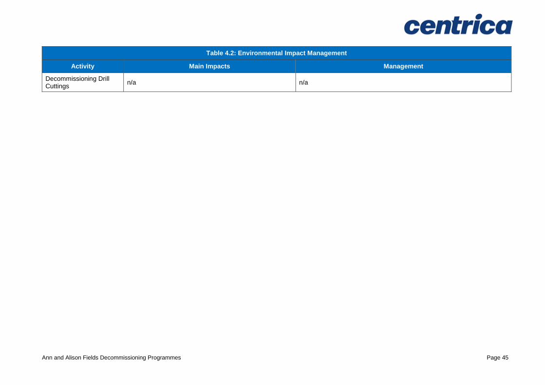
Decommissioning Drill Cuttings
n/a n/a
Ann and Alison Fields Decommissioning Programmes Page 46
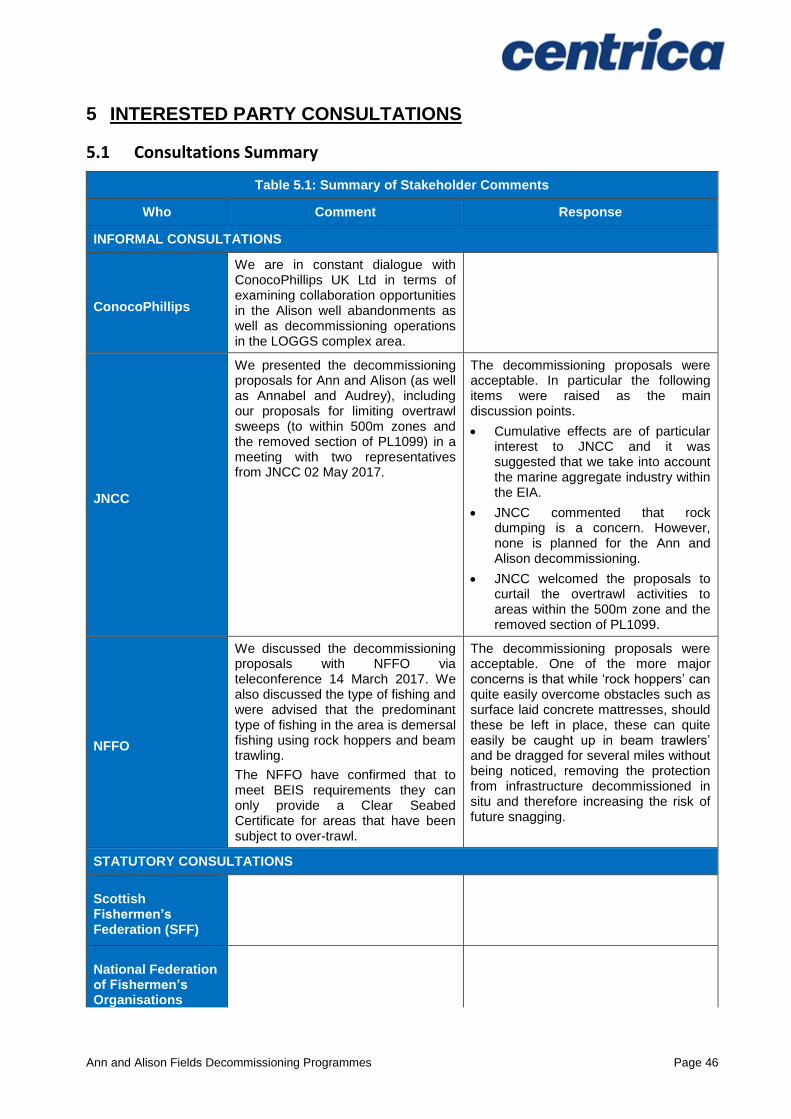
5 INTERESTED PARTY CONSULTATIONS
5.1 Consultations Summary
Table 5.1: Summary of Stakeholder Comments
Who Comment Response
INFORMAL CONSULTATIONS
ConocoPhillips
We are in constant dialogue with ConocoPhillips UK Ltd in terms of examining collaboration opportunities in the Alison well abandonments as well as decommissioning operations in the LOGGS complex area.
JNCC
We presented the decommissioning proposals for Ann and Alison (as well as Annabel and Audrey), including our proposals for limiting overtrawl sweeps (to within 500m zones and the removed section of PL1099) in a meeting with two representatives from JNCC 02 May 2017.
The decommissioning proposals were acceptable. In particular the following items were raised as the main discussion points.
Cumulative effects are of particular interest to JNCC and it was suggested that we take into account the marine aggregate industry within the EIA.
JNCC commented that rock dumping is a concern. However, none is planned for the Ann and Alison decommissioning.
JNCC welcomed the proposals to curtail the overtrawl activities to areas within the 500m zone and the removed section of PL1099.
NFFO
We discussed the decommissioning proposals with NFFO via teleconference 14 March 2017. We also discussed the type of fishing and were advised that the predominant type of fishing in the area is demersal fishing using rock hoppers and beam trawling.
The NFFO have confirmed that to meet BEIS requirements they can only provide a Clear Seabed Certificate for areas that have been subject to over-trawl.
The decommissioning proposals were acceptable. One of the more major concerns is that while ‘rock hoppers’ can quite easily overcome obstacles such as surface laid concrete mattresses, should these be left in place, these can quite easily be caught up in beam trawlers’ and be dragged for several miles without being noticed, removing the protection from infrastructure decommissioned in situ and therefore increasing the risk of future snagging.
STATUTORY CONSULTATIONS
Scottish Fishermen’s Federation (SFF)
National Federation of Fishermen’s Organisations
Ann and Alison Fields Decommissioning Programmes Page 47
Table 5.1: Summary of Stakeholder Comments
Who Comment Response
(NFFO)
Northern Irish Fish Producers Organisation (NIFPO)
Global Marine Systems Limited
Public
Ann and Alison Fields Decommissioning Programmes Page 48
6 PROGRAMME MANAGEMENT
6.1 Project Management and Verification
A Centrica project management team will be appointed to manage the operations of competent contractors selected for all decommissioning activities. The team will ensure the decommissioning is executed safely, in accordance with legislation and Centrica Health and Safety principles. Changes to the Decommissioning Programmes will be discussed with BEIS and any necessary approval sought.
6.2 Post-Decommissioning Debris Clearance and Verification
The Ann and Alison installation sites and the 500m safety zones will be subject to debris and trawlability surveys when decommissioning activities have concluded. Although obliged to carry out trawlability surveys along a 200m wide corridor along all decommissioned pipelines, due to the sensitive nature of the North Norfolk Sandbanks and surrounding area, we would prefer not to carry out trawlability surveys over pipeline areas that have not been subject to decommissioning activities. Given the burial status of the pipelines we would hope that we can agree a practical compromise that satisfies the requirements of the stakeholders concerned.
Any seabed oil and gas debris will be recovered for onshore disposal or recycling in line with existing disposal methods. Independent verification of seabed state will be obtained by trawling the well and pipeline areas and this will be supported by a Certificate of Clearance. This will be included in the Close Out Report and sent to the Seabed Data Centre (Offshore Installations) at the Hydrographic Office.
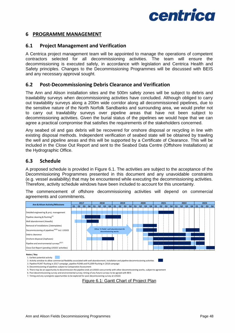
6.3 Schedule
A proposed schedule is provided in Figure 6.1. The activities are subject to the acceptance of the Decommissioning Programmes presented in this document and any unavoidable constraints (e.g. vessel availability) that may be encountered while executing the decommissioning activities. Therefore, activity schedule windows have been included to account for this uncertainty.
The commencement of offshore decommissioning activities will depend on commercial agreements and commitments.
Figure 6.1: Gantt Chart of Project Plan
Q1 Q2 Q3 Q4 Q1 Q2 Q3 Q4 Q1 Q2 Q3 Q4 Q1 Q2 Q3 Q4 Q1 Q2 Q3 Q4 Q1 Q2 Q3 Q4 Q1 Q2 Q3 Q4
Detailed engineering & proj. management
Pipeline cleaning & flushing(3)
Well abandonment (4xwells)
Removal of installations (2xtemplates)
Decommissioning of pipelines(4)(5) incl. LOGGS
Debris clearance
Onshore disposal (2xphases)
Pipeline and environmental surveys(6)(7)
Close Out Report (pending LOGGS' activities)
Notes / Key
1. Earliest potential activity
2. Activity window to allow commercial flexibility associated with well abandonment, installation and pipeline decommissioning activities
3. Pipeline PL947 flushing in 2017 campaign, pipeline PL948 and PL1099 flushing in 2018 campaign
4. Decommissioning of pipelines subject to Comparative Assessment
5. There may be an opportunity to decommission the pipeline ends at LOGGS concurrently with other decommissioning works, subject to agreement
6. Post decommissioning survey and environmental survey; timing of any future surveys to be agreed with BEIS
7. Timing and any synergistic opportunities to be explored for post-decomissioning survey at LOGGS
20232022Ann & Alison Activity/Milestone
2017 2018 2019 2020 2021
Other 'A Fields' well abandonment & decomissioning works
Ann and Alison Fields Decommissioning Programmes Page 49
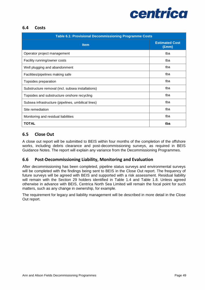
6.4 Costs
Table 6.1: Provisional Decommissioning Programme Costs
Item Estimated Cost
(£mm)
Operator project management tba
Facility running/owner costs tba
Well plugging and abandonment tba
Facilities/pipelines making safe tba
Topsides preparation tba
Substructure removal (incl. subsea installations) tba
Topsides and substructure onshore recycling tba
Subsea infrastructure (pipelines, umbilical lines) tba
Site remediation tba
Monitoring and residual liabilities tba
TOTAL tba
6.5 Close Out
A close out report will be submitted to BEIS within four months of the completion of the offshore works, including debris clearance and post-decommissioning surveys, as required in BEIS Guidance Notes. The report will explain any variance from the Decommissioning Programmes.
6.6 Post-Decommissioning Liability, Monitoring and Evaluation
After decommissioning has been completed, pipeline status surveys and environmental surveys will be completed with the findings being sent to BEIS in the Close Out report. The frequency of future surveys will be agreed with BEIS and supported with a risk assessment. Residual liability will remain with the Section 29 holders identified in Table 1.4 and Table 1.8. Unless agreed otherwise in advance with BEIS, Centrica North Sea Limited will remain the focal point for such matters, such as any change in ownership, for example.
The requirement for legacy and liability management will be described in more detail in the Close Out report.

Ann and Alison Fields Decommissioning Programmes Page 50
7 SUPPORTING DOCUMENTS
Table 7.1: Supporting Documents
Item Document Number Document Title
[1] CEU-DCM-SNS0096-REP-0001 Ann A4 Decommissioning Programme, Jan 2017
[2] CEU-DCM-SNS0096-REP-0007 Ann and Alison Decommissioning Comparative Assessment for Pipelines, April 2017
[3] CEU-DCM-SNS0096-REP-0012 Ann and Alison Decommissioning Environmental Impact Assessment, April 2017
[4] 10786.1 Alison Pre-Decommissioning Survey, Gardline Geosurvey Limited, March 2017
[5] 10786.2 Ann Pre-Decommissioning Survey, Gardline Geosurvey Limited, March 2017
[6] 10786.4 Audrey Pre-Decommissioning Survey, Gardline, Geosurvey Limited, March 2017
Ann and Alison Fields Decommissioning Programmes Page 51
APPENDIX A: PIPELINE BURIAL PROFILES
Appendix A.1 Burial Profile – Pipeline PL947
PL947 is the Ann gas export pipeline that is approximately 41.8km long and routed from the Ann Manifold inside the Ann template through to LOGGS PR Riser Platform. When installed in 1993 the pipeline was trenched. On the approach to the Ann manifold the pipeline was trenched and protected with rock. Approximately half-way along is the Alison tee which has 46m long spool pieces branching from PL947 and connecting the Alison manifold to the main Ann gas export pipeline. We refer to this as the PL947 stub. The Alison tee and enclosed pipeline arrangement is protected and stabilised by steelwork, several large concrete blocks, concrete mattresses, grout bags and deposited rock. As PL947 approaches and exits the Alison tee it is protected and stabilised using rock. The short pipeline stub is laid on the surface and protected by concrete mattresses.
Figure A.1: PL947 burial profile (12” gas export line Ann to LOGGS)12
12
Burial profile of “PL947 stub” which comprises 46m of surface laid pipe spools is not shown
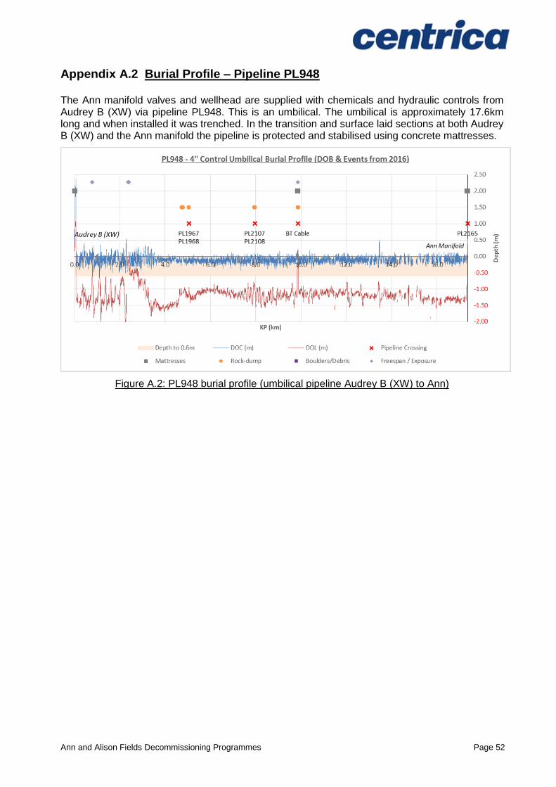
Ann and Alison Fields Decommissioning Programmes Page 52
Appendix A.2 Burial Profile – Pipeline PL948
The Ann manifold valves and wellhead are supplied with chemicals and hydraulic controls from Audrey B (XW) via pipeline PL948. This is an umbilical. The umbilical is approximately 17.6km long and when installed it was trenched. In the transition and surface laid sections at both Audrey B (XW) and the Ann manifold the pipeline is protected and stabilised using concrete mattresses.
Figure A.2: PL948 burial profile (umbilical pipeline Audrey B (XW) to Ann)
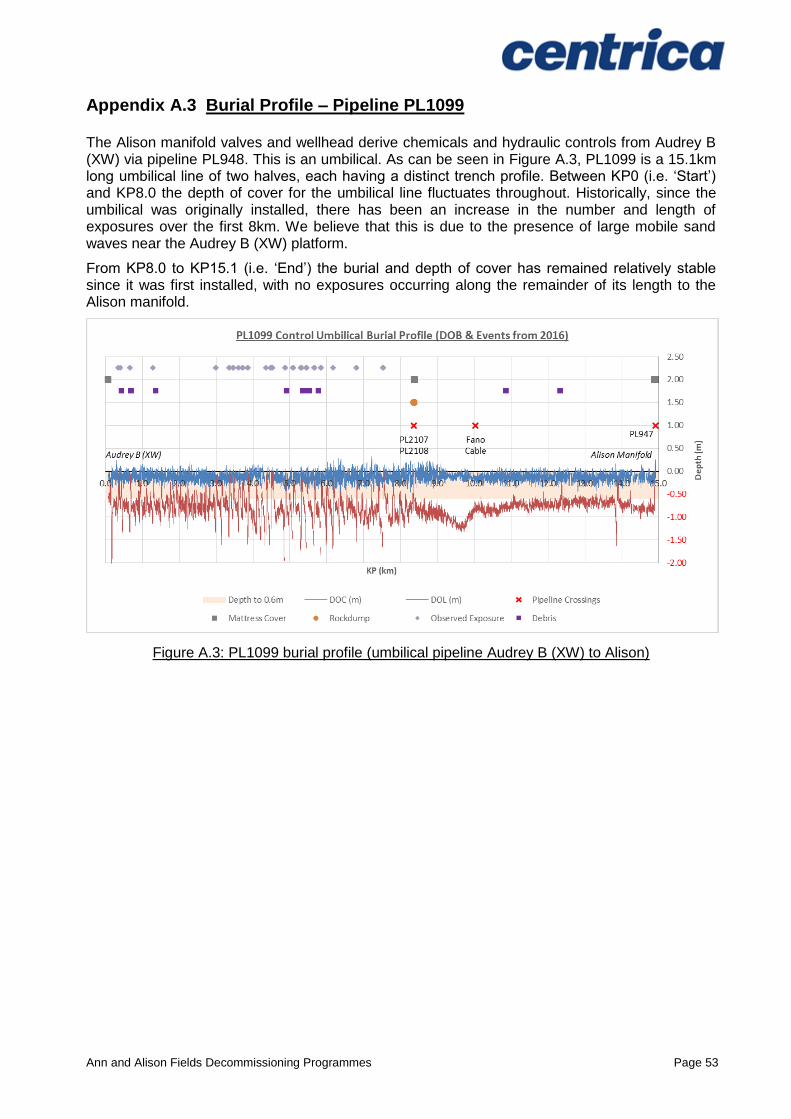
Ann and Alison Fields Decommissioning Programmes Page 53
Appendix A.3 Burial Profile – Pipeline PL1099
The Alison manifold valves and wellhead derive chemicals and hydraulic controls from Audrey B (XW) via pipeline PL948. This is an umbilical. As can be seen in Figure A.3, PL1099 is a 15.1km long umbilical line of two halves, each having a distinct trench profile. Between KP0 (i.e. ‘Start’) and KP8.0 the depth of cover for the umbilical line fluctuates throughout. Historically, since the umbilical was originally installed, there has been an increase in the number and length of exposures over the first 8km. We believe that this is due to the presence of large mobile sand waves near the Audrey B (XW) platform.
From KP8.0 to KP15.1 (i.e. ‘End’) the burial and depth of cover has remained relatively stable since it was first installed, with no exposures occurring along the remainder of its length to the Alison manifold.
Figure A.3: PL1099 burial profile (umbilical pipeline Audrey B (XW) to Alison)

Ann and Alison Fields Decommissioning Programmes Page 54
APPENDIX B: PUBLIC NOTICE & CONSULTEE CORRESPONDENCE
Appendix B.1 Public Notices
HOLD
Appendix B.2 Correspondence
HOLD