Embed Size (px)
Citation preview

ANSTO/T/TN/2015‐20 rev 1
Systems UNCLASSIFIED
Safety and Reliability
ANM Mo99 Facility Operational Risk Assessment
March 2017
ERIS Document Number: TN 148023 rev 1
Systems Safety and Reliability
Engineering and Capital Programs
Australian Nuclear Science and Technology Organisation

RISK ASSESSMENT OF THE ANM FACILITY UNCLASSIFIED ii
ANSTO/T/TN/2015‐20 UNCLASSIFIED March 17
ansto‐t‐tn‐2015‐20 rev 1_anm mo99 facility operational risk assessmentredacted File ADM100421
EngineeringandCapitalPrograms
ANSTO/T/TN/2015‐20 rev 1 ERIS Document Number: TN 148023 rev 1
p:\eng_capex_projects\molybdenum 3000 facility\04 regulatory\01 arpansa submissions\06 operating licence\05 stage 4 licence application\redacted documents\ansto‐t‐tn‐2015‐20 rev 1_anm mo99 facility operational risk assessmentredacted.docx
File ADM100421
Revision History
Revision Date Change
0 05 May 2016 Original issue
1 30 March 2017 Update to include Bulk QC Sample transport package fault scenario
Authorship
Name Position Signature Date
Prepared by
Adviser, Systems Safety and Reliability
Reviewed
Adviser, Systems Safety and Reliability
Authorised
Manager, Systems Safety and Reliability
This report has also been reviewed by the Design Authority and Client Office.

RISK ASSESSMENT OF THE ANM FACILITY UNCLASSIFIED iii
ANSTO/T/TN/2015‐20 UNCLASSIFIED March 17
ansto‐t‐tn‐2015‐20 rev 1_anm mo99 facility operational risk assessmentredacted File ADM100421
EXECUTIVESUMMARYThe ANM Mo99 facility has been built to produce the radioisotope Mo‐99 for use in Australia and overseas. Mo‐99 is used to produce the medical radioisotope Tc‐99m. The Facility is classed as a Nuclear Installation under the ARPANS Act The future operations will involve handling and processing significant quantities of radioactive process materials. This study draws together information on hazards and risks from sources including a series of HAZOP studies covering the hazardous operations. In this report, accidents are postulated and analysed for the facility. The risks of these accident scenarios have also been determined.
A brief description of the ANM Facility High Activity Handling Cells facility and operations is provided. Safety features in the facility are described where they are relevant to determining the credibility of postulated accidents.
The analysis involved personnel from Systems Safety and Reliability (SSR) and personnel with specific knowledge of the facility operations from current Mo‐99 Operations. The process was divided into logical elements for which potential accident scenarios were determined, the likelihood and consequence of each scenario assessed, and risk level determined, according to AG‐2395 guidance. Security and business risks are managed through other processes and are not discussed in this report.
Consistent with our graded approach, in the main body of the document the risk assessment was undertaken quantitatively for radiological fault sequences whose consequences were assessed to be major or more severe or where doses to members of the public could exceed 1 mSv. All other fault sequences have been included in an appendix for completeness of all postulated operational identified faults, some of which were assessed semi‐quantitatively using engineering judgement.
The risks considered in this report were assessed taking into account satisfactory implementation of the recommendations. Therefore, since this report is intended (amongst other uses) to support ANSTO internal safety approval of the proposed ANM Facility operations, it is expected that the client will prepare a document outlining the disposition of these recommendations. The disposition of the recommendations should be made in consultation with the author(s) of this report.
The result of this operational safety assessment will support the facility Safety Assessment Report (SAR) that is included with the ANM Mo99 operations licence application.

RISK ASSESSMENT OF THE ANM FACILITY UNCLASSIFIED iv
ANSTO/T/TN/2015‐20 UNCLASSIFIED March 17
ansto‐t‐tn‐2015‐20 rev 1_anm mo99 facility operational risk assessmentredacted File ADM100421
CONTENTS
EXECUTIVESUMMARY................................................................................................................................................iii
1. INTRODUCTION...............................................................................................................................................1
2. BACKGROUND...................................................................................................................................................1
3. SCOPE..................................................................................................................................................................1
3.1 OBJECTIVES..............................................................................................................................................................................2
4. BUILDINGS,PLANTANDMAJOREQUIPMENT........................................................................................2
4.1 BUILDING..................................................................................................................................................................................3 4.2 HOTCELLS.................................................................................................................................................................................3 4.2.1 Hotcellfeatures...................................................................................................................................................................4 4.2.2 PressureReliefDevice......................................................................................................................................................6
4.3 ACTIVEVENTILATIONSYSTEM.............................................................................................................................................7 4.3.1 Red/Primary(RP)ExhaustSystem............................................................................................................................7 4.3.2 SecondaryVentilationSystems.................................................................................................................................11 4.3.3 SupplyAirSystems..........................................................................................................................................................12 4.3.4 StackDischarge................................................................................................................................................................13 4.3.5 Majorsubsystems,subassembliesandcomponentsoftheAVS..................................................................13
4.4 PROCESSCONTAINMENT.....................................................................................................................................................17 4.4.1 DissolverVessels...............................................................................................................................................................17 4.4.2 FilterforUO2precipitate.............................................................................................................................................18 4.4.3 FiltrateCollectionVessel..............................................................................................................................................18 4.4.4 GasManagementVessel...............................................................................................................................................18 4.4.5 HydrogenConverters.....................................................................................................................................................18 4.4.6 Condenserandtheassociatedwatercoolingsystem......................................................................................18 4.4.7 Gasdecaytanks................................................................................................................................................................18 4.4.8 Dedicatedgastankforpressurerelief...................................................................................................................19 4.4.9 Burstingdiscs....................................................................................................................................................................19 4.4.10 Inletandoutletvalvesofthegasdecaytanks....................................................................................................19 4.4.11 PressureandTemperaturetransducersandtransmittersassociatedwithcontroland
protection...........................................................................................................................................................................19 4.5 FLASKS...................................................................................................................................................................................20 4.5.1 TargetTransferFlask....................................................................................................................................................20 4.5.2 SUFCupFlask....................................................................................................................................................................20 4.5.3 RetrievableWasteFlask...............................................................................................................................................21 4.5.4 HorizontalTransferCask.............................................................................................................................................21
4.6 CRANESUBSYSTEMS,ANDCOMPONENTSANDOPERATIONS........................................................................................22 4.6.1 RearoftheCellcrane.....................................................................................................................................................23 4.6.2 LightCranes.......................................................................................................................................................................24 4.6.3 MonorailCranes...............................................................................................................................................................25 4.6.4 WallMountedJibCranes..............................................................................................................................................25 4.6.5 PackingCellfixedhoist.................................................................................................................................................26
4.7 SAFETYINTERLOCKS...........................................................................................................................................................26 4.7.1 HydrogenLeakDetectionAlarms............................................................................................................................26 4.7.2 Interlocksthatcontroltransferofradioactivematerialbetweenshieldedflasksandhotcells..27 4.7.3 SafetyInterlocksfortheB(U)PortinthePackagingHotcell......................................................................30 4.7.4 ControlandinterlockingfunctionsoftheAVSrelatedtoProcessContainment................................34 4.7.5 ControlandinterlocksandalarmsoftheProcessControlSystem...........................................................34
4.8 RADIATIONANDCONTAMINATIONMONITORINGANDALARMS....................................................................................35 4.8.1 RadiationMonitorsusedforSafetyInterlockingand/orAlarms..............................................................39
5. SUMMARYOFOPERATIONS......................................................................................................................41

RISK ASSESSMENT OF THE ANM FACILITY UNCLASSIFIED v
ANSTO/T/TN/2015‐20 UNCLASSIFIED March 17
ansto‐t‐tn‐2015‐20 rev 1_anm mo99 facility operational risk assessmentredacted File ADM100421
5.1 OPERATIONSOUTSIDETHEFACILITYBUILDING..............................................................................................................41 5.2 TRANSPORTOFTARGETSFROMB80TOANM..............................................................................................................41 5.3 OPERATIONSINTHEREAROFCELLSAREA.......................................................................................................................42 5.4 OPERATIONSINOTHERGROUNDFLOORAREAS..............................................................................................................42 5.5 OPERATIONSINTHEBASEMENT........................................................................................................................................42 5.6 ACTIVELIQUIDWASTESYSTEM..........................................................................................................................................42 5.7 MEZZANINELEVELPLANTROOMS.....................................................................................................................................43
6. SUMMARYOFPROCESS..............................................................................................................................43
6.1 MO‐99PROCESS..................................................................................................................................................................43 6.2 HOTCELLOPERATIONS........................................................................................................................................................44 6.2.1 ProductionHotcellStages...........................................................................................................................................44 6.2.2 SupportServicesHotcells.............................................................................................................................................46 6.2.3 ValvesofDissolverandHydrogenconverter......................................................................................................47
6.3 MAINPRODUCTIONAREAS................................................................................................................................................49 6.3.1 ProductionCellFace(andProductionHotcells)...............................................................................................49 6.3.2 RearofCell.........................................................................................................................................................................49 6.3.3 RearofCellMezzanineLevel......................................................................................................................................49 6.3.4 Despatch..............................................................................................................................................................................49 6.3.5 TruckAirLock..................................................................................................................................................................49
6.4 OTHERPRODUCTIONAREAS..............................................................................................................................................50 6.4.1 Receipting...........................................................................................................................................................................50 6.4.2 ProductionStorage(andQuarantine)...................................................................................................................50 6.4.3 IntermediatePreparation...........................................................................................................................................50 6.4.4 ProcessQuarantineandProcessRelease.............................................................................................................50 6.4.5 ProcessPreparationLaboratories...........................................................................................................................51 6.4.6 AssemblyandTestArea................................................................................................................................................51 6.4.7 ContainerHandling&Cleaning................................................................................................................................51
6.5 UTILITYSERVICES................................................................................................................................................................51 6.5.1 PurifiedWaterSystems................................................................................................................................................51 6.5.2 PurifiedNitrogenGas....................................................................................................................................................52 6.5.3 CompressedAir.................................................................................................................................................................52 6.5.4 Electrical.............................................................................................................................................................................52
6.6 QUALITYCONTROLAREAS.................................................................................................................................................52 6.6.1 QC(Active)ChemicalandInstrumentLaboratoryatB2..............................................................................52 6.6.2 SamplingTestLaboratory...........................................................................................................................................52
6.7 WASTEREMOVAL................................................................................................................................................................52 6.7.1 SolidWaste.........................................................................................................................................................................52 6.7.2 LiquidWaste......................................................................................................................................................................53 6.7.3 GaseousWaste..................................................................................................................................................................53
7. APPROACH......................................................................................................................................................53
7.1 STUDYINPUT.........................................................................................................................................................................53 7.2 RISKASSESSMENT................................................................................................................................................................54
8. DISCUSSION....................................................................................................................................................54
8.1 ANALYSISOFPOSTULATEDACCIDENTS.............................................................................................................................54 8.1.1 Droppingthetransportflaskcontainingactivematerialintheloadingbay......................................54 8.1.2 Redprimaryexhaustventilationfailureduringanaccidentalreleaseofradioactivityintoany
oftheproductionhotcells............................................................................................................................................55 8.1.3 DroppingMo‐99productcontainerthroughtheB(U)portdoorwithoutaB(U)ICdockedinthe
B(U)portofthepackagingcell.................................................................................................................................56 8.1.4 OperatoropensthemaintenanceaccessdoorofthePackagingCellwithoutfirstensuringthat
thereisnosignificantradioactivityinside...........................................................................................................56 8.1.5 Damagetoprocesstanksorpipingduetoaseismicevent..........................................................................57

RISK ASSESSMENT OF THE ANM FACILITY UNCLASSIFIED vi
ANSTO/T/TN/2015‐20 UNCLASSIFIED March 17
ansto‐t‐tn‐2015‐20 rev 1_anm mo99 facility operational risk assessmentredacted File ADM100421
8.1.6 SeismicFailureofDecayTanks.................................................................................................................................57 8.1.7 SeismicFailureoftheLiquidWasteHoldingTanks........................................................................................58
8.2 INDUSTRIALHAZARDS.........................................................................................................................................................58 8.2.1 Accidentalcontactwithelectricalterminals......................................................................................................58 8.2.2 Workerfallingduringmaintenanceandoperations......................................................................................58 8.2.3 Fire/explosionintheGasCylinderStore.............................................................................................................59
8.3 REFERENCEACCIDENT........................................................................................................................................................59
9. CONCLUSIONS................................................................................................................................................60
10. RECOMMENDATIONS..................................................................................................................................60
11. REFERENCES..................................................................................................................................................61
APPENDIXA‐INPUTSTUDIES................................................................................................................................63
APPENDIXB‐SAFETYASSESSMENTRISKASSESSMENTSUMMARYTABLES..........................................65
APPENDIXC‐FAILURESDURINGPROCESSOPERATIONS.............................................................................95
APPENDIXD‐CONSEQUENCEASSESSMENTOFANUNSPECIFIEDENERGETICEVENT.......................137
APPENDIXE‐RISKMATRIX(RISKEVALUATIONTABLES).........................................................................140
RISK ASSESSMENT OF THE ANM FACILITY UNCLASSIFIED 1
ANSTO/T/TN/2015‐20 UNCLASSIFIED March 17
ansto‐t‐tn‐2015‐20 rev 1_anm mo99 facility operational risk assessmentredacted File ADM100421
1. INTRODUCTIONThe ANM Mo99 facility has been built to produce the isotope molybdenum99 (Mo‐99) for use in Australia and overseas. Mo‐99 is used to produce the medical isotope Tc‐99m. The operations will involve transport of radioactive targets and waste materials, crane and vehicle movements, hotcell processes, packaging and despatch, management of liquid wastes and control of emissions.
The Mo‐99 Production Process in the Facility is the chemical process used for the separation and purification of Mo‐99 from other fission products produced by the irradiation of Low Enriched Uranium (LEU) targets in OPAL.
This study draws together information on hazards and safety events from several sources including hazard and operability (HAZOP) studies and an evaluation of the potential effects of external natural and man‐made hazards.
The ANSTO risk assessment process (AG‐2395) is used to evaluate the acceptability of these risks.
The results from this assessment will support the facility’s Safety Analysis Report (SAR), which will be included with the operation licence application to ARPANSA.
2. BACKGROUNDThe ANSTO site is located on the southern side of New Illawarra Rd, Lucas Heights. The ANM Mo99 facility is located in the area known as the Reactor Precinct on the western side of the site in close proximity to the existing OPAL reactor and the future Synroc Facility.
Mo‐99 Operations produces Molybdenum‐99, which is used by ANSTO Health and other customers to produce technetium generators where the Mo‐99 decays to Tc‐99m used in medical imaging.
Mo‐99 is produced by the fission of Uranium‐235. The process in the Facility is used to separate the Mo‐99 from the other fission products produced during irradiation. The Mo‐99 process is based upon the process used by NTP Radioisotopes SOC Ltd. The process design will be largely based upon the process used by NTP, but will also include significant technology used in the existing ANSTO plant.
The main purpose of the report is to document the main risk assessment for the facility.
Under the ARPANS Act, the ANM Facility is designated as a "Nuclear Installation", a type of a Controlled Facility. The ARPANSA Regulatory Assessment Principles (ARPANSA 2001) require that all controlled facilities be assigned Hazard Categories in order to determine the appropriate level of review and approval. The SAPs define the Hazard Categories qualitatively as follows:
Hazard Category F1: where there is no potential for significant consequences outside the nuclear facility;
Hazard Category F2: where there is potential for significant consequences outside the nuclear facility, but not outside the site; and
Hazard Category F3: where there is potential for significant consequences outside the site.
For the purpose of this categorisation process, ANSTO has interpreted, "significant consequences" outside the site as the possibility of radiological exposure to members of the public in excess of 5 mSv (being the level at which sheltering should be considered) and "significant consequences" on site are taken as 15 mSv, being ANSTO’s self‐imposed general dose constraint. Common practice at nuclear installations around the world, higher levels of on‐site exposure are considered acceptable than that which may be involuntarily received off‐site. Various levels used elsewhere for on‐site exposure are typically, 50 mSv. Such exposure may arise because of either direct radiation or the uncontrolled release of radioactive material to the environment.
3. SCOPEThe scope of this safety assessment includes the hazardous activities associated with the operation of the ANM Mo99 facility, with the exceptions discussed below. The source documents providing the inputs on operational events and accidents are listed in Appendix A.
Excluded from the scope of this study are:
Activities performed under other ANSTO licences. The licence interface points between ANM Mo99 operations and other ANSTO licences are listed in the table below.

RISK ASSESSMENT OF THE ANM FACILITY UNCLASSIFIED 2
ANSTO/T/TN/2015‐20 UNCLASSIFIED March 17
ansto‐t‐tn‐2015‐20 rev 1_anm mo99 facility operational risk assessmentredacted File ADM100421
WHS hazards for staff working in areas that are classified radiologically as white contamination / white radiation.
Security risks have been assessed in a separate report and are excluded from this report.
High‐level business and project risks are being managed under the ANSTO risk process and are excluded here.
The interfaces between the ANM Mo99 operations and other licensed operations are given in the table.
Table 1 Interface Licence
Interface Activity Interface Licence
Receipt of targets in flask in OPAL (B80) loading dock ARPANSA licence
F0157 OPAL
Removal of packaged SUF cups from solid waste hotcell, loading into flask and movement to Waste Operations (B41)
ARPANSA licence
F0260 Waste Operations
Discharge of emissions to atmosphere ARPANSA discharge authorisation
Removal of liquid waste to Waste Operations ARPANSA licence
F0260 Waste Operations
Removal of ILLW F0266 SyMo Facility(Siting and construction)
Removal of LLLW F0260 Waste Operations
The main working areas of this nuclear installation are the hotcells together with the associated cell faces, rear of cell area and cell roof area. There is also a receipt/dispatch bay through which the activated targets and end product pass, an electrical switchgear and ventilation plant room, a decontamination area and general office and storage areas. The movement of targets from Building 80 and product to the ANM Facility is covered in the analysis. All other interface operations (such as Waste Operations Activities, Environmental Liquid Waste Store tank, etc.) will be captured within the Facility’s Safety Analysis Report.
This report covers the risks associated with internal abnormal events that could occur due to equipment failures and/or human error and internal initiators such as fire, as well as the consequence of the external event of an earthquake. Operational procedures are currently in production detailing activities to be undertaken within ANM, these will be reviewed at a later to assess any additional operating risks.
The analysis of normal (routine) operations dose of the facility is not included in this study and is part of a separate study (Polweski, 2015).
Criticality accidents are outside the scope of this document. Separate criticality assessments have been performed by Nuclear Analysis (ANSTO/CCA/056). These finding will be summarised in the Facility’s SAR. In the event there are changes to the operating regime a review of this assessment and the criticality certificate will be required.
3.1 ObjectivesThe objective of this document is to assess the safety of the proposed operation of the ANM Mo99 facility. A further objective is to make recommendations where needed to confirm the assessment and enhance safety.
The results of this assessment will support the safety case for the facility and is part of the operation licence application.
4. BUILDINGS,PLANTANDMAJOREQUIPMENTThis section of the document describes the systems that will be used in the facility for the building including heating, ventilation and air conditioning (HVAC), electrical power, water, drainage, compressed gases, communications, radioactive waste storage, non‐radioactive waste storage, hotcells and Mo‐99 processing plant.

RISK ASSESSMENT OF THE ANM FACILITY UNCLASSIFIED 3
ANSTO/T/TN/2015‐20 UNCLASSIFIED March 17
ansto‐t‐tn‐2015‐20 rev 1_anm mo99 facility operational risk assessmentredacted File ADM100421
4.1 BuildingThe ANM Mo99 facility is designed with three floor levels with the functions described below.
Ground floor
The ground floor is the main processing area. It also has the main pedestrian entrance and staff access to all areas. The layout is shown in Error! Reference source not found..
Truck airlock (flask receipt and despatch).
Rear of Cells (process service and maintenance).
Front of Cells (process, production of Mo‐99 in hotcells).
Sample Cell / Valves (control / testing for ILLW & LLLW tanks).
Container handling Despatch.
QC and Sample Laboratories.
Change rooms (clothing and PPE for access to active areas).
Ground level plant room housing main switchboards and active exhaust fans, filters and stack to treat, dilute and discharge exhaust air.
Several cranes.
Hatch to basement.
Storage and other areas.
Truck bay for deliveries.
At ground level, there is an external service yard and gas store. The ILLW and LLLW tanks and bund / shielding enclosures are on the north side of the building.
Basement
The basement level is designed for handling the active waste streams and will not require significant routine staff access to maintain. The layout is shown in Error! Reference source not found.. The main areas and functions are:
Gaseous waste treatment (Active ventilation ‐ SIAM filters, Carbon Column, Gas Delay Tanks).
Active exhaust system.
Liquid waste transfer (initial capture and delay with subsequent transfer from holding tanks to decay tanks).
Truck airlock (maintenance access and waste flask collection).
Mezzanine level
The area over the rear of cells is double height i.e. to building ceiling. The layout is shown in Error! Reference source not found.. The mezzanine floor areas have the following functions:
Rear of Cells Mezzanine (access to top of hotcells, storage, floor hatch through to truck airlock below).
Mezzanine Plant Room for I&C, UPS, Communications, Hydraulics, and Mechanical plant and equipment.
The office areas and staff amenities are on a first floor level to the east of the operating areas.
4.2 HotcellsThe ANM Mo99 building floor space and layout has provision for two production lines. The duplicated hotcells and equipment provide higher levels of reliability for production but are not necessary to achieve the production throughputs.
The following descriptions and information are for the two lines of production:
Production Hotcells: (6 hotcells + 1 unused)
RISK ASSESSMENT OF THE ANM FACILITY UNCLASSIFIED 4
ANSTO/T/TN/2015‐20 UNCLASSIFIED March 17
ansto‐t‐tn‐2015‐20 rev 1_anm mo99 facility operational risk assessmentredacted File ADM100421
DCELL1 – Dissolution Hotcell, in which the irradiated targets are dissolved and the solution is run through columns.
HCELL – The hotcell containing the hydrogen converter and its regeneration.
DCELL2 – Future provision for a second dissolution cell (not utilised presently).
PCELL1 – Purification Cell.
ECELL1 – Evaporation Cell.
DSPC1 –Dispensing Hotcell.
PKGC1 – Packaging Hotcell.
These are laid out with a single hydrogen conversion hotcell in the centre and the second line laid out in the opposite direction
Service Hotcells: (6 service hotcells + 1 for the waste tank system)
Maintenance Hotcell – future provision.
In Process Sampling Hotcell.
ILWS Hotcell – Intermediate Level Solid Wastes – handling.
LLWS Hotcell – Low Level Solid Waste.
Liquid Waste Sampling Hotcell.
MPB/IPC Hotcell – future provision
Waste Tank Vacuum Pump Exhaust Hotcell.
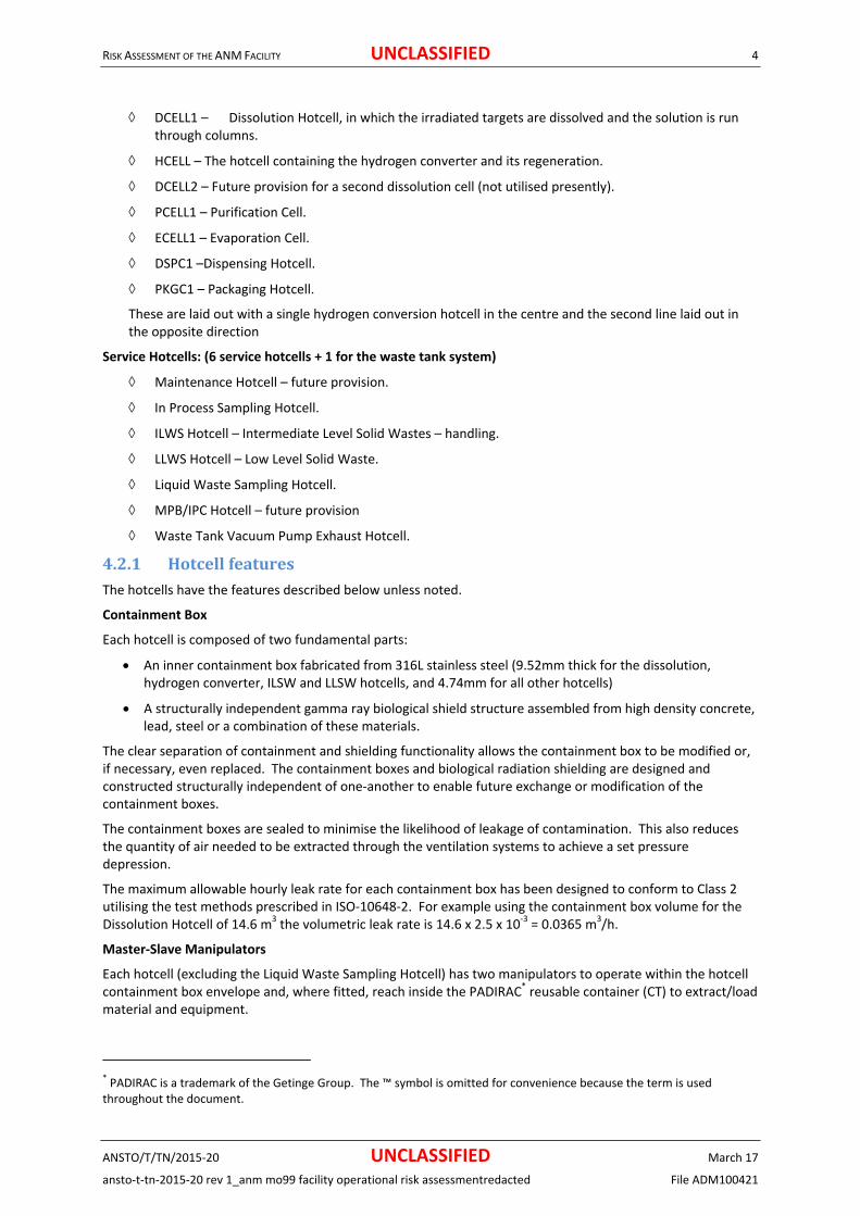
4.2.1 HotcellfeaturesThe hotcells have the features described below unless noted.
Containment Box
Each hotcell is composed of two fundamental parts:
An inner containment box fabricated from 316L stainless steel (9.52mm thick for the dissolution, hydrogen converter, ILSW and LLSW hotcells, and 4.74mm for all other hotcells)
A structurally independent gamma ray biological shield structure assembled from high density concrete, lead, steel or a combination of these materials.
The clear separation of containment and shielding functionality allows the containment box to be modified or, if necessary, even replaced. The containment boxes and biological radiation shielding are designed and constructed structurally independent of one‐another to enable future exchange or modification of the containment boxes.
The containment boxes are sealed to minimise the likelihood of leakage of contamination. This also reduces the quantity of air needed to be extracted through the ventilation systems to achieve a set pressure depression.
The maximum allowable hourly leak rate for each containment box has been designed to conform to Class 2 utilising the test methods prescribed in ISO‐10648‐2. For example using the containment box volume for the Dissolution Hotcell of 14.6 m3 the volumetric leak rate is 14.6 x 2.5 x 10‐3 = 0.0365 m3/h.
Master‐Slave Manipulators
Each hotcell (excluding the Liquid Waste Sampling Hotcell) has two manipulators to operate within the hotcell containment box envelope and, where fitted, reach inside the PADIRAC* reusable container (CT) to extract/load material and equipment.
* PADIRAC is a trademark of the Getinge Group. The ™ symbol is omitted for convenience because the term is used throughout the document.

RISK ASSESSMENT OF THE ANM FACILITY UNCLASSIFIED 5
ANSTO/T/TN/2015‐20 UNCLASSIFIED March 17
ansto‐t‐tn‐2015‐20 rev 1_anm mo99 facility operational risk assessmentredacted File ADM100421
The manipulators used in the larger volume concrete hotcells (dissolution, hydrogen converter, and solid waste management hotcells) are power assisted. Mechanical master‐slave manipulators are used on all the smaller volume hotcells with the exception of the Liquid Waste Sampling hotcell, which uses tong‐ball manipulators instead.
The hotcell containment boundary is maintained around the manipulators by means of a plastic sleeve or booting, sealed to the hotcell containment box on one end, and the manipulator hand at the other. This booting stays within the cell during manipulator changes, to maintain the integrity of the containment boundary at all times. The booting itself can also be changed without compromising the cell containment boundary.
PADIRAC System
The movements of materials to and from the production and service hotcells will use the proprietary PADIRAC flask system.
The PADIRAC system comprises two parts, the shielded flask system known as the PADIRAC and the sealed double door system known as the DPTE† 270 Transfer System. The PADIRAC system is a reliable, simple solution for moving equipment / materials / waste into or out of any Alpha, Beta or Gamma containment while maintaining confinement, and with full protection against radiation. The PADIRAC system is used throughout the world, with over 170 systems in use in 2013.
The PADIRAC transfer system will be used for a variety of tasks including loading production materials into the cells and the removal of waste from the cells. The Getinge‐La Calhène DPTE 270 Transfer System docking port is incorporated on all cells other than the Liquid Waste Sampling Cell. The Packaging Cell, while having a DPTE 270 door system, does not have the capability to work with the PADIRAC flask and the DPTE door is used solely for maintenance activities after the rear hotcell shielded access door has been opened. Two types of DPTE door system are used with the hotcells. The Dissolution, Hydrogen, Purification, Evaporation, Dispensing, Intermediate Waste and Low Level Waste Hotcells all used pneumatically operated DPTE doors. These doors incorporate a mechanical and electrical interlock that prevents opening the containment box door unless the DPTE container is engaged and locked with the cell (see Section 4.7). The Packaging Hotcell, which does not interface with the PADIRAC Flask, uses a manually operated DPTE door. This door uses a mechanical interlock to prevent opening of the containment door until the DPTE container is engaged and locked with the cell.
Biological Shielding
The biological shielding is designed to meet the ANSTO radiological requirements, which in turn satisfy the regulatory requirements. The source terms and geometries have been developed and documented (Alam 2013). The shielding design has been confirmed by:
The safety assessments developed and submitted under ARPANS Regulation 54 (see APPENDIX A for list of input studies).
The cold commissioning tests using sealed sources and the hot commissioning tests that will be undertaken as per the commissioning schedule which will be produced.
The biological shielding is designed to achieve the following dose attenuation:
Maximum dose rate at contact on front of cell surfaces: 0.003 mSv/h.
Maximum dose rate at contact on rear of cell surfaces: 0.01 mSv/h.
Main Doorway Access
Each cell has been designed and built to have an access doorway for reaching the containment box. The containment box can be removed from the cell although it is not anticipated this will be necessary in the life of the facility.
Viewing Windows
Each hotcell has a front of cell viewing window that provides equivalent radiological protection to the biological shielding with comfortable viewing for all volumes needed for operation.
† DPTE is a registered trademark of the Getinge Group. The ® symbols are omitted for convenience because the term is used throughout the document.

RISK ASSESSMENT OF THE ANM FACILITY UNCLASSIFIED 6
ANSTO/T/TN/2015‐20 UNCLASSIFIED March 17
ansto‐t‐tn‐2015‐20 rev 1_anm mo99 facility operational risk assessmentredacted File ADM100421
Lighting
There is lighting within the containment boxes, and the tubes/bulbs can be changed without breaking containment.
Cameras
There are video connections within each containment box to allow for the connection of a camera in‐cell to assist with any maintenance or inspection activities. The display screen will be at the cell front.
Vacuum break devices
Two types of vacuum break devices are available in the Active Ventilation System (AVS) piping to prevent excessive negative pressure in the hotcell containment and possible implosion damage.
Manometer type vacuum breaker device using a column of hydraulic oil.
Mechanical type using a reliable gravity or spring ‐operated mechanism.
The vacuum break setting will be around ‐2.5kPa (AVS Drawing 3111_F Sheet 1), which would then allow a margin of safety (around 1.3 to 2.4) against implosion damage to hotcell containment. The actual settings will be determined during commissioning tests.
These devices will be located in the basement and rear hotcells area.
The dissolution cell (DCELL) will have both types of vacuums break devices as a diverse and redundant pair installed on the inlet and outlet pipes of the cell,
The purification cell will have a mechanical type vacuum breaker on the outlet pipes of AVS.
The hydrogen conversion cell will have a manometer type vacuum breaker on the outlet pipes of AVS so that it could act as both a vacuum breaker device as well as pressure relief device.
The AVS branch headers for RP3 and RP4 Red primary exhaust will each have mechanical type vacuum breaker device, so that each of the hotcells connected to these headers will be protected against excess negative pressure.
The following table shows the vacuum break devices that would protect the various hotcell containment boxes.
Table 2 Details of vacuum break devices for the hotcells
Hotcell Location of vacuum breaker
Type of vacuum breaker
Maximum design negative pressure of hotcell containment
Provisional vacuum break
setting
DCELL DCELL inlet Mechanical type ‐3.4kPa ‐2.5kPa
DCELL outlet Manometer type ‐2.5kPa
HCELL HCELL outlet Manometer type ‐3.4kPa ‐2.5kPa
PCELL PCELL Mechanical type or Manometer Type
‐6.0kPa ‐2.5kPa
ILSW and LLSW hotcells (concrete)
RP4 header Mechanical type or Manometer Type
‐3.4kPa ‐2.5kPa
All other production and service hotcells (lead hotcells)
RP3 or RP 4 header
Mechanical type or Manometer Type
‐6.0kPa ‐2.5kPa
4.2.2 PressureReliefDeviceThe manometer type vacuum breaker described above will also function effectively as a pressure relief device against potential positive pressure in the hotcell containment. Such pressure relief devices will be provided for the Dissolution Cell (DCELL) and the hydrogen conversion cell (HCELL) where there are significant heat sources either due to heating or due to decay of radioactive sources and hence the potential for pressure build up under abnormal conditions.
RISK ASSESSMENT OF THE ANM FACILITY UNCLASSIFIED 7
ANSTO/T/TN/2015‐20 UNCLASSIFIED March 17
ansto‐t‐tn‐2015‐20 rev 1_anm mo99 facility operational risk assessmentredacted File ADM100421
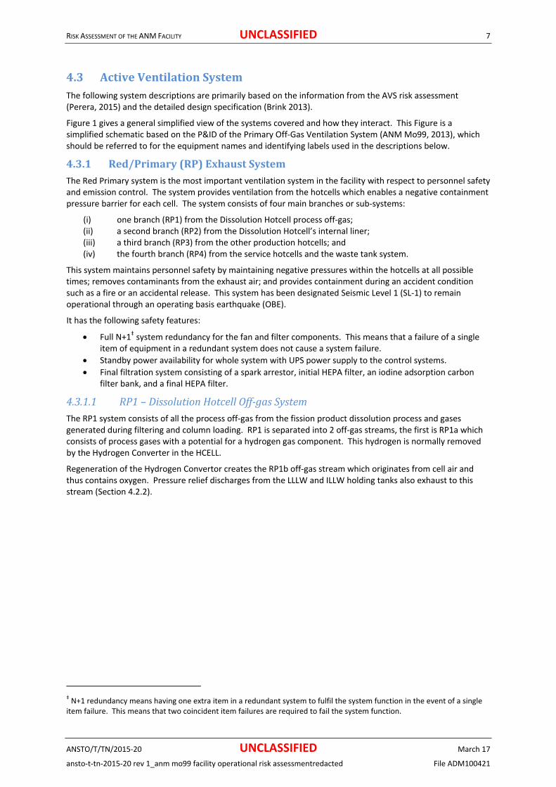
4.3 ActiveVentilationSystemThe following system descriptions are primarily based on the information from the AVS risk assessment (Perera, 2015) and the detailed design specification (Brink 2013).
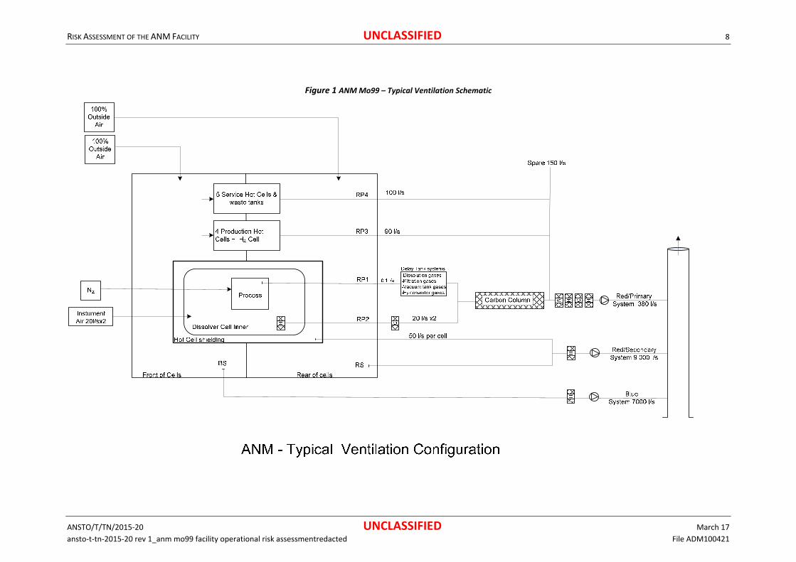
Figure 1 gives a general simplified view of the systems covered and how they interact. This Figure is a simplified schematic based on the P&ID of the Primary Off‐Gas Ventilation System (ANM Mo99, 2013), which should be referred to for the equipment names and identifying labels used in the descriptions below.
4.3.1 Red/Primary(RP)ExhaustSystemThe Red Primary system is the most important ventilation system in the facility with respect to personnel safety and emission control. The system provides ventilation from the hotcells which enables a negative containment pressure barrier for each cell. The system consists of four main branches or sub‐systems:
(i) one branch (RP1) from the Dissolution Hotcell process off‐gas; (ii) a second branch (RP2) from the Dissolution Hotcell’s internal liner; (iii) a third branch (RP3) from the other production hotcells; and (iv) the fourth branch (RP4) from the service hotcells and the waste tank system.
This system maintains personnel safety by maintaining negative pressures within the hotcells at all possible times; removes contaminants from the exhaust air; and provides containment during an accident condition such as a fire or an accidental release. This system has been designated Seismic Level 1 (SL‐1) to remain operational through an operating basis earthquake (OBE).
It has the following safety features:
Full N+1‡ system redundancy for the fan and filter components. This means that a failure of a single item of equipment in a redundant system does not cause a system failure.
Standby power availability for whole system with UPS power supply to the control systems.
Final filtration system consisting of a spark arrestor, initial HEPA filter, an iodine adsorption carbon filter bank, and a final HEPA filter.
4.3.1.1 RP1–DissolutionHotcellOff‐gasSystemThe RP1 system consists of all the process off‐gas from the fission product dissolution process and gases generated during filtering and column loading. RP1 is separated into 2 off‐gas streams, the first is RP1a which consists of process gases with a potential for a hydrogen gas component. This hydrogen is normally removed by the Hydrogen Converter in the HCELL.
Regeneration of the Hydrogen Convertor creates the RP1b off‐gas stream which originates from cell air and thus contains oxygen. Pressure relief discharges from the LLLW and ILLW holding tanks also exhaust to this stream (Section 4.2.2).
‡ N+1 redundancy means having one extra item in a redundant system to fulfil the system function in the event of a single item failure. This means that two coincident item failures are required to fail the system function.
RISK ASSESSMENT OF THE ANM FACILITY UNCLASSIFIED 8
ANSTO/T/TN/2015‐20 UNCLASSIFIED March 17
ansto‐t‐tn‐2015‐20 rev 1_anm mo99 facility operational risk assessmentredacted File ADM100421
Figure 1 ANM Mo99 – Typical Ventilation Schematic

RISK ASSESSMENT OF THE ANM FACILITY UNCLASSIFIED 9
ANSTO/T/TN/2015‐20 UNCLASSIFIED March 17
ansto‐t‐tn‐2015‐20 rev 1_anm mo99 facility operational risk assessmentredacted File ADM100421
RP1a – Dissolution Hotcell Off‐gas System (with potential H2)
The RP1a off‐gas system removes gaseous waste from the dissolving and filtering processes and from the general localised vacuum off‐gas, directing it, via vacuum, to decay tanks for a defined storage period and then discharging via vacuum pump systems into the Red Primary (RP2) ventilation system.
The RP1a consists of 3 vacuum tank/pump systems. The first takes dissolution gases from the hydrogen converters. The second takes off‐gas from the filtering and column loading processes. The third takes off‐gas from a vacuum buffer exhaust line providing localised off‐gas exhaust from dedicated vacuum tanks. These tanks are prepared for each particular off‐gas operation prior to the start of a dissolving run to ensure availability of vacuum for capturing all gaseous contaminants from the dissolving and associated processes.
The vacuum tanks draw the off‐gas from the processes or process vessels as required. The captured off‐gas is then isolated for a pre‐determined period to provide the required decay. These delays are 7 weeks for the Dissolution Hotcell off‐gas, 2 weeks for the filtration off‐gas and minimal delay for the vacuum buffer tank system.
After this decay period the particular vacuum tank/s may be pumped out into the RP2 ventilation sub‐system through the carbon columns system providing further retention and decay. The vacuum pumps have full automatic duty/standby operation with current monitoring with alarms being raised if a vacuum pump fails or monitors exceed defined limits. The vacuum pumps are interlocked with in line moisture eliminators and moisture detectors.
Control interlocks/alarms prevent a tank being made available for the batch process until a pressure hold test is undertaken and the prescribed vacuum is drawn. An alarm is raised if the vacuum tank pressure rises above a predefined limit during tank filling.
The interlocks also prevent a tank being pumped out before it has achieved the pre‐determined minimum decay period. This can only be overridden by an authorised manual operation.
A Radiation Monitor is used to monitor the RP1a exhaust, with alarms being triggered on detection of higher than normal radiation.
All valves have position indication with alarms raised if any valve does not achieve required position.
RP1b – Dissolution Hotcell off‐gas system (with O2)
Regeneration of the Hydrogen convertors creates the RP1b off‐gas stream which originates from cell air and thus contains oxygen (although the regeneration process depletes the oxygen in the air somewhat). Pressure Relief discharges from the LLLW and ILLW holding tanks also exhaust to this stream.
The RP1b exhaust is modulated by a valve to achieve the required flow. Supply air flow for the regeneration process is provided by a pump in‐taking air from the HCELL cell atmosphere. All valves have position indication, with modulating valves having analogue position feedback. Flow is monitored and interlocks are in place to prevent operation of the regeneration columns heaters if the required flow rates are not achieved. This is achieved by a low flow alarm and a no flow heater cut out
A Radiation Monitor is used to monitor the RP1b exhaust, with alarms being triggered on detection of higher than normal radiation. See Section 4.7.4
4.3.1.2 RP2–DissolutionHotcellVentilationThe RP2 system provides exhaust from the Dissolution Hotcell inner containment box to maintain cell containment at negative pressure. The purification cell can also be connected to the system if required.
The RP2 exhaust is modulated from each cell by a valve to achieve the required cell depression. Supply air flows are controlled to achieve the specified cell air change rates by a supply air inlet modulating valve for each cell. Inlet air is taken from dedicated supply air system. All valves have position indication, with modulating valves having analogue position feedback. Flow is monitored downstream of the system’s Iodine pre‐filters.
For the Dissolution Hotcell the system uses an in‐cell HEPA and an external first stage duty/standby Iodine adsorption system. These filters are referred to as carbon‐iodine filters are described in section 4.3.5.4. The differential pressure across the filters is monitored with alarms triggered on detection of high differential pressure.

RISK ASSESSMENT OF THE ANM FACILITY UNCLASSIFIED 10
ANSTO/T/TN/2015‐20 UNCLASSIFIED March 17
ansto‐t‐tn‐2015‐20 rev 1_anm mo99 facility operational risk assessmentredacted File ADM100421
The system is designed to remove process heat from the hotcells in order to maintain the cell environment below the allowable maximum temperature limits. The temperature of the exhaust air from the cell is monitored.
Radiation Monitors are used to monitor the RP2 exhaust, with alarms being triggered on detection of higher than normal radiation. The iodine filters are monitored for radiation by dedicated Geiger–Müller (GM) tubes. Sodium Iodide based detectors are located on the inlet and outlet of the carbon columns to monitor the effectiveness of the columns and detect breakthrough of Xenon Gas.
The carbon column system provides continuous noble gas delay. In order to achieve this, the carbon columns are designed for a 12 hour noble gas hold up before being isolated and the next fresh column being switched online. Each Dissolution Hotcell is nominally served by its own column. Prior to the carbon columns the cell exhaust air is cooled by a chilled water air coil to improve adsorption of Xenon gas onto the carbon columns. No condensation is expected in the carbon columns. However, liquid detections and drainage to LWS is provided for such contingency. All columns are valved to allow a flow path from either Dissolution Hotcell. A bypass of the columns is provided controlled by a pneumatic valve.
4.3.1.3 RP3–ProductionHotcellsThe RP3 system provides exhaust from the hydrogen converter, purification, evaporating, dispensing and packaging production hotcells inner liner to maintain cell negative pressure while maintaining the required air change rates where necessary to maintain GMP rated conditions.
The RP3 exhaust is modulated from each cell by a valve to achieve the required cell depression. Supply air flows are controlled to achieve the specified cell air change rates by a supply air inlet modulating valve for each cell. Inlet air is taken in passively from the rear of cells area via a HEPA filter (Section 4.3.5.3). All valves have position indication, with modulating valves having analogue position feedback. Flow is monitored downstream of the subsystem modulating branches.
The system is designed to remove process heat from the hotcells in order to maintain the cell environment below the allowable maximum temperature limits. The temperature of the exhaust air from the cell is monitored.
The system uses in‐cell HEPA and, for the purification cell, non‐carbon Iodine filtration on the cell outlet. The differential pressure across the filters is monitored with alarms triggered on detection of high differential pressure.
Radiation Monitors are used to monitor the RP3 exhaust, with alarms being triggered on detection of higher than normal radiation.
The Purification cell has a 3‐way diverting valve which allows the cell to be connected to the RP2 system, and its associated charcoal columns, if required.
4.3.1.4 RP4–ServiceHotcells&WasteTanksThe RP4 system provides exhaust from the maintenance, sampling and waste hotcells and the liquid waste tank vacuum pump exhaust. It provides sufficient exhaust to ensure the radiological containment of the cells are maintained during all operating modes and conditions.
The RP4 exhaust is modulated from each hotcell by a valve to achieve the required cell depression.
Supply air flows are set to achieve the specified hotcell air change rates by a manual supply air inlet valve for each cell. Inlet air is taken in passively from the rear of cells area via a HEPA filter. All valves have position indication, with modulating valves having analogue position feedback. Flow is monitored downstream of the subsystem modulating branches.
The system is designed to remove heat from the hotcells in order to maintain the cell environment below the allowable maximum temperature limits. The temperature of the exhaust air from the cell is monitored.
The system uses in‐cell HEPA on the hotcell outlet. The differential pressure across the filters is monitored with alarms triggered on detection of high differential pressure.
Radiation Monitors are used to monitor the RP4 exhaust, with alarms being triggered on detection of higher than normal radiation.

RISK ASSESSMENT OF THE ANM FACILITY UNCLASSIFIED 11
ANSTO/T/TN/2015‐20 UNCLASSIFIED March 17
ansto‐t‐tn‐2015‐20 rev 1_anm mo99 facility operational risk assessmentredacted File ADM100421
4.3.2 SecondaryVentilationSystemsThe secondary active ventilation systems are designed to provide zone and building radiological containment by maintaining negative pressure zones within the facility, including during identified accident conditions such as building fire or contamination spill.
The system removes potential contaminants from the exhaust air to allow the facility to operate within the regulated emission constraints; provide ALARA mitigation of radioactive emissions; and provide a safe ventilated working environment for personnel.
There are two separate secondary exhaust ventilation systems (i) the Red secondary exhaust ventilation and (ii) Blue secondary exhaust ventilation.
The systems provide exhaust for the containment areas in the facility classified by ANSTO as red and blue for contamination. They are always sequenced to start after and stop before the Red Primary (RP) exhaust system. Operation is continuous.
The systems have redundancy for the fan components of the system and provide an overall system availability of 99.99% for Red secondary and 99.95% for Blue secondary areas. The Red area ventilation system is designed to operate in both Red and Blue mode. The Blue area ventilation system is designed to operate in both Blue and White mode.
The systems are designed to be available and are connected to Standby power with UPS power supplies used for control systems.
The systems are interlocked such that if they fail all other secondary ventilation systems are stopped. The Red Primary system however continues to run on failure of the secondary systems.
The systems have duty/standby fans coupled with motorised bubble tight isolation dampers. Cycling of the duty fans provides continuous ventilation of the red and blue areas and normal fan changeover occurs with minimal loss in flow or pressure.
The final filtration systems have the capability to be changed out while the system is fully operational.
The total exhaust flow rate is fixed for the blue system and operates in two fixed modes for the red system (with normal and elevated flow rates). Fixed flow rates are maintained by constant volume pressure independent flow valves (Phoenix type).
System operations are verified by duct flow sensors and associated alarms. Filter pressure drops are also measured. Temperature sensors within the system are connected to the Fire Indicator Panel. On detection of high temperatures after the HEPA filters the systems are shut down.
4.3.2.1 RedsecondaryexhaustsystemThe red secondary exhaust system provides the air changes and negative pressure for the area designated as rear of the cells. This system maintains a negative pressure with respect to the rest of the facility and a positive pressure with respect to the hotcells. This system also removes potential contamination; provides ongoing containment during an accident condition such as a fire or contamination spill; and a safe operating environment for personnel in the rear hotcell area. This system has been designated Seismic Level to AS 1170.4
Features include:
Full N+1 system redundancy for the fan components of the system.
Two fixed ventilation modes “normal” operation at 5 air changes per hour and an elevated flow mode operating at 10 air changes per hour. Both exhaust fans operate to maintain this elevated flow.
Standby power availability with UPS power to supply the control systems.
4.3.2.2 BluesecondaryexhaustsystemThe blue secondary exhaust system provides the air changes and negative pressure for the area designated as the front of the hotcells. This system maintains a negative pressure with respect to the rest of the facility and a positive pressure with respect to the rear of the hotcells and the hotcells themselves. This system also removes potential contamination; provides a graded air quality environment to GMP requirements; provides ongoing containment during an accident condition such as a fire or contamination spill; and a safe operating

RISK ASSESSMENT OF THE ANM FACILITY UNCLASSIFIED 12
ANSTO/T/TN/2015‐20 UNCLASSIFIED March 17
ansto‐t‐tn‐2015‐20 rev 1_anm mo99 facility operational risk assessmentredacted File ADM100421
environment for personnel in the front hotcell area. This system has been designated Seismic Level to AS 1170.4.
Features include:
Full N+1 system redundancy for the fan components of the system.
Standby power availability with UPS power to supply the control systems.
4.3.2.3 GloveboxesandfumecupboardsThere are also a number of glove boxes and fume cupboards connected to the Red and Blue secondary exhaust system. These are used for QC work and maintenance activities (See Section 6.6).
Equipment connected to Blue Secondary Air Flow
The QC lab will have three (3) Fume Cupboards for QC work. The extract flows are between 400 and 500 L/s. The QC lab room will be at a negative pressure (around ‐30 Pa). The product container cleaner room also will have a glove box and is also maintained at or around ‐30 Pa, and the container handling room will have a fume hood and is maintained at or around ‐40Pa.
Equipment connected to Red Secondary Air Flow
The active maintenance area will include extract arms, a glove box and an exhausted dishwasher, all for maintenance work. The room is at a relatively high negative pressure (around ‐70Pa).
Ductwork pressure ratings
Active ventilation ductwork for the secondary extract systems (for both Red and Blue systems) are to be constructed to AS 4254.2‐2012 including the following:
Pressure class: negative 2500Pa
Seal class: A
Seal media: Gaskets
Material: Galvanised steel
4.3.3 SupplyAirSystemsThe building supply air systems provide conditioned make‐up air to active exhaust systems. It provides outdoor air for all active areas conforming to AS1668.1 and provides pre filtration to HEPA quality to ensure active exhaust HEPA filters are not loaded with outside air dust thus reducing active maintenance.
The system has redundancy for the fan components of the system and provides an overall system availability of 99.90%.
The supply systems are sequenced to start after and stop before the Primary and Secondary exhaust systems. Operation is continuous. The secondary supply systems are interlocked such that if they fail then the associated secondary exhaust systems will be stopped.
The secondary systems have duty/standby fans coupled with motorised isolation dampers. Normal fan changeover occurs with minimal loss in flow or pressure. The total flow rate is fixed and controlled by the pressure independent flow control valves.
The filtration systems have the capability to be changed out while the system is fully operational.
A heat recovery system is used to transfer heat between the active exhaust system and supply systems.
System operations are verified by duct flow sensors and associated alarms. Filter pressure drops are also measured. Temperature sensors within the system are connected to the Fire Indicator Panel. On detection of high temperatures after the HEPA filters the systems are shut down.
4.3.3.1 SupplySystemfortheRP2DissolutionHotcellventilationThe RP2 Dissolution Hotcell Supply Air system provides clean dry air to the dissolution hotcells in order to remove volatile organic compounds to maximise efficiency and operating life of the downstream carbon columns.
Air is supplied from the building compressed air system and, utilising compressed air membrane drying technology, provides a dry air supply to near atmospheric pressure.

RISK ASSESSMENT OF THE ANM FACILITY UNCLASSIFIED 13
ANSTO/T/TN/2015‐20 UNCLASSIFIED March 17
ansto‐t‐tn‐2015‐20 rev 1_anm mo99 facility operational risk assessmentredacted File ADM100421
The systems drying and temperature control ensures the air supply to the cells conforms to requirements.
The system provides a means for a passive HEPA filtered make‐up air to also be taken from the basement service corridor. This connection also serves as a relief path for a cell over‐pressure incident. The HEPA filter is designed to contain an air pulse from an overpressure occurrence within the Dissolution Hotcell.
4.3.3.2 SupplySystemforallothercellsSupply air for the production hotcells is provided by HEPA filters located on the rear of the hotcells. Air is taken from the rear‐of‐cell area. Airflow to each cell is accurately measured and controlled to ensure the required air changes for each cell are achieved. Those cells that have GMP classifications require specific filtration and airflow requirements.
Supply air for the service hotcells is provided by HEPA filters located on the rear of the hotcells. Air is taken from the rear of cell area. Inlet valves are manually set for the correct airflow.
4.3.3.3 ChillerSystemThe ANM Mo99 Facility Process Chiller System provides chilled water for cooling various components of the process system including the hotcell annuli of the Dissolution Hotcell.
Chillers are for humidity control and personnel comfort. Low humidity is important for carbon filter performance. The chillers of AVS provide backup cooling provision for the dissolver process chiller if it were to fail.
Secondary exhaust air is circulated through the annular space between cell containment and shielding which provides some containment cooling. This system is designed to also operate in a passive mode i.e. during a facility power failure.
4.3.4 StackDischargeThe red primary, red secondary and blue secondary exhaust systems discharge the facility emissions through a common exhaust stack with a minimum height of 30 m from ground level, which will be sized to prevent re‐entrainment of contaminants into the outdoor inlets of all surrounding buildings. Recommended stack velocities are between 10 and 15 m/s.
The radioactivity discharged through the stacks is monitored continuously with alarms registered for above normal discharges. Real time data is logged to facilitate the review of routine stack discharges and investigation of above normal discharges.
4.3.5 Majorsubsystems,subassembliesandcomponentsoftheAVSSome brief descriptions of the major subsystems, subassemblies and components of the AVS are given in the following subsections. More detailed descriptions of these items are given in (Brink, 2013) and the design documentation provided by the equipment suppliers. A specific reference is made in the subsections below to such documents wherever applicable.
4.3.5.1 PowersuppliesThe power supply to the AVS will be backed up by a standby generator to which the load will be transferred automatically on the detection of loss of mains power. The power supply for the control systems will have UPS backup for at least 1hour.
4.3.5.2 ExhaustFansTwo Red primary exhaust fans are provided in dual redundant primary exhaust trains. Each of these will have normal rating of 380 L/s at 5kPa (with dirty filters) and a maximum air flow of 460 L/s at 7.3kPa. The minimum life of bearings of the exhaust fans have been specified as LD10 life of 100000 hours.
Temperature sensors are used to monitor bearing temperature, which is used as a condition monitoring device to improve reliability.
Both Blue and Red secondary exhaust systems also have dual redundant exhaust fans in each system.

RISK ASSESSMENT OF THE ANM FACILITY UNCLASSIFIED 14
ANSTO/T/TN/2015‐20 UNCLASSIFIED March 17
ansto‐t‐tn‐2015‐20 rev 1_anm mo99 facility operational risk assessmentredacted File ADM100421
4.3.5.3 HEPAFiltersHigh Efficiency Particulate (HEPA) Filters are used extensively in the AVS in primary and secondary exhaust as well as supply air flow paths in various locations as shown in the P&ID (ANM Mo99. 2013). Some of these are used as pre‐filters in the inlets and outlets of the hotcells.
The HEPA filters used in the dual redundant primary and secondary exhaust trains have differential pressure monitors which are used to detecte any blockages.
4.3.5.4 CarbonIodineFiltersCarbon filters – also referred to as High Efficiency Gas Adsorption (HEGA) filters – are used in the Red Primary exhaust system to absorb gaseous iodine in the exhaust gases prior to discharge to the atmosphere.
The specified ratings are as follows:
Normal operating pressure: 7.5kPa negative pressure
Leak test pressure: 7.5kPa negative pressure
Structural Capability Test Pressure: 9.4kPa negative pressure
Leakage Class: Class I, ESF systems in accordance with ASME AG1a.
Nominal Air Flow (4 filter housing): 20 L/s
Maximum Air Flow (4 filter housing): 44 L/s
Nominal Air Flow (8 filter housing): 95 L/s
Maximum Air Flow: 115 L/s
Efficiency (minimum): 99.9%
The carbon‐iodine filters used in the dual redundant primary exhaust trains have differential pressure monitors to detect any blockage/blinding. These filters are encased in a housing with access doors that facilitates changing out using a bag‐in/bag‐out process.
4.3.5.5 SparkArrestersTwo spark arresters are used one on each of the primary exhaust trains to arrest any possible propagation of fire from the process area to the carbon‐iodine filters. The spark arresters have differential pressure monitors to detect any blockage.
4.3.5.6 ButterflyvalvesHand operated or motor operated butterfly valves are used to regulate or open/close the exhaust flows in the primary exhaust system. The motor operated butterfly valves are used for the automated operations required for duty/standby changeover for the exhaust fans under routine periodic changeover and changeover under detected abnormal conditions.
4.3.5.7 Inlet/outletvalvesofthehotcellsThe inlet and outlet valves of the hotcells are ball valves. The outlet valves are motorised. The inlet valves of the production hotcells are motorised, but those of the service hotcells are manually operated.
4.3.5.8 VentilationductingThe AVS uses single wall round and rectangular ducts of various sizes complying with Sheet Metal and Air Conditioning Contractors National Association (SMACNA) standard and relevant Australian Standards (AS) and Atomic Energy Standard Specifications (AESS) as detailed.
The maximum operating pressures for the various ventilation ducts are as follows.

RISK ASSESSMENT OF THE ANM FACILITY UNCLASSIFIED 15
ANSTO/T/TN/2015‐20 UNCLASSIFIED March 17
ansto‐t‐tn‐2015‐20 rev 1_anm mo99 facility operational risk assessmentredacted File ADM100421
Table.1. Details of Ventilation Ducts as per (AECOM, 2014)
System Location Maximum Operating Pressure Pa
Material Construction Standard
Red Primary RP2, RP3 and RP4
All active ducts to the inlet of the fan
‐7500 Stainless Steel AESS 6008 Part 3; SMACNA – Rectangular and Round Industrial Duct Construction Standards – Class I.
Red Primary RP2, RP3 and RP4
All ducts less than 200mm
‐10000 Stainless Steel AS 1528.1
Red Primary – RP1
All active ducts Full vacuum Stainless Steel Tubing less than DN 19
AESS 6008 Part 3; SMACNA (Class I)
Red and Blue secondary
All active ducts +1000to ‐2500 Galvanised Steel SMACNA – Class I AS4254
‐2500 to ‐3500 Galvanised Steel SMACNA – Class I – Industrial duct
Fan Coil Supply Supply Air ductwork
750 Galvanised Steel AS 4254; SMACNA – Metal and Flexible.
Fan Coil Return Return Air ductwork
750 Galvanised Steel AS 4254; SMACNA – Metal and Flexible.
4.3.5.9 RadiationDetectorsRadiation detectors are provided in multiple locations in the ventilation ducts of the Red Primary Exhaust system. These provide continuous monitoring of the levels of radioactivity in the exhaust systems. Thus any above‐normal releases could be detected quickly and investigated.
4.3.5.10 PressureDifferentialTransducersPressure Differential Transducers (PDTs) are used at various locations in the ventilation system to control and/or monitor performance and provide in some cases indications and alarms. Typically PDTs are used across fans and filters.
4.3.5.11 AirFlowTransducersAir flow transducers are used to measure air flow in the ventilation ducts at selected points of AVS and also in the discharge stack. These measurements are used for control and monitoring of ventilation system performance. Low air flow in the common ventilation duct upstream of the two trains of exhaust fans, filters and spark arresters are used to trigger changeover from the duty exhaust fan to standby exhaust fan in both Red primary as well as Red or Blue secondary exhaust systems.
4.3.5.12 ControlSystemThe AVS is controlled using programmable logic controller (PLC). Summary descriptions of the essential controls pertaining to Red primary, Red and Blue secondary exhaust and off gas transfer systems are given in the subsections below. The Control and interlocking functions of the AVS related to Process Containment is discussed in Section 4.7.4.
Control of Red Primary Exhaust
One of the two exhaust fans (duty fan) will operate continuously. On failure or stoppage of the duty fan the standby fan will automatically start and run.
The appropriate motor‐operated dampers of the duty fan will remain open and those of the standby fan will remain closed.
The controller will measure the exhaust duct static pressure and modulate the exhaust fan speed to maintain the set duct static pressure (adjustable). The exhaust fan speed will be set to not drop below 25% (adjustable).

RISK ASSESSMENT OF THE ANM FACILITY UNCLASSIFIED 16
ANSTO/T/TN/2015‐20 UNCLASSIFIED March 17
ansto‐t‐tn‐2015‐20 rev 1_anm mo99 facility operational risk assessmentredacted File ADM100421
On the detection of failure of the Red primary exhaust, the control system will command the secondary exhaust fans to shut down and the discharge dampers on the Red and Blue secondary fans to close.
On the loss of the duty exhaust fan the following signals are used to detect such failure and initiate the duty/standby changeover.
Detection of high duct pressure across the operating exhaust fan
Detection of low duct pressure.
Low flow in the duct
High temperature detection in the bearings of the duty exhaust fan.
Control of Red and Blue Secondary Exhaust
One of the two exhaust fans (duty fan) will operate continuously. On failure or stoppage of the duty fan the standby fan will automatically start and run.
The appropriate motor operated dampers of the duty fan will remain open and those of the standby fan will remain closed.
The controller will measure the exhaust duct static pressure and modulate the exhaust fan speed to maintain the set duct static pressure (adjustable). The exhaust fan speed will be set to not drop below 25% (adjustable).
The Red secondary exhaust is interlocked with the Red primary and red secondary supply system.
The Blue secondary and the White ventilation systems are interlocked to shut down on loss of the Red secondary system. The Red primary system continues to run.
The Red secondary exhaust system can be manually placed into boost mode at the Human Machine Interface (HMI). In this mode both exhaust fans are commanded on and the motor operated dampers commanded open.
The exhaust fans shall continue to operate at a reduced flow condition, upon a building fire alarm signal.
The Red secondary system will shut down on loss of normal power. Control system will command exhaust fan discharge dampers to close.
Control of Off‐Gas Transfers and Discharge
The vacuum pump duty/standby operations shall be controlled as follows.
Vacuum pumps for RP1 (general):
The vacuum pumps will operate in a duty/standby fashion.
The lead pump will run continuously when commanded on prior to the start of a dissolving run. Vacuum pumps of RP1b system do not start during a dissolver run.
All pumps will include current monitoring to determine pump failure. On low current (i.e. low output) the standby pumps will be commanded to start and run and the corresponding isolation valves opened.
Vacuum pumps for RP1a – Removing gas from dissolution and filtration process:
The vacuum pumps will operate in a duty/standby fashion.
Prior to initiating the dissolution and filtering process a prescribed vacuum is drawn on the available filter decay and dissolution tanks.
Once the prescribed vacuum is drawn (25kPa absolute – adjustable) a pressure hold test is performed. Once the test is completed the tank is available for use and the vacuum pumps are commanded off.
When dissolution gases and filter decay gases are being generated the inlet valve to the appropriate tank is opened to draw the gases into the selected tank.
4.3.5.13 PressurezonesandairflowsThe AVS is designed to reduce radiological emissions from the production processes. The ventilation design parameters such as pressure zones and air flow and the Pressure Zoning and Directional Air Flow Diagram Ref: are tabulated below (Perera, 2015).

RISK ASSESSMENT OF THE ANM FACILITY UNCLASSIFIED 17
ANSTO/T/TN/2015‐20 UNCLASSIFIED March 17
ansto‐t‐tn‐2015‐20 rev 1_anm mo99 facility operational risk assessmentredacted File ADM100421
Table 2. Pressure zones and air flow rates.
Compartment Air changes per hour (ACPH)
Containment Class (ISO 17873)
ANSTO contamination Area classification
Containment System
Zone pressure
Change rooms and air locks, offices etc.
5 C1, C2, C3 White Tertiary < ‐20Pa
Normally clean air corridors 2 C2 Blue Secondary ‐20Pa
Normally non‐active rooms 2 C2 Blue Secondary ‐20Pa
Controlled areas of medium hazard such as: Front of cells
2 C2 Blue Secondary ‐20Pa
Maintenance areas to primary containment of medium hazard such as: Basement
2 C2 Blue Secondary ‐20Pa
Controlled area of high hazards: Rear of Cells, Filter Rooms, Mezzanine floor
5 C3 Red Secondary ‐60Pa
Maintenance areas to primary containment of high hazard such as: hotcell annuli
5‐10 C3 Red Secondary ‐60Pa
Dissolution Hotcell 5 C4 Red Primary <‐300Pa
Other hotcells 5‐20 C4 Red Primary <‐200Pa
4.4 ProcessContainment
4.4.1 DissolverVesselsThere are two dissolver vessels in the dissolution cell (DCELL) but only one of these is used for target dissolution in a given batch run.
Each dissolver vessel has a lid that is opened to insert the irradiated targets, and then closed and sealed. The dissolver vessel, the gas management vessel, and the hydrogen converter undergo evacuation and purging followed by pressure testing, and then these vessels are connected to a dedicated pre‐tested evacuated gas storage tank prior to the commencement of the dissolution process.
Solutions are transferred to the in‐cell solutions load vessel using feed pumps at the front of cells. To transfer from the solution load vessel to the dissolver the load vessel is pressurised and the dissolver has slight vacuum drawn on it. The operator opens a manual valve to begin the transfer. Post transfer the solutions load vessel is then disconnected from the dissolver.
The commencement of the dissolution process is subject to control interlocks, which verify that the various precondition’s such as pressure, and vacuum tests are met.
The dissolver vessel has a jacket through which hot or cold water can be circulated to control the reaction temperature and hence the reaction rate. This can be controlled from a control system on the front‐of‐cell introducing hot and/or cold water introduced to the water jacket and condenser from the rear cells in the mezzanine area. The gases from the reaction are cooled in a vapour condenser and all non‐condensable gases, mainly hydrogen and noble gases are passed to the adjacent Hydrogen Conversion Hotcell.
During the dissolution, hot water is circulated through the jacket to assist the dissolution.
The protection system automatically runs chilled water into the jacket if and when above normal pressure is detected in the dissolver or within the containment system, thus reducing the reaction rate, which would then allow operators to take appropriate corrective measures.
Following dissolution, the solution leaves the dissolver by passing through filter located in the base of the dissolver. This process is assisted by slightly pressurising the dissolver and having slight vacuum in the filtrate collection tank. The‐insoluble material includes almost all the uranium as dioxide and fission product elements. These insoluble compounds include uranium, ruthenium, zirconium, niobium, and lanthanides resulting from target plate dissolution.

RISK ASSESSMENT OF THE ANM FACILITY UNCLASSIFIED 18
ANSTO/T/TN/2015‐20 UNCLASSIFIED March 17
ansto‐t‐tn‐2015‐20 rev 1_anm mo99 facility operational risk assessmentredacted File ADM100421
4.4.2 FilterforUO2precipitateThe solution from the dissolution process is filtered to remove the insoluble compounds, mainly uranium oxide (UO2). This process employs a filter cup referred to as the Spent Uranium Filter (SUF) cup. A new SUF cup is attached at the beginning of each dissolution run, and removed at the end of the dissolution run using the manipulators. The used SUF cups are stored in the DCELL for decay before they are transferred to the ILSW Hotcell using the PADIRAC flask.
The valves DIS01‐V002 and DIS02‐V002 are used to drain the filtrate and transfer to the Filtrate Collection Vessel TAN004 by pressure assisted vacuum transfer.
4.4.3 FiltrateCollectionVesselThe filtrate collection vessel TAN04 is used to draw and collect the filtrate of the dissolution and filtration process by vacuum transfer assisted by pressure in the dissolver.
The filtrate collection vessel has four manually operated valves as described below.
The valve TAN04‐V001 is used to connect the filtrate collection vessel to the Dissolver Vessel via the liquid transfer line using vacuum transfer with pressure assistance in the dissolver vessel. The vacuum for this transfer is derived from the Filtration gas Decay tanks. The valve TAN04‐V001 is also used to feed hydrogen peroxide (H2O2) to the filtrate.
The valve TAN04‐V002 is used to load the filtrate through the columns. This purification process uses pressure assistance ‐V004.
The valve TAN04‐V003 is used to draw a sample of filtrate into a sample bottle via a dip tube.
The valve TAN04‐V004 is used to provide pressure assistance.
See reference Perera 2015a for Design and Operating Parameters of the Filtrate Collection Vessel.
4.4.4 GasManagementVesselThe gas management vessel acts as a liquid separation trap between the dissolution and hydrogen conversion and provides a fission gas management function. See reference Perera 2015a for Design and Operating Parameters of the Gas Management Vessel.
4.4.5 HydrogenConvertersThere are four (4) hydrogen converters located in the Hydrogen Conversion Cell (HCELL). Only one of these is connected to the dissolution process for a given batch run. During this period, or at any other time , one of the other hydrogen converters could be connected up for regeneration
The control system does not allow the dissolution process to begin unless the hydrogen converter is heated up to a minimum temperature. Conversely, the control system will not allow a dissolution process to commence if a hydrogen converter is above the maximum temperature. The heater set points are different at the top, middle, and bottom of the converter. This ensures the reliability of the hydrogen conversion process during a dissolution run.
See reference Perera 2015a for Design and Operating Parameters of the hydrogen convertor.
4.4.6 CondenserandtheassociatedwatercoolingsystemThe hydrogen conversion process generates water vapour (steam) which would raise the pressure in the process system unless the steam is condensed to water and removed. The normal operating pressure is maintained at around 16kPa (a) which may increase to a maximum of 101kPa (a) at the end dissolution and gas transfer process.
Even if the condensation fails, the maximum pressure generated will be below the design pressure of 1200kPa (g) for the vessel.
4.4.7 GasdecaytanksThere are 71 gas decay tanks of 120L for dissolver off‐gas storage and 10 gas decay tanks of 160L for filtration off‐gas storage prior to their programmed release via the Active Ventilation System (AVS) red primary exhaust.

RISK ASSESSMENT OF THE ANM FACILITY UNCLASSIFIED 19
ANSTO/T/TN/2015‐20 UNCLASSIFIED March 17
ansto‐t‐tn‐2015‐20 rev 1_anm mo99 facility operational risk assessmentredacted File ADM100421
These tanks are rated for a design pressure of 1200kPa. One of the 72 gas decay tanks for dissolver off‐gas is dedicated as a pressure relief tank as described in section 4.4.8.
A schematic diagram, which shows 32 of the 71 gas decay tanks for dissolver off‐gas and 10 gas decay tanks for filtration off‐gas and their inlet and outlet valves, is provided within Error! Reference source not found..
See reference Perera 2015a for Design and Operating Parameters of the off‐gas decay tanks
4.4.8 DedicatedgastankforpressurereliefOne gas tank of the same design and construction as the gas decay tanks is dedicated as a pressure relief gas tank and is connected directly from the dissolver vessels via bursting discs without any valves in between. If the dissolver becomes pressurised during a dissolution run for any reason, for example, due to spurious closure of the pneumatic valve on the inlet to hydrogen converter, then the bursting disc of the corresponding line connecting the dissolver to this gas tank will rupture (as per design provision) and the gases will be directed to this dedicated gas tank, and will be contained within the process containment.
If such an event were ever to occur, then the design provision is to evacuate another gas tank, which contains gas that has sufficiently decayed, and then transfer the gases held in the process system and the dedicated pressure relief gas tank to that evacuated gas tank.
4.4.9 BurstingdiscsTwo bursting discs are used in the pipe connection between the dissolver vessels (1 bursting disc per dissolver) and the dedicated gas tank for pressure relief. The bursting discs rupture when the dissolver is pressurised above the rupture setting (1050kPa) and directs the gases to the dedicated tank for pressure relief as described above in section 4.4.8.
See reference Perera 2015b for Design and Operating Parameters of the bursting disc
4.4.10 InletandoutletvalvesofthegasdecaytanksThe gas decay tanks for dissolver off‐gas are connected in eight (8) banks of eight (8) decay tanks and one (1) bank of seven (7) decay tanks making up a total of 71 gas decay tanks with a solenoid operated pneumatic branch valve for each bank and then individual inlet and outlet valves for each dissolver off‐gas decay tank. See Error! Reference source not found..
The gas decay tanks for filtration off‐gas are connected in two (2) banks of five (5) decay tanks, making up a total of 10 decay tanks with a solenoid operated pneumatic branch valve for each bank and then individual inlet and outlet valves for each filtration off‐gas decay tank.
4.4.11 PressureandTemperaturetransducersandtransmittersassociatedwithcontrolandprotection
The following pressure and temperature transducers and transmitters are used in the control and protection of the Process Control System (PCS).
Two thermocouple and temperature transmitters for each dissolver vessel to monitor the dissolution temperature and provide a high temperature alarm
Two pressure transducers/transmitters for each dissolver to monitor dissolver pressure and vacuum
24 Thermocouples and temperature transmitters for the Hydrogen Converters (6 per hydrogen converter) to monitor the wall temperature and internal temperature of the hydrogen converter at three locations; top, middle and bottom
One pressure transducer/transmitter of the gas management vessel (TAN03) to measure vacuum and pressure of the Gas Management Vessel
Two thermocouple and temperature transmitters for Filtrate Collection Vessel (TAN04) to monitor the temperature of the filtrate
One pressure and vacuum gauge in the Filtrate Collection Vessel (TAN04) to provide indication of pressure and vacuum in the Filtrate Collection vessel.
One pressure and vacuum gauge in the Gas Management Vessel (TAN03) to provide indication of pressure and vacuum in the Filtrate Collection vessel

RISK ASSESS
ANSTO/T/
ansto‐t‐tn
O
4.5 Fl
4.5.1
This existthe ANM diametervalve is mflask cann
The propfrom OPA
4.5.2
The existbuilding t
The SUF Cthe B41 hsteel stor4.7).
MENT OF THE ANM
/TN/2015‐20
‐2015‐20 rev 1_
One pressure
lasks
TargetTting flask will b Mo99 Dissolur cavity. The fmechanically snot be lifted b
osed ANM prAL for process
SUFCuping Spent Urato storage.
Cups (up to 9 high activity hrage vessel. T
M FACILITY
_anm mo99 fac
transducer/t
TransferFlbe used to traution Hotcell. flask opening secured open by a crane if th
oduction procsing within the
Flaskanium Filter Fl
at a time) areandling cells, There are inte
UN
UNcility operation
ransmitter of
laskansfer irradiat The targets wmechanism isor closed. Thhe flask’s inte
cess is plannee ANM Facility
Figure
ask (SUF Flask
e placed into awhere the asserlocks to ensu
NCLASSIFI
NCLASSIFIal risk assessm
each gas dec
ted target platwill be contains an internal bhere is a Kirk Krnal ball valve
ed such that uy.
2‐ Target Pla
k) will be used
a double contsembly contaure correct op
IED
IEDentredacted
ay tank to mo
tes containingned in a carrieball valve, whicKey interlock oe is open.
p to 12 target
ate Flask
d to transport
ainment can tining the SUF perations in d
onitor the pres
g the Mo‐99 frer held in the ch opens throon the flask, w
t plates will be
SUF Cups fro
that is transfecups is encapocking and m
File A
ssure in each
rom OPAL Levflask’s 105mmough 90 degrewhich ensures
e carried in th
om the ANM M
erred from B8psulated in a sovement (see
20
March 17
ADM100421
tank.
vel 4 to m ees. The that the
e flask
Mo99
8 ANM to stainless e Section

RISK ASSESS
ANSTO/T/
ansto‐t‐tn
4.5.3
This existhotcells t
This flaskprovided movemen
4.5.4
A propriethis purp(IRE) in B4.7.2).
MENT OF THE ANM
/TN/2015‐20
‐2015‐20 rev 1_
Retrievating flask and to Waste Ope
k has consistenby a cast leadnt (See Sectio
Horizontetary PADIRACose including elgium. There
M FACILITY
_anm mo99 fac
ableWastea new flask wrations contro
nt shielding od core with a son 4.7).
talTransfeC cask supplieat NTP Radioe are interloc
UN
UNcility operation
Fig
eFlaskwill be used to ol.
n all sides, ansteel skin. Th
Figure 4‐ Re
erCaskd by La Calheisotopes in Soks to ensure c
NCLASSIFI
NCLASSIFIal risk assessm
gure 3‐ SUF Fl
transfer solid
d this locationere are interl
etrievable Wa
ne will be useouth Africa ancorrect operat
IED
IEDentredacted
lask
d active waste
n is representocks to ensur
aste Bin Flask
ed for inter‐cend at the Natiotions in dockin
s from the AN
ative of all aree correct ope
ll transfers. Itonal Institute ng and movem
File A
NM Mo99 was
eas. The shierations in doc
t is used elsewfor Radioelemment (see Sec
21
March 17
ADM100421
ste
lding is cking and
where for ments ction

RISK ASSESS
ANSTO/T/
ansto‐t‐tn
4.6 CrIn generaDangerouused are
The cranethe follow
PM
PADIRdoor
MENT OF THE ANM
/TN/2015‐20
‐2015‐20 rev 1_
raneSubsal, there are fous Good Ratedlight crane, e
es’ position wwing main sub
MP Door
RAC Cask
M FACILITY
_anm mo99 fac
systems,aour types of cd (DGR) Rear lectrical and m
within the Facibsystems and
UN
UNcility operation
Figure 5‐
Figure 6‐ PAD
andCompranes that wilof the Cell ovemanual mono
lity is as showcomponents.
NCLASSIFI
NCLASSIFIal risk assessm
PADIRAC/DP
DIRAC/DPTE S
ponentsall be used witherhead gantryrail cranes, in
wn in Error! Re.
Trolley Do
IED
IEDentredacted
PTE System
System Photo
andoperahin the Facilityy Crane. The o‐cell hoists an
eference sour
PA
oor
o
tionsy. The largestother types ofnd wall mount
ce not found.
ADIRAC Cask
ActuatLock
File A
t will be a 12 tf cranes/liftinted Jib cranes
.. The cranes
ting Rod
Actuating
PADIRAC Table Syste
22
March 17
ADM100421
tonne g hoist .
consist of
g Rod
m

RISK ASSESSMENT OF THE ANM FACILITY UNCLASSIFIED 23
ANSTO/T/TN/2015‐20 UNCLASSIFIED March 17
ansto‐t‐tn‐2015‐20 rev 1_anm mo99 facility operational risk assessmentredacted File ADM100421
4.6.1 RearoftheCellcraneThe ANM Mo99 building and the crane support structures consisting of a set of columns support the crane rails on both sides of the building along which the crane bridge on wheels move longitudinally.
The crane bridge has double girders and spans approximately 11 metres. The hoist trolley is supported on these girders, enabling cross travel movement.
Longitudinal travel of the crane bridge is enabled by an electric motor drive and gear coupling and associated brake on each side of the bridge. The power supply is fed via a bus bar system. There are limit switches at the two ends of longitudinal travel the first of which is used to slow down the bridge movement and the second to stop the bridge. A rubber cushion/stopper is provided at the end of travel to absorb any residual kinetic energy, if the bridge does not come to a complete stop before the end of travel.
Cross travel of the hoist trolley along the crane bridge is enabled by an electric motor drive and gear coupling and associated brake on one side of the trolley. The power supply is fed from a flexible cable paid out from one end of the bridge to the other end. There are limit switches at the two ends of cross travel the first of which is used to slow down the bridge movement and the second to stop the bridge. A rubber cushion/stopper is provided at the end of travel to absorb any residual kinetic energy, if the trolley does not come to a complete stop before the end of travel.
The crane hoist trolley cross travel as well as the crane bridge long travel have anti‐drop and anti‐lift catches attached so that the trolley and the crane bridge will be held captive in their crane rails under SL‐2 seismic events as well as other possible abnormal conditions that can initiate derailment such as crane rail damage. The design consists of a simple but mechanically robust catch that prevents detachment from the rails.
A lifting lug will be installed at an offset from the main hoist to allow for the attachment of a chain block. This is intended to be used for the removal of the lead shielding blocks on the top of the lead hotcells. The lifting of the lead shielding blocks is not considered a radiological lift; however, the lifting lug will be rated as a DGR lifting point.
The rear of the cell crane hoist system has a single hoist motor with an integral disc brake and a gearbox and associated drive shafts coupled to the cable drum of the hoist. The hoist motor is driven by a 2‐speed drive – normal speed 4m/min and slow speed 1m/min.
A load cell and the associated protection system protect the machinery against overloading. Overload sensing is set at around 105 % of the rated capacity of the hoist. When activated, the protection system prevents further hoisting but it is still possible to lower the load.
The hoist motor has an integral disc brake, which acts to stop the drum shaft when power is disconnected to the brake. The brake is released when the motor is powered to raise or lower the load. The hoist brake is capable of holding the maximum specified lifting capacity 16 tonnes; however, it is dangerous goods rated to only 12 tonnes.
The rope drum is driven by the hoist motor and is supported at one end by the gearbox (which is attached to the trolley frame) and a bearing at the other end. The rope drum is coupled to the output shaft of the gearbox to which the hoist motor is coupled. The rope drum has grooves around which two separate ropes are wound. One end of each rope is attached to the rope drum, one on each end of the drum. A drum holding brake is used as a redundant backup safety feature to the hoist motor brake. The holding brake mechanically locks the drum when the hoist motor stops. When the load is hoisted or lowered, the holding brake is released and driving upwards or downwards is possible. This drum holding brake operates on a ratchet and pawl arrangement, which is fitted to the non‐drive end of the drum.
In addition to the holding brake, the drum incorporates a separate emergency brake, which operates, when load hook overspeed detection is made by the crane protection system. This emergency brake also operates on a ratchet and pawl arrangement similar to the drum holding brake.
There are two separate wire ropes wound on the rope drum. One of end of each rope is attached to the rope drum. Each wire rope is wound around the rope drum and then around the lower pulley block and the upper pulley block and the other end of the rope are attached to the equaliser bar assembly. The equaliser bar assembly is suspended from the underside of the frame of the trolley assembly. The equaliser bar is pivoted in

RISK ASSESSMENT OF THE ANM FACILITY UNCLASSIFIED 24
ANSTO/T/TN/2015‐20 UNCLASSIFIED March 17
ansto‐t‐tn‐2015‐20 rev 1_anm mo99 facility operational risk assessmentredacted File ADM100421
the centre and the ends of the two wire ropes are attached to its two ends. It provides a means of balancing the load compensating for any slight deviations in the lengths of the rope paid out of the rope drum.
The upper pulley block provides the means of using two wire ropes and eight (8) rope‐falls. The upper pulley block is attached to the frame of the hoist trolley. The lower pulley block provides the means of using two separate wire ropes around the two pulleys in the block to distribute the load among the eight falls of the wire rope. The lower pulley block is attached to the load hook by a hinged pin.
The crane load hook is attached to the lower pulley block by a hinged pin. The crane load hook is designed with a high safety margin, as it constitutes a single point failure, for a load drop.
A schematic representation of the hoist system is shown in Figure 7 below.
Figure 7‐ A schematic representation of the hoist system
4.6.2 LightCranesThe ANM facility will include two light cranes (GCR‐01 and GCR‐02).
GCR‐01 Container Handling Crane is used to move the BU flasks from the incoming roller conveyor from the container cleaning room to the storage racks. These operations are all within the container handling room, and
Rope Drum
Hoist Motor Drive Shaft
Equaliser Bar
Load Hook
Lower Pulley Block
Dual Ropes with 4 falls per rope
Hoist Trolley Frame
Upper Pulley Block
Hoist Motor Brake
Gear box
Drum Holding Brake
Drum Emergency Brake

RISK ASSESSMENT OF THE ANM FACILITY UNCLASSIFIED 25
ANSTO/T/TN/2015‐20 UNCLASSIFIED March 17
ansto‐t‐tn‐2015‐20 rev 1_anm mo99 facility operational risk assessmentredacted File ADM100421
move the BU flasks from the storage rack area to the roller conveyors for filling with the packaged product all within the container handling room, i.e. this lift is a non‐radiological lift.
GCR‐02 Front of Cell Crane is used to remove the manipulators and lower them to the ground of the front of cell area during hotcell maintenance and assist in the installation of replacement manipulators. Therefore, due to the potential for presence of contamination on the manipulators this lift is considered a radiological lift.
Longitudinal travel and cross travel of the hoist are enabled by an electric motor drive and gear coupling and associated brakes. The power supply is fed from a flexible cable paid out from one end of the building. A rubber cushion/stopper is provided at the end of travel to absorb any residual kinetic energy, if the bridge does not come to a complete stop before the end of travel.
The light cranes have a hoist system consisting of a single hoist motor with an integral disc brake and associated gear coupling; a limit switch to final operating limits of the hoist; chain and hook designed with a high safety margin as it constitutes a single point of failure for a load drop; 2 speed drive – normal speed 4m/min and slow speed 1m/min.
4.6.3 MonorailCranesThe ANM Mo99 Facility includes 6 Monorail Cranes (MR‐01, MR‐02, MR‐03, MR‐04, MR‐05, and MR‐06) that are integrally built into the building structure (See Error! Reference source not found.).
MR‐01 will include 4 manually operated monorails each having their own individual hoist. These will be used for installation or removal of the three contaminated LLW/ILW empty liquid waste system tank shielding lids and components in the case of maintenance. The lids and components will be moved to/from the shielded enclosure from/into the corridor for transport. MR‐01a is an additional rail slung from the two external hoists to allow an extension of the maximum reach of the monorail assembly, and allow for cross movement of the LLW/ILW tanks.
MR‐02 manually operated Carbon Column monorails hoists (4 off rails over carbon column bank 2) cranes are used to install or remove carbon column lids in the case of carbon column replenishment and maintenance; and to install or remove carbon column cylinders in the case of carbon column replenishment and maintenance. A second set of 4 monorails is also being provided as a future provision over the second bank of carbon columns, noting that these columns are being installed during construction. However, the installation of the chain hoist on the second set of monorails and associated operations will be the focus of a later regulatory submission prior to their respective operation. As such, the second set of monorails are excluded from the scope of the current operating licence application and therefore excluded from the scope of this report.
MR‐05 Rear of cell manually operated monorail hoists (5 off) are used to install or remove hotcell inner containment boxes in the concrete hotcells in the case of deep maintenance.
MR‐06 Liquid Waste Sampling Cell manually operated monorail hoist (1 off) is used for the installation of the lead windows and manipulators on the Liquid Waste Sampling Cell. This may also be used in future maintenance operations where this process is reversed or repeated. It is expected that the hotcell will be empty prior to any operations, and no active material is expected to be lifted using this monorail.
MR‐03 Level 1 plant room monorail hoist (1 off), which is pendant controlled, is used to load or remove plant and equipment from the plant room and to externally load the components on a truck in the external loading dock.
MR‐04 Maintenance Room monorail hoist (1 off) which is also pendant controlled is used to load or remove process plant from trolleys, i.e. such as manipulators for maintenance. The electric hoist system of these monorails consists of the a single hoist motor with an integral disc brake and associated gear coupling; Limit switch to final operating limits of the hoist; Chain and hook designed with a high safety margin as it constitutes a single point of failure for a load drop; and a 2‐speed drive – normal speed 4m/min and slow speed 1m/min.
4.6.4 WallMountedJibCranesThe ANM Mo99 facility will include four wall‐mounted jib cranes (JCR‐01, JCR‐02, JCR‐03 and JCR‐04). Only JCR‐01 and JCR‐02 jib cranes will handle radioactive material. In principle, the slewing jib has a reach of 3.0m and a range of 180°. These jib cranes have an angle support under the lifting beam for increased height lifts. The jibs will be operated manually.

RISK ASSESSMENT OF THE ANM FACILITY UNCLASSIFIED 26
ANSTO/T/TN/2015‐20 UNCLASSIFIED March 17
ansto‐t‐tn‐2015‐20 rev 1_anm mo99 facility operational risk assessmentredacted File ADM100421
JCR‐01 and JCR‐04 jib cranes are used to move the BU flasks from the conveyor system coming out of the Dispatch Room to a pallet on the ground floor of the loading dock in preparation for loading into a truck, and move the returned empty BU flasks from a trolley in the Receipting Room on to the conveyor system in the Receiving Room respectively.
JCR‐02 jib crane is used to move the empty BU flasks from the conveyor system in the Dispatch Room to trolleys to take the BU flasks to the Packaging Hotcell, and move the BU flasks with the product from the trolley with the BU flask coming back from the Dispensing Hotcell and loading the BU flask onto the conveyor system in the Dispatch Room.
JCR‐03 jib crane is used to move the empty BU flasks from the conveyor system in the Container Handling Cleaning Room to trolleys for cleaning the flask, and move the empty BU flasks from the trolley with the BU flask coming back from the cleaning process and loading the BU flask onto the conveyor system in the Container Handling Cleaning Room.
The Cantilevered Beam Hoist system of these jibs consists of a single hoist motor with an integral disc brake and associated gear coupling; Limit switch to final operating limits of the hoist; Chain and hook designed with a high safety margin as they constitute single points of failure for a load drop; and, a 2‐speed drive – normal speed 4m/min and slow speed 1m/min.
4.6.5 PackingCellfixedhoistA fixed hoist is installed on a rotating cylinder within the Packaging Hotcell. The in‐cell hoist system is controlled from the front of cells area via a control panel. The lid of the inner BU package is vertically removed from the container using an in‐cell hoist system. The hoist is then spun and the lid lowered. The Inner Product Container (IPC) is then removed from the container in the same manner using a magnetic in‐cell lifting device, and then the lid is repositioned.
4.7 SafetyInterlocksThe user requirements of the SIS and safety related parts are described in section 6.9 of the Functional Specification of the Instrumentation and Controls (I&C) system (ANM Mo99 Project, 2013) and the I&C design Manual (AECOM 2014).
The safety interlocks and alarms of the SIS consist of the following different types.
Hydrogen Leak Detection Alarms
Interlocks that control transfer of radioactive material between shielded flasks and the hotcells to prevent accidental radiation exposure to personnel
Interlocks that detect above normal radiation levels in selected areas and provide alarms to prevent accidental radiation exposure.
4.7.1 HydrogenLeakDetectionAlarmsThe hydrogen leak detection system provides warning to operators of loss of process containment and is used to automatically slow down the dissolution process by circulating chilled water in the dissolver vessel jackets. This protective feature is integrated with the Process Control System, which actuates the chilled water system. The use of the integrated process controls functions for safety related actions is consistent with the current versions of Australian Standards on Functional Safety – (AS 61508.1‐2011) and AS 4024.1 series on Safety of Machinery (Standards Australia, 2011 and 2014). Hydrogen leak detection is provided in the following locations in the AVS Red primary exhaust ducting to detect leak of hydrogen from process containment as shown in Appendix.
Red primary exhaust piping of dissolution cell DCELL1 (RP2)
Red primary exhaust piping of dissolution cell DCELL2 (RP2)
Red primary exhaust piping of the hydrogen conversion Cell –HCELL (RP3)
Red primary exhaust piping of the hydrogen regeneration process (RP1b).
The hydrogen sensor in each of the above locations is mounted inside a sealed box interposed into the exhaust ducts/piping. The multi‐purpose catalytic type detectors provides a mV signal which is connected via an electrical cable to a universal transmitter, which then converts the signal to 4‐20mA dc form and also provides
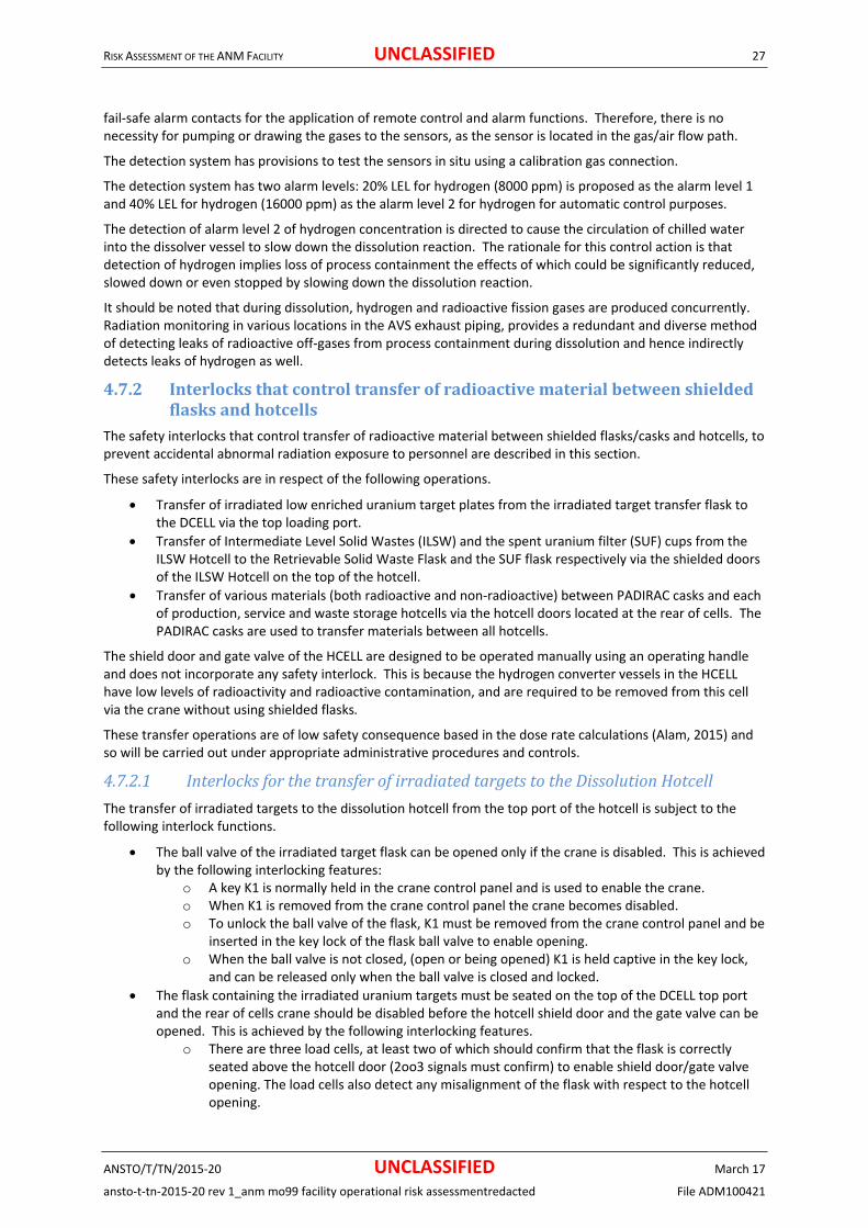
RISK ASSESSMENT OF THE ANM FACILITY UNCLASSIFIED 27
ANSTO/T/TN/2015‐20 UNCLASSIFIED March 17
ansto‐t‐tn‐2015‐20 rev 1_anm mo99 facility operational risk assessmentredacted File ADM100421
fail‐safe alarm contacts for the application of remote control and alarm functions. Therefore, there is no necessity for pumping or drawing the gases to the sensors, as the sensor is located in the gas/air flow path.
The detection system has provisions to test the sensors in situ using a calibration gas connection.
The detection system has two alarm levels: 20% LEL for hydrogen (8000 ppm) is proposed as the alarm level 1 and 40% LEL for hydrogen (16000 ppm) as the alarm level 2 for hydrogen for automatic control purposes.
The detection of alarm level 2 of hydrogen concentration is directed to cause the circulation of chilled water into the dissolver vessel to slow down the dissolution reaction. The rationale for this control action is that detection of hydrogen implies loss of process containment the effects of which could be significantly reduced, slowed down or even stopped by slowing down the dissolution reaction.
It should be noted that during dissolution, hydrogen and radioactive fission gases are produced concurrently. Radiation monitoring in various locations in the AVS exhaust piping, provides a redundant and diverse method of detecting leaks of radioactive off‐gases from process containment during dissolution and hence indirectly detects leaks of hydrogen as well.
4.7.2 Interlocksthatcontroltransferofradioactivematerialbetweenshieldedflasksandhotcells
The safety interlocks that control transfer of radioactive material between shielded flasks/casks and hotcells, to prevent accidental abnormal radiation exposure to personnel are described in this section.
These safety interlocks are in respect of the following operations.
Transfer of irradiated low enriched uranium target plates from the irradiated target transfer flask to the DCELL via the top loading port.
Transfer of Intermediate Level Solid Wastes (ILSW) and the spent uranium filter (SUF) cups from the ILSW Hotcell to the Retrievable Solid Waste Flask and the SUF flask respectively via the shielded doors of the ILSW Hotcell on the top of the hotcell.
Transfer of various materials (both radioactive and non‐radioactive) between PADIRAC casks and each of production, service and waste storage hotcells via the hotcell doors located at the rear of cells. The PADIRAC casks are used to transfer materials between all hotcells.
The shield door and gate valve of the HCELL are designed to be operated manually using an operating handle and does not incorporate any safety interlock. This is because the hydrogen converter vessels in the HCELL have low levels of radioactivity and radioactive contamination, and are required to be removed from this cell via the crane without using shielded flasks.
These transfer operations are of low safety consequence based in the dose rate calculations (Alam, 2015) and so will be carried out under appropriate administrative procedures and controls.
4.7.2.1 InterlocksforthetransferofirradiatedtargetstotheDissolutionHotcell
The transfer of irradiated targets to the dissolution hotcell from the top port of the hotcell is subject to the following interlock functions.
The ball valve of the irradiated target flask can be opened only if the crane is disabled. This is achieved by the following interlocking features:
o A key K1 is normally held in the crane control panel and is used to enable the crane. o When K1 is removed from the crane control panel the crane becomes disabled. o To unlock the ball valve of the flask, K1 must be removed from the crane control panel and be
inserted in the key lock of the flask ball valve to enable opening. o When the ball valve is not closed, (open or being opened) K1 is held captive in the key lock,
and can be released only when the ball valve is closed and locked.
The flask containing the irradiated uranium targets must be seated on the top of the DCELL top port and the rear of cells crane should be disabled before the hotcell shield door and the gate valve can be opened. This is achieved by the following interlocking features.
o There are three load cells, at least two of which should confirm that the flask is correctly seated above the hotcell door (2oo3 signals must confirm) to enable shield door/gate valve opening. The load cells also detect any misalignment of the flask with respect to the hotcell opening.

RISK ASSESSMENT OF THE ANM FACILITY UNCLASSIFIED 28
ANSTO/T/TN/2015‐20 UNCLASSIFIED March 17
ansto‐t‐tn‐2015‐20 rev 1_anm mo99 facility operational risk assessmentredacted File ADM100421
o The HMI will show a fault unless all three load cells provide the same signal. Thus, a single faulty load cell is revealed during operations but will not hinder the door operations.
o The load cells provide only one of the permissive for opening the shield door and the gate valve, but there is another requirement i.e. the disabling of the rear of cell crane using another captive key K2.
o K2 is normally held in the crane control panel when the crane is enabled and is released only when the crane is disabled.
o To enable opening of the shield door and gate valve, K2 must be inserted in the shield door/gate valve control panel of the hotcell.
o When either the shield door or the gate valve is not closed, (open or being opened) K2 is held captive in the door and gate valve control panel and can be released only when the shield door and the ball valve are both closed.
o The shield door of the hotcell has safety rated limit switches to signal both open and closed positions. The limit switches are also backed up by encoder signals relayed to the safety PLC.
o The gate valve open/close status is signalled by encoders and motor torque measurement. o Both captive keys K1 and K2 must be back in the crane control panel to enable crane
operation.
4.7.2.2 InterlocksforthetransferofradioactiveitemsfromtheILSWHotcell
The safety interlocks for the transfer of radioactive items from the ILSW Hotcell are similar to the DCELL described above in section 4.7.2.1. The transfer operations in ILSW Hotcell will involve one of two different flasks.
The SUF flask for the transfer of SUF cups
The retrievable solid waste flask for the transfer of ILSW.
A different roof plug insert (a frame with a round or square opening) is used for the two flasks above. There are four load cells under these inserts. The load cells can discriminate between the presence and absence of the flask on top of the inserts. Three out of four (3oo4) load cells should provide signals to confirm the presence of the flask to permit opening of the hotcell shield door or the gate valve. The load cells detect the presence of the flask but will not detect any misalignment of the flask relative to the hotcell opening because the insert would transfer the weight of the flask to the load cells even if misaligned. The load cells also do not detect whether the correct insert has been used with the flask to be used.
Each of the above flasks has a captive key (K1) which would interface with the ANM facility crane in the same way as for the irradiated target flask in DCELL.
The retrievable solid waste flask has a motorised winch and a grab assembly, which has integral safety interlocking features as described in its design manual (Greenlees, 2014). K1 is held captive in this flask unless all conditions associated with this flask are safe, i.e. grab is fully retracted and its shield door is closed.
The SUF flask has a manual loading mechanism and has no integral interlocking systems, other than the captive key K1 which is held in the key lock unless the flask door is closed.
The captive key K2 in the crane control panel is required to be removed from the crane control panel and inserted in the shield door and gate valve control panel of ILSW Hotcell to enable the opening of the ILSW shield door and the gate valve.
To enable closing of the shield door and gate valve, both keys K1 and K2 must be inserted in the shield door and gate valve control panel. This means that the flask valve must be closed first before the shield door and gate valve of the hotcell. This ensures that the shield door and gate valve cannot close on a waste bin, SUF cups, or the cables /string connecting the waste bin/SUF cups to the flask.
4.7.2.3 MechanicalinterlocksforthetransferofradioactiveitemsusingthePADIRAC/DPTEcasksbetweenhotcells
The transfers of various radioactive items between hotcells are carried out using the proprietary system referred to as PADIRAC/DPTE system. DPTE is a Getinge registered trade mark for “Double Porte pour Transfert Etanche” system (French for, “Double door for Leak‐tight Transfer” system, used for contamination control).
The objectives of the PADIRAC/DPTE system are:

RISK ASSESSMENT OF THE ANM FACILITY UNCLASSIFIED 29
ANSTO/T/TN/2015‐20 UNCLASSIFIED March 17
ansto‐t‐tn‐2015‐20 rev 1_anm mo99 facility operational risk assessmentredacted File ADM100421
1) to maintain shielding and thus prevent inadvertent radiation exposure to personnel during the transfers; and
2) to maintain a depression in the cell containment boxes relative to the external room pressure, thereby maintain confinement and prevention migration of material from the containment boxes to the room environment.
The PADIRAC/DPTE system consists of the PADIRAC cask, DPTE (Beta) Container, PMP (Porte A Masselottes PADIRAC) shield door (of the hotcell), DPTE door of the hotcell, PADIRAC cask shield door, PADIRAC Table Support (PTS) and Alpha Flange (see Figure 5).
The system allows for transfer of materials into and out of shielded and containment enclosures while maintaining containment and providing shielding utilising highly reliable and mostly robust mechanical equipment and manual processes.
The PADIRAC cask is a shielded container used to house the DPTE (Beta) gas tight container. The cask is also equipped with a vertically sliding shield door that is raised or lowered with the PTS using a motorised operating mechanism. The PTS when correctly aligned also engages with the PMP shield door located outside at the hotcell opening for PADIRAC transfers.
The PMP shield door and the PADIRAC cask shielding door are thus raised and lowered together by the PTS operating mechanism to open or close the transfer path between the hotcell and the PADIRAC cask via the DPTE door, the PMP shield door and the PADIRAC cask door. The DPTE door of the hotcell is operated manually from the front of cell using the cell manipulators. When the PMP shield door is raised open two hinged sector shaped blocks of shielding shields drop down and close any gaps in shielding. When the PMP door is closed/lowered these hinged blocks are pushed up by the PMP door sliding down on them.
The normal operating procedure for the use of the PADIRAC system to remove radioactive items from a hotcell involves the following steps:
1. Load the empty PADIRAC cask on to the PTS of the PADIRAC Trolley by crane. The PADIRAC trolley is normally stationed opposite the hotcell door at a distance of about 1m away from the hotcell PMP door.
2. Push the PADIRAC trolley in using a ratchet handle, to engage with the hotcell PMP door. 3. Raise the PTS by holding a push button control ON until the both PADIRAC cask door and the PMP
door open together fully (as they are mechanically coupled via the PTS. 4. Push the DPTE container in the PADIRAC cask using the operating rod to mate with the DPTE door of
the flask, and lock it by turning the operating rod handle and establishing an air seal. The DPTE container has a bin inside, in which the material to be transferred is contained. This bin has a lid.
5. The act of turning the operating handle to lock the DPTE container to the hotcell opening also causes the lid of the bin inside the DPTE container to be removed and to be attached to the outside of the DPTE door of the hotcell.
6. There are three electrical proximity sensors mounted on the DPTE door that signal (i) DPTE bin in position (ii) DPTE lid removed and (iii) DPTE door locked/unlocked status.
7. Open the DPTE door (the inner containment door) of the hotcell from the inside of the cell, using the manipulators. (The hotcell containment function is maintained by the mating of the DPTE container opening with the hotcell inner door opening).
8. Load the radioactive items to be transferred from the hotcell the DPTE container using the hotcell manipulators.
9. Close the DPTE door of the hotcell restoring containment function. 10. Unlock the DPTE container attachment to the hotcell and pull the DPTE container into the PADIRAC
flask using the operating rod. 11. Close the DPTE door from the front of cell using the manipulators. 12. Lower i.e. close both the shield doors (the PADIRAC shield door and the PMP door of the hotcell)
together using the push button controls of the PADIRAC trolley. 13. Retract the PADIRAC trolley with its flask containing the radioactive items and its shield door closed. 14. Move the PADIRAC flask and its contents to its intended destination using the Rear of Cells overhead
crane leaving the PADIRAC trolley in its normal station, which is opposite the hotcell PMP door and about 1m distance away from the hotcell.

RISK ASSESS
ANSTO/T/
ansto‐t‐tn
The proceradioactivthe proce
The PADI
Tco
T
Ts
This wou
4.7.3
4.7.3.1
The B(U) The Mo‐9which is acontaininmanipula
The B(U)
Figure 8 b
The Packashield do
The steps
Step 1:
MENT OF THE ANM
/TN/2015‐20
‐2015‐20 rev 1_
edure for loadve material iness described
RAC/DPTE sys
The PADIRAC can be openeopening of thmechanical inbetween the
The DPTE conhotcell ensurihotcell.
The sensors ostatus of the D
ld then enable
SafetyIn
B(U)Po
Inner Contain99 product is calso containedng the MPB is ators.
port loading s
below.
aging Hotcell or underneat
s involved in p
M FACILITY
_anm mo99 fac
ding radioactivn another hotcabove.
stem ensures
PTS has to beed. This is nore PADIRAC canterlock systemPADIRAC cask
ntainer inside ing a seal agai
on the DPTE dDPTE door.
e the hotcell o
nterlocksf
ortProduct
ner, abbreviatcontained in ad in another cthen then loa
system is illus
Figure
has a Bottomh the B(U) po
posting out a p
UN
UNcility operation
ve items into cell which is th
the following
e engaged witmally done wask door and tm that maintak and the hotc
the PADIRAC inst any releas
oor confirm th
operators to o
fortheB(U
tDespatch
ted as B(U) IC a product concontainer refeaded into the
strated in
e 8‐ Componen
m Port Door (alrt in the conta
package from
NCLASSIFI
NCLASSIFIal risk assessm
a hotcell is simhen transferre
g mechanically
th the shield dwhen the PADIthe hotcell shiains the shieldcell.
cask has to bese of airborne
he presence o
open the DPT
U)Portint
Procedure
is used to desntainer referreerred to as theB(U) IC via the
nts of the B(U
lso referred toainment box.
the Packagin
IED
IEDentredacted
milar, except ed into the re
y implemente
door of the hoRAC cask is seield door is cading function
e pushed agaie contaminati
of bin, the ope
E door from t
thePackag
spatch Mo‐99ed to as the Me Inner Produce B(U) port in
U) IC Loading S
o as B(U) port
g cell are:
that the flask ceiving hotcel
d safety inter
tcell before theated on the Prried out simuduring the tra
inst the DPTE on, to unlock
en status of th
he front of ce
gingHotce
product fromMolybdenum Pct Container (the Packaging
System
t door) in its co
File A
is initially loall using the re
rlocking functi
he hotcell shiePADIRAC PTS. ultaneously. Tansfer of item
door openingthe DPTE doo
he lid and the
ell using manip
ell
m the packaginProduct BottleIPC). The IPC g Hotcell usin
ontainment b
30
March 17
ADM100421
aded with everse of
ions:
eld door The This is a s
g of the or of the
unlocked
pulators.
ng cell. e (MPB)
g the cell
box and a

RISK ASSESS
ANSTO/T/
ansto‐t‐tn
The emptB(U) portTrolley Ca
Step 2:
The shieldlocated athe radiatdeterminpossible r
Step 3:
The platfoB(U) IC is contact wsudden inhandle, wflange, th
Step 4:
The procesensor cothe trolle
Step 5:
A sensor in its closplatform level belo
Step 6:
The B(U) removed loading sy
MENT OF THE ANM
/TN/2015‐20
‐2015‐20 rev 1_
ty B(U) IC is pt from the fronart Present se
d door has to nd aligned untion level insined during hotradiation over
orm of the tro positioned unwith the contancrease in thewhich pulls thehereby making
ess of engaginonfirms that they table is bot
in the B(U) posed position. Aunless conditow a safe limit
port door is ousing a magnystem with B(
M FACILITY
_anm mo99 fac
laced on the pnt of the packensor.
be opened finderneath thede the packagt commissionir exposure to
olley cart can nderneath theainment box de resistance ofe B(U) IC up ag a seal.
ng the draw lahe table is both up and lock
ort door detecA solenoid loctions are rightt.
opened after tnet operated l(U) port door
Figure 9 – B(U
UN
UNcility operation
platform of a tkaging cell. Th
rst to allow the B(U) port of ging cell is aboing, and is exppersonnel du
be raised usine B(U) port is docking flangef the foot pednd compresse
atch brings theth up and locked.
cts the presenck gets activatt for safe lowe
the B(U) IC is difting device iopen.
U) IC Loading
NCLASSIFI
NCLASSIFIal risk assessm
trolley cart anhe correct pos
he trolley to bthe cell. Safeove a safe threpected to be buring the trans
ng a foot‐operraised using te. The operatodal. The operaes the O‐ring b
e “up‐and‐locked (thus the
nce or the absted when the ering i.e. B(U)
docked underinside the pac
g System show
IED
IEDentredacted
nd then wheesitioning of th
e fully inserteety interlocks peshold limit. between 0.1 tsfer process.
rated hydraulthe hydraulic for will sense tator will then between the
cked” sensor iname). The B
sence of the Bdraw latch is port door clo
r the B(U) porckaging cell. F
wn with the B(
led in on guide trolley cart
ed into positioprevent the shThis radiationo 1mSv/h. Th
ic pump. Thefoot pump unthat the contaengage a drawB(U) IC and th
nto the sensinB(U) port door
(U) IC lid whemade and presed, IC lid pre
t. This enableFigure 9 below
(U) door open
File A
de rails undernis confirmed
on, so that thehield door opn level setting his interlock p
e platform witntil the B(U) ICact has been mw latch using he containmen
ng range. Thur can be open
en the B(U) poevents loweriesent and radi
es the B(U) IC w shows the B
n
31
March 17
ADM100421
neath the by the
e B(U) IC is ening if is to be
prevents
h the C makes made by a a crank nt box
us this ned only if
ort door is ng of the iation
lid to be B(U) IC

RISK ASSESS
ANSTO/T/
ansto‐t‐tn
Step 7:
Once theinto the Bis closed.is not detcannot be
Step 8:
The releainterlock
Td
T
Once theswitch), t
In additiomonitors
4.7.3.2
The oper
T
There areThese dothat only these cel
Figure 1
MENT OF THE ANM
/TN/2015‐20
‐2015‐20 rev 1_
B(U) port dooB(U) IC using t When the B(tected when te lowered.
ase of the soleconditions:
The radiation during hot co
The B(U) port
trolley platfothe B(U) trolle
on to the step radiation lev
Detailsational contro
“Trolley cart p
“Trolley cart u
“Shield door o
“Shield door c
“Bottom port
“Bottom door
“IC Lid Presen
Radiation Mo
Trolley cart lo
e two pneumaors do not proone pass‐throls.
0‐ The genera
M FACILITY
_anm mo99 fac
or is opened athe hotcell ma(U) port door the B(U) port
enoid lock pre
level inside tmmissioning a
t door must be
orm and the Bey can be draw
s noted aboveels, to provide
sofB(U)Pool and safety i
present” sens
up and locked
open” sensor
closed” senso
door open” s
r closed” sens
nt” sensor
onitor‐ Canber
ocking solenoi
atically operatovide any shieough door is o
al arrangemetroll
UN
UNcility operation
and the B(U) Ianipulators, afis closed the door is closed
venting the lo
he packaging and expected
e closed and t
(U) IC containwn out.
e, a radiation e warning to t
ortInterlocknterlocks util
or (safety rate
d” sensor (safe
(safety rated
r (safety rated
sensor
sor
rra G64
d
ted pass‐throuelding, but preopened at a ti
nt of pass‐thrley, shield doo
NCLASSIFI
NCLASSIFIal risk assessm
C lid removedfter which thlid sensor cond, the solenoid
owering of the
cell should bed to be in the r
the lid presen
ner has been f
monitor withthe operator o
kFeaturesise the follow
ed inductive c
ety rated indu
limit switch)
d limit switch)
ugh doors betevent cross coime when ma
rough doors bor of packagin
IED
IEDentredacted
d, it is possiblee B(U) IC lid isnfirms that thed lock cannot
e platform is s
e below a saferange 0.1‐1mS
t sensor shou
fully lowered (
its probe locaof any above
wing sensors, li
coupled proxim
uctive coupled
)
tween the disontamination terials and ot
between dispeng cell and B(
e for operators closed and te lid is presenbe released a
subject to the
e threshold vaSv/h).
ld confirm the
(by releasing a
ated undernenormal radiat
imit switches
mity sensor)
d proximity se
pensing cell abetween the her items are
ensing cell an(U) IC
File A
rs to load the hen the B(U) nt. If the lid’s and the platfo
e following saf
alue (to be det
e presence of
a hydraulic va
ath the B(U) ption levels.
and actuating
nsor)
and the packagtwo cells by e to be passed
nd packaging
32
March 17
ADM100421
IPC/MPB port door presence rm
fety
termined
f the lid.
alve
port also
g devices.
ging cell. ensuring between
cell, B(U)

RISK ASSESS
ANSTO/T/
ansto‐t‐tn
The pneushows th
Opening door is opthat a radshield doport.
Figure 11using a shsystem is
In summa
Table 3 S
Condition
The radiatpackaging in cell radithan the s(in the randecided ducommissio
Shield doois open AN
The trolleyfully or thecorrectly.
The lid of tpresent (apresence s
MENT OF THE ANM
/TN/2015‐20
‐2015‐20 rev 1_
umatic systeme general arra
of the pass‐thpen, unless thdioactive souror of the pack
1 shows a schehut off valve ws such that on
Figure 11 –
ary, the safety
Safety Interloc
s
tion level inside cell measured iation monitor afe threshold snge 0.1‐1mSv/huring hot oning.
or under the B(UND
y table is not rae IC is not dock
the B(U) IC is nos detected by tsensor).
M FACILITY
_anm mo99 fac
m is such that oangement of t
hrough doors he B(U) IC trolrce could be pkaging cell is o
ematic diagrawhich blocks dly one of the p
– Schematic d
y interlock fun
ck functions fo
Inte
e the by the is higher setting h) to be
Thepor
Thelow
U) port
aised ked
Paspaccell
ot the lid
Trolowcan
UN
UNcility operation
only one of ththe pass‐throu
is also interloley is docked passed througopen and the
m of the pneudoor operatiopass‐through
diagram of the
nctions associ
or the B(U) Po
erlocking Funct
e Shield door unrt cannot be op
e B(U) IC trolleywered.
ss‐through doorckaging cell andl cannot be ope
olley platform cwered as the sonnot be release
NCLASSIFI
NCLASSIFIal risk assessm
he pass‐througugh doors bet
ocked to preveagainst the Bh to the packaB(U) trolley a
umatic operatons when conddoors can be
e pneumatic c
ated with B(U
ort of the Pac
tion
nder the B(U) pened.
y cart cannot be
rs between thed the dispensingened.
annot be lenoid lock d.
IED
IEDentredacted
gh doors can btween the Dis
ent their open(U) port openaging cell fromnd B(U) IC con
ting system. Tditions are noopened at an
control system
U) Port of the
ckaging Cell
Remarks
Prevents hbe exposedinsert the tis present
e Prevents tsource couopen and tabnormal
e g
Prevents tsource coucell when ttrolley IC isa radiationprevents tdropped than IC in pla
Prevents twith a highwithout th
be opened at pensing Cell a
ning when theing. This prevm the dispensntainer is not
The interlockint correct. Theny one time.
m for pass‐thr
packaging cel
high radiation led to when the strolley cart within the packagin
he possibility thuld be present wthe B(U) IC is loradiation expos
he possibility thuld be passed ththe shield doors not docked, wn shine path to the possibility thhrough the B(Uace.
he possibility thh activity sourcee IC lid closed.
File A
any time. Figand Packaging
e packaging cevents the posssing cell whendocked with
ng function ise pneumatic c
rough doors
l are tabulate
evel the operatshield door is oh B(U) IC, if higng cell.
hat a high radiowhen the shieldowered. Hencesure to personn
hat a high activhrough to the pr is open, and thwhich would thethe outside. Ahat a source coU) port opening
hat the B(U) IC e could be lowe
33
March 17
ADM100421
ure 10 g cell.
ell shield sibility the the B(U)
achieved control
ed below.
or could opened to h activity
oactivity d door is prevent nel.
vity packaging he B(U) en allow lso uld be without
loaded ered

RISK ASSESSMENT OF THE ANM FACILITY UNCLASSIFIED 34
ANSTO/T/TN/2015‐20 UNCLASSIFIED March 17
ansto‐t‐tn‐2015‐20 rev 1_anm mo99 facility operational risk assessmentredacted File ADM100421
4.7.4 ControlandinterlockingfunctionsoftheAVSrelatedtoProcessContainment
The control of the vacuum pumps and valves for the various process transfers of Process Containment are effected by a Programmable Logic Controller (PLC) system with appropriate process controls and interlocking. This control system is part of the overall Process Control System (PCS) for ANM Mo99 Production Process. Operator control is implemented via a Human Machine Interface (HMI).
The control and interlocking functions of the AVS related to Process Containment are listed below.
The AVS controls carries out the sequential selection of the gas decay tanks for both dissolver off‐gas and filtration off‐gas for a given dissolution run. Two gas decay tanks are selected for each batch run to be evacuated and be made ready to receive off‐gas from the dissolver. In addition, a gas decay tank from the bank of gas tanks for filtration off‐gas is selected, evacuated and made ready for filtration off‐gas.
Of the two gas decay tanks selected for a batch run, only one is connected to the process containment system by the gas decay tank valves. The other evacuated gas tank is on standby.
During the dissolution run if the gas tank pressure reaches 100kPa (a) the AVS controls system disconnects the connected gas tank and connects the second gas decay tank which is still held evacuated.
The evacuation of gas decay tanks involves the closing of the inlet valves and opening of the outlet valves of the selected gas tanks and operating the vacuum pumps. All tank gases are discharged through the carbon columns.
In addition to the two gas decay tanks for the dissolver off‐gas and the selected gas decay tank for the filtration off‐gas, a dedicated gas tank is evacuated and kept ready each for each dissolution run, to receive gases from the dissolver in the case of over‐pressurisation and the rupture of the bursting disc of the process containment i.e. associated with the selected dissolver vessel.
4.7.5 ControlandinterlocksandalarmsoftheProcessControlSystemIn addition to the AVS controls and interlocks pertaining to process control as described above, the following main control and interlocking and alarm features are implemented in a separate and independent PLC control system as detailed in the Functional Specification of the Process Control System (Mehl, 2015).
The PCS keeps track of the usage of the hydrogen converters in the conversion (i.e. during dissolution) and regeneration modes. The control system permits the commencement of a dissolution run only if the selected hydrogen converter for dissolution has had adequate regeneration prior to its use in the dissolution process.
Each hydrogen converter has enough capacity to convert the hydrogen produced from three separate dissolutions. To allow for a margin of safety, however, the PCS only allows two conversions before regeneration of a hydrogen converter.
The PCS ensures that the pneumatic control valve V001 of the hydrogen converter selected for a dissolution run is in the Open state and the pneumatic control valve V003 is kept closed. (This valve (V003) is used in the Open position in the Regeneration mode only and kept closed otherwise).
The PCS ensures that a dissolution process cannot commence unless the dissolver vessel, the gas management vessel, the selected hydrogen converter, are subjected to both pressure tests and vacuum tests for leakage. In addition , the part of process containment after the hydrogen converter outlet valve, i.e. the selected off‐gas decay tanks and the dedicated gas decay tank for pressure relief are all subjected to a vacuum test.
All these tests and checks are also subjected to batch run check list by two operators (double sign off).
The hydrogen converter temperature is controlled by the use of duplicate thermocouples in each band heater. One thermocouple in each band heater is used for control and the second thermocouple is used for over temperature safety cut off.

RISK ASSESSMENT OF THE ANM FACILITY UNCLASSIFIED 35
ANSTO/T/TN/2015‐20 UNCLASSIFIED March 17
ansto‐t‐tn‐2015‐20 rev 1_anm mo99 facility operational risk assessmentredacted File ADM100421
The PCS ensure that the dissolution process cannot commence unless the hydrogen converter temperature has reached a minimum. This ensures that hydrogen conversion is reliable during dissolution.
The temperatures and pressures in various process tanks and vessels are monitored. The measurements are recorded in the batch sheets and are also automatically recorded in the history log of the PCS and AVS control systems.
Under certain fault conditions listed below the PCS generates a signal to cause chilled water to be circulated in the dissolver jacket to reduce the dissolution reaction rate. This enables operators sufficient time to take appropriate action to address the issue of pressurisation or hydrogen leak and take suitable remedial steps.
Over pressure detected in the dissolver
Hydrogen concentration above 10% LEL detected in the Red primary exhaust duct of AVS.
4.8 RadiationandcontaminationmonitoringandalarmsThe I&C Functional Requirements Specification (ANM Mo99 Project, 2013) and the I&C design manual (AECOM 2014) provides the detailed specifications of the radiation monitoring systems. Described below are the main functional and technical specifications of the RMS.
There are seven aspects of the RMS relevant to the radiological safety of personnel.
1. Radiation Air Sampler Monitoring System (RASM) detecting airborne radioactive contamination in selected locations in the facility
2. Alpha / Beta counters (Beta castle) in selected locations in the facility
3. Local area radiation monitors to indicate the radiation levels in selected locations in the facility
4. Radiation monitors used for safety interlocking or for alarms preventing accidental radiation exposure to personnel
5. Process radiation monitors that directly and continuously monitor the radiation/contamination levels associated with the production and waste management processes, including the active ventilation system
6. Radiation monitors associated with stack discharge monitoring
7. Contamination monitors used for personnel monitoring e.g. hand and foot contamination monitors and walk though monitors
The above subsystems are further described in ANSTO/T/TN/2015‐05.
The current locations of these area monitors and associated detectors in the basement, the mezzanine floor and the ground floor areas are shown below. Final placement will be confirmed by the RPA during hot commissioning.

RISK ASSESSMENT OF THE ANM FACILITY UNCLASSIFIED 36
ANSTO/T/TN/2015‐20 UNCLASSIFIED March 17
ansto‐t‐tn‐2015‐20 rev 1_anm mo99 facility operational risk assessmentredacted File ADM100421
Figure 12‐ Layout of Radiation Monitoring in the Ground Floor

RISK ASSESSMENT OF THE ANM FACILITY UNCLASSIFIED 37
ANSTO/T/TN/2015‐20 UNCLASSIFIED March 17
ansto‐t‐tn‐2015‐20 rev 1_anm mo99 facility operational risk assessmentredacted File ADM100421
Figure 13‐ Layout of Radiation Monitoring in the Mezzanine Floor

RISK ASSESSMENT OF THE ANM FACILITY UNCLASSIFIED 38
ANSTO/T/TN/2015‐20 UNCLASSIFIED March 17
ansto‐t‐tn‐2015‐20 rev 1_anm mo99 facility operational risk assessmentredacted File ADM100421
Figure 14‐ Layout of Radiation Monitoring in the Basement

RISK ASSESSMENT OF THE ANM FACILITY UNCLASSIFIED 39
ANSTO/T/TN/2015‐20 UNCLASSIFIED March 17
ansto‐t‐tn‐2015‐20 rev 1_anm mo99 facility operational risk assessmentredacted File ADM100421
4.8.1 RadiationMonitorsusedforSafetyInterlockingand/orAlarmsRadiation monitors were considered for safety interlocking and/or alarms in certain selected locations, for implementing the required safety instrumented functions (SIF), to protect personnel against possible accidental radiation exposure.
The determination of the Safety Integrity Levels (SIL ratings) and the functional requirements of the SIF are documented in a SSR Calculation and Data Sheet (Jani, 2015). This document will also form the basis of a future regulatory submission on interlocking. It has been determined on the basis of these analyses that the radiation monitors are only required to provide indication of the radiation levels with some warning of unsafe radiation levels, but are not required to interlock any operations, to meet an acceptable level of risk.
Details of the radiation monitors used for such purpose are tabulated below.
The Table shows each potential hazardous scenario with significant radiological consequence, and the details of radiation monitors to be provided for interlocking or alarming designed to prevent such accidents.
.

RISK ASSESSMENT OF THE ANM FACILITY UNCLASSIFIED 40
ANSTO/T/TN/2015‐20 UNCLASSIFIED March 17
ansto‐t‐tn‐2015‐20 rev 1_anm mo99 facility operational risk assessmentredacted File ADM100421
Table 4 Radiation Monitors for Alarms preventing accidental radiation exposure.
Potential hazardous scenario with accidental radiation
exposure
Location of Radiation Detector
Location of Radiation Monitor
Type/Model of Radiation
Detector and Monitor
Maximum expected radiation level to which personnel could be exposed.
Range of measurement
Proposed alarm setting
Remarks
Operator removes B(U) IC flask with external dose rate > 2mSv/h.
Below the Packaging cell on the B(U) trolley compartment
On the side of packaging cell
Canberra G64 or Lab Impex CMS interlock monitor
4 mSv/h 0.1 µSv/h ‐100mSv/h
2mSv/h An alarm/indication if the radiation level is above the maximum allowable radiation level (2mSv/h)
Operator or maintenance worker opens the maintenance access door of the liquid waste sampling hotcell when there is high activity inside.
Inside the liquid waste sampling cell
In the cell face of liquid waste sampling cell
Canberra G64 or Lab Impex CMS interlock monitor
10‐30mSv/h 0.1 µSv/h ‐100mSv/h
100µSv/h An alarm/indication showing the radiation level inside the cell. .
Operator enters liquid waste valve room without adequate flushing of residual waste in the pipes.
Inside the liquid waste valve room
Outside the liquid waste valve room access door
Ludlum Area Monitor
10‐30mSv/h 0.1 µSv/h ‐100mSv/h
100µSv/h An alarm/indication showing the radiation level inside the valve room
Operator opens the maintenance access door of the packaging cell without first ensuring that there is no significant radioactivity inside the cell.
Inside the packaging cell in a suitable location.
On the rear of cells close to the rear maintenance access door.
Canberra G64 or Lab Impex CMS interlock monitor
3Sv/h <10 000mSv/h 200µSv/h An alarm/indication showing the presence of significant radioactivity inside the cell. High radiation field.
This radiation detector could be the same as the one to be used for interlocking against accidental opening of B(U) port door with radioactivity inside the cell.

RISK ASSESSMENT OF THE ANM FACILITY UNCLASSIFIED 41
ANSTO/T/TN/2015‐20 UNCLASSIFIED March 17
ansto‐t‐tn‐2015‐20 rev 1_anm mo99 facility operational risk assessmentredacted File ADM100421
5. SUMMARYOFOPERATIONSA detailed operating procedure, called a batch sheet, will be the basis for operating the process. This will be prepared based on Mo‐99 operating experience at B54 and input from the design collaborators NTP. It will be revised as needed following the experience gained during hot commissioning. This batch sheet procedure will be supported by a set of work instructions. Production technicians will be trained extensively before they are authorised to operate the plant supported by Senior Technicians, one of whom must be present at all times and authorised to operate the plant.
The plant will be operated in a batch mode. Each batch run will consist of a dissolution step followed by filtering and subsequent steps to extract and purify the Mo‐99. An overview of the main operations and staff activities is given below.
5.1 OperationsoutsidethefacilitybuildingThere will be some operations necessary for the functioning of the ANM Mo99 facility that take place outside the building.
The main activities involve the transfer of active solids and liquids. ANM Mo99 operations will transfer the irradiated targets in the target transfer flask from the OPAL reactor to the ANM Mo99 building. Waste operations staff will take active solid wastes from the ILSW cell by truck from the building in the retrievable waste flask and SUF cups in the SUF flask. These operations for the proposed ANM Mo99 facility will be similar to the existing operations for which there are approved procedures under the Waste Operations ARPANS licence F0260. Active liquid wastes (ILLW) will be removed from the facility by pipeline to the Synroc facility and by Waste Operations in a flask. LLLW will be transferred via a flask and trucked to waste operations for subsequent drum drying.
Product Mo‐99 will be despatched from the building. This is an existing operation within ANSTO. The procedures for transport of the product in approved containers are approved for international travel and are not discussed in this report.
There will be deliveries of materials and chemicals to the building and removal of materials including low activity solid wastes. These types of operations are well established on the ANSTO site. They do not present significant radiation or other hazards and are not discussed further in this report.
5.2 TransportofTargetsfromB80toANMThe transport of targets from OPAL to the ANM Facility is conducted according to Work Instruction ARI/ 09 07 02 0 D.wk1 (Jones et al, 2007).
The targets are removed from the OPAL Service Pool (SPO) and transferred to the Transfer Hotcell (THC). The Service Pool Elevator (SPE) that raises the Bulk Irradiation Rig (BIR)containing irradiated targets from the SPO into the THC has a radiation‐based interlock called the Molybdenum Safety Device (MSD). If the radiation detected from the targets exceeds a predetermined value on one of two radiation detectors, then the SPE stops.
Once removed from the SPO the BIR is disassembled and the targets are removed. The targets are then loaded into target transport holders. The holders are sent to the Loading Hotcell (LHC), where they are then loaded into a carrier which is then loaded into the 7.5 tonne transport flask. The carrier and the flask rotating door are then secured prior to transport.
The flask is then loaded onto a truck for transport to the ANM Mo99 Facility. During transport, the flask is secured to the truck using 4 mild steel chain “tie‐downs”. The flask is classified as being a hazardous load, and as such during transport there is an on‐site speed limit of 10 km/h (Jones et al, 2007).
On arrival at the ANM Mo99 Facility truck bay, the flask is lifted off the truck onto the cell roof, where it is placed over the Dissolver Cell, using the building crane. The targets are then lowered into the cell for processing.
The flask opening mechanism is an internal ball valve, which is controlled using an indexing lever that moves through an angle of 90 degrees. The indexing lever is secured in either the open or closed position by screwing its handle into the threaded hole of one of the two stop blocks mounted on the surface of the front shield plug. The words ‘DOOR OPEN’ and ‘DOOR CLOSED’ are clearly engraved on the front surface of the shield plug.

RISK ASSESSMENT OF THE ANM FACILITY UNCLASSIFIED 42
ANSTO/T/TN/2015‐20 UNCLASSIFIED March 17
ansto‐t‐tn‐2015‐20 rev 1_anm mo99 facility operational risk assessmentredacted File ADM100421
A Kirk Key interlock has been installed on the flask as part of a flask‐to‐crane interlock system. This interlock system ensures that the flask cannot be lifted by the overhead crane (in the ANM Facility or OPAL level 4) if the flask’s internal ball valve is open. The lock body is mounted on the front face of the shield plug, while the latch block is mounted on a bracket welded to the flask indexing lever. The two lock components are engaged only when the flask’s internal ball valve is fully closed. It is only when the two lock components are fully engaged that the key can be removed from the lock.
5.3 OperationsintherearofcellsareaThe rear of cells area will be the centre of operations for the movement of the solid active materials into and out of the facility. The hotcells are on the eastern side of this rear of cells area and this area includes the top of the hotcells.
An operator will use the rear of cells crane to lift the target flask from the back of the truck through a hatch into the rear of cells area and into position on the top of the dissolution hotcell. The flask will be docked to the top port, the shielding and containment opened and the targets will be lowered into the hotcell. During this time there will be another operator at the front of the dissolution cell using the manipulators.
Active materials will be removed from and placed into the hotcells by a proprietary shielded cask called a PADIRAC. The PADIRAC will be lifted with the rear of cells crane by an operator into position adjacent to the rear of cell door. The PADIRAC will then be docked and the containment doors opened. A front of cells operator will be using the in‐cell manipulators to remove or bring in materials.
Active solid wastes will be moved out of the hotcells in the retrievable waste flask and the SUF cups will be removed in the SUF flask. An operator will use the rear of cells crane to lift the flask from the back of the truck through a hatch into the rear of cells area and into position on the top of waste hotcell. The flask will be docked to the top port, the shielding and containment opened. The materials will be removed from the waste cell with the help of an operator using the manipulators and the flask will be placed back on the truck.
5.4 OperationsinothergroundfloorareasAfter removal from the hotcell, the Mo‐99 product BU Package Inner Container will be externally tested for radioactive contamination followed by helium leak testing prior to being will be wheeled into the despatch area where it will be finish assembled and undergo Transport Index measurement prior to release for despatch.
There will also be some QC activities in the ground floor area. There will be maintenance checks and work including replacement of manipulators from the front of cell when this is required.
5.5 OperationsinthebasementThis area will house the decay tanks, carbon columns and the primary active filter room which form part of the active ventilation system. It will also house the liquid waste holding tanks and equipment. There will be minimal need to enter the basement except when maintenance is required. The basement area is a prohibited area due to the radiation levels in the basement much higher (1‐10mSv/h) than other areas (such as the ground and mezzanine floor)under normal operating conditions,. Access is allowed only after a 3 day delay following a process shutdown and after careful preparations, including radiation and airborne contamination checks.
5.6 ActiveliquidwastesystemThe ANM Mo99 process generates two active liquid waste streams: Intermediate Level Liquid Waste (ILLW) and Low Level Liquid Waste (LLLW).
ILLW is produced from the filtrate of the dissolved targets after removal of the Mo‐99. This liquid is transferred from the hotcell to a dedicated ILLW temporary holding tank. The liquid will be decayed for at least two weeks in the holding tank, and then transferred to the ILLW decay tanks at the north end of the building. It is allowed to decay for a minimum of two years before it is transferred, using vacuum, to the SyMo Waste Treatment plant.
LLLW is produced during the purification of the Mo‐99 product. The LLLW is transferred from the hotcell to a dedicated LLLW temporary holding tank. The liquid will be decayed for at least two weeks in the holding tank, and then the LLLW is transferred to the LLLW decay tanks at the north end of the building. It is allowed to decay before it is transferred, using the Liquid Waste Flask, to ANSTO Waste Operations for treatment.

RISK ASSESSMENT OF THE ANM FACILITY UNCLASSIFIED 43
ANSTO/T/TN/2015‐20 UNCLASSIFIED March 17
ansto‐t‐tn‐2015‐20 rev 1_anm mo99 facility operational risk assessmentredacted File ADM100421
Other active liquid wastes produced in the ANM Mo99 facility have much less activity and will be managed through the ANSTO “B” Line drainage system. These are not safety category 1 or 2 and are therefore not considered within this report.
An active liquid waste sampling and valve room at the northern end of the ground floor houses the manifolds and valves to direct active liquid waste flows to and from the liquid waste decay tanks.
The valves for the active liquid waste system are contained within a shielded valve room enclosure and the valves will be operated using extended valve stems through the shielding roof of this enclosure. The enclosure will be a restricted area. Access for maintenance will be possible via a shield door under closely controlled conditions.
There is a hotcell for sampling the ILLW and LLLW provided in the valve room. Sampling is required to measure uranium content in the liquid waste, monitor the storage condition and monitoring the facility’s activity balance using gamma spectrometry. It will be adjacent to the liquid waste decay tanks and it will operate at negative pressure relative to the surrounding areas.
The transfer lines from the holding tanks to the decay tanks pass through this sampling room. The ILLW line to the SyMo facility and the LLLW line for filling the LLLW flask originate from this room.
5.7 MezzaninelevelplantroomsThe mezzanine level will have plant rooms for general building services and equipment including the instrumentation and control system, the uninterruptible power supplies and a dedicated plant room for the process Dissolution and Hydrogen Conversion hotcells heating and cooling water hydraulic systems. Maintenance personnel will need to enter these areas.
6. SUMMARYOFPROCESS
6.1 Mo‐99ProcessThe ANM Mo99 facility will produce molybdenum‐99 from the fission of low enriched uranium (LEU). This process is largely based upon proven technolofy.
The process will start by dissolving the targets. The reaction is exothermic and radioactive off‐gases, consisting mainly of krypton and xenon, will be collected in dedicated tanks and held for a sufficient decay period prior to release to the facility red primary ventilation system.
Radionuclides, namely molybdenum and iodine, will be separated from the uranium and insoluble elements by filtration. The molybdenum and iodine isotopes will be separated from radionuclides of other elements.
The off‐gas generated in the dissolution process is directed through a hydrogen converter to convert gaseous hydrogen to water vapour and then through a condenser to remove the water vapour thus controlling the pressure in the process and off‐gas system.
The process will start in the dissolution hotcell where the irradiated targets will be dissolved releasing the fission products into the dissolver vessel. The active gases will pass through a hydrogen converter, and a condenser and the residual gases will be stored in gas decay tanks in the basement. Solid fission products and residual uranium (as a solid oxide) will be retained in a filter and stored in‐cell for decay.
The required Mo‐99 product will be isolated in the train of hotcells. Active liquid wastes will drain to holding tanks in the basement from where they will be transferred to the active liquid waste decay tanks at the northern end of the building.
The activity of the Mo‐99 product will be checked to conform to requirements prior to removal from the hotcells. The Mo‐99 product will then be removed from under the packaging hotcell into a shielded container on a trolley in the front of cells area.
Other hotcells which are not part of the production train include the active solid waste hotcells, the liquid waste sampling hotcell, and the in‐process sampling hotcell.
The figures in Appendix E shows the piping and instrumentation diagrams (P&ID) of the dissolution and hydrogen conversion functions.
Appendix ‐ Piping and Instrumentation Diagram (P&ID) – Dissolution Cell Ref: Mo99_DISS_XXXX_PID_0413_P4

RISK ASSESSMENT OF THE ANM FACILITY UNCLASSIFIED 44
ANSTO/T/TN/2015‐20 UNCLASSIFIED March 17
ansto‐t‐tn‐2015‐20 rev 1_anm mo99 facility operational risk assessmentredacted File ADM100421
Appendix ‐ Piping and Instrumentation Diagram (P&ID) – Hydrogen Conversion Cell Ref: Mo99_HCEL_XXXX_PID_0414_P3
Prior to starting a production run, the following will be performed.
The pre‐start checks will be performed.
The cell services, such as lights, in‐cell power and alarm consoles, will be turned on, if not already on.
All in‐cell valves will be confirmed to be configured correctly.
All operating parameters will be checked and logged on the batch sheet.
The Uranium Management Descriptive Report [ER‐147921, Jones 2015 ] identifies the path, geometry, and inventory of Uranium as it is processed throughout the ANM Mo99 facility.
6.2 HotcelloperationsThe main process operations will take place in the sealed hotcells. All necessary materials will be put into the cells either through the rear of cell doors using the PADIRAC except for the targets which are through the top port. All of the cell operations will be carried out by operators at the front of cell using the manipulators or using the other equipment at the front of cells.
The process will start in the dissolution hotcell where the irradiated targets will be dissolved releasing the fission products into the dissolver vessel. The active gases will be withdrawn through a hydrogen converter and the residual gases will be stored in gas decay tanks in the basement. Solid fission products and residual uranium (as a solid oxide) will be retained in a filter and stored in‐cell for decay.
The required Mo‐99 product will be isolated using ion exchange steps in the train of hotcells. Active liquid wastes will drain to holding tanks in the basement from where they will be transferred to the active liquid waste decay tanks at the northern end of the building.
The activity of the Mo‐99 product will be checked to conform to requirements prior to removal from the hotcells. The Mo‐99 product will then be removed from under the packaging hotcell into a shielded container on a trolley in the front of cells area.
There will be other hotcells which are not part of the production train. The main ones are the active solid waste hotcells which receive wastes including the SUF cups from the production hotcells via the PADIRAC cask.
An overview of the actual hotcell operations is given below.
6.2.1 ProductionHotcellStagesAs described earlier, the layout has been designed with two production lines each consisting of five sealed hotcells either side of a single hotcell for the conversion of hydrogen to water. This layout is shown in Appendix Error! Reference source not found..
All production hotcells will have a removable roof plug and will be designed to allow for future replacement of the inner containment box. The cells will all have low internal pressures relative to atmosphere and will cascade from the lowest pressure in the most active cell to the highest pressure in the least active cell.
The following description gives a summary of the process and requirements for each of these hotcells.
6.2.1.1 DissolutionHotcell
Equipment
The Dissolution Hotcell will house two dissolvers (See Section 4.4.1) and the first separation ion exchange columns. This hotcell will operate at the lowest negative pressure relative to all the Mo‐99 production cells and require the most radiation shielding. See Section 4.2.1 for common hotcell features.

RISK ASSESSMENT OF THE ANM FACILITY UNCLASSIFIED 45
ANSTO/T/TN/2015‐20 UNCLASSIFIED March 17
ansto‐t‐tn‐2015‐20 rev 1_anm mo99 facility operational risk assessmentredacted File ADM100421
Figure 15‐ The Dissolver Figure 16‐ The Dissolution Hotcell and Carbon Columns at the Basement
Figure 17‐ Inside the Dissolution Hotcell
6.2.1.2 HydrogenConversionHotcell
Equipment
The principal equipment in this hotcell will be the hydrogen converter (See Section 4.4.5) and water condenser (see Section 4.4.6) which forms part of the dissolution off‐gases management and containment system. The hotcell will be of a gas tight design and will operate under negative pressure to contain any airborne radioactivity.
RISK ASSESSMENT OF THE ANM FACILITY UNCLASSIFIED 46
ANSTO/T/TN/2015‐20 UNCLASSIFIED March 17
ansto‐t‐tn‐2015‐20 rev 1_anm mo99 facility operational risk assessmentredacted File ADM100421
Figure 18‐ Hydrogen Conversion Process
6.2.1.3 PurificationHotcell
Equipment
This hotcell houses two purification resin columns. In‐cell peristaltic pumps that are used for pumping reagent solutions will be controlled from the operations area.
All process reagents and consumables will be introduced to the sealed hotcell via the rear of the cell using the PADIRAC transfer system.
6.2.1.4 EvaporationHotcell
Equipment
This hotcell will house the evaporation equipment which forms part of the Mo‐99 Solution final conditioning. The hotcell will operate at a higher pressure than the adjacent Purification Hotcell.
The in‐cell peristaltic pumps and evaporation system will be controlled from the operations area.
6.2.1.5 DispensingHotcell
Equipment
This hotcell will house the Mo‐99 solution activity measurement system and the dispensing and weight measurement system. The hotcell will operate at negative pressure with respect to the operations (Blue) area and at a higher pressure than the adjacent Evaporation Hotcell.
The in‐cell activity measurement, dispensing and weight measurement systems will be controlled from the operations area.
6.2.1.6 PackagingHotcell
Equipment
This hotcell will house the packaging equipment for loading the assembled product into the depleted uranium shielded transport container (IC). It will operate at negative pressure with respect to the operations area.
6.2.2 SupportServicesHotcellsThere will be up to six support services hotcells as shown in Appendix Error! Reference source not found.. These are shown with four of the service cells grouped together and positioned to the side of the production cells. The layout in the figure (Appendix Error! Reference source not found.) shows schematically the arrangement of the four group service cells. The fifth service cell (Product Bottle and IPC Storage and Decay) is not shown. It will be located in B23 IHB area. However, space has been provided in the ANM facility for the future location of this hotcell if required. The sixth service cell (Liquid Waste Sampling Hotcell) is also not shown and will be located in the waste tank valve room.
The hotcells will operate at negative pressure and will be provided with an appropriate level of radiation shielding to ensure compliance with ANSTO radiation dose specifications.
These cells will provide the following services as a supporting function to the Molybdenum production processes.
6.2.2.1 IntermediateLevelSolidWaste(ILSW)HandlingHotcell
The Intermediate Level Waste Handling Hotcell will have the function of providing storage, handling and transfer of longer‐lived solid wastes generated during the dissolution process. Wastes generated in the Dissolver Hotcell will be transferred via the PADIRAC system to the Intermediate Level Waste Hotcell. This cell will also receive solid wastes from the Purification Hotcell.

RISK ASSESSMENT OF THE ANM FACILITY UNCLASSIFIED 47
ANSTO/T/TN/2015‐20 UNCLASSIFIED March 17
ansto‐t‐tn‐2015‐20 rev 1_anm mo99 facility operational risk assessmentredacted File ADM100421
6.2.2.2 LowLevelSolidWaste(LLSW)HandlingHotcell
The Low Level Waste Handling Hotcell will have the function of providing storage, handling and transfer of the shorter‐lived solid wastes generated during the Mo‐99 processing operations. Wastes generated in the Evaporation and Dispensing Hotcells will be transferred via the PADIRAC system to the Low Level Waste Hotcell.
6.2.2.3 MaintenanceHotcell
The Maintenance Hotcell will not be provided as part of the current ANM operational scope. However, all services and penetrations have been provided to allow for future installation if required.
The Maintenance Hotcell will have the capability to post in / out swabs for instances where a surface contamination smear test of a storage vessel is required. The cell will have facilities for cleaning of contaminated DPTE containers and other equipment utilised in the production process, and can utilise a horizontal access loading and unloading for equipment requiring maintenance activities.
6.2.2.4 In‐ProcessSamplingHotcell
The In‐Process Sampling Hotcell will provide a work area for sampling and diluting of the in‐process product samples, when this is necessary.
It will have a PADIRAC system for the transfer of sampling equipment and containers into and out of the cell.
The In‐Process Sampling Hotcell will be used to analyse samples taken from different stages of the Mo‐99 production process. These samples require dilution before the resultant solution can analysed by Gamma Spectrometry in‐cell.
This hotcell will also provide underfloor shielded storage for the QC retention samples generated from each batch.
6.2.2.5 LiquidWasteSamplingHotcell
The function of this hotcell will be to provide the means to sample the ILLW and LLLW to measure uranium content in the liquid waste; monitor the storage condition as designed and determine the activity balance using nuclear spectrometry. This hotcell is constructed using lead shielding of a suitable thickness to comply with radiation dose specifications (see Penny, 2015).
This hotcell will be located in the waste tank valve room adjacent to the liquid waste decay tanks and operate at negative pressure with reference to the surrounding areas.
6.2.2.6 ReturnedProductBottleandIPCStorageandDecayhotcell
The function of this hotcell will be to provide temporary storage and decay of the Inner Product Container (IPC) and Mo‐99 product bottle. The hotcell will interface with the B(U) inner DU pot to unload the containers returned from customers. This hotcell will be constructed using lead shielding of a suitable thickness to comply with radiation dose specifications and it will have a posting port.
This hotcell is located in B23 IHB area operates at negative pressure in reference to the surrounding areas. Spatial provision has been provided in the ANM facility for the future installation of this hotcell.
6.2.3 ValvesofDissolverandHydrogenconverterThe Table 5 below shows the details of the manual and pneumatic operated control or isolating valves that are considered relevant for the process containment function during a dissolution run. The P&I diagram in Appendix Error! Reference source not found. and Error! Reference source not found. identifies all the other valves used in the within the ANM Facility.
Table 5 Valves of Process Containment
Valve Id Type Location Function Remarks
DCEL1_DIS0X_V001 Manual Valve Dissolver vessel in DCELL
Inlet valve to dissolver vessel to enter solutions for dissolution.
Valve is closed during a dissolution run.
DCEL1_DIS0X_V002 Manual Valve Dissolver vessel in DCELL.
Drain valve of solute. Valve is closed during a dissolution run.

RISK ASSESSMENT OF THE ANM FACILITY UNCLASSIFIED 48
ANSTO/T/TN/2015‐20 UNCLASSIFIED March 17
ansto‐t‐tn‐2015‐20 rev 1_anm mo99 facility operational risk assessmentredacted File ADM100421
Valve Id Type Location Function Remarks
DCEL1_DIS0X_V003 Manual Valve Dissolver vessel in DCELL.
To take a liquid sample by suction to a sample bottle.
Valve is closed during a dissolution run.
HCELL_HYC0X_V001 Pneumatic Valve
Hydrogen converter in HCELL
Inlet valve from the dissolution cell, via the gas management vessel.
Valve is open during a dissolution run. (The valve is of fail‐closed design).
DCEL1_TAN03_V002 Manual Valve Gas management vessel
To drain any liquid trapped to the waste tanks.
Valve is closed during a dissolution run.
DCEL1_TAN03_V003
Manual Valve Gas management vessel
Connects the gas management vessel to a selected hydrogen converter
Valve is open during a dissolution run.
DISS GAS TANKS
V002
Pneumatic valve
Dissolver Off‐gas decay tanks header
Opens /closes connection from the dissolver, gas management vessel and hydrogen converter to a selected manifold of gas decay tanks.
Valve is open during a dissolution run (It is of failed‐last design).
DISS GAS TANKS
V001
Pneumatic valve
Dissolve Off‐gas decay tank individual inlet valve
Opens /closes the connection from the dissolver, gas management vessel and hydrogen converter to a selected gas decay tank via the manifold valve.
Fail last design
Pneumatic valve
Dissolver Off‐gas decay tank individual outlet valve
Opens /closes the connection from a selected off‐gas decay tank to the vacuum pumps for evacuation of the gas decay tank and to discharge the gas though the Active Ventilation System (AVS) Red Primary Exhaust.
Fail closed design
FILTER GAS DECAY TANK
Pneumatic valve
Filtration off‐gas decay tanks header
Opens /closes connection from the filtration vessel to a selected manifold of gas decay tanks.
Fail last design
Pneumatic valve
Filtration off‐gas decay tank individual inlet valve
Opens /closes the connection from the filtration vessel to a selected gas decay tank via the manifold valve.
Fail last design
FILTER GAS DECAY TANK
(cont.)
Pneumatic valve
Filtration off‐gas decay tank outlet valve
Opens /closes the connection from a selected filtration off‐gas decay tank to the vacuum pumps for evacuation of the gas decay tank and to discharge the gas though the AVS Red Primary Exhaust.
Fail closed design

RISK ASSESSMENT OF THE ANM FACILITY UNCLASSIFIED 49
ANSTO/T/TN/2015‐20 UNCLASSIFIED March 17
ansto‐t‐tn‐2015‐20 rev 1_anm mo99 facility operational risk assessmentredacted File ADM100421
6.3 MainProductionAreas
6.3.1 ProductionCellFace(andProductionHotcells)The production cell face will be the primary operating area where trained operators perform manufacturing operations in the Production Hotcell via manipulators. The Production Hotcell have been described earlier.
There will be a pass‐through hatch for the transfer of materials into the rear of cells area.
The cell face will be serviced with light weight crane system to assist removal of manipulators. An entry and exit route will be maintained for heavy equipment such as manipulators and cell windows.
An area adjacent to the Despatch room will be utilised for contamination and leak testing of the inner transport containers after loading with the product Mo‐99 solution.
The cell face normally operates as a white radiation/contamination area but will have the ability to operate as a blue area. Normal personal entry will be via a white access area but staff can be re‐routed through a blue change/control area when the area classification is changed.
Space will be set aside for monitoring operations in the area and this space will function similarly to a control room.
6.3.2 RearofCellThe rear of cell area will be used for the transfer of materials into and out of the hotcells, some maintenance activities, and storage of cell components.
Some materials will be transferred using a transfer flask which sits on top of the cell and connects with the cell by a port in the cell roof. Other materials will be transferred by a horizontal shielded cask (PADIRAC System) which will engage with a cell rear door. This PADIRAC system will ensure a gas tight seal is maintained during transfer operations.
The rear cell area will be serviced by an overhead crane rated to handle dangerous goods (12 tonne DGR).
The rear of cell will normally operate as a blue radiation/contamination area but will have the ability to operate as a red area. Normal personal entry will be via the blue change/control area but staff can be re‐routed through a red change/control area when the area classification is changed.
6.3.3 RearofCellMezzanineLevelThe rear of cell mezzanine permits access to the top of cells, and allows for some storage of equipment. This area will be accessed by stairs from the rear cell area and will be serviced by the rear‐cell area crane. Staff will access this area to undertake cell flask transfers.
The mezzanine level above the cells that are not concrete will have a removable metal deck structure that is cleanable and sealed.
6.3.4 DespatchThe primary purpose of the Despatch room will be to undertake a final check of the loaded transport containers, complete labelling of the containers and despatch these to the truck airlock. The room will also be used to transfer clean transport containers from the Container Handling room to the cell face for loading. It can also be a storage area for retention samples from the process preparation labs.
Following clearance and leak testing at the stations within the front of cells, the inner containers will be placed within the outer container and lids fixed forming the complete type B(U) transport containers. The containers will then be placed on a conveyor, measured for Transport Index, labelled and prepared for despatch by completion of documentation. Post final package HP clearance they will be transferred by the conveyor through an airlock into the truck airlock.
This area will also have provision for at least one computer terminal for input of data to SAP and the preparation of self‐adhesive barcode labels from a dedicated barcode label printer.
6.3.5 TruckAirLockPackaged BU containers will be collected from despatch for transport to customers. In some instances, the containers will be placed on a specially designed pallet for shipment. They will then be loaded into a van for transport to the off‐site or to ANSTO’s B23A.
RISK ASSESSMENT OF THE ANM FACILITY UNCLASSIFIED 50
ANSTO/T/TN/2015‐20 UNCLASSIFIED March 17
ansto‐t‐tn‐2015‐20 rev 1_anm mo99 facility operational risk assessmentredacted File ADM100421
Irradiated targets plates will be delivered on the back of a ten tonne truck from OPAL into the airlock, the rapid roller shutters will be closed and the ceiling hatch opened, all of which will be interlocked. The target transport flask will then be lifted from the back of the truck with the rear of cells DGR overhead crane and transferred to the top of one of the dissolution cells. After the targets are unloaded from the flask, the flask will be transferred back to the truck by the crane.
Low level solid waste will also be stored in this area prior to final dose checking and transfer to the waste management section via a van.
6.4 OtherProductionAreasThe ANM Mo99 facility floor space and layout provides for carrying out the operations described below. These operations are similar to existing operations carried out at ANSTO and it will be possible to operate the ANM facility with one or more of these operations carried out elsewhere on the site. It will not be necessary to fit out or use all of these areas to safely operate the ANM Mo99 facility.
6.4.1 ReceiptingThe receipting area will be for receiving of all equipment, materials and consumables associated with the process, except for irradiated materials being transferred from the OPAL reactor. External deliveries will be initially received by Building 60 and then transferred by site van or forklift to the ANM facility, Building 88. All goods received will be checked, identified, and matched against an ANSTO purchase order before being barcode labelled for internal identification and quality status.
This area will also receipt returned B(U) containers for processing via the container handling cleaning room.
Any materials which are found to be unsuitable for use will be set aside for immediate return to Building 60 (ANSTO Receiving) or directly to the supplier.
This area will also have provision for at least one computer terminal for input of data to SAP and the preparation of self‐adhesive barcode labels from a dedicated barcode label printer.
6.4.2 ProductionStorage(andQuarantine)Goods from the receipting area will be passed into the production storage area, which is accessed via airlocks for GMP requirements.
The production storage area will be segregated to handle quarantined, released and rejected materials. Quarantined materials may consist of either starting, intermediate and component materials. The production storage room will have a fume cupboard for the sampling of quarantined starting materials prior to testing by Quality.
Additional production storage areas will be provided between the intermediate preparation and process preparation labs for material prepared within the intermediate preparation lab.
Access to the Goods Receipt / Quarantine, Rejects and retention areas will be controlled by the Quality Unit. The released goods storage areas will be accessed by both production and Quality Unit staff.
6.4.3 IntermediatePreparationThe intermediate preparation laboratory will be used for the storage of released starting materials and preparation of bulk intermediate solutions. No quality control testing will be conducted in this area. Prepared solutions will be transferred to an adjacent Process Quarantine area. Released materials will be moved to the Process Release area.
This area will also have provision for at least one PC computer terminal for input of data to SAP and the preparation of self‐adhesive barcode labels from a dedicated barcode label printer.
The room will be controlled unclassified with respect to GMP and accessed via an airlock.
6.4.4 ProcessQuarantineandProcessReleaseThe Process Quarantine and Process Release area will be reserved for production to store prepared intermediate materials. This will be a storage area between the Intermediate Preparation Laboratory and the Process Preparation Laboratory. It will be used for storage of prepared materials and will be segregated into quarantine and released zones. Both zones will have provision for acid and base storage. The Quarantine area will be controlled by the Quality Unit.

RISK ASSESSMENT OF THE ANM FACILITY UNCLASSIFIED 51
ANSTO/T/TN/2015‐20 UNCLASSIFIED March 17
ansto‐t‐tn‐2015‐20 rev 1_anm mo99 facility operational risk assessmentredacted File ADM100421
The stored quantities will comply with the room storage capacity limits appropriate for corrosive liquids and in designated safety cabinets.
The room will be controlled unclassified with respect to GMP and accessed via the same airlock as the intermediate preparation laboratory.
6.4.5 ProcessPreparationLaboratoriesThe process preparation laboratories will be used for the dispensing of processing solutions, preparing resin columns and assembly of other components and consumables for each production batch run.
This area will also have provision for at least one computer terminal for input of data to SAP and the output of ‘Bartender’ labels to Zebra branded printers loaded with self‐adhesive label(s).
The room will have two fume hoods to enable safe handling of both acids and alkalis.
Reagents and components to be used in the process will be placed on a trolley which that will be taken to the cell face area via an airlock.
The room will be controlled unclassified and accessed via the same airlock as the intermediate preparation laboratory.
6.4.6 AssemblyandTestAreaThe assembly and test area will be reserved for production engineering staff to pre‐assemble equipment for production operations. Components will be assembled and tested within this white area prior to transfer for storage and use within the front of cells.
This area will have at least one computer terminal for input of data to SAP.
6.4.7 ContainerHandling&CleaningThe cleaned outer container including the inner DU container will be transferred by the conveyor via airlock from the Container Handling Cleaning room, where they will be placed into storage racks. There will be storage capacity for approximately 100 containers.
IPC & MPBs will be transferred from the Container Preparation area and stored in an appropriate cabinet.
Returned B(U) containers will be unloaded from delivery vans in the Receipting Area and brought directly into the Container Handling (Cleaning) area via a conveyor system and airlock. Visual inspections and radiation checks will then be conducted on the returned containers.
Staff access to this area will be via an airlock.
Using a jib crane, the transport containers will be disassembled. The inner DU container will be placed on a trolley and fitted to the storage cell. The DU inner container will then be replaced in the outer container that remains on the conveyor and will be cleaned of old labels using solvents under an extraction hood.
At the B23 facility the IPC/MPB will be removed from the DU inner container and left in the storage cell for a period to ensure decay. After decay, the IPC and the internal MPB will be taken from the storage cell and transferred to the product container cleaning area. Here, they will be cleaned and packaged into sealed bags for future use.
6.5 UtilityServices
6.5.1 PurifiedWaterSystemsPurified water will be used in three processing stages of manufacture:
1. For preparation of Intermediate Process Solutions;
2. For cleaning and rinsing of manufacturing equipment, spare parts and components prior to use; and
3. For reconstitution of the final product, however, this is likely to be done using purchased Water for Irrigation B.P.
Purified water will be also used in the quality control laboratories for reagent and sample preparation.
Cleaning and final rinsing of the recycled molybdenum product bottle (MPB) will be undertaken at B23.
RISK ASSESSMENT OF THE ANM FACILITY UNCLASSIFIED 52
ANSTO/T/TN/2015‐20 UNCLASSIFIED March 17
ansto‐t‐tn‐2015‐20 rev 1_anm mo99 facility operational risk assessmentredacted File ADM100421
6.5.2 PurifiedNitrogenGasCommercially supplied nitrogen gas (99.999% purity) will be pressure regulated and piped into the hotcell production areas.
6.5.3 CompressedAirAll laboratories will be supplied with filtered compressed air.
6.5.4 ElectricalThe electrical services for ANM Mo99 Facility in general comprises the following:
Low voltage systems including switchboards and cable distribution;
Internal and external lighting, including emergency exit lighting;
UPS Systems for ANSTO Communications network; and
Earthing and lightning protection systems.
6.6 QualityControlAreasThe ANM Mo99 Facility floor space and layout provides for carrying out the QC operations described below. Some of these operations are similar to existing operations carried out at ANSTO and it will be possible to operate the ANM facility with one or more of these operations carried out elsewhere on the site. It will not be necessary to fit out or use all of these areas to safely operate the ANM Mo99 Facility.
6.6.1 QC(Active)ChemicalandInstrumentLaboratoryatB2The active QC chemical laboratory and Instrument Laboratory are in B2, and their respective primary function will be to carry out chemical testing and instrumental analysis on the final sodium molybdate [Mo‐99] (fission) solution.
It should be noted that the ANM Facility has special provisions for a future QC (Active) Laboratory to be installed within the Facility, however, this is currently outside the scope of the ANM Facility operation.
6.6.2 SamplingTestLaboratoryThis is a non‐radioactive area dedicated to the sampling and QC testing of all incoming process and packaging materials, starting materials, intermediates and components, including consumables, which are used in the manufacture of intermediate materials and the finished API. Materials that require retesting will also be sampled in this area.
A fume cupboard is used as a sampling station and positioned in the area of least air turbulence as required by AS 2243.8. Internal airlocks will provide pressure differential barriers between different radiation zones. The sampling test laboratory will have bench tops and work areas built in compliance with Australian Standards.
6.7 WasteRemoval
6.7.1 SolidWasteSolid waste, such as primary extraction columns and filter cups, will be stored in the cell where it is produced for a period for initial decay before being removed.
The columns will be stored in stainless steel tubes in racks. The filter cups will be stored in separate racks. After sufficient decay in the Dissolution Hotcell, they are transferred by PADIRAC cask to the ILSW Handling Cell for further decay (ANSTO, 2104). Prior to removal from the ILSW Handling Cell, the filter cups will be transferred into storage tubes that will in turn be inserted into outer tubes before being removed in the purpose‐built waste filter cup transfer flask (SUF Flask). This flask will transfer the filter cups to Waste Operations control where the tubes will be loaded into tertiary contamination‐free stainless steel tubes for transfer to interim storage.
The remaining solid waste will be transferred from the production hotcells to the waste hotcells using the PADIRAC cask. After a sufficient decay period, the waste is it will be placed in stainless steel retrievable waste containers. These will be removed from the cell into the retrievable waste flask and transferred to Waste Operations control for management. All flasks will be checked and cleared as per AG 2514 Clearance of Radiation Classified or Radioactive Contamination.

RISK ASSESSMENT OF THE ANM FACILITY UNCLASSIFIED 53
ANSTO/T/TN/2015‐20 UNCLASSIFIED March 17
ansto‐t‐tn‐2015‐20 rev 1_anm mo99 facility operational risk assessmentredacted File ADM100421
Low level solid waste from inside the production hotcells will be transferred to the LLSW Hotcell via PADIRAC flask where it will undergo an appropriate decay period prior to transfer to ANSTO Waste Operations.
Low level solid waste from outside of the hotcells will be placed in ANSTO standard fibreboard drums and transferred to Waste Operations after clearance by a Health Physics Surveyor, as per AG 2514.
6.7.2 LiquidWasteILLW will drain from the dissolution hotcells to holding tanks in the basement. From the holding tanks the liquid waste is transferred to the ILLW Storage decay tanks. Following a period of approximately two years in the tanks the waste will be transferred to the SYNROC Waste Treatment Plant.
LLLW will drain from the other production hotcells to holding tanks in the basement. From the holding tanks the liquid waste is transferred to the LLLW Storage decay tanks. Following a period of decay the waste will be transferred in the liquid waste flask to Waste Operations for treatment.
Other lower level active waste will be handled in the normal ANSTO system.
6.7.3 GaseousWasteThe main gaseous waste containing the active noble gases from the dissolution process will pass through the hydrogen converter to remove hydrogen (thereby reducing the volume) and it will then be stored in tanks in the basement for decay. It will be passed through carbon columns as a defence in depth to ensure the released gases contain low activity levels.
Other contaminated and potentially contaminated gases will pass through combinations of HEPA and SIAM filters as to remove particulates and any radioiodine. Gases which could potentially contain significant noble gases will pass through carbon columns to ensure releases are as low as can be achieved as a defence in depth before release.
All gases from the active areas will be discharged via the stack. It will be continuously monitored for activity as described later in the section on environmental management.
7. APPROACHThis report draws together and evaluates the operational events and accidents associated with the operation of the proposed ANM Mo99 facility. The risks of injury to staff and radiation dose to staff and to the public are assessed,
The safety assessment has been prepared as follows:
The input sources discussed below and listed in APPENDIX A were assembled together from recently developed risk and safety assessments.
Each of the source reports was reviewed and a list of possible operational events and accidents to be considered in the safety assessment was made. The identified items are listed in APPENDIX B. This list contained duplication and overlap.
The scenarios in APPENDIX B were reviewed. A summary of the main operational events and accidents was made and this is given in APPENDIX C.
The risks of these main operational events and accidents were assessed and the results are recorded in APPENDIX C.
7.1 StudyinputThe following reports were prepared as part of the design process and provided input to this safety assessment. These reports are listed in APPENDIX A and referenced in context in the descriptions in the following sections.
The HAZOP studies performed during the design.
The Safety Assessments performed during the design process and submitted to the regulator seeking approval (under ARPANS Regulation 54) to construct items important to safety.
A review of the external and human‐induced events that could affect the facility.
A review of potential significant accidents that may involve difficult recovery operations.

RISK ASSESSMENT OF THE ANM FACILITY UNCLASSIFIED 54
ANSTO/T/TN/2015‐20 UNCLASSIFIED March 17
ansto‐t‐tn‐2015‐20 rev 1_anm mo99 facility operational risk assessmentredacted File ADM100421
In addition the hazardous scenarios from the risk assessment for the existing B54 Mo‐99 operations (Penny, 2006) were considered. The identification process was open and not confined to input from only these sources. Other scenarios were developed based upon the ANM Mo99 Facility.
7.2 RiskassessmentThe methodology follows the ANSTO risk assessment process described in AG 2395.
A review of a number of ARPANSA Reg 54 Assessments was undertaken as part of the project to minimise project risk whilst allowing design to develop in agreement with the regulators. The list of assessments and supporting Hazard Identification studies (i.e. HAZOPs, FMEA, SIL) has been provided in APPENDIX A. The Hazard and Operability Study (AECOM, 2015) was used to identify potential operational fault scenarios.
A list of potential fault scenarios has been included in tabulated format in Appendix B.1). Assessments were made of the severity and likelihood of each scenario following the criteria given with the ANSTO risk matrix AG 2395. The summary of all operational events and accident scenarios have been taken forward and summarised within this operational risk assessment (see Appendix B.2).
APPENDIX C described the scenarios, noted key controls and mitigating factors and summarised the risk. Where needed, recommendations were made to confirm the assessment and enhance safety.
The overall risk rating for each record was read from the AG 2395 risk matrix and recorded in the table.
The types of risk considered were:
Radiation dose to staff.
Radiation dose to the public (following a release to the environment)
Operational delay
Legal or regulatory compliance
WHS injury.
8. DISCUSSION
8.1 AnalysisofpostulatedaccidentsThe risk assessment identifies seven scenarios with the potential for radiological consequences of major (20mSv – 100mSv) or above. In accordance with ANSTO guide AG‐2434: Guidance for the Determination of Nuclear and Radiological Significance, these are classified as “postulated accidents”. These scenarios are considered below. The following accidents are of a low risk, but of a major or severe consequence:
A complete listing of the findings of the risk assessment (including the ones discussed below) is included in Appendix B and C.
8.1.1 DroppingthetransportflaskcontainingactivematerialintheloadingbayThe transport flask is very robust in construction (mild steel casing filled with lead and weighing approximately 7.5 tonnes).
The rear of the Cell crane used for the flask’s movements will be Dangerous Goods rated (12 tonne) with dual ropes and over speed emergency brakes, so the weight of the flask is within its limits. This crane will routinely lift the following:
Flasks containing active materials (target flask, SUF flask or retrievable waste flask). Because these are bottom loading they are lifted to a height above the hotcells;
The PADIRAC cask containing active materials to a minimal height above the floor; and
Other loads as required.
If there is a load drop of a flask, it is also Extremely Unlikely (10‐6 ‐ 10‐5 pa) to lead to an operator receiving a significant severe dose (100 – 1000 mSv)* because:
The active materials are solids held in purpose‐designed containers that are unlikely to release the contents during a drop, and

RISK ASSESSMENT OF THE ANM FACILITY UNCLASSIFIED 55
ANSTO/T/TN/2015‐20 UNCLASSIFIED March 17
ansto‐t‐tn‐2015‐20 rev 1_anm mo99 facility operational risk assessmentredacted File ADM100421
The flasks are massive and the shielding is unlikely to be made significantly less effective by a drop. i.e. the flask is likely to be capable of withstanding a drop from normal operating heights without a loss of integrity.
Although every effort will be undertaken to minimise the lift height, the flasks need to be lifted above the height of the hotcells, there is the potential for a load drop from considerable height.
The risk of an injury due to a crane load drop during flask or other high lift operations is assessed as having a consequence of severe (potential fatality) with a corresponding likelihood of Extremely Unlikely (10‐6 ‐ 10‐5 pa).
The risk associated with the scenario described above has been assessed as follows:
Consequence Likelihood Risk
Severe (potential fatality) Extremely Unlikely(10‐6 ‐ 10‐5 pa)
Low
Severe (100 – 1000 mSv) Extremely Unlikely(10‐6 ‐ 10‐5 pa)
Low
*this is based on flask containing irradiated targets. The consequence from a flask containing SUF cups will be an order of magnitude less.
8.1.2 Redprimaryexhaustventilationfailureduringanaccidentalreleaseofradioactivityintoanyoftheproductionhotcells
Failure of the Red primary exhaust during an accidental release of radioactivity could cause a much higher level of airborne contamination inside the hotcells, than during a normal production run. The radiological consequence of the loss of red primary exhaust ventilation coincident with the accidental release of radioactivity inside the hotcells is assessed to be Moderate (1‐20mSv) as per the consequence assessment (Penny, 2014). This based on operators response and evacuation within 5 minutes to an audible and visual alarm. This alarm would also be relayed to the Emergency Response Team (ERT).
The loss of Red primary exhaust coincident with a major accident inside the hotcells with release of radioactivity into the hotcell containment is estimated as 4.4x10‐5 p.a. (Highly Unlikely).
This estimate is still considered conservative due to multiple controls which exists to ensure that there are no leaks in the process system prior to a production run, and to ensure that there is no pressurisation, and if a major leak occurs, the radioactive materials will be present in the cell only for a short period of about 2 hours under normal extract ventilation conditions.
The results of the Fault Tree Analysis are included in the Safety and Reliability Review of the ANM Mo99 Active Ventilation System (Perera, 2015).
The risk associated with the scenario described above has been assessed as follows:
Consequence Likelihood Risk
Moderate (1‐20mSv dose) Highly Unlikely(10‐5 ‐ 10‐4 p.a.)
Very Low
If the operators fail to evacuate the area within 5 minutes, the radiological consequence could increase to major (20‐100mSv). The likelihood of such scenario is estimated to be <10‐6 p.a. (incredible).
The risk associated with such a scenario is assessed as follows:
Consequence Likelihood Risk
Major (20‐100mSv dose) Incredible (< 10‐6 p.a.)
Not Assessed
Recommendation:
R7: In the event of red primary exhaust ventilation, failure operators must immediately evacuate the area to minimise dose uptake.
Note that some recommendations are made for less significant scenarios as discussed in APPENDIX C, and thus the recommendations discussed here do not start numbering at 1.

RISK ASSESSMENT OF THE ANM FACILITY UNCLASSIFIED 56
ANSTO/T/TN/2015‐20 UNCLASSIFIED March 17
ansto‐t‐tn‐2015‐20 rev 1_anm mo99 facility operational risk assessmentredacted File ADM100421
8.1.3 DroppingMo‐99productcontainerthroughtheB(U)portdoorwithoutaB(U)ICdockedintheB(U)portofthepackagingcell
This scenario considers the possibility that an operator may drop a MPB/IPC through an open B(U) port and the shield door, if the interlocking provisions fail to prevent such accident.
The safety interlocking provisions preventing this accident include:
The B(U) port door cannot be opened unless the B(U)IC is present, docked and locked.
The trolley platform cannot be lowered unless it is unlocked by the solenoid lock. The B(U) port door has to be closed and the IC lid present for the solenoid lock to be released.
The B(U) IC cannot be lowered if the radiation level inside packaging cell is higher than a safe set limit.
If the above interlocking provisions fail and if the B(U) port is opened in error without a B(U) IC docked, the operators can see an open hole under the B(U) port. It would require another gross human error (very unlikely) for an operator to drop the MPB/IPC in to such an open hole.
The radiation exposure for 30 seconds with maximum activity is 21.1mSv i.e. major. However, it should be noted that 90% of the time in the event of a scenario above a radiation exposure of 11.5mSv i.e. moderate is expected for a 30 second exposure.
The likelihood of this scenario assuming the failure of the safety interlocks identified above, and a gross human error leading to a major dose is estimated to be Extremely Unlikely (frequency in the range of 10‐6 ‐ 10‐5 p.a.).
The risk associated with the scenario described above has been assessed as follows:
Consequence Likelihood Risk
Moderate (1 ‐ 20mSv) Highly Unlikely (10‐5 ‐ 10‐4 p.a.) Very Low
Major (20 ‐ 100mSv) Extremely Unlikely (10‐6 ‐ 10‐5 p.a.) Very Low
8.1.4 OperatoropensthemaintenanceaccessdoorofthePackagingCellwithoutfirstensuringthatthereisnosignificantradioactivityinside
This fault scenario is associated with the accidental opening of the maintenance access door of the packaging cell). when the maximum activity is present inside the cell. Such situation could only occur in special cases less than 10% of the time.
The likelihood of accidental radiation exposure to 20‐100mSv (i.e. major) has been assessed as Highly Unlikely (10‐5 – 10‐4 p.a.), taking into account measure to minimise human error associated with this accident (Perera, 2015b).
The requirement to access the cell is infrequent (twice per annum),
The probability of the presence of maximum activity and
The preventive measure provided by the radiation monitor.
Administrative controls i.e. visual check from the front of cell and communication with operations staff.
Recommendation:
R12: Controlled access procedures must be implemented to restrict access to packaging Cell. Health Physics support will be sought to advise on the estimated potential dose exposure prior to entry. Hazard notice boards and Local rules should be established and displayed
The risk of the above described worst case scenario is assessed as follows.
Consequence Likelihood Risk
Major (20‐100mSv dose) Highly Unlikely (10‐5 ‐ 10‐4 p.a.)
Low
In the majority of cases (more than 90% of the time), the activity is limited and the radiological consequence is in the 1‐20mSv range (i.e. moderate). The likelihood of such event is however an order of magnitude higher than the worst case scenario assessed above.

RISK ASSESSMENT OF THE ANM FACILITY UNCLASSIFIED 57
ANSTO/T/TN/2015‐20 UNCLASSIFIED March 17
ansto‐t‐tn‐2015‐20 rev 1_anm mo99 facility operational risk assessmentredacted File ADM100421
The risk of the scenario is assessed as follows.
Consequence Likelihood Risk
Moderate (1‐20mSv dose) Very Unlikely (10‐4 to 10‐3 p.a)
Low
8.1.5 DamagetoprocesstanksorpipingduetoaseismiceventThe process tanks could topple or piping could be damaged in a severe seismic event. The process tanks are bolted to the hotcell containment. Flexible piping is used to connect the tanks to the pipe manifolds which are attached to the hotcell containment.
The process containment is designed to meet SL‐2 requirements for seismic loading (i.e. Highly Unlikely – frequency in the range of 10‐5 ‐ 10‐4 p.a.)
The effect of damage to process containment due to seismic event is the release of fission gases and hydrogen into the hotcell containment, which could also be damaged/ degraded.
This event could result in the release of radioactivity into the hotcell containment as well as outside containment into the building.
The estimated consequences assume that as a result of a seismic event both the ventilation and process containment will fail. This leads to a moderate dose of 1‐20mSv, based on 5 minutes of exposure to airborne contamination. Reference Penny 2014 calculates this as 8.8mSv. That assessment assumed intact containment leaking at its design rate of 0.25% per hour.
In the event of a seismic event which is immediately obvious the inhalation dose due to failure of containment is calculated based on 1 minute exposure.
For the seismic failure of process containment with degraded hotcell containment with an assumed leak rate of 10% per hour (degraded hotcell containment), the inhalation dose for 1 minute of exposure is estimated as 8.8 x (10/0.25) x (1/5) = 72.4mSv, i.e. major (20‐100mSv dose).
The risks of this scenario are assessed as follows.
Consequence Likelihood Risk
Major (20‐100mSv dose to operators).
Highly Unlikely (10‐5 ‐ 10‐4 p.a.)
Low
8.1.6 SeismicFailureofDecayTanksFor intermediate level liquid waste to enter the ground water would require a failure of both the tank and the bunker. The only credible failure mode identified is a beyond‐design‐basis earthquake. The plant has been designed to SL‐2, therefore the likelihood of an earthquake leading to a leak into the ground water has been assessed as Highly Unlikely (10‐5 ‐ 10‐4 p.a.).
The environmental consequences would require significant effort to remediate (i.e. Major), but would be contained to the buffer zone. Estimates of ground water velocities based on ANSTO’s monitoring program (ANSTO, 2007) range from 0.02 to 7.36 metres per year. At the highest rate, it would take approximately 12 years to leave the fenced area, and hundreds of years to leave the site exclusion zone. Within these periods, remediation would be achievable.
The risk to the environment associated with the seismic failure of the liquid waste decay tanks and bunker has been assessed as follows:
Consequence Likelihood Risk
Major (Medium term damage confined to buffer zone).
Highly Unlikely(10‐4 ‐ 10‐5 pa)
Low

RISK ASSESSMENT OF THE ANM FACILITY UNCLASSIFIED 58
ANSTO/T/TN/2015‐20 UNCLASSIFIED March 17
ansto‐t‐tn‐2015‐20 rev 1_anm mo99 facility operational risk assessmentredacted File ADM100421
8.1.7 SeismicFailureoftheLiquidWasteHoldingTanksThe only credible accident resulting in failure of both the liquid waste holding tanks and bund is a beyond design basis earthquake. The plant has been designed to SL‐2, therefore the likelihood of an earthquake leading to a leak into the ground water has been assessed as Highly Unlikely (10‐5 ‐ 10‐4 p.a.).
The potential consequences of this event are bounded by the seismic failure of the liquid waste decay tanks (which hold approximately 6500L compared with 290L in the holding tanks).
The risk to operators associated with the seismic failure of the liquid waste decay tanks and bunker has been assessed as follows:
Consequence Likelihood Risk
Moderate (1‐20mSv). Highly Unlikely(10‐4 ‐ 10‐5 pa)
Very Low
The risk to the environment associated with the seismic failure of the liquid waste holding tanks and bund has been assessed as follows:
Consequence Likelihood Risk
Major (Medium term damage confined to buffer zone).
Highly Unlikely(10‐4 ‐ 10‐5 pa)
Low
8.2 IndustrialHazardsThe risk assessment identifies three scenarios with the potential to result in an industrial injury consequence of major (serious injury) or above. These scenarios are considered below. The following accidents are of a medium risk.
8.2.1 AccidentalcontactwithelectricalterminalsElectric shock and even electrocution due to accidental contact of electrical terminals by maintenance personnel is Highly Unlikely, but still a credible accident. This is a risk that is a common to all facilities in ANSTO. Standard ANSTO systems and procedures for working with electrical systems will apply. These include isolation, earthing, tagging, and compliance with AS3000. Residual current protection is available in power outlets. Standard ANSTO practice (followed in the ANM Facility) involves the use of such protection in special circumstances such as temporary wiring for repair works etc.
The risk associated with the scenario described above has been assessed as follows:
Consequence Likelihood Risk
Severe (Fatality or permanent injury )
Highly Unlikely (10‐5‐10‐4 p.a.)
Medium
With the existing standard safety precautions against electrical shock hazards, this risk is considered as low as reasonably practicable (ALARP).
8.2.2 WorkerfallingduringmaintenanceandoperationsMaintenance and operations personnel may be required to working around the access hatch, carbon column, and valve room and in other areas to perform certain tasks. Appropriate safety precautions in line with ANSTO WHS Management System are expected to be taken. These include the following measures where applicable, depending on the work to be undertaken.
Risk assessment of the work including the preparation of a safe work method statement (SWMS).
Use of ladders complying with Australian Standards and WHS Management System.
Use of fall arrest systems where necessary.
Use of scaffolding as required.
Use of scissor lifts if deemed appropriate (during manipulator maintenance for example).
The consequence of a fall injury is assessed as serious injury.

RISK ASSESSMENT OF THE ANM FACILITY UNCLASSIFIED 59
ANSTO/T/TN/2015‐20 UNCLASSIFIED March 17
ansto‐t‐tn‐2015‐20 rev 1_anm mo99 facility operational risk assessmentredacted File ADM100421
The risk associated with the scenario described above has been assessed as follows:
Consequence Likelihood Risk
Major (Long term injury but recovery probable )
Very Unlikely (10‐4‐10‐3 p.a.)
Medium
With the existing safety precautions, this risk is considered as low as reasonably practicable (ALARP).
8.2.3 Fire/explosionintheGasCylinderStoreA gas cylinder store will be located on the north western corner of the building. The cylinders will be located in a chainlink mesh caged area, which will be secured by a chainlink mesh gate, to permit entry/exit from the store for the storage and handling of cylinders.
In the event of a flammable gas release (P10), there is the potential that the release could ignite resulting in a flash fire, jet fire, or explosion in the storage. As the area is unoccupied, physical injury to personnel is not considered credible due to a fire. Nevertheless, a fire leading to an explosion could cause serious injury to persons in the adjacent buildings, resulting in serious injury (major). The gas storage area is located in the open and is naturally ventilated to reduce any flammable gas concentrations below the lower flammability limit (LFL). There are no power points inside the mesh caged area and no credible sources of ignition. Furthermore, the ignition sources in the store are controlled and the cylinder storage is outside the bush fire zone. Therefore, the potential for ignition is considered to be Very Unlikely (frequency in the range of 10‐4 ‐ 10‐3 p.a.).
The risk of such scenario is assessed as follows.
Consequence Likelihood Risk
Major (Serious Injury) Very Unlikely (10‐4 ‐ 10‐3 p.a.)
Medium
With the existing standard safety precautions regarding the use of Gas cylinders across ANSTO, this risk is considered as low as reasonably practicable (ALARP).
8.3 ReferenceAccidentLicence condition 3.7 (d) of the Combined ANSTO Health licence requires that "The Licence Holder must include in the Safety Analysis Report consideration of Reference Accidents for each Radiopharmaceuticals Operations Facility."
A Reference Accident is defined as a hypothetical beyond‐design‐basis accident based on a conservative, deterministic model that is used for assessing: siting, accident management, and emergency planning. It depends on the type of controlled facility, and in general terms assumes degraded performance of one or more safety systems that leads to a release of radioactive material and an increased leak rate of radioactive material from a confinement or containment system, together with assumptions about prevailing meteorological conditions.
The Reference Accident for the ANM Facility is a hypothetical scenario whose consequences bound all credible postulated accidents. A more generic event has been considered for the purposes of future emergency planning and preparedness. This event has been termed an “unspecified energetic event” for the purposes of this analysis (see APPENDIX D for full assessment detail).
The design and evaluation of the credible incident scenario was designed to be as simple as possible but as complex as necessary to reach a defensible conclusion. The scenario was defined as the initiating event is some undescribed energetic event that causes massive damage to the dissolver(s); the inventory of two dissolvers is assumed to be affected; resulting in a rapid release of radionuclides into the atmosphere which occurs at ground level.
The potential effect of this release on the site and surrounding suburbs was examined using a combination of dispersion modelling, dose modelling and data on meteorological conditions and the surrounding population. The assessment showed that all the consequences are below levels requiring the consideration of intervention (sheltering or provision of stable iodine), i.e. the release could be managed with the existing counter‐measures in place within ANSTO and with the external emergency services.

RISK ASSESSMENT OF THE ANM FACILITY UNCLASSIFIED 60
ANSTO/T/TN/2015‐20 UNCLASSIFIED March 17
ansto‐t‐tn‐2015‐20 rev 1_anm mo99 facility operational risk assessmentredacted File ADM100421
9. CONCLUSIONSThis analysis has concluded that significant accidents are unlikely in the operations associated with the ANM process.
The following accidents are of a low risk, but of a major or severe consequence:
Dropping the transport flask in the loading bay;
Damage to process tanks, decay tanks and/ or liquid waste holding tanks as a result of a seismic event.
The bounding case accident for off‐site dose has been identified as an undescribed energetic event that causes massive damage to the dissolver(s); the inventory of two dissolvers is assumed to be affected; resulting in a rapid release of radionuclides into the atmosphere, which occurs at ground level. This scenario is recommended to be the reference accident for this facility.
None of these events could credibly give rise to significant consequences outside the facility or off‐site, hence the facility is classified F1.
The off‐site emergency arrangements currently in place for the LHSTC site remain more than adequate.
10. RECOMMENDATIONSThe recommendations made in this report are reproduced below for convenience.
R1: To avoid impacting a load onto services or ductwork, crane movements within the facility must be closely controlled and there must be crane exclusion zones around exposed pipework and vulnerable systems.
R2: Personnel involved in filter change operations should wear respirators to minimise the inhalation dose uptake should activity on the filter is resuspended.
R3: Clear instructions and signage to be in place around active and inactive drains, to minimise the potential for spreading contamination in inactive waste/sewer lines, which may result in a breach of legal and environmental limits.
R4: As well as ensuring that all appropriate PPE is worn, procedures within Laboratories should include that routine checks for contamination are undertaken after each activity to minimise the spread of contamination and identify the source of contamination.
R5: Maintenance procedures should have clear instruction for vacuum break devices to be inspected and checked regularly to maintain their reliability
R6: To avoid potential breach of containment and damage to safety systems. Administrative controls (i.e. operator training, clear unobstructed routes, periodic visual inspection, etc.), and physical impact protection (cabinets, bollards, conduits, etc.) should be provided around safety systems and containment barriers.
R7: In the event of red primary exhaust ventilation failure, operators should make the area safe and then evacuate the area to minimise dose uptake.
R8: Controlled access procedures to the basement and instructions to clearly state, the pre‐requisites to enter the basement Health Physics support will be sought to advise on the estimated potential dose exposure. Hazard notice boards and Local rules should be established and displayed.
R9: When the PADIRAC cask door needs to be opened, appropriate precautions must be taken to ensure safe levels of radioactivity. Portable monitors to be available and used when open the PADIRAC cask door.
R10: Controlled access procedures must be implemented to restrict access to prohibited areas across the Facility. Hazard notice boards and Local rules should be established and displayed
R11: Management must implement strict administrative controls, which requires flushing off any residual activity in the waste pipes prior to operator entering the liquid waste valve room or B015 (holding tank area).
R12: Controlled access procedures must be implemented to restrict access to packaging Cell. Health Physics support will be sought to advise on the estimated potential dose exposure prior to entry. Hazard notice boards and Local rules should be established and displayed
R13: Administrative procedures to be developed to check the shape and colour of flask and frame to minimise the potential likelihood of placing the wrong roof plug insert when undertaking ILSW Hotcell transfer operations.

RISK ASSESSMENT OF THE ANM FACILITY UNCLASSIFIED 61
ANSTO/T/TN/2015‐20 UNCLASSIFIED March 17
ansto‐t‐tn‐2015‐20 rev 1_anm mo99 facility operational risk assessmentredacted File ADM100421
R14: Ensure all ANM Mo99 operating instructions for the dispensing of the QC sample for transport reflect the planned operating conditions set out with in the ANM Mo99 Facility Risk Assessment (TN 148023) and the B2 QC Laboratory Risk Assessment (TN 148388).
11. REFERENCESANSTO, 2008, OOM 7230‐001 Operation Limits and Conditions for the OPAL Reactor ‐ Rev 03, November 10 2008.
AG 2514, ANSTO WHS Clearance of Radiation Classified or Radioactive Contamination
ANSTO 2014, ANM Mo99 Project ‐ SUF Cup Loading‐ SUF Flask Surface Dose Rates, April 2014, Mo‐99_PROC_WAST_CL_0110_C
ANSTO 2007 Consolidated Volume of Reports on Groundwater Investigations at the LHSTC to May 2007, July 2007
ARPANSA, 2001. Regulatory Assessment Principles for Controlled Facilities, October 2001.
Hambley, D.I. 1997. Evaluation of PC‐Cosyma for radiological consequence assessments for HIFAR, Part 1 – Code Comparison, Feb. 1997, NSU/TN/006
Jones, R. Witt, H. 2007. Transport of Mo‐99 Flat Plate Targets from Opal to Building 54 Using the 7.5 Tonne Flask, June 2007, ARI\ 09 07 02 0 D.wk1
PLG, 1997. A Level 1+ Probabilistic Safety Assessment of the High Flux Australian Reactor (HIFAR), PLG‐1200, January 1997
Wassink, D. 2007. Experimental Evaluation of the Maximum Temperature of Multiple Plate Type Molybdenum Targets Within the Bottom Loading Flask, January 2007, NASDOC RP07‐0057B
Wassink, D. 2008. Experimental Evaluation of the Maximum Temperature of Horizontal Molybdenum Target Plates Within the Bottom Loading Flask, August 2008, NASDOC RP08‐0112
Jani, 2015, SIF are documented in a SSR Calculation and Data Sheet
AG 2395, ANSTO Guide AG 2395 Risk Analysis Matrix, December 2013
Ali 2015, Safety Review of the ANM Mo99 Facility Cranes, ANSTO/T/TN/2014‐15 rev 1
Jones W, 2015 ANM Mo99 Uranium Management Descriptive Report, July 2015, ER147921
Polweski 2015, Dose Assessment, October 2015, ANM Mo99 PROJECT Mo‐99_FACL_OPER_TN_0329_B
Bastin and Barton, 1999, Estimates of Doses from Routine Emissions of Radionuclides to Atmosphere from Lucas Heights Science and Technology Centre During 1997 and 1998, SD/SR/TN99‐11
Alam, 2013, Source terms and geometry of sources for the shielding basis of hotcells, waste system and facility design, Mo‐99_FACL_CELL_TN_0154A, ANSTO May 2013
Alam, 2015. Absorbed Dose Rate Outside the hotcell Roof (Dissolution, Hydrogen Converter) and DPTE Door (Dissolution) – File Note Ref: Mo‐99‐PROC‐CELL‐TN‐1038 A, dated December 2015
Mehl, 2015. Mo‐99 Process Control System Functional Specification. Ref: Mo‐99_PROC_XXXX_ES0430_Rev A
Standards Australia, 2011‐ Functional safety of electrical/electronic/programmable electronic safety‐related systems ‐ General requirements – AS 61508.1 ‐2011
Standards Australia, 2014. Safety of Machinery –AS 4024 series‐2014.
Greenlees B., 2014. Functional Description ‐ Retrievable Waste Flask. Ref: ES 143766 Rev A dated February, 2014
Bastin and Barton, 1999, Estimates of Doses from Routine Emissions of Radionuclides to Atmosphere from Lucas Heights Science and Technology Centre During 1997 and 1998, SD/SR/TN99‐11
Ellis, Turner, Barton and Watts, 2013, ANSTO Nuclear Medicine Mo‐99 Facility Reference Accident Assessment, ANSTO/T/TN/2012‐07 rev 0
Jones et al, 1996, PC‐Cosyma (Version 2): An accident consequence assessment package for use on a PC, 1996 EUR 16239, J.A. Jones, P.A. Mansfield, and S.M. Haywood
RISK ASSESSMENT OF THE ANM FACILITY UNCLASSIFIED 62
ANSTO/T/TN/2015‐20 UNCLASSIFIED March 17
ansto‐t‐tn‐2015‐20 rev 1_anm mo99 facility operational risk assessmentredacted File ADM100421
Larsson, 2013, Statement of Reasons: Decision by the CEO of ARPANSA on Facility Licence Application A0270 from the Australian Nuclear Science and Technology Organisation (ANSTO) to Prepare a Site for the ANSTO Nuclear Medicine Molybdenum‐99 Facility, 4 October 2013
ANM Mo99 Project, 2013. Instrumentation & Control ‐ Functional Requirements Specification Ref: Mo‐99_FACL_CTRL_ES_0258_B, dated May 2013
Jani, 2015. Levels of Protection Analysis Rev2
Perera, 2015, Safety and Reliability Review of the ANM Mo99 Active Ventilation System, January 2015, ANSTO/T/TN/2014‐12 rev 0
Perera, 2015a, Safety Review of the ANM Mo99 Process Containment, ANSTO/T/TN/2015‐16 rev 1
Perera, 2015b, Human Error Assessment for selected Flask, Crane and hotcell Operations in the ANM Mo99 Facility, Systems Safety and Reliability calculation sheet
Perera, 2015c, Safety Review of the ANM Mo99 Facility hotcell and Liquid Waste Containment, ANSTO/T/TN/2014‐13 rev 1
Perera, 2015d, Safety and Reliability Review of the ANM Mo99 Rear of Cells Crane, ANSTO/T/TN/2014‐06 rev 1
Penny, 2015, Safety Review of the ANM Mo99 Facility Liquid Waste System Shielding, ANSTO/T/TN/2013‐23 rev 1
Penny, 2015a, Safety Review of the Basement Shielding in the ANM Mo99 Facility, ANSTO/T/TN/2013‐22 rev 2
Penny, 2009. Accident Analysis and Risk Assessment of Mo99 Production Process in B54 ‐ Ref: ANSTO/T/TN/2006‐02 Rev5
Penny, 2009, Risk Assessment of the Spent Uranium Filter Cup Storage Process, ANSTO/T/TN/2009‐15 – Rev 1
Penny, 2014, Inhalation and Immersion Dose as a result of Active Ventilation failure ‐ SSR Calculation Sheet Ref: T‐SSR‐F‐002 dated 09 December 2014, held in ANSTO LH File ADM 100421.
NSW 2011, NSW and Commonwealth Work Health and Safety Regulation under the Work Health and Safety Act 2011
Barton 2014. Safety Assessment of the ANM Operations, ANSTO‐T‐TN‐2013‐12 rev 1, March 2014
Barton 2015. Safety Review of the ANM Mo99 Facility hotcell and Liquid Waste Containment Ref: ANSTO/T/TN/2014‐13 Rev 0 dated March 2015.
AECOM 2014, ANM Mo99 Facility – I & C Design Manual Ref: Mo‐99_CTRL_ER_2291, 14 October 2014
AECOM 2015. ANM Mo99 Facility – Hazard and Operability Study Ref: Mo‐99_FACL_OTH_ER_2217 dated 26 February 2015
AECOM 2015a. ANM Mo99 Facility – CPMS Level of Protection Analysis (LOPA) Ref: Mo‐99_FACL_CTRL_ER_2296 _P1 (Preliminary Report) dated 20 July 2015.
AECOM 2015b, ANM Mo99 Facility Structural Calculations Mo99_FACL_STRC_CL_2208_P9, April 2015
Brink, S. 2013. ANM Active Ventilation Detail Design Specification. ANM Mo99 Project
ANM Mo 99, 2013. Building 88 – ANM Mo99 Project – Primary Offgas Ventilation System – Preliminary P&ID – Preliminary Layout. ANM Mo99 Project, ANSTO. 2013. Mo99_OGAS_MECH_PID_0130_A.
ANM Operational Readiness Group. 2016. Sodium Molybdate [Mo‐99] (Fission) Solution, ANM Operational Readiness Quality Group, ANSTO, Q‐1001090

RISK ASSESSMENT OF THE ANM FACILITY UNCLASSIFIED 63
ANSTO/T/TN/2015‐20 UNCLASSIFIED March 17
ansto‐t‐tn‐2015‐20 rev 1_anm mo99 facility operational risk assessmentredacted File ADM100421
APPENDIXA‐INPUTSTUDIESThe HAZOP reports give summary descriptions of the activities and reference documents and drawings which provide further information. This assessment gives descriptions and drawings of the facility layout and equipment. Where necessary these materials were used in the HAZOP meetings. All of these inputs are listed in this report but are not reproduced here but is available as required on the project master file.
Report Report short title
Operations or events covered
HAZOP of the ANM Mo99 Facility Mo‐99_FACL_OTH_ER_2217
ANM Facility HAZOP
Movement of active materials between hotcells using the PADIRAC Cask.
Loading / unloading materials.
Operation of active extraction systems which includes fans, HEPA and carbon filtration and maintenance of pressure regimes.
Delay and release of active gases.
Liquid ILW & LLW removal from hotcells and transfer to tanks.
Operation of storage tanks include transfer of decayed liquid ILW to the Synroc plant.
Removal of liquid LLW.
Receipt and management of returned B(U) containers.
Despatch of Mo‐99 product.
Dissolution and purification
Hydrogen conversion and active gas capture
Product recovery and dispensing
HAZOP of the ANM Mo99 Facility Flask Activities ‐ ANSTO/T/TN/2013‐11 (Penny, et al., 2013)
HAZOP ‐ Flask Movement of irradiated targets using the Target Flask from OPAL to inside the dissolution hotcell.
Removal of SUF cups from the waste hotcell in the SUF Cup flask to Waste Operations control.
Removal of active solid wastes from the waste hotcells in the Retrievable Waste Flask (RWF) to Waste Operations control.
HAZOP of the ANM Mo99 Facility Active Ventilation Systems, ANSTO/T/TN/2013‐17
HAZOP ‐ AVS Hazard identification for the ANM Facility AVS system.
Safety and Reliability Review of the ANM Mo99 Active Ventilation System, ANSTO/T/TN/2014‐12 rev 0, Perera 2015
Safety Assessment
Hazards arising from potential failure of the AVS system during start up and operations.
Safety Review of the Concrete hotcell Shielding in the ANM Mo99 Facility, ANSTO/T/TN/2013‐27 rev 2, Penny 2015
Shielding Assessment
Shielding Assessment of the concrete hotcell
Safety Review of the ANM Mo99 Facility hotcell and Liquid Waste Containment, ANSTO/T/TN/2014‐13 rev 1
Safety Assessment
Hazards arising from loss of hotcell and liquid waste tank containment
Safety and Reliability Review of the ANM Mo99 Rear of Cells Crane, ANSTO/T/TN/2014‐06 rev 1, Perera 2015
Safety Assessment
Hazards arising from potential failure and drop loads of the Rear of the Cell Crane.
Safety Review of Flasks, Doors and other Shielding in the ANM Mo99 Facility, ANSTO/T/TN/2015‐06 rev 1, Jones
Shielding Assessment
Shielding Assessment of the flask and doors
Safety Review of the Ground Floor Shielding in the ANM Mo99 Facility, ANSTO/T/TN/2014‐17 rev 0, Penny
Shielding Assessment
Shielding Assessment of the ground floor

RISK ASSESSMENT OF THE ANM FACILITY UNCLASSIFIED 64
ANSTO/T/TN/2015‐20 UNCLASSIFIED March 17
ansto‐t‐tn‐2015‐20 rev 1_anm mo99 facility operational risk assessmentredacted File ADM100421
Report Report short title
Operations or events covered
Safety Review of the Lead hotcell Shielding in the ANM Mo99 Facility, ANSTO/T/TN/2013‐26 rev 1, Jones & Penny
Shielding Assessment
Shielding Assessment of the Lead hotcells
Safety Review of the ANM Mo99 Facility Liquid Waste System Shielding, ANSTO/T/TN/2013‐23 rev 1, Penny
Shielding Assessment
Shielding Assessment of the Liquid Waste
Safety Review of the ANM Mo99 Facility Cranes, ANSTO/T/TN/2014‐15 rev 1, Ali & Jones
Safety Assessment
Hazards arising from potential failure and drop loads of all cranes within ANM facility (bar rear of cell crane)
Safety Review of the Radiation Monitoring System‐ ANM Mo99 Production Facility, ANSTO/T/TN/2015‐05 rev 0, Perera
Safety Assessment
Hazards arising from potential failure of radiation monitors coincidental with other failure, to determine its reliability requirement.
Safety Review of the ANM Mo99 Process Containment, ANSTO/T/TN/2015‐16 rev 1, Perera
Safety Assessment
Hazards arising from loss of process containment
Safety and Reliability Review of the Safety Interlocks in the ANM Mo99 Production Facility, ANSTO/T/TN/2015‐03, Perera
Safety Assessment
Hazards associated with interlocks
Safety Review of the Basement Shielding in the ANM Mo99 Facility, ANSTO/T/TN/2013‐22 rev 2, Penny
Shielding Assessment
Shielding Assessment of the basement
ANM Mo99 Uranium Management Descriptive Report, ER147921, Jones, July 2015
Records Uranium inventory with ANM Facility
ANM Mo99 PROJECT Mo‐99_FACL_OPER_TN_0329_B: Dose Assessment, Polweski
Dose Assessment Normal Operations dose assessment
ANM Mo99 Facility CPMS Layer of Protection Analysis Report, Mo‐99_FACL_CTRL_ER_2296, WATPAC 2015
LOPA Assessment Assessment to consider reliability and integrity of operations systems.
B54 Mo99 Operations Incidents Review ‐ Mo‐99_SAFE_GEN_TN_0148_A (Turner, 2013)
B54 Mo‐99 Operations Incidents Review
Hazards identified from a review the existing B54 Mo‐99 operations, to support ANM operations
Risk Assessment of the B2 Quality Control Laboratory ‐ ANSTO/T/TN/2016‐02 rev 0
Risk Assessment Assessment for the B2 Quality Control Laboratory
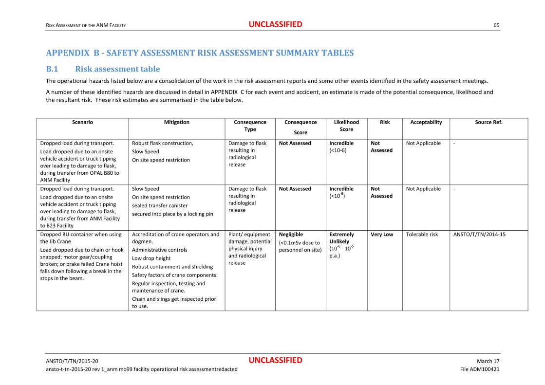
RISK ASSESSMENT OF THE ANM FACILITY UNCLASSIFIED 65
ANSTO/T/TN/2015‐20 UNCLASSIFIED March 17
ansto‐t‐tn‐2015‐20 rev 1_anm mo99 facility operational risk assessmentredacted File ADM100421
APPENDIXB‐SAFETYASSESSMENTRISKASSESSMENTSUMMARYTABLES
B.1 RiskassessmenttableThe operational hazards listed below are a consolidation of the work in the risk assessment reports and some other events identified in the safety assessment meetings.
A number of these identified hazards are discussed in detail in APPENDIX C for each event and accident, an estimate is made of the potential consequence, likelihood and the resultant risk. These risk estimates are summarised in the table below.
Scenario Mitigation Consequence Type
Consequence
Score
Likelihood Score
Risk Acceptability Source Ref.
Dropped load during transport.
Load dropped due to an onsite vehicle accident or truck tipping over leading to damage to flask, during transfer from OPAL B80 to ANM Facility
Robust flask construction,
Slow Speed
On site speed restriction
Damage to flask resulting in radiological release
Not Assessed Incredible (<10‐6)
Not Assessed
Not Applicable ‐
Dropped load during transport.
Load dropped due to an onsite vehicle accident or truck tipping over leading to damage to flask, during transfer from ANM Facility to B23 Facility
Slow Speed
On site speed restriction
sealed transfer canister
secured into place by a locking pin
Damage to flask resulting in radiological release
Not Assessed Incredible (<10‐6)
Not Assessed
Not Applicable ‐
Dropped BU container when using the Jib Crane
Load dropped due to chain or hook snapped; motor gear/coupling broken; or brake failed Crane hoist falls down following a break in the stops in the beam.
Accreditation of crane operators and dogmen.
Administrative controls
Low drop height
Robust containment and shielding
Safety factors of crane components.
Regular inspection, testing and maintenance of crane.
Chain and slings get inspected prior to use.
Plant/ equipment damage, potential physical injury and radiological release
Negligible
(<0.1mSv dose to personnel on site)
Extremely Unlikely (10‐6 ‐ 10‐5 p.a.)
Very Low Tolerable risk ANSTO/T/TN/2014‐15

RISK ASSESSMENT OF THE ANM FACILITY UNCLASSIFIED 66
ANSTO/T/TN/2015‐20 UNCLASSIFIED March 17
ansto‐t‐tn‐2015‐20 rev 1_anm mo99 facility operational risk assessmentredacted File ADM100421
Scenario Mitigation Consequence Type
Consequence
Score
Likelihood Score
Risk Acceptability Source Ref.
Dropped Manipulator when using the Front Cell Crane
Load dropped due to Chain or hook snapped; motor gear/coupling broken; or brake failed Crane hoist falls down following a break in the stops in the beam.
Accreditation of crane operators and dogmen.
Administrative controls
Safety factors of crane components.
Regular inspection, testing and maintenance of crane.
No possible derailment as the hoist is held captive.
Travel speed slow
Chain and slings get inspected prior to use.
Plant/ equipment damage, potential physical injury and radiological release
Negligible
(<0.1mSv dose to personnel on site)
Very Unlikely (10‐4 ‐ 10‐3 p.a.)
Very Low Tolerable risk ANSTO/T/TN/2014‐15
Dropping a Waste Holding tank during a monorail lift
Load dropped due to manual error in connecting the hooks to the tanks.
Chain or hook snapped;
Hoist falls down following a break in the stops in the beam.
Accreditation of crane operators and dogmen.
Administrative controls
Low drop height
Robust containment and shielding
Safety factors of crane components.
Regular inspection, testing, and maintenance of crane.
Chain and slings get inspected prior to use.
Plant/ equipment damage, potential physical injury and radiological release
Minor
(0.1‐1mSv dose to personnel on site).
Unlikely (10‐3 ‐ 10‐2 p.a.)
Very Low Tolerable risk ANSTO/T/TN/2014‐15
Dropping a carbon column during a monorail lift
Load dropped due to manual error in connecting the hooks to the tanks.
Chain or hook snapped;
Hoist falls down following a break in the stops in the beam.
Accreditation of crane operators and dogmen.
Administrative controls
Low drop height
Safety factors of crane components.
Regular inspection, testing and maintenance of crane.
Chain and slings get inspected prior to use.
Plant/ equipment damage, potential physical injury and radiological release
Negligible
(<0.1mSv dose to personnel on site)
Very Unlikely (10‐4 ‐ 10‐3 p.a.)
Very Low Tolerable risk ANSTO/T/TN/2014‐15

RISK ASSESSMENT OF THE ANM FACILITY UNCLASSIFIED 67
ANSTO/T/TN/2015‐20 UNCLASSIFIED March 17
ansto‐t‐tn‐2015‐20 rev 1_anm mo99 facility operational risk assessmentredacted File ADM100421
Scenario Mitigation Consequence Type
Consequence
Score
Likelihood Score
Risk Acceptability Source Ref.
Dropping a potentially contaminated item within the Active maintenance area as result of failure of the monorail lift Load dropped due to Chain or hook snapped; motor gear/coupling broken; or brake failed Crane hoist falls down following a break in the stops in the beam.
Accreditation of crane operators and dogmen.
Administrative controls
Low drop height
Safety factors of crane components.
Regular inspection, testing, and maintenance of crane.
Chain and slings get inspected prior to use.
Plant/ equipment damage, potential physical injury and radiological release
Negligible
(<0.1mSv dose to personnel on site)
Unlikely (10‐3 ‐ 10‐2 p.a.)
Very low Tolerable risk ANSTO/T/TN/2014‐15
Dropping a load within the Packing Cell and/or the ILSW Cell Load dropped due to human error or mechanical attachment.
Cell Containment
Administrative controls
Low drop height
Safety factors of crane components.
Regular inspection, testing and maintenance of lifting device
Plant/ equipment damage, potential, radiological release
Negligible
(<0.1mSv dose to personnel on site)
Likely (10‐2 ‐ 10‐1 p.a.)
Very Low Tolerable risk ANSTO/T/TN/2014‐15
Drop or uncontrolled lowering of irradiated target flask when using the Rear of the Cell Crane
Load dropped due to Rope or hook snapped; motor gear/coupling broken; or electrical failure of hoist motor.
Structural failure or deflection under overload or seismic events.
Trolley derailment.
Accreditation of crane operators and dogmen.
Administrative controls
Robust containment and shielding
Safety factors of crane components, with regular inspection, testing and maintenance of crane.
Designed to SL‐1 for operational availability; and SL‐2 against catastrophic collapse.
Structural design with safety factors.
Crane buffer stops.
Hoist ropes (Dual redundant)
Plant/ equipment damage, potential physical injury and radiological release
Severe
(100‐1000mSv dose to personnel on site)
Extremely Unlikely (10‐6 ‐ 10‐5 p.a.)
Low Tolerable risk ANSTO/T/TN/2014‐06

RISK ASSESSMENT OF THE ANM FACILITY UNCLASSIFIED 68
ANSTO/T/TN/2015‐20 UNCLASSIFIED March 17
ansto‐t‐tn‐2015‐20 rev 1_anm mo99 facility operational risk assessmentredacted File ADM100421
Scenario Mitigation Consequence Type
Consequence
Score
Likelihood Score
Risk Acceptability Source Ref.
Drop or uncontrolled lowering of flask containing SUF cups when using the Rear of the Cell Crane
Load dropped due to Rope or hook snapped; motor gear/coupling broken; or brake failed Crane hoist falls down following a break in the stops.
Accreditation of crane operators and dogmen.
Administrative controls
Robust containment and shielding
Safety factors of crane components, with regular inspection, testing and maintenance of crane.
Designed to SL‐1 for operational availability; and SL‐2 against catastrophic collapse.
Structural design with safety factors.
Crane buffer stops.
Hoist ropes (Dual redundant)
Plant/ equipment damage, potential physical injury and radiological release
Major
(20‐100mSv Dose to personnel on‐site)
Extremely Unlikely (10‐6 ‐ 10‐5 p.a.)
Low Tolerable risk ANSTO/T/TN/2014‐06
Drop or uncontrolled lowering of the ILW or LLW flask when using the Rear of the Cell Crane.
Load dropped due to Rope or hook snapped; motor gear/coupling broken; or brake failed Crane hoist falls down following a break in the stops.
Accreditation of crane operators and dogmen.
Administrative controls
Robust containment and shielding
Safety factors of crane components, with regular inspection, testing and maintenance of crane.
Designed to SL‐1 for operational availability; and SL‐2 against catastrophic collapse.
Structural design with safety factors.
Crane buffer stops.
Hoist ropes (Dual redundant)
Plant/ equipment damage, potential physical injury and radiological release
Moderate
(1‐20mSv dose to personnel on site
Highly Unlikely (10‐5 ‐ 10‐4 p.a.)
Very Low Tolerable risk ANSTO/T/TN/2014‐06
Loss of complete Red Primary Exhaust system (when there is no Mo‐99 production run in process) resulting in Airborne radioactive contamination inside hotcells
Active redundancy in exhaust fans and associated trains of filters and dampers.
Evacuation Alarm.
Radiation Negligible
(<0.1mSv dose to personnel on site)
Likely (10‐2 ‐ 10‐1 p.a.)
Very Low Tolerable risk ANSTO/T/TN/2014‐12
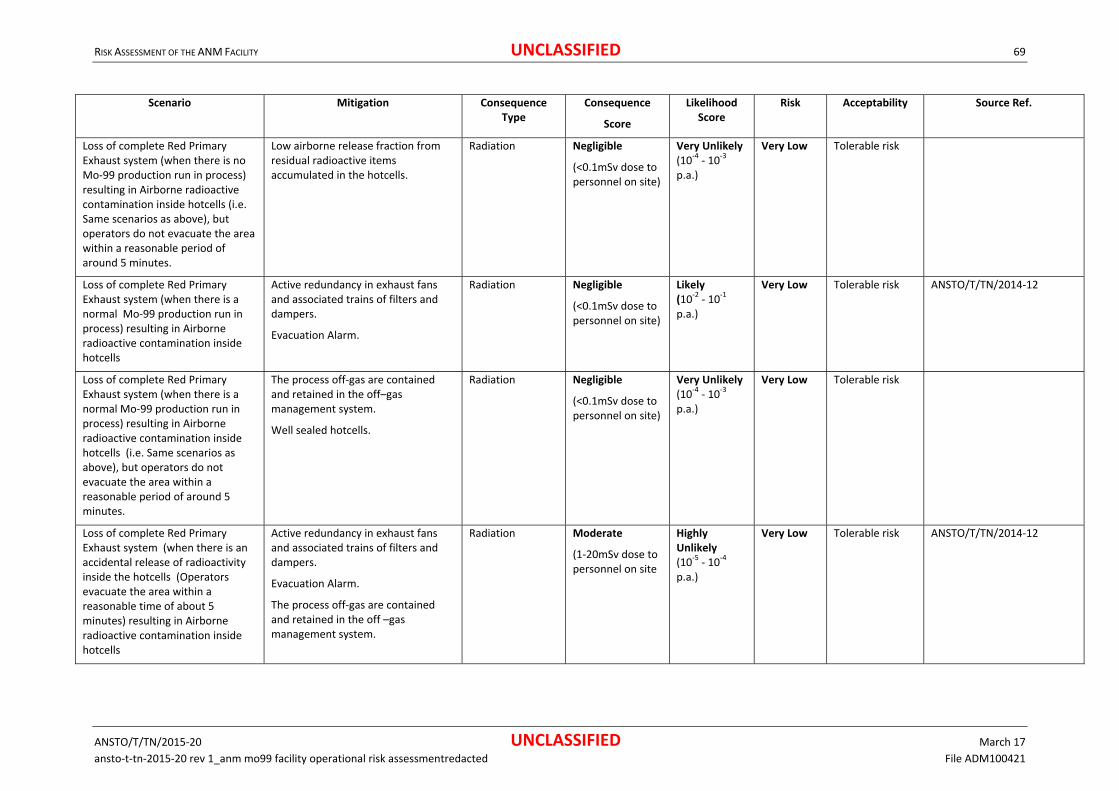
RISK ASSESSMENT OF THE ANM FACILITY UNCLASSIFIED 69
ANSTO/T/TN/2015‐20 UNCLASSIFIED March 17
ansto‐t‐tn‐2015‐20 rev 1_anm mo99 facility operational risk assessmentredacted File ADM100421
Scenario Mitigation Consequence Type
Consequence
Score
Likelihood Score
Risk Acceptability Source Ref.
Loss of complete Red Primary Exhaust system (when there is no Mo‐99 production run in process) resulting in Airborne radioactive contamination inside hotcells (i.e. Same scenarios as above), but operators do not evacuate the area within a reasonable period of around 5 minutes.
Low airborne release fraction from residual radioactive items accumulated in the hotcells.
Radiation Negligible
(<0.1mSv dose to personnel on site)
Very Unlikely (10‐4 ‐ 10‐3 p.a.)
Very Low Tolerable risk
Loss of complete Red Primary Exhaust system (when there is a normal Mo‐99 production run in process) resulting in Airborne radioactive contamination inside hotcells
Active redundancy in exhaust fans and associated trains of filters and dampers.
Evacuation Alarm.
Radiation Negligible
(<0.1mSv dose to personnel on site)
Likely (10‐2 ‐ 10‐1 p.a.)
Very Low Tolerable risk ANSTO/T/TN/2014‐12
Loss of complete Red Primary Exhaust system (when there is a normal Mo‐99 production run in process) resulting in Airborne radioactive contamination inside hotcells (i.e. Same scenarios as above), but operators do not evacuate the area within a reasonable period of around 5 minutes.
The process off‐gas are contained and retained in the off–gas management system.
Well sealed hotcells.
Radiation Negligible
(<0.1mSv dose to personnel on site)
Very Unlikely (10‐4 ‐ 10‐3 p.a.)
Very Low Tolerable risk
Loss of complete Red Primary Exhaust system (when there is an accidental release of radioactivity inside the hotcells (Operators evacuate the area within a reasonable time of about 5 minutes) resulting in Airborne radioactive contamination inside hotcells
Active redundancy in exhaust fans and associated trains of filters and dampers.
Evacuation Alarm.
The process off‐gas are contained and retained in the off –gas management system.
Radiation Moderate
(1‐20mSv dose to personnel on site
Highly Unlikely (10‐5 ‐ 10‐4 p.a.)
Very Low Tolerable risk ANSTO/T/TN/2014‐12
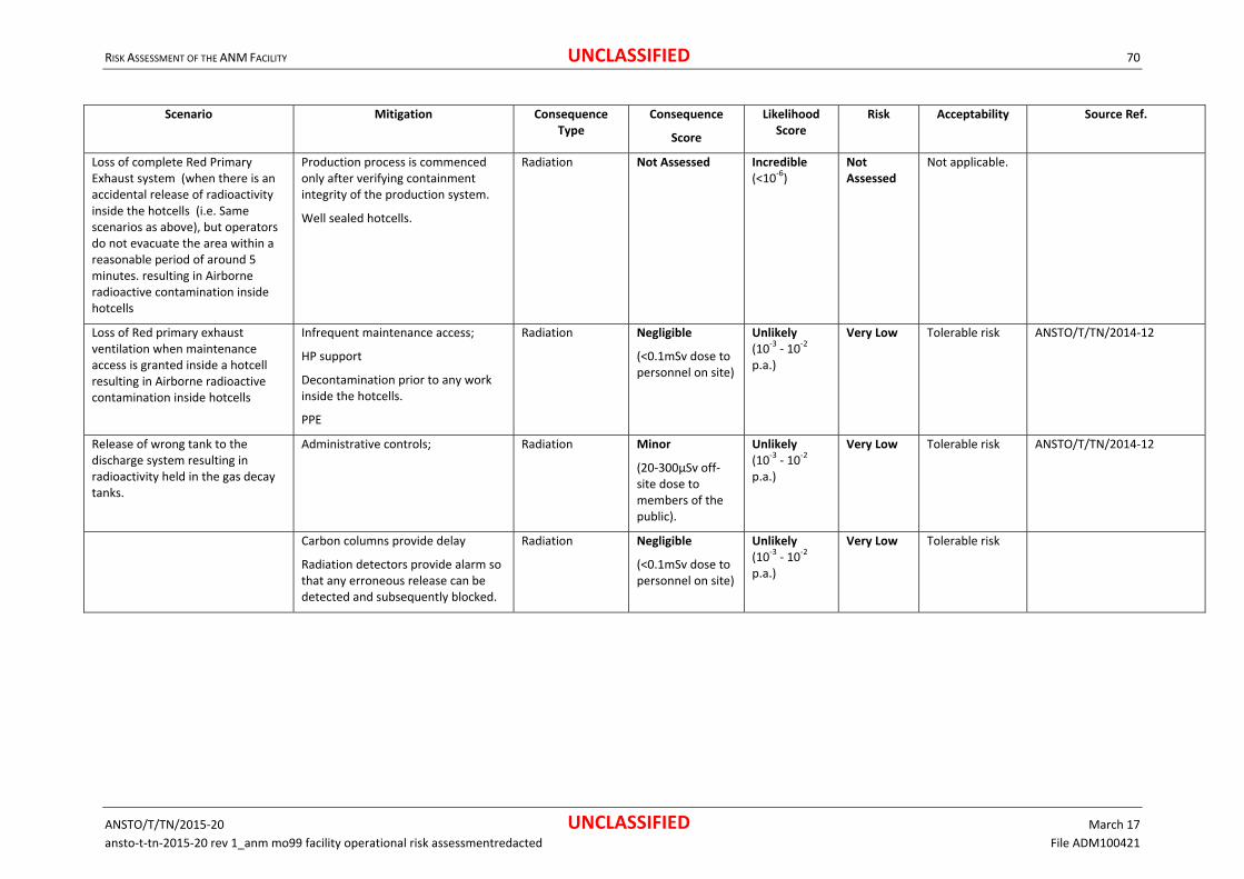
RISK ASSESSMENT OF THE ANM FACILITY UNCLASSIFIED 70
ANSTO/T/TN/2015‐20 UNCLASSIFIED March 17
ansto‐t‐tn‐2015‐20 rev 1_anm mo99 facility operational risk assessmentredacted File ADM100421
Scenario Mitigation Consequence Type
Consequence
Score
Likelihood Score
Risk Acceptability Source Ref.
Loss of complete Red Primary Exhaust system (when there is an accidental release of radioactivity inside the hotcells (i.e. Same scenarios as above), but operators do not evacuate the area within a reasonable period of around 5 minutes. resulting in Airborne radioactive contamination inside hotcells
Production process is commenced only after verifying containment integrity of the production system.
Well sealed hotcells.
Radiation Not Assessed Incredible (<10‐6)
Not Assessed
Not applicable.
Loss of Red primary exhaust ventilation when maintenance access is granted inside a hotcell resulting in Airborne radioactive contamination inside hotcells
Infrequent maintenance access;
HP support
Decontamination prior to any work inside the hotcells.
PPE
Radiation Negligible
(<0.1mSv dose to personnel on site)
Unlikely (10‐3 ‐ 10‐2 p.a.)
Very Low Tolerable risk ANSTO/T/TN/2014‐12
Release of wrong tank to the discharge system resulting in radioactivity held in the gas decay tanks.
Administrative controls; Radiation
Minor
(20‐300µSv off‐ site dose to members of the public).
Unlikely (10‐3 ‐ 10‐2 p.a.)
Very Low
Tolerable risk ANSTO/T/TN/2014‐12
Carbon columns provide delay
Radiation detectors provide alarm so that any erroneous release can be detected and subsequently blocked.
Radiation Negligible
(<0.1mSv dose to personnel on site)
Unlikely (10‐3 ‐ 10‐2 p.a.)
Very Low Tolerable risk

RISK ASSESSMENT OF THE ANM FACILITY UNCLASSIFIED 71
ANSTO/T/TN/2015‐20 UNCLASSIFIED March 17
ansto‐t‐tn‐2015‐20 rev 1_anm mo99 facility operational risk assessmentredacted File ADM100421
Scenario Mitigation Consequence Type
Consequence
Score
Likelihood Score
Risk Acceptability Source Ref.
Loss of containment of process off‐gas following an over‐pressurisation resulting in Air borne radioactive contamination outside hotcells
Any over pressurisation in the dissolution system is relieved by bursting discs but the gases are still contained in the gas tanks.
Gas transfers are carried out using vacuum, so any leaks in the gas transfer lines will cause air to be drawn in and not release of gas.
Gas transfer lines are rated for 1000kPa.
Radiation Negligible
(<0.1mSv dose to personnel on site)
Unlikely (10‐3 ‐ 10‐2 p.a.)
Very Low Tolerable risk ANSTO/T/TN/2014‐12
Activity in the stack discharges Airborne contamination in the building resulting from backflows.
HEPA filters
The outlet damper of the secondary ventilation system is closed on stoppage.
Radiation Negligible
(<0.1mSv dose to personnel on site)
Unlikely (10‐3 ‐ 10‐2 p.a.)
Very Low Tolerable risk ANSTO/T/TN/2014‐12
Possibility of electrical shock during maintenance work.
Unit tested and tagged.
Electrical work performed by licensed electricians.
Isolation prior to work.
Physical injury Severe or Major Extremely Unlikely (10‐6 ‐ 10‐5 p.a.)
Medium Tolerable. Risk is considered ALARP with standard ANSTO precautions and safeguards in place.
ANSTO/T/TN/2014‐15
Radioactive gases leaked into hotcell containment resulting in contamination release.
Process containment pressure below cell pressure.
Process controls and safety interlocks prevent possibility abnormal events causing leaks into hotcell containment.
Radiation Minor
(20‐300µSv off‐ site dose to members of the public).
Unlikely (10‐3 ‐ 10‐2 p.a.)
Low Tolerable risk ANSTO/T/TN/2015‐16
Legal Compliance Minor Unlikely (10‐3 ‐ 10‐2 p.a.)
Low Tolerable risk ANSTO/T/TN/2015‐16

RISK ASSESSMENT OF THE ANM FACILITY UNCLASSIFIED 72
ANSTO/T/TN/2015‐20 UNCLASSIFIED March 17
ansto‐t‐tn‐2015‐20 rev 1_anm mo99 facility operational risk assessmentredacted File ADM100421
Scenario Mitigation Consequence Type
Consequence
Score
Likelihood Score
Risk Acceptability Source Ref.
Spill of radioactive liquid into hotcell containment resulting in contamination release.
Spills contained within hotcell containment.
Valves and pipes use swaged connections designed for much higher pressures than operating conditions.
Liquids not volatile
radiological release
Negligible
(< 20µSv off‐ site dose to members of the public).
Unlikely (10‐3 ‐ 10‐2 p.a.)
Very Low Tolerable risk ANSTO/T/TN/2015‐16
Legal Compliance Minor Unlikely (10‐3 ‐ 10‐2 p.a.)
Low Tolerable risk ANSTO/T/TN/2015‐16
Over pressurisation of dissolver leading to rupture or significant leaks from seals result in contamination release.
Pressure monitored and overpressure causes the reaction to cool down.
Possibility of manual intervention to prevent over pressurisation.
AVS discharge to stack
hotcell containment minimises airborne contamination in the front of cell.
radiological release
Minor
(20‐300µSv off‐ site dose to members of the public).
Extremely Unlikely (10‐6 ‐ 10‐5 p.a.)
Very Low Tolerable risk ANSTO/T/TN/2015‐16
Legal Compliance Moderate Extremely Unlikely (10‐6 ‐ 10‐5 p.a.)
Low Tolerable risk ANSTO/T/TN/2015‐16
Hydrogen fire or explosion inside hotcell containment resulting in contamination release.
Bursting discs
AVS extract
No ready source of ignition inside hotcell containment.
radiological release
Not Assessed Incredible (<10‐6)
Not Assessed
No applicable. ANSTO/T/TN/2015‐16
Legal compliance Not Assessed Incredible (<10‐6)
Not Assessed
No applicable. ANSTO/T/TN/2015‐16
Physical injury Not Assessed Incredible (<10‐6)
Not Assessed
No applicable. ANSTO/T/TN/2015‐16
Hydrogen fire or explosion in the AVS exhaust ducts due to hydrogen conversion failure and subsequent discharge via AVS resulting in contamination release.
Control safety interlocks.
Exothermic reaction ensures continuation of conversion reaction even if heating fails
Massive dilution via AVS extract
radiological release
Negligible
(<0.1mSv dose to personnel on site)
Highly Unlikely (10‐5 ‐ 10‐4 p.a.)
Very Low Tolerable risk ANSTO/T/TN/2015‐16
Legal compliance Moderate Highly Unlikely (10‐5 ‐ 10‐4 p.a.)
Low Tolerable risk. ANSTO/T/TN/2015‐16

RISK ASSESSMENT OF THE ANM FACILITY UNCLASSIFIED 73
ANSTO/T/TN/2015‐20 UNCLASSIFIED March 17
ansto‐t‐tn‐2015‐20 rev 1_anm mo99 facility operational risk assessmentredacted File ADM100421
Scenario Mitigation Consequence Type
Consequence
Score
Likelihood Score
Risk Acceptability Source Ref.
Entry of air into process containment during dissolution and possible explosion resulting in contamination release.
Reliable control and potation against over temperature.
Hydrogen conversion is closely monitored and recorded in batch sheets.
radiological release
Not Assessed Incredible (<10‐6)
Not Assessed
Not applicable. ANSTO/T/TN/2015‐16
Legal compliance Not Assessed Incredible (<10‐6)
Not Assessed
Not applicable ANSTO/T/TN/2015‐16
Physical injury Not Assessed Incredible (<10‐6)
Not Assessed
Not applicable ANSTO/T/TN/2015‐16
Damage to process tanks or piping due to seismic event resulting in contamination release.
hotcell containment designed to SL‐2.
The attachment of the process vessels to the hotcell containment box are also designed SL‐2.
Flexible piping used to connect various process tanks to manifolds.
radiological release
Minor
(20‐300µSv off‐ site dose to members of the public).
Highly Unlikely (10‐5 ‐ 10‐4 p.a.)
Very Low Tolerable risk ANSTO/T/TN/2015‐16
radiological release
Major
(20‐100mSv Dose to personnel on‐site)
Highly Unlikely (10‐5 ‐ 10‐4 p.a.)
Low Tolerable risk ANSTO/T/TN/2015‐16
Legal Compliance Moderate Highly Unlikely (10‐5 ‐ 10‐4 p.a.)
Low Tolerable risk ANSTO/T/TN/2015‐16
Failure of the hotcell Penetration Sealing due Mechanical impact, wear and tear (manipulator booting), corrosion, or Seismic Event leading to compromise of the hotcell integrity.
Suitable material (for alkaline and acidity)
AVS system will still be functional if an impact occur to minimise contamination
radiological release
Negligible (<0.1mSv dose to personnel on site)
Likely (10‐1 ‐ 10‐2 pa)
Very Low Tolerable risk ANSTO/T/TN/2014‐13
Spurious opening of the modulating valves of the AVS outlet piping of hotcells coincident with spurious closing of the inlet valves could cause excess negative pressure resulting in possible implosion damage.
DCELL ‐ diverse and redundant vacuum break devices
Other hotcells ‐ single vacuum break device is used on the outlet pipe or on the outlet header pipe
Two modulating valves on the AVS exhaust
radiological release
Not Assessed Incredible (<10‐6)
Not Assessed
Not applicable

RISK ASSESSMENT OF THE ANM FACILITY UNCLASSIFIED 74
ANSTO/T/TN/2015‐20 UNCLASSIFIED March 17
ansto‐t‐tn‐2015‐20 rev 1_anm mo99 facility operational risk assessmentredacted File ADM100421
Scenario Mitigation Consequence Type
Consequence
Score
Likelihood Score
Risk Acceptability Source Ref.
Excess positive pressure in DCELL or HCELL resulting in damage to containment. Inlet and outlet valves both close spuriously and hence causing heating up of the contained volume of air in these cells due to heart sources present.
Redundancy of valves.
Pressure relief device
radiological release
Not Assessed Incredible (<10‐6)
Not Assessed
Not applicable ANSTO/T/TN/2014‐13
Over temperature in DCELL or HCELL causing damage to containment. Loss of AVS exhaust in DCELL or HCELL, due to total power failure (both duty and standby) to the AVS fans or the AVS extraction failure.
insufficient large heat sources to allow excessive positive pressure due to internal heating
radiological release
Minor
(0.1‐1mSv dose to personnel on site).
Likely (10‐2 ‐ 10‐1 pa)
Very Low Tolerable risk ANSTO/T/TN/2014‐13
Loss of hotcell containment due to spurious operation of vacuum break devices. Spurious operation of vacuum break devices causing negative pressure
simple and passive devices
inspected regularly
AVS Alarm will detect loss of containment
radiological release
Negligible (<0.1mSv dose to personnel on site)
Likely (10‐2 ‐ 10‐1 pa)
Low Tolerable risk ANSTO/T/TN/2014‐13
Spill of the Intermediate level liquid waste due to failure of the decay or holding tanks (only credible failure modes identified for the decay or holding tanks are by corrosion or aseismic event_
All pipes and tanks have been designed for corrosion with a lifetime of 30 years
Located underground
Surrounded by concrete
liquid detection probes to detect such a spill
Bunker connected to AVS
radiological release(due to a spill)
Negligible (<0.1mSv dose to personnel on site)
Unlikely (10‐3 ‐ 10‐2 p.a.)
Very Low Tolerable risk ANSTO/T/TN/2014‐13
radiological release(due to seismic)
Moderate
(1‐20mSv dose to personnel on site
Highly Unlikely (10‐5 ‐ 10‐4 p.a.)
Very Low Tolerable risk ANSTO/T/TN/2014‐13
Environmental (due to seismic)
Major
(Medium term damage confined to buffer zone).
Highly Unlikely (10‐5 ‐ 10‐4 p.a.)
Low Tolerable risk ANSTO/T/TN/2014‐13

RISK ASSESSMENT OF THE ANM FACILITY UNCLASSIFIED 75
ANSTO/T/TN/2015‐20 UNCLASSIFIED March 17
ansto‐t‐tn‐2015‐20 rev 1_anm mo99 facility operational risk assessmentredacted File ADM100421
Scenario Mitigation Consequence Type
Consequence
Score
Likelihood Score
Risk Acceptability Source Ref.
AVS connection isolated in error resulting in over pressurisation of the waste decay tank. Pressure as a result of PULSAIR nitrogen stirring
nitrogen pulse system is interlocked against the tank pressure
fixed volume of nitrogen
system designed so it is not possible to connect both the nitrogen supply and the PULSAIR system simultaneously.
pressure‐regulated system
radiological release
Negligible (<0.1mSv dose to personnel on site)
Extremely Unlikely (10‐6 ‐ 10‐5 p.a.)
Very Low Tolerable risk ANSTO/T/TN/2014‐13
Operational/ compliance
Moderate
(loss of production <1 month / report to regulator).
Extremely Unlikely (10‐6 ‐ 10‐5 p.a.)
Very Low Tolerable risk ANSTO/T/TN/2014‐13
dropped ‘dirty’ filter during change over leading to puncturing of the bag and re‐suspension of particulate activity on the filter
experienced maintenance engineers
local radiological monitoring
safe‐change filter housings
radiological release
Moderate
(1‐20mSv dose to personnel on site)
Very Unlikely
(10‐4 ‐ 10‐3 p.a.)
Low Tolerable risk
A fire inside the hotcells Radioactivity inside hotcells
No flammable materials (liquids/solids) used or stored inside the hotcell.
Except for HCELL (containing the hydrogen converter) the other cells do not
radiological release
Minor
(20‐300µSv off‐ site dose to members of the public).
Highly Unlikely (10‐5 ‐ 10‐4 p.a.)
Very Low
Tolerable risk ANSTO/T/TN/2014‐12
Have any high temperature processes that could be a source of ignition.
Hydrogen is produced in DCELL but converted to ensure H2O in an online process in a sealed system.
HEPA filters, Carbon – Iodine filters
radiological release
Moderate
(1‐20mSv dose to personnel on site
Highly Unlikely (10‐5 ‐ 10‐4 p.a.)
Very Low Tolerable risk
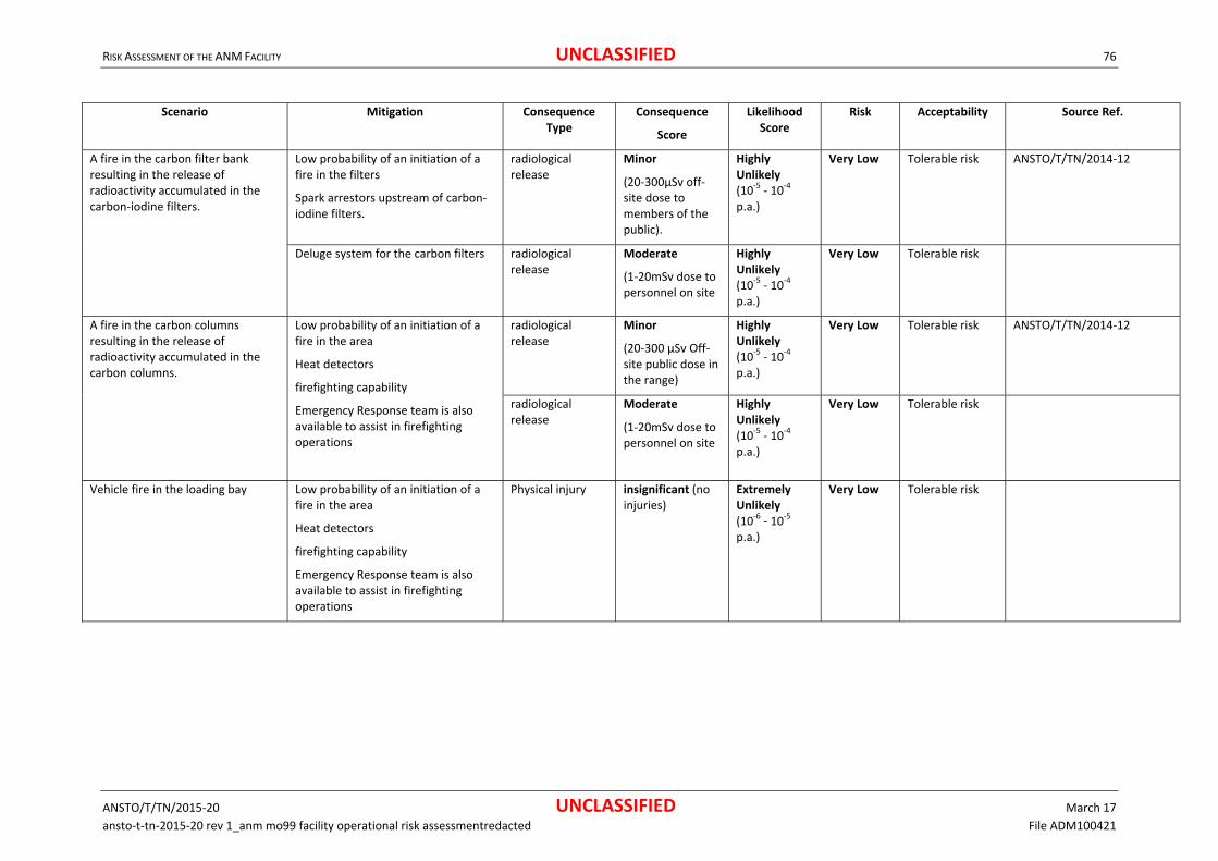
RISK ASSESSMENT OF THE ANM FACILITY UNCLASSIFIED 76
ANSTO/T/TN/2015‐20 UNCLASSIFIED March 17
ansto‐t‐tn‐2015‐20 rev 1_anm mo99 facility operational risk assessmentredacted File ADM100421
Scenario Mitigation Consequence Type
Consequence
Score
Likelihood Score
Risk Acceptability Source Ref.
A fire in the carbon filter bank resulting in the release of radioactivity accumulated in the carbon‐iodine filters.
Low probability of an initiation of a fire in the filters
Spark arrestors upstream of carbon‐iodine filters.
radiological release
Minor
(20‐300µSv off‐ site dose to members of the public).
Highly Unlikely (10‐5 ‐ 10‐4 p.a.)
Very Low
Tolerable risk ANSTO/T/TN/2014‐12
Deluge system for the carbon filters
radiological release
Moderate
(1‐20mSv dose to personnel on site
Highly Unlikely (10‐5 ‐ 10‐4 p.a.)
Very Low Tolerable risk
A fire in the carbon columns resulting in the release of radioactivity accumulated in the carbon columns.
Low probability of an initiation of a fire in the area
Heat detectors
firefighting capability
Emergency Response team is also available to assist in firefighting operations
radiological release
Minor
(20‐300 µSv Off‐ site public dose in the range)
Highly Unlikely (10‐5 ‐ 10‐4 p.a.)
Very Low Tolerable risk ANSTO/T/TN/2014‐12
radiological release
Moderate
(1‐20mSv dose to personnel on site
Highly Unlikely (10‐5 ‐ 10‐4 p.a.)
Very Low Tolerable risk
Vehicle fire in the loading bay Low probability of an initiation of a fire in the area
Heat detectors
firefighting capability
Emergency Response team is also available to assist in firefighting operations
Physical injury insignificant (no injuries)
Extremely Unlikely (10‐6 ‐ 10‐5 p.a.)
Very Low Tolerable risk

RISK ASSESSMENT OF THE ANM FACILITY UNCLASSIFIED 77
ANSTO/T/TN/2015‐20 UNCLASSIFIED March 17
ansto‐t‐tn‐2015‐20 rev 1_anm mo99 facility operational risk assessmentredacted File ADM100421
Scenario Mitigation Consequence Type
Consequence
Score
Likelihood Score
Risk Acceptability Source Ref.
Fire in the cell face area resulting in the release of radioactivity
Low probability of an initiation of a fire in the area
Heat detectors
firefighting capability
Emergency Response team is also available to assist in firefighting operations
Physical injury Insignificant (no injuries)
Very Unlikely (10‐4 ‐ 10‐3 p.a.)
Very Low Tolerable risk
Fire in the Active maintenance area resulting in the release of radioactivity
Low probability of an initiation of a fire in the area
Heat detectors
firefighting capability
Emergency Response team is also available to assist in firefighting operations
Physical injury insignificant (no injuries)
Very Unlikely (10‐4 ‐ 10‐3 p.a.)
Very Low Tolerable risk
Fire in the ventilation plant room would result in the loss of the ventilation within the ANM Facility only.
Loss of negative pressure
spread of contamination into the cell face and rear of cell area due to leakage from the hotcells
Low probability of an initiation of a fire in the area
Heat detectors
firefighting capability
Emergency Response team is also available to assist in firefighting operations
radiological release
Minor
(20‐300µSv off‐ site dose to members of the public).
Very Unlikely (10‐4 ‐ 10‐3 p.a.)
Very Low Tolerable risk
radiological release
Moderate
(1‐20mSv dose to personnel on site)
Very Unlikely (10‐4 ‐ 10‐3 p.a.)
Low Tolerable risk
Fire in the QC Labs resulting in the release of radioactivity
Low probability of an initiation of a fire in the area
Heat detectors
firefighting capability
Emergency Response team is also available to assist in firefighting operations
Physical injury insignificant (no injuries)
Very Unlikely (10‐4 ‐10‐3 p.a.)
Very Low Tolerable risk
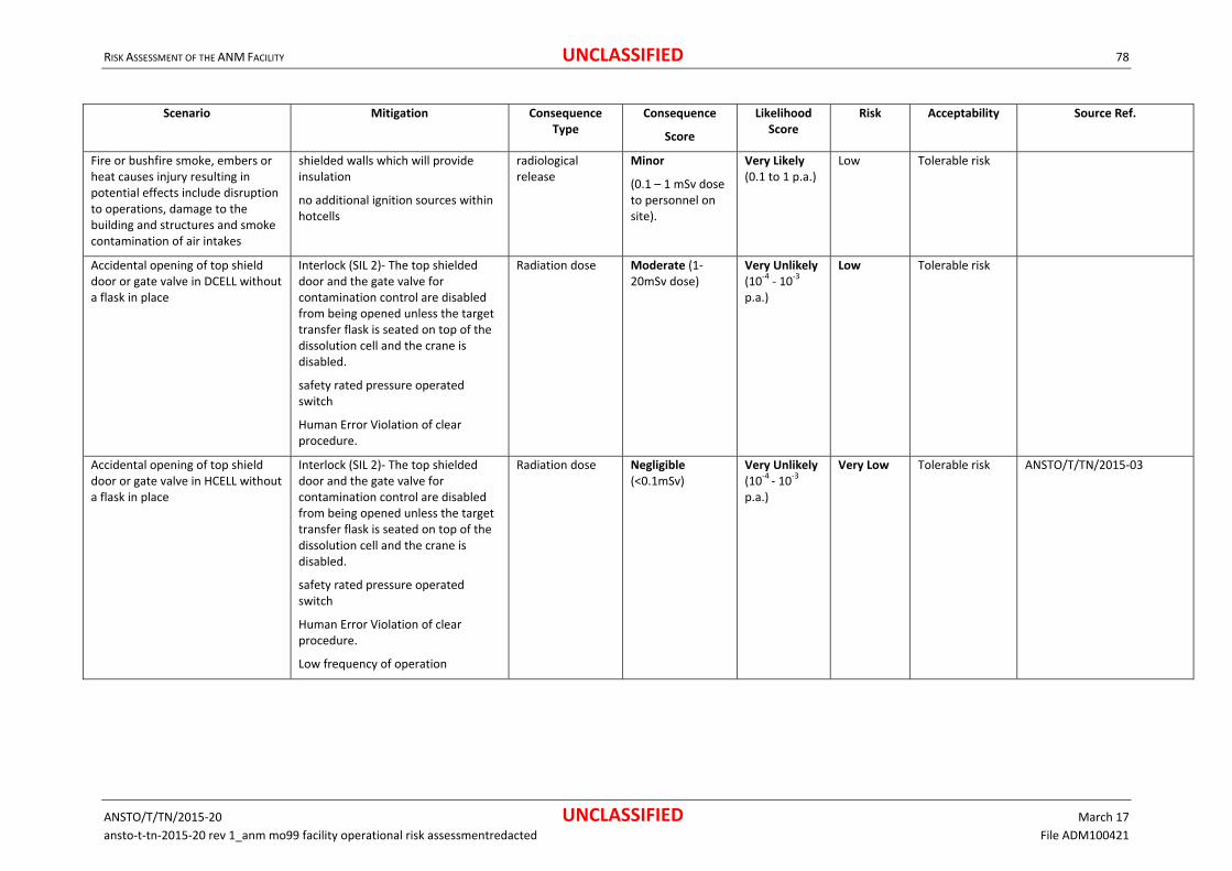
RISK ASSESSMENT OF THE ANM FACILITY UNCLASSIFIED 78
ANSTO/T/TN/2015‐20 UNCLASSIFIED March 17
ansto‐t‐tn‐2015‐20 rev 1_anm mo99 facility operational risk assessmentredacted File ADM100421
Scenario Mitigation Consequence Type
Consequence
Score
Likelihood Score
Risk Acceptability Source Ref.
Fire or bushfire smoke, embers or heat causes injury resulting in potential effects include disruption to operations, damage to the building and structures and smoke contamination of air intakes
shielded walls which will provide insulation
no additional ignition sources within hotcells
radiological release
Minor
(0.1 – 1 mSv dose to personnel on site).
Very Likely (0.1 to 1 p.a.)
Low Tolerable risk
Accidental opening of top shield door or gate valve in DCELL without a flask in place
Interlock (SIL 2)‐ The top shielded door and the gate valve for contamination control are disabled from being opened unless the target transfer flask is seated on top of the dissolution cell and the crane is disabled.
safety rated pressure operated switch
Human Error Violation of clear procedure.
Radiation dose Moderate (1‐20mSv dose)
Very Unlikely (10‐4 ‐ 10‐3 p.a.)
Low Tolerable risk
Accidental opening of top shield door or gate valve in HCELL without a flask in place
Interlock (SIL 2)‐ The top shielded door and the gate valve for contamination control are disabled from being opened unless the target transfer flask is seated on top of the dissolution cell and the crane is disabled.
safety rated pressure operated switch
Human Error Violation of clear procedure.
Low frequency of operation
Radiation dose Negligible (<0.1mSv)
Very Unlikely (10‐4 ‐ 10‐3 p.a.)
Very Low Tolerable risk ANSTO/T/TN/2015‐03
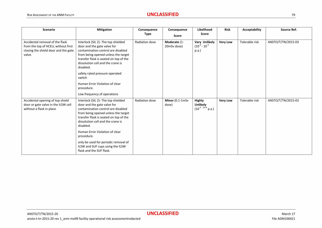
RISK ASSESSMENT OF THE ANM FACILITY UNCLASSIFIED 79
ANSTO/T/TN/2015‐20 UNCLASSIFIED March 17
ansto‐t‐tn‐2015‐20 rev 1_anm mo99 facility operational risk assessmentredacted File ADM100421
Scenario Mitigation Consequence Type
Consequence
Score
Likelihood Score
Risk Acceptability Source Ref.
Accidental removal of the flask from the top of HCELL without first closing the shield door and the gate valve.
Interlock (SIL 2)‐ The top shielded door and the gate valve for contamination control are disabled from being opened unless the target transfer flask is seated on top of the dissolution cell and the crane is disabled.
safety rated pressure operated switch
Human Error Violation of clear procedure.
Low frequency of operations
Radiation dose Moderate (1‐20mSv dose)
Very Unlikely (10‐4 ‐ 10‐3 p.a.)
Very Low Tolerable risk ANSTO/T/TN/2015‐03
Accidental opening of top shield door or gate valve in the ILSW cell without a flask in place
Interlock (SIL 2)‐ The top shielded door and the gate valve for contamination control are disabled from being opened unless the target transfer flask is seated on top of the dissolution cell and the crane is disabled.
Human Error Violation of clear procedure.
only be used for periodic removal of ILSW and SUF cups using the ILSW flask and the SUF flask.
Radiation dose Minor (0.1‐1mSv dose)
Highly Unlikely (10‐5 ‐ 10‐4 p.a.)
Very Low Tolerable risk ANSTO/T/TN/2015‐03

RISK ASSESSMENT OF THE ANM FACILITY UNCLASSIFIED 80
ANSTO/T/TN/2015‐20 UNCLASSIFIED March 17
ansto‐t‐tn‐2015‐20 rev 1_anm mo99 facility operational risk assessmentredacted File ADM100421
Scenario Mitigation Consequence Type
Consequence
Score
Likelihood Score
Risk Acceptability Source Ref.
Accidental removal of the flask from the top of ILSW cell without first closing the shield door and the gate valve
Interlock (SIL 2)‐ The top shielded door and the gate valve for contamination control are disabled from being opened unless the target transfer flask is seated on top of the dissolution cell and the crane is disabled.
Human Error Violation of clear procedure.
only be used for periodic removal of ILSW and SUF cups using the ILSW flask and the SUF flask.
Radiation dose Minor (0.1‐1mSv dose)
Unlikely (<10‐3 ‐ 10‐2 p.a.)
Low Tolerable risk ANSTO/T/TN/2015‐03
Accidental opening of the shield door of a hotcell using the PADIRAC PTS without a PADIRAC cask
No direct shine path could be present between a radioactive source inside the hotcell and an operator in the rear of cell area.
Human Error Violation of clear procedure. (i) The PTS without the flask being pushed back to engage with the hotcell PMP door; and (ii) An operator raises the PTS (without the flask in place) by holding the pushbutton control for a period of about 30 seconds thereby opening the PMP door.
Radiation dose Not Assessed Incredible (<10‐6 p.a.)
Not Assessed
Tolerable risk ANSTO/T/TN/2015‐03
Opening the PADIRAC cask door with radioactive items inside
Human Error Violation of clear procedure.
Appropriate precautions are in place and undertaken.
Portable monitors available.
Radiation monitors within area.
Radiation dose Moderate (1‐20mSv dose)
Very Unlikely (10‐4 – 10‐3 p.a.)
Low Tolerable risk ANSTO/T/TN/2015‐03

RISK ASSESSMENT OF THE ANM FACILITY UNCLASSIFIED 81
ANSTO/T/TN/2015‐20 UNCLASSIFIED March 17
ansto‐t‐tn‐2015‐20 rev 1_anm mo99 facility operational risk assessmentredacted File ADM100421
Scenario Mitigation Consequence Type
Consequence
Score
Likelihood Score
Risk Acceptability Source Ref.
Accidental opening of the DPTE door of a hotcell without a DPTE container pushed against the door opening
Interlock (SIL 1) prevents opening unless the DPTE container is pushed against the hotcell port forming a seal
AVS Red primary exhaust would keep the cell negative pressure to prevent air borne contamination outside the cell
Radiation dose Negligible (<0.1mSv inhalation dose)
Likely (10‐2 ‐ 10‐1 p.a.)
Low Tolerable risk ANSTO/T/TN/2015‐03
Opening the shield door of the B(U) port when there is high activity inside the packaging cell.
No direct shine to operator
Human Error Violation of clear procedure.
Interlock (SIL 2) prevents opening the shield door when the radiation level is above a safe level (to be determined during hot commissioning).
Radiation dose Minor (1‐20mSv) Unlikely (10‐3 ‐ 10‐2 p.a.)
Very Low Tolerable risk ANSTO/T/TN/2015‐03
High activity source passed through to the Packaging cell when the shield door is open
No direct shine to operator
Human Error Violation of clear procedure.
Interlock (SIL 2) prevents opening of the pass‐through door unless the shield door is closed. With
Radiation dose Minor (1 ‐ 20mSv) Unlikely (10‐3 ‐ 10‐2 p.a.)
Very Low Tolerable risk ANSTO/T/TN/2015‐03
Dropping Mo‐99 product container through the B(U) port door without a B(U) IC docked in the B(U) port of
Interlock (SIL 2) provisions preventing this accident includes:
Radiation dose Moderate (1 ‐ 20mSv)
Very Unlikely (10‐4 ‐10‐3 p.a.)
Very Low Tolerable risk ANSTO/T/TN/2015‐03
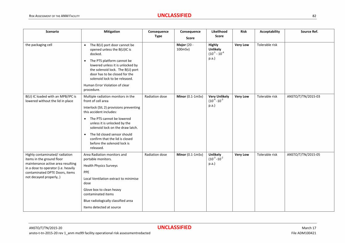
RISK ASSESSMENT OF THE ANM FACILITY UNCLASSIFIED 82
ANSTO/T/TN/2015‐20 UNCLASSIFIED March 17
ansto‐t‐tn‐2015‐20 rev 1_anm mo99 facility operational risk assessmentredacted File ADM100421
Scenario Mitigation Consequence Type
Consequence
Score
Likelihood Score
Risk Acceptability Source Ref.
the packaging cell The B(U) port door cannot be opened unless the B(U)IC is docked.
The PTS platform cannot be lowered unless it is unlocked by the solenoid lock. The B(U) port door has to be closed for the solenoid lock to be released.
Human Error Violation of clear procedure.
Major (20 ‐ 100mSv)
Highly Unlikely (10‐5 ‐ 10‐4 p.a.)
Very Low Tolerable risk
B(U) IC loaded with an MPB/IPC is lowered without the lid in place
Multiple radiation monitors in the front of cell area
Interlock (SIL 2) provisions preventing this accident includes:
The PTS cannot be lowered unless it is unlocked by the solenoid lock on the draw latch.
The lid closed sensor should confirm that the lid is closed before the solenoid lock is released.
Radiation dose Minor (0.1‐1mSv) Very Unlikely (10‐4 ‐10‐3 p.a.)
Very Low Tolerable risk ANSTO/T/TN/2015‐03
Highly contaminated/ radiation items in the ground floor maintenance active area resulting in a dose to operator (i.e. heavily contaminated DPTE Doors, items not decayed properly, )
Area Radiation monitors and portable monitors.
Health Physics Surveys
PPE
Local Ventilation extract to minimise dose
Glove box to clean heavy contaminated items
Blue radiologically classified area
Items detected at source
Radiation dose Minor (0.1‐1mSv) Unlikely (10‐3 ‐10‐2 p.a.)
Very Low Tolerable risk ANSTO/T/TN/2015‐05
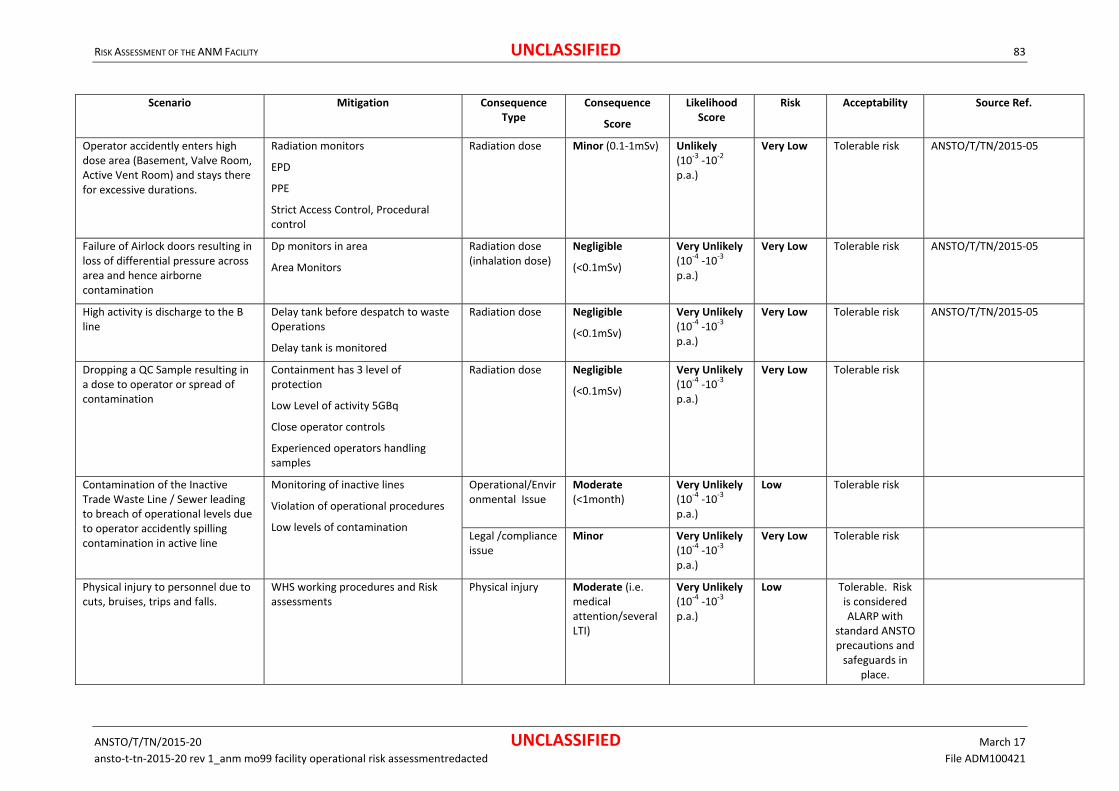
RISK ASSESSMENT OF THE ANM FACILITY UNCLASSIFIED 83
ANSTO/T/TN/2015‐20 UNCLASSIFIED March 17
ansto‐t‐tn‐2015‐20 rev 1_anm mo99 facility operational risk assessmentredacted File ADM100421
Scenario Mitigation Consequence Type
Consequence
Score
Likelihood Score
Risk Acceptability Source Ref.
Operator accidently enters high dose area (Basement, Valve Room, Active Vent Room) and stays there for excessive durations.
Radiation monitors
EPD
PPE
Strict Access Control, Procedural control
Radiation dose Minor (0.1‐1mSv) Unlikely (10‐3 ‐10‐2 p.a.)
Very Low Tolerable risk ANSTO/T/TN/2015‐05
Failure of Airlock doors resulting in loss of differential pressure across area and hence airborne contamination
Dp monitors in area
Area Monitors
Radiation dose (inhalation dose)
Negligible
(<0.1mSv)
Very Unlikely (10‐4 ‐10‐3 p.a.)
Very Low Tolerable risk ANSTO/T/TN/2015‐05
High activity is discharge to the B line
Delay tank before despatch to waste Operations
Delay tank is monitored
Radiation dose Negligible
(<0.1mSv)
Very Unlikely (10‐4 ‐10‐3 p.a.)
Very Low Tolerable risk ANSTO/T/TN/2015‐05
Dropping a QC Sample resulting in a dose to operator or spread of contamination
Containment has 3 level of protection
Low Level of activity 5GBq
Close operator controls
Experienced operators handling samples
Radiation dose Negligible
(<0.1mSv)
Very Unlikely (10‐4 ‐10‐3 p.a.)
Very Low Tolerable risk
Contamination of the Inactive Trade Waste Line / Sewer leading to breach of operational levels due to operator accidently spilling contamination in active line
Monitoring of inactive lines
Violation of operational procedures
Low levels of contamination
Operational/Environmental Issue
Moderate (<1month)
Very Unlikely (10‐4 ‐10‐3 p.a.)
Low Tolerable risk
Legal /compliance issue
Minor Very Unlikely (10‐4 ‐10‐3 p.a.)
Very Low Tolerable risk
Physical injury to personnel due to cuts, bruises, trips and falls.
WHS working procedures and Risk assessments
Physical injury Moderate (i.e. medical attention/several LTI)
Very Unlikely (10‐4 ‐10‐3 p.a.)
Low Tolerable. Risk is considered ALARP with
standard ANSTO precautions and safeguards in
place.

RISK ASSESSMENT OF THE ANM FACILITY UNCLASSIFIED 84
ANSTO/T/TN/2015‐20 UNCLASSIFIED March 17
ansto‐t‐tn‐2015‐20 rev 1_anm mo99 facility operational risk assessmentredacted File ADM100421
Scenario Mitigation Consequence Type
Consequence
Score
Likelihood Score
Risk Acceptability Source Ref.
working at height faults around the access hatch, carbon column, and valve room plus other areas
WHS working procedures and Risk assessments
Physical injury Major Highly Unlikely (10‐5 ‐10‐4 p.a.)
Low Tolerable. Risk is considered ALARP with
standard ANSTO precautions and safeguards in
place.
Possibility of electrical shock during maintenance work.
Unit tested and tagged.
Electrical work performed by licensed electricians.
Isolation prior to work.
Physical injury Major Extremely Unlikely (10‐6 ‐10‐5 p.a.)
Low Tolerable. Risk is considered ALARP with
standard ANSTO precautions and safeguards in
place.
Water leaks form ruptured or damaged pipes into labs, active areas, electrical units and systems
Leak tested during installation, condition inspection
Operational delays
Moderate Highly Unlikely (10‐5 ‐ 10‐4 pa)
Low Tolerable. Risk is considered ALARP with
standard ANSTO precautions and safeguards in
place.
Fire/ explosion in the Gas Cylinder Store during unloading, storage and transport
Rocketing Cylinder (Unloading)
Adequate filling station and space available.
Cylinders are appropriately supported
Physical injury Moderate (Injuries requiring medical attention)
Very Unlikely (10‐4 ‐ 10‐3 p.a.)
Low Tolerable risk
Risk of Explosion (Storage) Valve cap protection
Cylinders are appropriately supported
Physical injury Moderate (Injuries requiring medical attention)
highly Unlikely (10‐5 ‐ 10‐4 p.a.)
Low Tolerable risk
Rocketing Cylinder (Transport) Valve cap protection
Chain link restraint to prevent dislodgment during transport.
Physical injury Moderate (Injuries requiring medical attention)
highly Unlikely (10‐5 ‐ 10‐4 p.a.)
Low Tolerable risk

RISK ASSESSMENT OF THE ANM FACILITY UNCLASSIFIED 85
ANSTO/T/TN/2015‐20 UNCLASSIFIED March 17
ansto‐t‐tn‐2015‐20 rev 1_anm mo99 facility operational risk assessmentredacted File ADM100421
Scenario Mitigation Consequence Type
Consequence
Score
Likelihood Score
Risk Acceptability Source Ref.
Ignition
open and is naturally ventilated to reduce any flammable gas concentrations
ignition sources in the store are controlled
Physical injury Major (Serious Injury)
highly Unlikely (10‐5 ‐ 10‐4 p.a.)
Low Tolerable risk
Oxygen Depletion
open and is naturally ventilated to reduce any flammable gas concentrations
Physical injury Negligible (Injuries requiring medical attention)
Very Unlikely (10‐4 ‐ 10‐3 p.a.)
Low Tolerable risk
PMP door stuck in open position when lowering the PADIRAC Cask door
PADIRAC Cask door and PMP door are mechanically interconnected to the PTS one cannot be fully lowered without the other.
No direct exposure to source
Routine maintenance
Fault easily observed at the outset.
EPDs worn by staff
Area Monitoring.
Radiation dose Not Assessed Incredible (<10‐6 p.a.)
Not Assessed
Tolerable risk ANSTO/T/TN/2015‐03
PMP Door or PADIRAC cask door closed on DPTE container containing radioactive items resulting in damage to container and or door
Operator training and experience
Clear Operator procedure
Plant damage Moderate Very Unlikely (10‐4 ‐10‐3 p.a.)
Low Tolerable risk ANSTO/T/TN/2015‐03
Radiation (during recovery operations)
Minor
(0.1‐1mSv)
Very Unlikely (10‐4 ‐10‐3 p.a.)
Very Low Tolerable risk ANSTO/T/TN/2015‐03
Personal exposure due to a dropped Bulk QC Sample transport package due to human error or failure of the equipment.
Type A Package,
Small quantity
Dedicated trolley
Clear path
Radiation dose (inhalation and exposure)
Moderate
(1‐20mSv)
Very Unlikely (10‐4 ‐ 10‐3 p.a.)
Low Tolerable risk ANSTO/T/TN/2016‐02
Whole Body Dose Negligible (<0.1mSv)
Very Unlikely (1.35×10‐4 pa)
Very Low Tolerable risk ANSTO/T/TN/2016‐02

RISK ASSESSMENT OF THE ANM FACILITY UNCLASSIFIED 86
ANSTO/T/TN/2015‐20 UNCLASSIFIED March 17
ansto‐t‐tn‐2015‐20 rev 1_anm mo99 facility operational risk assessmentredacted File ADM100421
Scenario Mitigation Consequence Type
Consequence
Score
Likelihood Score
Risk Acceptability Source Ref.
Whole Body Dose (including inhalation)
Negligible (<0.1mSv)
Highly Unlikely (5.3×10‐5 pa)
Very Low Tolerable risk ANSTO/T/TN/2016‐02
skin extremity dose
Moderate
(40‐500mSv )
Extremely Unlikely (5.3×10‐6 pa)
Very Low Tolerable risk ANSTO/T/TN/2016‐02

RISK ASSESSMENT OF THE ANM FACILITY UNCLASSIFIED 87
ANSTO/T/TN/2015‐20 UNCLASSIFIED March 17
ansto‐t‐tn‐2015‐20 rev 1_anm mo99 facility operational risk assessmentredacted File ADM100421
B.2 SummaryTable
Event / Accident Potential risks Consequence Likelihood Risk
C1 ‐Accident during transport
1. Transport accident involving the transfer of targets from OPAL to the ANM Facility
Radiation dose Not Assessed Incredible (<10‐6)
Not Assessed
2. Transport accident from ANM Facility to Building 23
Radiation dose Not Assessed Incredible (<10‐6)
Not Assessed
Event / Accident Potential risks Consequence Likelihood Risk
C2 ‐ Dropped load within the Facility
1. Dropping the transport flask in the loading bay
WHS –dropped load Severe (potential fatality)
Extremely Unlikely (10‐6 ‐ 10‐5 pa)
Low
Radiation dose –dropped flask containing Irradiated targets
Severe (100 – 1000 mSv)
Extremely Unlikely (10‐6 ‐ 10‐5 pa)
Low
Radiation dose – dropped PADIRAC containing SUF cups
Major (20 – 100mSv)
Extremely Unlikely (10
‐6 ‐ 10
‐5 pa)
Low
2. Dropping a target plates out of the bottom of the transport flask
Radiation dose Not Assessed Incredible (<10
‐6) Not Assessed
3. Dropping the transport flask onto the cell roof
WHS –dropped load Severe (potential fatality)
Extremely Unlikely (10
‐6 ‐ 10‐5 pa)
Low
Radiation dose Severe (100 – 1000 mSv)
Extremely Unlikely (10
‐6 ‐ 10‐5 pa)
Low
4. Dropping a B(U) container
Radiation dose Negligible (<0.1mSv)
Extremely Unlikely (10
‐6 ‐
10‐5 pa)
Very Low
5. Dropping or impacting a load onto services or ductwork
Radiation dose Minor (slight operational delay)
Very Unlikely (10‐4 ‐ 10‐3 p.a.)
Very Low
6. Dropped HEPA Filter Radiation dose Moderate (1‐20mSv)
Very Unlikely (10
‐4 ‐ 10‐3 p.a.)
Low
Event / Accident Potential risks Consequence Likelihood Risk
C3 ‐ Spread of Contamination
1. Spill of radioactive liquid into hotcell containment
Radiation dose Negligible (<20 µSv dose off site)
Unlikely (10‐3 ‐ 10‐2 p.a.)
Very Low
Legal/compliance Minor (Regulatory compliance notice)
Unlikely (10‐3 ‐ 10‐2 p.a.)
Very Low
2. Spillage of other liquid within or outside the Cell
WHS ‐ Physical injury Minor (Physical Injury – chemical burns)
Unlikely (10‐3 ‐ 10‐2 p.a.)
Very Low
3. Failure of Liquid Waste Decay Tanks
Radiation dose Negligible (<0.1mSv).
Unlikely (10‐3 ‐ 10‐2 pa)
Very Low
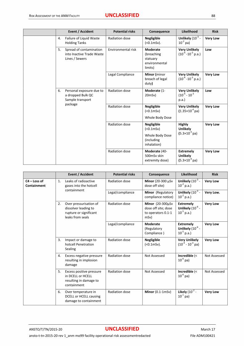
RISK ASSESSMENT OF THE ANM FACILITY UNCLASSIFIED 88
ANSTO/T/TN/2015‐20 UNCLASSIFIED March 17
ansto‐t‐tn‐2015‐20 rev 1_anm mo99 facility operational risk assessmentredacted File ADM100421
Event / Accident Potential risks Consequence Likelihood Risk
4. Failure of Liquid Waste Holding Tanks
Radiation dose Negligible (<0.1mSv).
Unlikely (10‐3 ‐ 10‐2 pa)
Very Low
5. Spread of contamination into Inactive Trade Waste Lines / Sewers
Environmental risk Moderate (breaching statuary environmental limits)
Very Unlikely (10‐4 ‐10‐3 p.a.)
Low
Legal Compliance Minor (minor breach of legal duty)
Very Unlikely (10‐4 ‐10‐3 p.a.)
Very Low
6. Personal exposure due to a dropped Bulk QC Sample transport package
Radiation dose Moderate (1‐20mSv)
Very Unlikely (10
‐4 ‐ 10‐3 p.a.)
Low
Radiation dose Negligible (<0.1mSv)
Whole Body Dose
Very Unlikely (1.35×10
‐4 pa) Very Low
Radiation dose Negligible (<0.1mSv)
Whole Body Dose (including inhalation)
Highly Unlikely (5.3×10‐5 pa)
Very Low
Radiation dose Moderate (40‐500mSv skin extremity dose)
Extremely Unlikely (5.3×10
‐6 pa)
Very Low
Event / Accident Potential risks Consequence Likelihood Risk
C4 – Loss of Containment
1. Leaks of radioactive gases into the hotcell containment
Radiation dose Minor (20‐300 µSv dose off site)
Unlikely (10‐3 ‐
10‐2 p.a.) Very Low
Legal/compliance Minor (Regulatory compliance notice)
Unlikely (10‐3 ‐ 10
‐2 p.a.) Very Low.
2. Over pressurisation of dissolver leading to rupture or significant leaks from seals
Radiation dose Minor (20‐300µSv dose off site; dose to operators 0.1‐1 mSv)
Extremely Unlikely (10
‐6 ‐ 10‐5 p.a.)
Very Low
Legal/compliance Moderate (Regulatory Compliance )
Extremely Unlikely (10
‐6 ‐ 10‐5 p.a.)
Very Low
3. Impact or damage to hotcell Penetration Sealing
Radiation dose Negligible (<0.1mSv).
Very Unlikely (10‐4 ‐ 10‐3 pa)
Very Low
4. Excess negative pressure resulting in implosion damage
Radiation dose Not Assessed Incredible (< 10‐6 pa)
Not Assessed
5. Excess positive pressure in DCELL or HCELL resulting in damage to containment
Radiation dose Not Assessed Incredible (< 10‐6 pa)
Not Assessed
6. Over temperature in DCELL or HCELL causing damage to containment
Radiation dose Minor (0.1‐1mSv) Likely (10‐2 ‐ 10‐1 pa)
Very Low

RISK ASSESSMENT OF THE ANM FACILITY UNCLASSIFIED 89
ANSTO/T/TN/2015‐20 UNCLASSIFIED March 17
ansto‐t‐tn‐2015‐20 rev 1_anm mo99 facility operational risk assessmentredacted File ADM100421
Event / Accident Potential risks Consequence Likelihood Risk
7. Loss of hotcell containment due to Spurious operation of vacuum break devices
Radiation dose Negligible (<0.1mSv)
Likely (10‐2 ‐ 10‐1 pa)
Low
8. Overpressure of Liquid Waste Decay Tanks
Radiation dose Negligible (<0.1mSv)
Extremely Unlikely (10‐6 ‐ 10‐5 pa)
Very Low
Operations/ Plant Damage
Moderate (loss of production <1 month / report to regulator).
Extremely Unlikely (10‐6 ‐ 10‐5 pa)
Very Low
9. Loss of containment in the gas transfer lines
Radiation dose (public)
Negligible (<20µSv dose to members of the public)
Unlikely (10‐3 ‐ 10‐2 p.a.)
Very Low
Radiation dose Negligible (dose to personnel on‐site < 0.1mSv)
Unlikely (10‐3 ‐ 10
‐2 p.a.) Very Low
10. Impact or damage to Airlock leading to loss of containment
Radiation dose Negligible (<0.1mSv)
Unlikely (10‐3 ‐ 10‐2 pa)
Very Low
Event / Accident Potential risks Consequence Likelihood Risk
C5 ‐ Failure of the AVS System
1. Red primary exhaust ventilation failure prior to a Mo‐99 production run
Radiation dose Negligible (<0.1mSv dose)
Likely (10‐2 ‐
10‐1 p.a.) Very Low
Radiation dose ‐(failing to evacuate)
Negligible (<0.1mSv dose)
Very Unlikely (10‐4 ‐ 10‐3 p.a.)
Very Low
2. Red primary exhaust ventilation failure during a normal Mo‐99 production run
Radiation dose Negligible (<0.1mSv dose)
Likely (10‐2 ‐
10‐1 p.a.) Very Low
Radiation dose ‐(failing to evacuate)
Negligible (<0.1mSv dose)
Very Unlikely (10‐4 ‐ 10‐3 p.a.)
Very Low
3. Red primary exhaust ventilation failure during an accidental release of radioactivity into any of the production hotcells
Radiation dose Moderate (1‐20mSv dose)
Highly Unlikely (10
‐5 ‐ 10‐4 p.a.)
Very Low
Radiation dose ‐(failing to evacuate)
Major (20‐100mSv dose)
Incredible (< 10
‐6 p.a.) Not Assessed
4. Red primary exhaust ventilation failure during periods of maintenance access to hotcells
Radiation dose Negligible (<0.1mSV dose)
Unlikely (10‐3 ‐ 10
‐2p.a.) Very Low
5. Accidental release of above‐normal radioactivity by selecting the wrong gas tank for release
Radiation dose (public)
Minor (dose to members of the public in the range 20‐300 µSv).
Likely (10‐2 ‐ 10
‐1 p.a.) Low
Radiation dose Negligible (dose to personnel on‐site < 0.1mSv)
Likely (10‐2 ‐ 10‐1 p.a.)
Very Low
6. Airborne contamination in the building resulting from backflows from the stack.
Radiation dose Negligible (<0.1mSv dose to personnel).
Very Unlikely (10
‐4 ‐ 10‐3 p.a.)
Very Low

RISK ASSESSMENT OF THE ANM FACILITY UNCLASSIFIED 90
ANSTO/T/TN/2015‐20 UNCLASSIFIED March 17
ansto‐t‐tn‐2015‐20 rev 1_anm mo99 facility operational risk assessmentredacted File ADM100421
Event / Accident Potential risks Consequence Likelihood Risk
7. Airborne contamination monitoring in the front of cell area following a process accident.
Radiation dose Not Assessed Incredible (< 10‐6 p.a.)
Not Assessed
8. Airborne contamination monitoring in the basement area following a leak of gas tanks or AVS ducts
Radiation dose Moderate (1‐20mSv dose)
Highly Unlikely (10‐5 ‐ 10‐4 p.a.)
Very Low
Event / Accident Potential risks Consequence Likelihood Risk
C6 ‐ Flask operations
1. Spurious opening of top shield door or gate valve due to control failure in DCELL without a flask in place
Radiation dose (opening shield door)
Moderate (1‐20mSv dose)
Very Unlikely (10‐4 ‐ 10‐3 p.a.)
Low
Radiation dose (opening gate valve)
Negligible (<0.1mSv inhalation dose )
Very Unlikely (10‐4 ‐ 10‐3 p.a.)
Very Low
2. Accidental opening of top shield door or gate valve in DCELL without a flask in place
Radiation dose (opening shield door)
Moderate (1‐20mSv dose)
Very Unlikely (10‐4 ‐ 10‐3 p.a.)
Low
Radiation dose (opening gate valve)
Negligible (<0.1mSv inhalation dose )
Very Unlikely (10
‐4 ‐ 10‐3 p.a.)
Very Low
3. Accidental removal of the flask from the top of DCELL without first closing the shield door and the gate valve
Radiation dose (without closing shield door)
Moderate (1‐20mSv dose)
Unlikely (10‐3
‐ 10‐2 p.a.) Low
Radiation dose (without closing gate valve)
Negligible (<0.1mSv inhalation dose )
Unlikely (10‐3
‐ 10‐2 p.a.)
Very Low
4. Accidental opening of top shield door or gate valve in HCELL
Radiation dose (without closing shield door)
Negligible (<0.1mSv dose)
Very Unlikely (10
‐4 ‐ 10‐3 p.a.)
Very Low
Radiation dose (without closing gate valve)
Negligible (<0.1mSv inhalation dose )
Very Unlikely (10
‐4 ‐ 10‐3 p.a.)
Very Low
5. Spurious opening of the top shield door or gate valve in the ILSW cell without a flask in place
Radiation dose (without closing shield door)
Minor (0.1‐1mSv dose)
Very Unlikely (10‐4 ‐ 10‐3 p.a.)
Very Low
Radiation dose (without closing gate valve)
Negligible (<0.1mSv inhalation dose )
Very Unlikely (10‐4 ‐ 10‐3 p.a.)
Very Low
6. Accidental opening of top shield door or gate valve in the ILSW cell without a flask in place
Radiation dose (without closing shield door)
Minor (0.1‐1mSv dose)
Highly Unlikely (10‐5 ‐ 10‐4 p.a.
Very Low
Radiation dose (without closing gate valve)
Negligible (<0.1mSv inhalation dose )
Highly Unlikely (10
‐5 ‐ 10‐4 p.a.)
Very Low
7. Accidental removal of the flask from the top of ILSW cell without first closing
Radiation dose (without closing shield door)
Minor (0.1‐1mSv dose)
Unlikely (10‐3 ‐ 10
‐2 p.a.) Very Low

RISK ASSESSMENT OF THE ANM FACILITY UNCLASSIFIED 91
ANSTO/T/TN/2015‐20 UNCLASSIFIED March 17
ansto‐t‐tn‐2015‐20 rev 1_anm mo99 facility operational risk assessmentredacted File ADM100421
Event / Accident Potential risks Consequence Likelihood Risk
the shield door and the gate valve
Radiation dose (without closing gate valve)
Negligible (<0.1mSv inhalation dose )
Unlikely (10‐3 ‐ 10‐2 p.a.)
Very Low
8. Accidental removal of the flask from the top of ILSW cell without first closing the flask ball valve
Radiation dose Minor (0.1‐1mSv dose)
Unlikely (10‐3 ‐ 10‐2 p.a.)
Very Low
9. Misalignment or placing wrong flask on top of ILSW cell
Radiation dose Minor (0.1‐1mSv dose)
Very Likely (0.1‐1 p.a.)
Low
10. Accidental opening of the PMP shield door of a hotcell using the PTS without a PADIRAC cask
Radiation dose Not Assessed Incredible (<10‐6 p.a.)
Not Assessed
11. Accidental Opening the PADIRAC cask door with radioactive items inside
Radiation dose ‐ PADIRAC Cask opened in error
Moderate (1‐20mSv dose)
Extremely Unlikely (10‐6 – 10‐5 p.a.)
Very Low
Radiation dose ‐ Operator exposes to radioactivity when loading non‐radioactive items
Moderate (1‐20mSv dose)
Very Unlikely (10‐4 – 10‐3 p.a.)
Low
12. Accidental opening of the DPTE door of a hotcell without a DPTE container pushed against the door opening
Radiation dose Negligible (<0.1mSv inhalation dose)
Likely (10‐2 ‐
10‐1 p.a.) Low
13. Accidental closing the PMP Door or PADIRAC Cask door on DPTE container
Operations
Moderate (limited damage to equipment)
Very Unlikely (10
‐4 ‐ 10‐3 p.a.)
Low
Radiation dose Minor (0.1 ‐1mSv) Very Unlikely (10‐4 ‐ 10‐3 p.a.)
Very Low
14. Accidental opening the shield door of the B(U) port when there is high activity inside the packaging cell.
Radiation dose Minor (0.1‐1mSv) Very Unlikely (10‐4 ‐ 10‐3 p.a.)
Very Low
15. Lowering the B(U) IC trolley when there is high activity inside the packaging cell
Radiation dose Minor (0.1‐1mSv) Likely (10‐2 ‐ 10‐1 p.a.)
Low
16. High activity source passed through to the Packaging cell when the shield door is open
Radiation dose Minor (1 ‐ 20mSv) Likely (10‐2 ‐ 10‐1 p.a.)
Low
17. Dropping Mo‐99 product container through the B(U) port door without a B(U) IC docked in the B(U) port of the packaging cell
Radiation dose Moderate (1 ‐ 20mSv)
Highly Unlikely (10‐5 ‐ 10
‐4 p.a.)
Very Low
Major (20 ‐ 100mSv) Extremely Unlikely (10‐6 ‐ 10
‐5 p.a.)
Low

RISK ASSESSMENT OF THE ANM FACILITY UNCLASSIFIED 92
ANSTO/T/TN/2015‐20 UNCLASSIFIED March 17
ansto‐t‐tn‐2015‐20 rev 1_anm mo99 facility operational risk assessmentredacted File ADM100421
Event / Accident Potential risks Consequence Likelihood Risk
18. B(U) IC loaded with an MPB/IPC is lowered without the lid in place
Radiation dose Minor (0.1‐1mSv) Likely (10‐2 ‐ 10‐1 p.a.)
Low
Event / Accident Potential risks Consequence Likelihood Risk
C7 – Unauthorised entry of operator to a High radiation / contamination area
1. Unauthorised entry to basement area, ground floor or mezzanine floor area
Radiation dose Minor (0.1‐1mSv dose)
Very Unlikely (10‐4 ‐ 10‐3 p.a.)
Very Low
2. Operator enters the liquid waste sampling cell when there is radioactivity inside
Radiation dose Minor (0.1‐1mSv dose)
Unlikely (10‐3 ‐ 10
‐2 p.a.) Very Low
3. Operator enters liquid waste valve room without adequate flushing of the waste pipes
Radiation dose Minor (0.1‐1mSv dose)
Likely (10‐2 ‐ 10‐1 p.a.)
Low
4. Operator opens the maintenance access door of the packaging cell without first ensuring that there is no significant radioactivity inside the cell.
Radiation dose (Worst case)
Major (20‐100mSv dose)
Highly Unlikely (10
‐5 ‐ 10
‐4 p.a.)
Low
Radiation dose (majority of cases)
Moderate (1‐20mSv dose)
Highly Unlikely (10
‐5 ‐ 10
‐4 p.a.)
Very Low
Event / Accident Potential risks Consequence Likelihood Risk
C8 ‐ Fire in the Facility
1. Fire in the loading bay WHS ‐ Physical injury
Insignificant (no injuries)
Extremely Unlikely (10‐6 ‐ 10
‐5 p.a.)
Very Low
2. Fire in the Cell Face Area WHS ‐ Physical injury
Insignificant (no injuries)
Very Unlikely (10‐4 ‐ 10‐3 p.a.)
Very Low
3. Fire in the Active Maintenance Area
WHS ‐ Physical injury
Insignificant (no injuries)
Very Unlikely (10‐4 ‐ 10‐3 p.a.)
Very Low
4. Fire in the Ventilation Plant Room
Radiation dose ‐ Public
Minor (20µSv to 300 µSv off‐ site dose to members of the public).
Very Unlikely (10‐4 ‐ 10‐3p.a.)
Very Low
Radiation dose Moderate (1‐20mSv dose to personnel on site
Very Unlikely (10‐4 ‐ 10‐3p.a.)
Low
5. Fire in the hotcell Radiation dose ‐ Public
Minor (20µSv to 300 µSv off‐ site dose to members of the public).
Highly Unlikely (10‐5 ‐ 10‐4p.a.)
Very Low
Radiation dose Moderate (1‐20mSv dose to personnel on site
Highly Unlikely (10
‐5 ‐ 10‐4p.a.)
Very Low
6. Fire in the Carbon Column Radiation dose ‐ Public
Minor (20µSv to 300 µSv off site dose to members of the public).
Highly Unlikely (10‐5 ‐ 10
‐4p.a.)
Very Low

RISK ASSESSMENT OF THE ANM FACILITY UNCLASSIFIED 93
ANSTO/T/TN/2015‐20 UNCLASSIFIED March 17
ansto‐t‐tn‐2015‐20 rev 1_anm mo99 facility operational risk assessmentredacted File ADM100421
Event / Accident Potential risks Consequence Likelihood Risk
Radiation dose Moderate (1‐20mSv dose to personnel on site
Highly Unlikely (10‐5 ‐ 10‐4p.a.)
Very Low
7. Fire in the Carbon Filter bank
Radiation dose ‐ Public
Minor (20µSv to 300µSv off site dose to members of the public).
Highly Unlikely (10‐5 ‐ 10‐4p.a.)
Very Low
Radiation dose Moderate (1‐20mSv dose to personnel on site
Highly Unlikely (10‐5 ‐ 10‐4p.a.)
Very Low
8. Fire in the QC Laboratory WHS ‐ Physical injury
insignificant (no injuries)
Very Unlikely (10‐4 ‐ 10‐3 p.a.)
Very Low
9. Fire/ explosion in the Gas Cylinder Store –
Rocketing Cylinder (Unloading)
WHS ‐ Physical injury
moderate (Injuries requiring medical attention)
Very Unlikely (10
‐4 ‐ 10‐3 p.a.)
Low
Risk of Explosion (Storage) WHS ‐ Physical injury
moderate (Injuries requiring medical attention)
Highly Unlikely (10‐5 ‐ 10
‐4 p.a.)
Low
Rocketing Cylinder (Transport)
WHS ‐ Physical injury
moderate (Injuries requiring medical attention)
Highly Unlikely (10‐5 ‐ 10‐4 p.a.)
Low
Ignition WHS ‐ Physical injury
Major (Serious Injury)
Very Unlikely (10
‐4 ‐ 10‐3 p.a.)
Medium
Oxygen Depletion WHS ‐ Physical injury
Negligible (Injuries requiring medical attention)
Very Unlikely (10
‐4 ‐ 10‐3 p.a.)
Low
10. Fire or bushfire smoke, embers or heat causes injury
WHS ‐ Physical injury
Minor (0.1 – 1 mSv).
Very Likely (0.1 to 1 p.a.)
Low
Event / Accident Potential risks Consequence Likelihood Risk
C9 ‐ Hydrogen fire or explosion
1. Hydrogen fire or explosion inside hotcell containment
Radiation dose
Legal/compliance
WHS ‐ Physical injury
Not Assessed
Incredible (<10‐6 p.a.)
Not Assessed
2. Hydrogen fire or explosion in the AVS exhaust ducts
An explosive mix of hydrogen and air in the AVS exhaust ducts due to hydrogen conversion failure
Radiation dose Negligible (dose to operators <0.1mSv)
Highly Unlikely (<10
‐5 ‐10‐4p.a.)
Very Low
Legal/ Compliance Moderate (Major administrative complaint )
Highly Unlikely (<10‐5 ‐10‐4p.a.)
Very Low

RISK ASSESSMENT OF THE ANM FACILITY UNCLASSIFIED 94
ANSTO/T/TN/2015‐20 UNCLASSIFIED March 17
ansto‐t‐tn‐2015‐20 rev 1_anm mo99 facility operational risk assessmentredacted File ADM100421
Event / Accident Potential risks Consequence Likelihood Risk
Entry of air into process containment during dissolution and possible explosion inside process containment
Radiation dose
Legal/ Compliance
Radiation dose ‐ public
Not Assessed
Incredible (<10
‐6 p.a.)
Not Assessed
Event / Accident Potential risks Consequence Likelihood Risk
C10 ‐ Damage to Plant equipment as a result of a Seismic event
1. Damage to process tanks or piping due to a seismic event
Radiation dose ‐ Public
Minor (20‐300µSv dose off site)
Highly Unlikely (10‐5 ‐ 10‐4 p.a.)
Very Low
Radiation dose Major (20‐100mSv dose to operators).
Highly Unlikely (10‐5 ‐ 10
‐4 p.a.)
Low
Legal/ Compliance Moderate( Major administrative complaint )
Highly Unlikely (10‐5 ‐ 10‐4 p.a.)
Low
2. Seismic Failure of Decay Tanks
Radiation dose Moderate (1‐20mSv).
Highly Unlikely (10‐5 ‐ 10‐4 pa)
Very Low
Environmental Major (Medium term damage confined to buffer zone).
Highly Unlikely (10
‐5 ‐ 10‐4 pa)
Low
3. Seismic Failure of the Liquid Waste Holding Tanks
Radiation dose Moderate (1‐20mSv).
Highly Unlikely (10
‐5 ‐ 10‐4 pa)
Very Low
Environmental Major (Medium term damage confined to buffer zone).
Highly Unlikely (10
‐5 ‐ 10
‐4 pa)
Low
Event / Accident Potential risks Consequence Likelihood Risk
C11 ‐ Criticality 1. Criticality incident Radiation dose Not Assessed Incredible (<10
‐6 p.a.) Not Assessed
Event / Accident Potential risks Consequence Likelihood Risk
C12 – Industrial Hazards
1. Accidental contact with electrical terminals
WHS ‐ Physical injury Severe (Fatality or permanent injury )
Highly Unlikely (10‐5‐10‐4 p.a.)
Medium
2. Worker falling during maintenance and operations
WHS ‐ Physical injury Major (Long term injury but recovery probable )
Very Unlikely (10‐4‐10‐3 p.a.)
Medium
3. Injury Due to Slip, Trip or Fall in general areas
WHS ‐ Physical injury Moderate (lost time injury)
Unlikely (10‐3 ‐ 10‐2 pa)
Low
4. Manual handling accident WHS ‐ Physical injury Moderate (Medical attention or several lost time days)
Unlikely (10‐3 ‐ 10
‐2 pa) Low

RISK ASSESSMENT OF THE ANM FACILITY UNCLASSIFIED 95
ANSTO/T/TN/2015‐20 UNCLASSIFIED March 17
ansto‐t‐tn‐2015‐20 rev 1_anm mo99 facility operational risk assessmentredacted File ADM100421
APPENDIXC‐FAILURESDURINGPROCESSOPERATIONSThe following accidents with initiation due to process failure were postulated. The risks associated with the scenarios have been assessed as per the tables in the Guidance on the Conduct of a Risk Study (AG 2395)
C.1 AccidentduringOnSitetransport
C.1.1 TransportaccidentinvolvingthetransferoftargetsfromOPALtotheANMFacility
The transport of targets from OPAL to the ANM Facility is conducted according to Work Instruction ARI/ 09 07 02 0 D.wk1 (Jones et al, 2007).
The premature removal of targets from the OPAL service pool (SPO) may cause them to overheat and blister/melt. However, the Service Pool Elevator (SPE) that raises the Bulk Irradiation Rig (BIR) containing irradiated targets from the SPO into the Transfer hotcell (THC) has a radiation based interlock called the Molybdenum Safety Device (MSD). If, however, the targets were to be removed prematurely and either the safety interlocks were to fail, or the targets have not been correctly loaded into the BIR as per OPAL OLC 3.9.4 (ANSTO, 2008) there is a potential for a fission product release. Such a release would most likely occur in the THC upon removal of the target plates from the pool or during handling of the targets prior to transfer to the transport flask. A health physics clearance is required prior to transport. Provided the targets are successfully transported to the transport flask, fuel blistering/melting during transport due to premature removal of the targets from the pool is not considered to be credible.
Calculations and tests have shown that in both normal and accident scenarios the target plates will not melt during transport (Wassink, 2007, Wassink 2008) provided they are sufficiently decayed prior to removal. In the worst case scenario analysed, two full plate holders containing test plates, were placed horizontally inside a sealed and submerged pipe, and remained below the safety limit of 400°C.
There is a potential for a diesel fire to occur as a result of an accident. However, such fires only occur rarely in road traffic accidents involving a truck and even less frequently for low speed accidents. The flask is classified as being a hazardous load and as such during transport there is an on‐site speed limit of 10 km/h (Jones et al, 2007). In addition, the on‐site emergency response is likely to quickly extinguish any such fire before it is capable of significantly affecting the flask or its contents.
The transport flask is very robust in construction (mild steel casing filled with lead and weighing approximately 7.5 tonnes), and is considered to be capable of withstanding a significant impact. In addition, the transport truck should be able to absorb much of the impact energy associated with most transport accidents, although there is a potential for the truck to tip over and the flask to subsequently fall off. However, during transport the flask is secured by four mild steel chain “tie‐downs” and movement of the flask should be limited. The possibility of an accident that results in the truck rolling over the flask is not considered to be credible given the low speed of the truck.
During transport, the aluminium‐clad target plates are secured inside target transport holders. These holders are in turn placed into a carrier. The carrier is then lifted into the transport flask before being secured with a locking pin. Furthermore, the rotating door located at the bottom of the flask is secured during transport.
It is deemed incredible (Penny, 2009) for the flask to be damaged in such a way that the shielding is partially compromised and shine paths between the target plates and the outside of the flask are created. Because the accident is considered incredible, the event is not considered any further.
C.1.2 TransportaccidentfromANMFacilitytoBuilding23
The B(U) transfer container is very robust (mild steel casing filled with lead and weighing approximately 1.2 tonnes) and thus capable of withstanding a significant impact. The B(U) transfer container is classified as being a hazardous load and as such during transport there is an on‐site to a speed limit of 10 km/h (Jones et al, 2007). The truck should be able to absorb much of the impact energy associated with most transport accidents although there is the potential for the truck to tip over and the container to fall off. However, the container is secured by two mild steel chain “tie‐downs” that effectively prevent this occurrence. Considering the limited speeds involved it is not considered credible for an accident to result in the truck turning over onto the flask.
There is a potential for a diesel fire to occur as a result of an accident. However, such fires only occur rarely in road traffic accidents involving a truck and even less frequently for low speed accidents. In addition, the on‐

RISK ASSESSMENT OF THE ANM FACILITY UNCLASSIFIED 96
ANSTO/T/TN/2015‐20 UNCLASSIFIED March 17
ansto‐t‐tn‐2015‐20 rev 1_anm mo99 facility operational risk assessmentredacted File ADM100421
site emergency response is likely to quickly extinguish any such fire before it is capable of significantly affecting the container or its contents
The product is 50 mL of sodium molybdate solution (with up to 33 TBq of activity) contained in a sealed and capped vial. The vial is located inside a sealed transfer canister that is located within a transfer bucket. During transport the bucket is suspended inside the B(U) transfer container by a lifting cable and secured into place by a locking pin. In addition, the rotating door in the bottom of the container is secured shut. Finally, an aluminium sheet is secured over the base as part of the contamination control measures. An accident of sufficient severity to remove the canister from the container is not considered credible.
It was previously deemed credible for the container to be damaged in such a way that the shielding is partially compromised and shine paths between the transport canister and the outside of the container are created. This would result in localised beams of radiation exiting the container. The likelihood of this scenario has been reassessed and has now been assessed as being incredible (Penny, 2009). Because the accident is considered incredible, the event is not considered any further.
C.2 DroppedloadwithintheFacility
C.2.1 Droppingthetransportflaskintheloadingbay
The transport flask is very robust in construction (mild steel casing filled with lead and weighing approximately 7.5 tonnes).
The rear of the Cell crane used for the flask’s movements will be Dangerous Goods rated (12 tonne) with dual ropes and over speed emergency brakes, so the weight of the flask is within its limits. This crane will routinely lift the following:
Flasks containing active materials (target flask, SUF flask or retrievable waste flask). Because these are bottom loading they are lifted to a height above the hotcells;
The PADIRAC cask containing active materials to a minimal height above the floor; and
Other loads as required.
If there is a load drop of a flask, it is also Extremely Unlikely (10‐6 ‐ 10‐5 pa) to lead to an operator receiving a significant severe dose (100 – 1000 mSv)* because:
The active materials are solids held in purpose‐designed containers that are unlikely to release the contents during a drop, and
The flasks are massive and the shielding is unlikely to be made significantly less effective by a drop. i.e. the flask is likely to be capable of withstanding a drop from normal operating heights without a loss of integrity.
Although every effort will be undertaken to minimise the lift height, the flasks need to be lifted above the height of the hotcells, there is the potential for a load drop from considerable height.
The risk of an injury due to a crane load drop during flask or other high lift operations is assessed as having a consequence of severe (potential fatality) with a corresponding likelihood of Extremely Unlikely (10‐6 ‐ 10‐5 pa).
The risk associated with the scenario described above has been assessed as follows:
Consequence Likelihood Risk
Severe (potential fatality) Extremely Unlikely(10‐6 ‐ 10‐5 pa)
Low
Severe (100 – 1000 mSv) Extremely Unlikely(10‐6 ‐ 10‐5 pa)
Low
*this is based on flask containing irradiated targets. The consequence from a flask containing SUF cups will be an order of magnitude less.
C.2.2 Droppingatargetplatesoutofthebottomofthetransportflask
The aluminium‐clad target plates are secured inside target transport holders, which are in turn secured into a transport carrier that is lifted and secured with a locking pin within the flask. The transport carrier has been

RISK ASSESSMENT OF THE ANM FACILITY UNCLASSIFIED 97
ANSTO/T/TN/2015‐20 UNCLASSIFIED March 17
ansto‐t‐tn‐2015‐20 rev 1_anm mo99 facility operational risk assessmentredacted File ADM100421
designed with top and bottom retaining plates to accommodate the safe and secure transport of three transport holders within the 7.5 tonne flask.
These operations are undertaken at OPAL prior to transport (as described in Section 5.1) , and as a fault would require the flask door to be left open during the lift (an operator error by OPAL Plant operators) and the locking pin mechanism holding the carrier within the flask to fail.
Therefore, the potential for dropping a transport carrier containing target plates out of the bottom of the transport flask when lifted off the truck is not considered credible. Inadvertent opening is also not considered credible also due to the flask door’s mechanical design. Because the accident is considered incredible, the event is not considered any further.
C.2.3 Droppingthetransportflaskontothecellroof
This accident is considered to be bounded by the dropping the transport flask in the loading bay with respect to the potential for damaging the flask itself. This is on the basis that the heights involved are significantly less than those associated with the drop in the loading bay. Therefore, as discussed within Section C.2.1 If there is a load drop of a flask, it is Extremely Unlikely (10‐6 ‐ 10‐5 pa) to lead to an operator receiving a significant dose severe (100 – 1000 mSv).
With respect to the potential for damage to the cell roof, the operating procedure (Jones et al, 2007) suggests that the height of the flask above the cell roof is maintained as low as reasonably practicable (500mm). A drop from such a height is unlikely to result in any significant damage to the roughly 1 m thick concrete cell roof, particularly sufficient damage to result in a release of activity. The impact withstand of the hotcell has been confirmed by engineering assessments (AECOM, 2015b). The hotcell shielding structure is separate and independent to the containment structure, and any damage to shielding would not impact the containment. The consequence may be a reduced shine path through the shielding, but not a failure of the shielding.
In addition, there are no “vulnerable” items of plant on the cell roof that could be damaged in such a way as to result in an increased leakage rate from the hotcells and thus, a potential release of activity.
The more significant situation would be dropping the flask on an operator physical injury, although the likelihood of this is small, as operators stand a safe distance away, the flask only moves slowly, and is bottom‐heavy, so it will not easily topple.
The risk of an injury due to a crane load drop during flask or other high lift operations is assessed as having a consequence of severe (potential fatality) with a corresponding likelihood of Extremely Unlikely (10‐6 ‐ 10‐5 pa). as per the fault assessed within Section C.2.1.
The risk associated with the scenario described above has been assessed as follows:
Consequence Likelihood Risk
Severe (potential fatality) Extremely Unlikely(10‐6 ‐ 10‐5 pa)
Low
Severe (100 – 1000 mSv) Extremely Unlikely(10‐6 ‐ 10‐5 pa)
Low
C.2.4 DroppingaB(U)container
The BU container which is an approved and licensed containers for Mo‐99 transportation are used for the bulk Mo‐99 product to be dispatched, is substantiated to a drop of 9.0m (to maintain its shielding and containment properties). It consists of the following components.
Molybdenum product bottle (MPB)
Inner Product Container (IPC)
Depleted Uranium (DU) inner container
Stainless steel Outer container referred to as the B(U) container.
The radioactive material in its most vulnerable part of the lifting process has at least 3 layers of barriers, when lifted from the Dispensing hotcells onto the conveyor system in the dispatch room, using JCR‐02.

RISK ASSESSMENT OF THE ANM FACILITY UNCLASSIFIED 98
ANSTO/T/TN/2015‐20 UNCLASSIFIED March 17
ansto‐t‐tn‐2015‐20 rev 1_anm mo99 facility operational risk assessmentredacted File ADM100421
It is possible that the BU container with the maximum allowable inventory of 56TBq could be dropped during this lift sometime over the life of the plant.
However the potential for crane load drops in ANM will be minimised due to the following measures.
Certified cranes conforming to AS 1418.1 DGR rating
Accredited crane operators and dogmen.
Regular inspection, maintenance and testing.
Even if the BU container with Mo‐99 product is dropped, the likelihood, of any damage to the container that could cause damage to the shielding exposing a worker to the source is considered to be Extremely Unlikely (frequency in the range of 10‐6‐10‐5 p.a.), since the container is strong enough to take the impact of the drop of 9.0m, and the lift undertaken is only 1.5m high.
In addition, the components of the BU container, i.e. the DU, IPC and MPB are all tightly sealed packages, therefore the risk of a release of respirable activity from the 3 sealed containers is considered to be minimal. The worker is estimated to evacuate immediately on response to dropped load, thereby increasing their distance from the source and minimising their exposure time. The indirect radiation exposure is considered to be negligible (<0.1mSv).
The risk associated with the scenario described above has been assessed as follows:
Consequence Likelihood Risk
Negligible (<0.1mSv). Extremely Unlikely (10‐6 ‐ 10‐5 pa) Very Low
C.2.5 Droppingorimpactingaloadontoservicesorductwork
There is the potential to impact systems and services when undertaking day to day, or maintenance activities.
For example the helium station which is situated on the corridor which lead to the front of Cell could be hit by the B(U) trolley or manipulators maintenance trolley. This could cause operational problems and would require the repair or replacement of the helium testing station (minor, slight delay to operations), but will not create a safety hazard.
Such movement will be closely controlled by, although there is adequate space around the facility and corridors to avoid such collision. Exclusion zones around the helium testing station, as well any exposed pipework around the facilities will be in place to reduce the likelihood of such an impact further.
Recommendation:
R1: To avoid impacting a load onto services or ductwork, movement within facility must be closely controlled and there must be exclusion zones around exposed pipework and vulnerable systems.
Exposed pipework across the facility are protected by steel angles around the base of the pipe.
Mechanical lifting equipment such as monorails includes end stops to limit their movement, whilst jib cranes include impact limiters on nearby walls to limit their swing.
These protective measures as well as the trained operators undertaking the task insure the likelihood of impacting vulnerable systems or services remaining relatively low (Very Unlikely, frequency in the region of 10‐4‐10‐3 p.a.).
The risk associated with the scenario described above has been assessed as follows:
Consequence Likelihood Risk
Minor (slight operational delay) Very Unlikely (10‐4 ‐ 10‐3 p.a.) Very Low
C.2.6 DroppedHEPAFilter
The System is equipped with primary and secondary HEPA filters. The primary HEPA filters are changed on high dP to ensure the extract route does not become blocked.
The filters are located within safe‐change filter housings; therefore they are maintained within bagged containment throughout the filter change operation and then placed in a transport container for export from

RISK ASSESSMENT OF THE ANM FACILITY UNCLASSIFIED 99
ANSTO/T/TN/2015‐20 UNCLASSIFIED March 17
ansto‐t‐tn‐2015‐20 rev 1_anm mo99 facility operational risk assessmentredacted File ADM100421
the Facility. This means no contamination will be resuspended to the local atmosphere during the task unless an error occurs.
The most likely error leading to a puncture of the filter bag containment and release of activity is considered to be a dropped ‘dirty’ filter during the task. The impact from dropping the filter could lead to puncturing of the bag and re‐suspension of particulate activity on the filter. This resuspended activity could lead to an increased inhalation dose uptake to the worker performing the task moderate (1‐20mSv).
It is considered Very Unlikely (frequency in the range of 10‐4 ‐ 10‐3 p.a.) that such a scenario could happen. The task is performed by experienced maintenance engineers to approved working procedures, therefore the hazards involved in the task and the actions in the task itself are well understood by the workers. Health Physics will be present during the filter change task and local radiological monitoring will provide an indication of any re‐suspension of activity and deviation from the safe operating envelope.
Further defence in depth is provided via the provision of Radiological PPE (e.g. a respirator), if required, for the personnel involved in the filter change task. Should any activity be resuspended by this fault then the inhalation dose uptake to personnel will be minimised by the use of Radiological PPE.
Recommendation:
R2: Personnel involved in filter change operations should wear respirators to minimise the inhalation dose uptake should activity on the filter is resuspended.
The risk associated with the scenario described above has been assessed as follows:
Consequence Likelihood Risk
Moderate (1‐20mSv) Very Unlikely (10‐4 ‐ 10‐3 p.a.) Low
C.3 SpillsleadingtoSpreadofContamination
C.3.1 Spillofradioactiveliquidintohotcellcontainment
Spill of radioactive liquid into the hotcell from process containment could occur due to the following failures.
Leaks in tanks, pipes, and valves.
Human error in the fitting of SUF cup.
Valves and pipes of process containment use swaged connections. Tanks and pipes undergo routine pressure and vacuum tests prior to each dissolution run. These are designed for much higher pressures than are normally experienced in operating conditions.
Human error in the fitting of SUF cups during filtration is possible but any leaks are visible and an operator can take remedial action to tighten the filter and stop the leak. The likelihood is considered Unlikely (frequency in the range of 10‐3 ‐ 10‐2 p.a.).
Any spill is contained within the hotcell containment. The solute of the dissolution process is not volatile and therefore any airborne releases are considered not significant negligible (<20 µSv dose off site). Nevertheless, this event constitutes a minor (Regulatory compliance notice) consequence from a Legal/Compliance aspect. The liquid spills within the hotcell can be cleaned up using manipulators without any radiation exposure to personnel. Resulting radioactive waste can be transferred to Intermediate Level Solid Waste (ILSW) cell via PADIRAC movements and to liquid waste tanks by appropriate vacuum transfers.
The risk of this scenario is assessed as follows.
Consequence Likelihood Risk
Negligible (<20 µSv dose off site) Unlikely (10‐3 ‐ 10‐2 p.a.) Very Low
Minor (Regulatory compliance notice)
Unlikely (10‐3 ‐ 10‐2 p.a.) Very Low

RISK ASSESSMENT OF THE ANM FACILITY UNCLASSIFIED 100
ANSTO/T/TN/2015‐20 UNCLASSIFIED March 17
ansto‐t‐tn‐2015‐20 rev 1_anm mo99 facility operational risk assessmentredacted File ADM100421
C.3.2 Spillageofotherliquidswithinoroutsidethecell
The maximum volume of other liquids that may be spilt in the cell is the water contained within the recirculating cooling water system. Although it is anticipated that the majority of this water would be captured within the cell in the event of a spillage, it is assumed that it would all be routed to one of the liquid waste delay tanks located in the basement of the Facility. The concern is that this water could flush activity (including potentially “hot” particles) into these delay tanks. The tanks are checked for activity before being discharged so that any activity that may get into them should be detected and appropriate measures taken to ensure that any release is within the appropriate limits.
Chemicals are dispensed in the laboratory into the correct volumes for the process. Once the solutions for a run have been dispensed they are transferred to the front of cell on a trolley. Most of the chemicals are then loaded into the front of cell process vessels using vacuum transfer. It is considered that although Unlikely (frequency in the range of 10‐3 ‐ 10‐2 p.a.) due to the work controls in place, minor physical injury (chemical burns) would be the worst consequences that may result from a spill outside of the cell.
During the process chemicals are either vacuum transferred or pumped into the cell. Where hard piped lines are not suitable due to material incompatibilities splash guards have been installed.
The risk associated with the scenario described above has been assessed as follows:
Consequence Likelihood Risk
Minor (Physical Injury – chemical burns)
Unlikely (10‐3 ‐ 10‐2 p.a.) Very Low
C.3.3 FailureofLiquidWasteDecayTanks
Failure of the liquid waste decay tanks could lead to a spill of intermediate level liquid waste.
The only credible failure modes identified for the tanks are by corrosion or earthquake (see Section B.8 below). Impact is not credible as the pipes and tanks are located underground, and are fully surrounded by concrete. All pipes and tanks have been designed for corrosion with a lifetime of 30 years. Further, the tanks are all double‐skinned, with leak detection between the skins, and pipes to vacuum transfer the liquid into another tank. The likelihood of corrosion leading to a leak into the bunker has therefore been assessed as Unlikely (frequency in the range of 10‐3 ‐ 10‐2 pa)
The bunker has liquid detection probes to detect such a spill, and pipes are available to vacuum transfer the liquid from the bunker into another tank. The bunker is connected to the active ventilation, and shielded, such that the resulting dose to operators would be negligible.
The risk to operators associated with the failure of the liquid waste decay tanks has been assessed as follows:
Consequence Likelihood Risk
Negligible (<0.1mSv). Unlikely (10‐3 ‐ 10‐2 pa) Very Low
C.3.4 FailureofLiquidWasteHoldingTanks
Failure of the liquid waste holding tanks could lead to a spill of intermediate level liquid waste. The only credible failure modes identified for the tanks are by mechanical damage, corrosion, or earthquake.
Significant mechanical impacts could be caused by errors during crane movements. The crane design features, administrative controls, and operator training should ensure that such an event does not occur. This has previously been assessed for the cranes within the facility (Ali, 2014). Furthermore, it is anticipated that only the crane rails will be installed, as the cranes in this area will only be used for the removal of the holding tanks (either for possible replacement or during decommissioning). Mechanical impact damaging the liquid waste holding tanks is therefore, considered not credible.
All pipes and tanks have been conservatively designed for corrosion with a lifetime of 30 years. There is an additional safety factor built into this design (i.e. the assumed corrosion rate is four times the actual expected rate). The likelihood of corrosion leading to a leak has been assessed as unlikely (frequency in the range of 10‐3 ‐ 10‐2 pa).
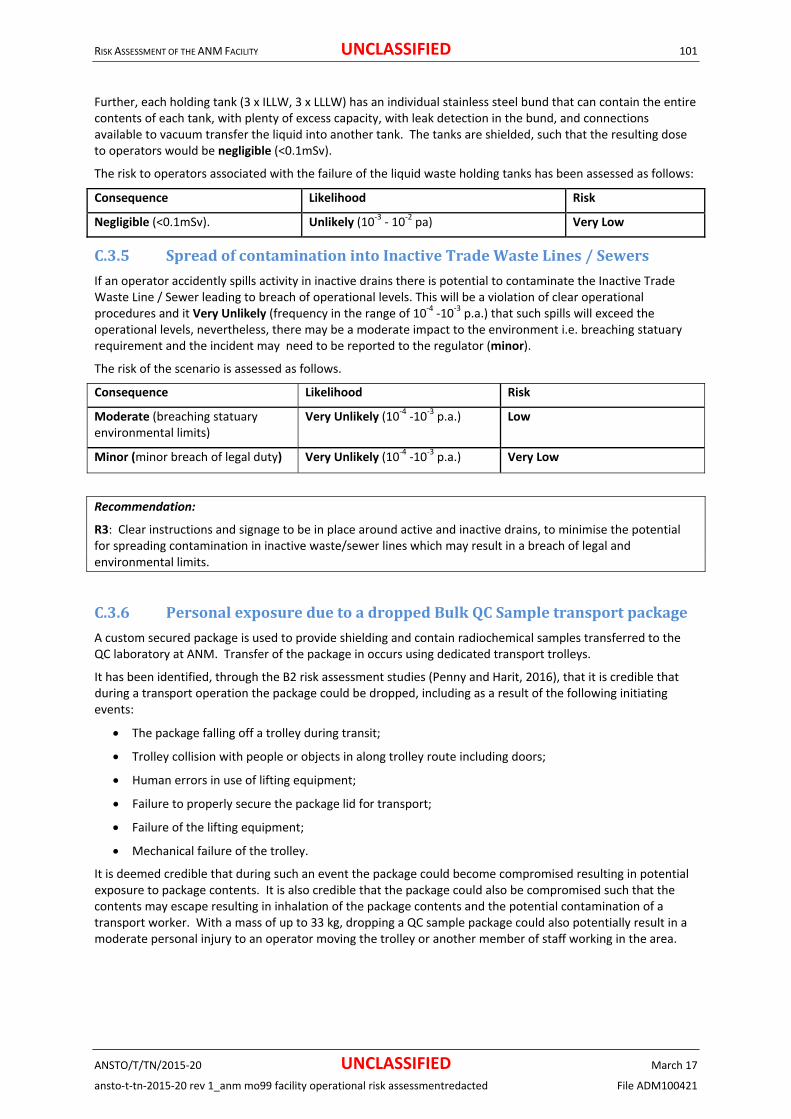
RISK ASSESSMENT OF THE ANM FACILITY UNCLASSIFIED 101
ANSTO/T/TN/2015‐20 UNCLASSIFIED March 17
ansto‐t‐tn‐2015‐20 rev 1_anm mo99 facility operational risk assessmentredacted File ADM100421
Further, each holding tank (3 x ILLW, 3 x LLLW) has an individual stainless steel bund that can contain the entire contents of each tank, with plenty of excess capacity, with leak detection in the bund, and connections available to vacuum transfer the liquid into another tank. The tanks are shielded, such that the resulting dose to operators would be negligible (<0.1mSv).
The risk to operators associated with the failure of the liquid waste holding tanks has been assessed as follows:
Consequence Likelihood Risk
Negligible (<0.1mSv). Unlikely (10‐3 ‐ 10‐2 pa) Very Low
C.3.5 SpreadofcontaminationintoInactiveTradeWasteLines/Sewers
If an operator accidently spills activity in inactive drains there is potential to contaminate the Inactive Trade Waste Line / Sewer leading to breach of operational levels. This will be a violation of clear operational procedures and it Very Unlikely (frequency in the range of 10‐4 ‐10‐3 p.a.) that such spills will exceed the operational levels, nevertheless, there may be a moderate impact to the environment i.e. breaching statuary requirement and the incident may need to be reported to the regulator (minor).
The risk of the scenario is assessed as follows.
Consequence Likelihood Risk
Moderate (breaching statuary environmental limits)
Very Unlikely (10‐4 ‐10‐3 p.a.) Low
Minor (minor breach of legal duty) Very Unlikely (10‐4 ‐10‐3 p.a.) Very Low
Recommendation:
R3: Clear instructions and signage to be in place around active and inactive drains, to minimise the potential for spreading contamination in inactive waste/sewer lines which may result in a breach of legal and environmental limits.
C.3.6 PersonalexposureduetoadroppedBulkQCSampletransportpackage
A custom secured package is used to provide shielding and contain radiochemical samples transferred to the QC laboratory at ANM. Transfer of the package in occurs using dedicated transport trolleys.
It has been identified, through the B2 risk assessment studies (Penny and Harit, 2016), that it is credible that during a transport operation the package could be dropped, including as a result of the following initiating events:
The package falling off a trolley during transit;
Trolley collision with people or objects in along trolley route including doors;
Human errors in use of lifting equipment;
Failure to properly secure the package lid for transport;
Failure of the lifting equipment;
Mechanical failure of the trolley.
It is deemed credible that during such an event the package could become compromised resulting in potential exposure to package contents. It is also credible that the package could also be compromised such that the contents may escape resulting in inhalation of the package contents and the potential contamination of a transport worker. With a mass of up to 33 kg, dropping a QC sample package could also potentially result in a moderate personal injury to an operator moving the trolley or another member of staff working in the area.

RISK ASSESSMENT OF THE ANM FACILITY UNCLASSIFIED 102
ANSTO/T/TN/2015‐20 UNCLASSIFIED March 17
ansto‐t‐tn‐2015‐20 rev 1_anm mo99 facility operational risk assessmentredacted File ADM100421
Figure 19‐ QC Sample Package
The QC sample package is a sturdy design based upon the design of the B(U) packages normally used for transport of bulk Mo‐99. The QC package lid is secured for transport using a bolt down system as shown above. While not tested and qualified, due to the robust nature of the transport package’s construction it is assumed for this assessment that it is equivalent to a Type A package. Therefore it is assumed that maximum release of activity from such an event is limited to 1/1000 of the package contents with maximum intake adsorbed by a transport worker limited to 1/1000 of the release activity.
Staff are trained in pot transfer techniques, and trolleys are provided where required.
The drop of a package is assumed to be a revealed event and immediately identified, with personnel evacuating the area within 30 seconds. Any personal contamination resulting is assumed to be identified and removed within 5 minutes of such an event. Personnel are not expected to return until they, the area, and all equipment involved have been surveyed by Health Physics, and cleared for ongoing operations.
The maximum potential exposure dose, inhalation dose, and Whole Body Dose from a dropped transported ANM Mo99 QC is estimated to be 1.16 μSv, 3.33 µSv, and 4.49 µSv (Penny and Jani, 2016), hence a relatively negligible (<0.1mSv) consequence. However, the maximum contamination dose for this event is assumed to be 477 mSv (i.e. moderate (40‐500mSv skin extremity dose) , based on an exposure time of 5 minutes, and extremity dose (using the syringe model) due to a worker as 62.6 mSv (moderate (40‐500mSv skin extremity dose)) based on the a 10 seconds exposure. (Penny and Jani, 2016). These calculations are based on an assumed bulk QC sample of 21.0Sv.
The calculations have been based upon a transported solution of approximately 2.7 GBq at calibration in 0.6 mL of solution. The draft instruction provided (ANM Operational Readiness Group, 2016) however does not currently indicate how this sample is prepared and some sections of the instruction are contradictory with this assumption. Therefore the operating instructions should be revised to ensure that they reflect this planned model of operations. If the final operating instructions reflect a different operating model than assumed by this assessment, this assessment may need to be revised. Therefore on release of the operating instruction for the QC process this assessment should be reviewed.
Recommendation:
R14: Ensure all ANM Mo99 operating instructions for the dispensing of the QC sample for transport reflect the planned operating conditions set out with in the ANM Mo99 Facility Risk Assessment (TN 148023) and the B2 QC Laboratory Risk Assessment (TN 148388).
The table below calculates the likelihood of the radiological consequences identified for the event. Table 6 – Likelihood of identified consequences associated with drop of ANM QC Bulk Sample

RISK ASSESSMENT OF THE ANM FACILITY UNCLASSIFIED 103
ANSTO/T/TN/2015‐20 UNCLASSIFIED March 17
ansto‐t‐tn‐2015‐20 rev 1_anm mo99 facility operational risk assessmentredacted File ADM100421
ID Item Value References/ Assumptions
A ANM QC sample transfers per year 450 Section Error! Reference
source not found.
B Probability of a drop per transfer 0.003 Human Error (Swain &
Guttman, 1983)
C Adjustment for Low Speed 0.01 Assumed adjustment for
controlled conditions
D Probability package fails 0.01 Type A Package (USNRC,
2003)
E Probability contents escape 0.39 Type A Package (USNRC,
2003)
F Probability of a contamination of operator given contents escape
0.1 Assumed
G Probability of contact with vial during recovery given contents escape
0.01 Assumed
H Likelihood of exposure to QC sample 1.35×10‐4 pa A.B.C.D
I Likelihood of airborne release 5.3×10‐5 pa H.E
J Likelihood of contamination on person 5.3×10‐6 pa I.F
K Likelihood of contact with vial during recovery
5.3×10‐7 pa I.G
Based on the number of ANM QC samples to be transferred per year, and a probability that a dropped load due to human error will result in the Type A package failing to contain its contents and the Probability. The likelihood of operator contact with vial during recovery given the contents is escaped which may result in an skin extremity
dose is assessed to be 5.3×10‐7 pa (i.e. Incredible <10‐6 p.a.). Therefore the risk of receiving an extremity dose is not assessed further.
The risk associated with the scenario described above has been assessed as follows:
Consequence Likelihood Risk
Moderate (1‐20mSv) Very Unlikely (10‐4 ‐ 10‐3 p.a.) Low
Negligible (<0.1mSv)
Whole Body Dose
Very Unlikely (1.35×10‐4 pa) Very Low
Negligible (<0.1mSv)
Whole Body Dose (including inhalation)
Highly Unlikely (5.3×10‐5 pa) Very Low
Moderate (40‐500mSv skin extremity dose)
Extremely Unlikely (5.3×10‐6 pa) Very Low
Recommendation:
R4: As well as ensuring that all appropriate PPE is worn. Procedures within Laboratories should include that routine checks for contamination are undertaken after each activity to minimise the spread of contamination and identify the source of contamination.
C.4 LossofContainment
C.4.1 Leaksofradioactivegasesintothehotcellcontainment
Leaks of radioactive gases into the hotcell environment could occur due to seal leaks in the process containment vessels during the dissolution process under abnormal conditions such as hydrogen converter or

RISK ASSESSMENT OF THE ANM FACILITY UNCLASSIFIED 104
ANSTO/T/TN/2015‐20 UNCLASSIFIED March 17
ansto‐t‐tn‐2015‐20 rev 1_anm mo99 facility operational risk assessmentredacted File ADM100421
condenser failure. Such event involves a process accident with several layers of protection e.g. control interlocks, batch sheets etc. Normally the Process Containment is below atmospheric pressure and results in entry of air into process rather than release of gas into hotcell containment. Therefore, leak of radioactive gases into hotcell containment is considered unlikely (10‐3 ‐ 10‐2 p.a.).
Such leaks are released into the hotcell containment and will be discharged by the Red primary exhaust of Active Ventilation System via the carbon columns and stack filtration. Thus there will be no radiological consequence affecting operating personnel.
Off‐site radiological consequence from this scenario is considered to be lower than for the release of a fresh (undecayed) gas tank previously analysed for the safety assessment of the AVS (Section C.5.3). Previous calculations made for B54 gas tanks (using 8 target plates per run) estimated the maximum off‐site dose as 14µSv (Penny, 2009). With 12 target plates used in the ANM facility the maximum off site public dose is estimated to be 50% higher, 21µSv i.e. minor (20‐300µSv dose off site).
The release could be above normal radioactivity releases to the environment and may also result in a regulatory compliance notice (minor).
The risk of this scenario is assessed as follows.
Consequence Likelihood Risk
Minor (20‐300 µSv dose off site) Unlikely (10‐3 ‐ 10‐2 p.a.) Low
Minor (Regulatory compliance notice)
Unlikely (10‐3 ‐ 10‐2 p.a.) Low.
C.4.2 Overpressurisationofdissolverleadingtoruptureorsignificantleaksfromseals
Over‐pressurisation of the dissolver above the maximum design pressure could potentially be initiated due to the following events.
The pneumatic valve on the inlet of the hydrogen converter spuriously closes during dissolution due to a control fault;
Total power failure for the control of the inlet valve of the hydrogen converter resulting in the valve being closed
The pneumatic valves on the selected gas tank spuriously closes during dissolution.
The pressure is monitored by the control system which would automatically cause the dissolution reaction to be cooled down. This would slow down the reaction and allow operators to take suitable remedial action. In the case of the inlet valve to the hydrogen converter closing spuriously it would be possible for the operators to manually open the valve and prevent build‐up of pressure.
In the case of the pneumatic valve of the selected gas tank spuriously closing, the control system would detect over pressure and automatically connect the second evacuated gas tank.
If the above stated control measures fail, the overpressure generated would be relieved by the rupture of the bursting disc. The piping downstream of the bursting disc is directly connected to the dedicated gas tank with no other valves in the piping.
The radiological consequence, assuming failure of all the identified controls, is release of radioactive material into the hotcell containment which would then be exhausted by the Red Primary Exhaust of the AVS to the stack discharge system. The hotcell containment would minimise air borne contamination in the front of cell area.
The off‐site radiological consequence of the reference accident for the siting licence of the ANM Mo99 facility has been previously estimated as 0.28mSv and the on‐site radiological consequence has been estimated as 1.82mSv, based on night time exposure (Barton, 2014). The reference accident considered a radioactivity inventory of two dissolver runs. Therefore, radiological consequence in this scenario is assessed to be at least 50% lower i.e. minor (off‐site dose 20‐300 µSv off site dose and (0.1‐1mSv) dose to personnel on site).
Appendix B section B.2.1 analyses the likelihood of this scenario. The likelihood of this scenario is estimated as 5.90 x10‐6 p.a. i.e. Extremely Unlikely.

RISK ASSESSMENT OF THE ANM FACILITY UNCLASSIFIED 105
ANSTO/T/TN/2015‐20 UNCLASSIFIED March 17
ansto‐t‐tn‐2015‐20 rev 1_anm mo99 facility operational risk assessmentredacted File ADM100421
The risk of this scenario is assessed as follows.
Consequence Likelihood Risk
Minor (20‐300µSv dose off site; dose to operators 0.1‐1 mSv)
Extremely Unlikely (10‐6 ‐ 10‐5
p.a.) Very Low
Moderate (Regulatory Compliance ) Extremely Unlikely (10‐6 ‐ 10‐5
p.a.) Very Low
C.4.3 ImpactordamagetohotcellPenetrationSealing
Failure of any hotcell penetration sealing could compromise the integrity of the hotcell containment boundary. The four main mechanisms by which this could occur are mechanical impact, wear and tear (manipulator booting), corrosion, or seismic event.
Significant mechanical impacts could be caused by errors during crane movements. The crane design features, administrative controls, and operator training should ensure that such an event does not occur. This has previously been assessed for fault associated with the rear of cell crane in Section C.2.3, which concluded that over‐travel of the crane, resulting in a flask damaging other equipment within the facility was Very Unlikely (10‐4 ‐ 10‐3 p.a.). Similar features are identified for other cranes within the facility in [Ali, 2015].
Such an impact is considered to damage the master‐slave manipulators or any other penetration impacted, in such a way as to compromise the integrity of the hotcell containment boundary. However, it would not cause a coincident loss of ventilation. As such, the radiological consequences of this event are considered to be negligible (<0.1 mSv). The likelihood of an independent failure of the ventilation system at the same time as this event is considered not credible.
The manipulator booting can be damaged in the normal course of operations through wear and tear. Detection of such damage is either visual (observing the deflation of the booting) or by hotcell differential pressure. Such failures should not result in a total loss of cell negative pressure, as the ventilation system will compensate.
All piping penetrations have been made from 316L Stainless Steel, suitable for both alkaline and acidic materials used in the hotcells. Power and control penetrations are also made from stainless steel. The manipulator booting is made from plastic, and is therefore not subject to corrosion.
Other failure modes, such as seal wear‐out or human error during maintenance, have also been identified. The magnitude of the hotcell penetration failure would be much smaller in these cases, compared with the failure modes previously discussed. As with the manipulator booting, the cell differential pressure provides indication, and the ventilation system will ensure that cell negative pressure is maintained.
The risk associated with the scenario described above has been assessed as follows:
Consequence Likelihood Risk
Negligible (<0.1mSv). Very Unlikely (10‐4 ‐ 10‐3 pa) Very Low
C.4.4 Excessnegativepressureresultinginimplosiondamage
Spurious opening of the modulating valves of the AVS outlet piping of hotcells coincident with spurious closing of the inlet valves could cause excess negative pressure resulting in possible implosion damage.
The inlet valve in the production hotcells is a motorised valve which modulates flow into the hotcell using a flow rate measurement, and is designed fail‐last on loss of power. The modulating valves on cell outlets as well as RP3, RP4 branch headers are also designed to fail last (Perera, 2015c).
Risks of implosion damage in the DCELL:
With the provision of diverse and redundant vacuum break devices the likelihood of excess negative pressure in the DCELL resulting in implosion is considered incredible (< 10‐6 p.a.) as estimated in hotcell Containment Risk Assessment.
Risks of Implosion damage in the other hotcells (other than DCELL).
For all other cells a single vacuum break device is used on the outlet pipe or on the outlet header pipe. There are two modulating valves on the AVS exhaust, one on the cell outlet and another on the header of RP2, RP3 or

RISK ASSESSMENT OF THE ANM FACILITY UNCLASSIFIED 106
ANSTO/T/TN/2015‐20 UNCLASSIFIED March 17
ansto‐t‐tn‐2015‐20 rev 1_anm mo99 facility operational risk assessmentredacted File ADM100421
RP4. Thus there is redundancy in the provisions for adjusting of negative pressure. The likelihood of excessive negative pressure resulting in implosion damage is estimated as < 10‐6 p.a. (incredible).
Because the accidents above are considered incredible, the events are not considered any further.
C.4.5 ExcesspositivepressureinDCELLorHCELLresultingindamagetocontainment
Excess positive pressure could result in the DCELL or the HCELL if the inlet and outlet valves both close spuriously and hence causing heating up of the contained volume of air in these cells due to heart sources present. Both inlet an outlet modulating valves of the DCELL and HCELL are designed fail‐last on loss of power. Therefore loss of power would not initiate such event. It would require the extremely unlikely spurious closure of two separate valves as well as the failure of the pressure relief device.
The likelihood of excess positive pressure in DCELL is estimated as 3.3x10‐7 p.a. The likelihood of excess negative pressure in the HCELL is estimated as 3.7x10‐7 p.a. Thus the likelihood of excess positive pressure resulting in hotcell containment in any of hotcells is estimated as 7 x 10‐7 p.a. (incredible). (Perera, 2015c).
Because the accidents above are considered incredible, the event is not considered any further.
C.4.6 OvertemperatureinDCELLorHCELLcausingdamagetocontainment
Loss of AVS exhaust in DCELL or HCELL could cause cell ambient temperature to rise and cause damage to hotcell containment e.g. manipulator boots. Such failure could occur due to total power failure (both duty and standby) to the AVS fans or the AVS extraction failure.
In addition, to the standby generator power supply available in the ANM facility building provision is made available to connect a portable standby generator to the AVS fans power supply circuit to maintain operation of fans in an emergency if ever the need arises.
The hotcell containment assessment (Perera, 2015c) estimates the likelihood of this scenario as 3.2x10‐2 p.a. (likely). The direct radiological consequence of this event is negligible as the airborne radioactive materials would still be contained within the process containment system. However there could be indirect radiological consequence during planned recovery operations. Such radiological consequence is expected to be limited to minor (0.1‐1mSv dose).
The risk associated with the scenario described above has been assessed as follows:
Consequence Likelihood Risk
Minor (0.1‐1mSv). Likely (10‐2 ‐ 10‐1 pa) Very Low
C.4.7 Lossofhotcellcontainmentduetospuriousoperationofvacuumbreakdevices
Spurious operation of vacuum break devices would affect the AVS extract from hotcells and may cause negative pressures in hotcell containment to be reduced or lost. AVS alarms would detect this condition. On the detection of Level 2 alarms operators will leave the hotcell area after ensuring process safety.
The radiological consequence of loss of Red primary exhaust under normal operations has been assessed in the Section C.5.2, as negligible (<0.1mSv dose).
The vacuum break devices are simple and passive devices and will be inspected and checked regularly to ensure reliability. The vacuum break settings are to be verified and tested during commissioning.
The risk associated with the scenario described above has been assessed as follows:
Consequence Likelihood Risk
Negligible (<0.1mSv). Likely (10‐2 ‐ 10‐1 pa) Low
Recommendation:
R5: maintenance procedures should have clear instruction for vacuum break devices to be inspected and checked regularly to maintain their reliability

RISK ASSESSMENT OF THE ANM FACILITY UNCLASSIFIED 107
ANSTO/T/TN/2015‐20 UNCLASSIFIED March 17
ansto‐t‐tn‐2015‐20 rev 1_anm mo99 facility operational risk assessmentredacted File ADM100421
C.4.8 OverpressureofLiquidWasteDecayTanks
The liquid waste decay tanks are normally connected to the active ventilation system. If this connection was isolated in error, there is a possibility of over‐pressurising the tank.
The only credible source of pressure in this vessel is the PULSAIR nitrogen stirring. This system introduces a fixed volume of nitrogen to ensure the tank contents are well mixed prior to sampling or transport.
The nitrogen pulse system is interlocked against the tank pressure, preventing pulsing if the tank is not connected to the ventilation system. The source tank used to provide nitrogen is designed so it is not possible to be connected to both the nitrogen supply and the PULSAIR system simultaneously. The source tank is also pressure‐regulated to ensure that it cannot contain a volume of nitrogen that, if the full contents were released into an isolated decay tank, would result in the decay tank being over‐pressurised.
The tanks have a second independent skin, and are located inside a concrete bunker. Therefore even if such an overpressure event were to occur, it is Extremely Unlikely (frequency in the range of 10‐5 ‐ 10‐6 pa) that anyone would be exposed to the waste during an overpressure event (i.e. negligible, <0.1mSv). The main consequence therefore is the damage to plant leading to loss of production (Moderate, loss of production <1 month / report to regulator). The availability of additional storage capacity should allow production to continue without the need for an extended outage.
The risk to operators associated with the overpressure of the liquid waste decay tanks has been assessed as follows:
Consequence Likelihood Risk
Negligible (<0.1mSv) Extremely Unlikely (10‐6 ‐ 10‐5 pa) Very Low
The risk of plant damage associated with the overpressure of a intermediate level liquid waste decay tank has been assessed as follows:
Consequence Likelihood Risk
Moderate (loss of production <1 month / report to regulator).
Extremely Unlikely (10‐6 ‐ 10‐5 pa) Very Low
C.4.9 Lossofcontainmentinthegastransferlines
Failure of a gas transfer line such as a leak resulting in loss of containment would not normally cause a release of radioactive gases and would instead draw in air from the ambient atmosphere into to gas tanks. However, if such leak or rupture is coincident with pressurisation, there could be a release of airborne radioactive material in the basement area, which is unmanned. Thus there will be no significant radiation intake by operations personnel due to such event. Any release of radioactivity to the environment will be via the secondary exhaust system and its filtration. The off‐site radiological consequence affecting members of the public is assessed Negligible (<20µSv dose to members of the public and <0.1mSv dose to staff).
Loss of containment would require an abnormal process event to occur resulting in pressurisation and subsequent failure of a pipe or seal in a flange, which are designed to pressure of 1200kPa and pressure tested to 1918kPa. Any leaks in the transfer lines would be detected during the vacuum tests being carried out prior to a production run. Therefore, the likelihood is conservatively assumed as Unlikely (frequency in the range of 10‐3 ‐ 10‐2 p.a.).
The risk associated with such scenario is assessed as follows:
Consequence Likelihood Risk
Negligible (<20µSv dose to members of the public)
Unlikely (10‐3 ‐ 10‐2 p.a.) Very Low
Negligible (dose to personnel on‐site < 0.1mSv)
Unlikely (10‐3 ‐ 10‐2 p.a.) Very Low

RISK ASSESSMENT OF THE ANM FACILITY UNCLASSIFIED 108
ANSTO/T/TN/2015‐20 UNCLASSIFIED March 17
ansto‐t‐tn‐2015‐20 rev 1_anm mo99 facility operational risk assessmentredacted File ADM100421
C.4.10 ImpactordamagetoAirlockleadingtolossofcontainment
Failure of any Airlock could compromise the integrity of various areas within the ANM facility containment boundary. However, it is considered that the ventilation system will ensure that negative pressure is maintained, and the radiological impact is negligible (0‐0.1mSv).
The four main mechanisms although considered Unlikely (10‐3 ‐ 10‐2 p.a.), by which this fault could occur are mechanical impact, wear and tear, corrosion, or seismic event.
Mechanical impacts could be caused by errors during personnel/equipment movements. Administrative controls, provide clear unobstructed routes, and operator training should ensure that such an event does not occur.
Other failure modes, such as seal wear‐out or human error leaving the airlock door open are a possibility however, periodic visual inspection of seals and visual light alarm are there to minimise the potential likelihood and impact of the fault.
The risk associated with the scenario described above has been assessed as follows:
Consequence Likelihood Risk
Negligible (<0.1mSv) Unlikely (10‐3 ‐ 10‐2 pa) Very Low
Recommendation:
R6: To avoid potential breach of containment and damage to safety systems. Administrative controls (i.e. operator training, clear unobstructed routes, periodic visual inspection, etc.), and physical impact protection (cabinets, bollards, conduits, etc.) should be provided around safety systems and containment barriers.
C.5 FailureoftheAVSSystem
C.5.1 RedprimaryexhaustventilationfailurepriortoaMo‐99productionrun
Failure of the Red primary exhaust prior to a Mo‐99 production run could cause airborne contamination inside the hotcells to diffuse out slowly. Red primary exhaust applies to each of the production and service hotcells. Although, each hotcell has a significant quantity of radioactivity, such activity is considerably less than what would be inside the dissolution cell (DCELL) during a production run.
The radiological consequence of the loss of red primary exhaust ventilation is assessed to be negligible (< 0.1mSv) taking into account the following factors.
There will be no liquid radioactive material inside any of the production cells prior to a production run as these will have been be transferred out of the cells either as product in BU containers or as liquid waste to liquid waste tanks during the previous production run.
The largest accumulated radioactive inventory in the hotcells is from the spent uranium filter (SUF) cups and in the resins in the purification columns. Such activity is mostly in solid form and only a small fraction of these contribute to airborne contamination inside the cells.
The filtration columns are capped and sealed after use and therefore minimises the amount of leak of volatile waste products. e.g. Iodine.
The cells are well sealed.
Loss of Red primary exhaust will provide an audible and visual alarm which is also relayed to the Emergency Response Team (ERT). Operating personnel are expected to evacuate the area within a relatively short period of about 1‐5 minutes (after ensuring that process is safe).
The FTA results within the Safety and Reliability Review of the ANM Mo99 Active Ventilation System (Perera, 2015) show that the accident frequency of total failure of Red primary exhaust is 4.40x10‐2 p.a.(Likely) (i.e. approximately once per 23 years). Such failure could occur sometimes over the life of the facility. The dominant cause of the system failure is the mains power failure followed by standby power failure. The risk associated with the scenario described above has been assessed as follows:
Consequence Likelihood Risk

RISK ASSESSMENT OF THE ANM FACILITY UNCLASSIFIED 109
ANSTO/T/TN/2015‐20 UNCLASSIFIED March 17
ansto‐t‐tn‐2015‐20 rev 1_anm mo99 facility operational risk assessmentredacted File ADM100421
Negligible (<0.1mSv dose) Likely (10‐2 ‐ 10‐1 p.a.) Very Low
Even if the operators fail to evacuate the area within 5 minutes, and delay leaving the area by a much longer period of about 1 hour, the estimated radiological consequence would still be below 0.1mSv. The likelihood of such scenarios is estimated as 4.4x10‐4 p.a. (Very Unlikely).
The risk associated with such scenario is assessed as follows:
Consequence Likelihood Risk
Negligible (<0.1mSv dose) Very Unlikely (10‐4 ‐ 10‐3 p.a.) Very Low
C.5.2 RedprimaryexhaustventilationfailureduringanormalMo‐99productionrun
Failure of the Red primary exhaust during a normal Mo‐99 production run could cause airborne contamination inside the hotcells to diffuse out slowly. Although there will be a significantly larger quantity of radioactive materials in the production hotcells i.e. DCELL1, HCELL1, PCELL1, ECEL1, and PKGC1, such activity is mostly contained within the production system of tanks and piping. However there could be some anticipated minor liquid leaks etc. which could increase the airborne contamination level Negligible (<0.1mSv dose) in the production hotcells.
The FTA results within the Safety and Reliability Review of the ANM Mo99 Active Ventilation System (Perera, 2015) show that the accident frequency of total failure of Red primary exhaust is 4.40x10‐2 p.a.(Likely) (i.e. approximately once per 23 years). Such failure could occur sometimes over the life of the facility. The dominant cause of the system failure is the mains power failure followed by standby power failure. The risk associated with the scenario described above has been assessed as follows:
Consequence Likelihood Risk
Negligible (<0.1mSv dose) Likely (10‐2 ‐ 10‐1 p.a.) Very Low
Even if the operators fail to evacuate the area within a reasonable period, but delay leaving the area for a much longer period about 1 hour, the radiological consequence would still remain Negligible (<0.1mSv dose). The likelihood of such a scenario is estimated as 4.4x10‐4 p.a. (Very Unlikely).
The risk associated with such a scenario is assessed as follows:
Consequence Likelihood Risk
Negligible (<0.1mSv dose) Very Unlikely (10‐4 ‐ 10‐3 p.a.) Very Low
C.5.3 Redprimaryexhaustventilationfailureduringanaccidentalreleaseofradioactivityintoanyoftheproductionhotcells
Failure of the Red primary exhaust during an accidental release of radioactivity could cause a much higher level of airborne contamination inside the hotcells, than during a normal production run. The radiological consequence of the loss of red primary exhaust ventilation coincident with the accidental release of radioactivity inside the hotcells is assessed to be Moderate (1‐20mSv) as per the consequence assessment (Penny, 2014). This based on operators response and evacuation within 5 minutes to an audible and visual alarm. This alarm would also be relayed to the Emergency Response Team (ERT).
The loss of Red primary exhaust coincident with a major accident inside the hotcells with release of radioactivity into the hotcell containment is estimated as 4.4x10‐5 p.a. (Highly Unlikely).
This estimate is still considered conservative due to multiple controls which exists to ensure that there are no leaks in the process system prior to a production run, and to ensure that there is no pressurisation. If a major leak occurs, the radioactive materials will be present in the cell only for a short period under normal extract ventilation conditions of 5 air changes per hour (Perera, 2015).
The results of the Fault Tree Analysis is included in the Safety and Reliability Review of the ANM Mo99 Active Ventilation System (Perera, 2015).
The risk associated with the scenario described above has been assessed as follows:

RISK ASSESSMENT OF THE ANM FACILITY UNCLASSIFIED 110
ANSTO/T/TN/2015‐20 UNCLASSIFIED March 17
ansto‐t‐tn‐2015‐20 rev 1_anm mo99 facility operational risk assessmentredacted File ADM100421
Consequence Likelihood Risk
Moderate (1‐20mSv dose) Highly Unlikely(10‐5 ‐ 10‐4 p.a.)
Very Low
If the operators fail to evacuate the area within 5 minutes, the radiological consequence could increase to major (20‐100mSv). The likelihood of such scenario is estimated to be <10‐6 p.a. (incredible).
The risk associated with such a scenario is assessed as follows:
Consequence Likelihood Risk
Major (20‐100mSv dose) Incredible (< 10‐6 p.a.)
Not Assessed
Recommendation:
R7: In the event of red primary exhaust ventilation, failure operators must immediately evacuate the area to minimise dose uptake.
C.5.4 Redprimaryexhaustventilationfailureduringperiodsofmaintenanceaccesstohotcells
Maintenance access to a hotcell is required on average around once per year for each hotcell. With 12 hotcells connected to the Red primary exhaust the frequency of maintenance access is estimated as 1/12 = 8.33 per year. Allowing for 24 hours for such maintenance activity, the probability that a hotcell is under maintenance is estimated as 8.33 x 24/8760 = 0.023.
The frequency of Red primary exhaust failure was estimated by the FTA results within the Safety and Reliability Review of the ANM Mo99 Active Ventilation System (Perera, 2015) show that the accident frequency of total failure of Red primary exhaust is 4.40x10‐2 p.a. (i.e. approximately once per 23 years). Such failure could occur sometimes over the life of the facility. The dominant cause of the system failure is the mains power failure followed by standby power failure.
Thus the frequency of Red primary exhaust failure during periods of maintenance access to a hotcell is estimated as 4.4x10‐2 x 0.023 = 1.01x10‐3 p.a. i.e. Unlikely.
Total failure of Red primary exhaust will generate a level 2 alarm requiring evacuation. Also prior to maintenance access being granted to a hotcell, it is cleared of any significant radioactive items. Access can be gained only to the space between hotcell shielding and containment box. The first step in the work inside the hotcell would be to where necessary adequately decontaminate the hotcell of any loose surface contamination. Maintenance personnel would wear appropriate PPE such as lab coats, masks and gloves. Health Physics will confirm level of contamination prior to entry to ensure dose are as expected Thus the radiological consequence of this scenario is assessed as minor (0.1‐1mSv).
The risk associated with the scenario described above has been assessed as follows:
Consequence Likelihood Risk
Minor (0.1‐1mSV dose) Unlikely (10‐3 ‐ 10‐2p.a.) Very Low
C.5.5 Accidentalreleaseofabove‐normalradioactivitybyselectingthewronggastankforrelease
Accidental release of above normal radioactivity to the environment via the stacks could occur if the wrong tank is selected for release due to human error. Multiple radiation detectors in the exhaust ducts and gas transfer lines detect such above normal releases so that appropriate response could be made. It is possible to stop the release and then check and select the correct tank for release.
The HEPA and carbon–iodine filters as well as the carbon columns filter a significant proportion of the radioactive materials released to the environment via the stack discharge system. Any such release will be immediately detected via the on‐line monitoring of stack discharges.

RISK ASSESSMENT OF THE ANM FACILITY UNCLASSIFIED 111
ANSTO/T/TN/2015‐20 UNCLASSIFIED March 17
ansto‐t‐tn‐2015‐20 rev 1_anm mo99 facility operational risk assessmentredacted File ADM100421
Previous calculations made for the existing B54 gas tanks (using 8 target plates per run) estimated the maximum off‐site dose as 14µSv (Penny, 2009). With 12 target plates used in the ANM facility the maximum off site public dose is estimated as 50% higher, 21µSv i.e. Minor (dose to members of the public in the range 20‐300 µSv) (Penny, 2006). The maximum on‐site dose to personnel in B54 facility was estimated as 59 µSv. The corresponding on‐site dose to personnel in the ANM facility is estimated as 59µSv x 1.5 = 88.5µSv i.e. Negligible (dose to personnel on‐site < 0.1mSv).
The risks associated with such scenario for members of the public and for on‐site personnel are assessed as follows:
Consequence Likelihood Risk
Minor (dose to members of the public in the range 20‐300 µSv).
Likely (10‐2 ‐ 10‐1 p.a.) Low
Negligible (dose to personnel on‐site < 0.1mSv)
Likely (10‐2 ‐ 10‐1 p.a.) Very Low
C.5.6 Airbornecontaminationinthebuildingresultingfrombackflowsfromthestack
The possibility of airborne contamination in the Blue and White areas of the ANM building due to back flow from the stack was identified in the system level FMEA.
Such event could possibly occur with complete failure of both primary and secondary exhaust ventilation systems and if the outlet dampers of the secondary exhaust remain open. It is however a Very Unlikely (frequency in the range of 10‐4 ‐ 10‐3 p.a.) event as the outlet dampers of secondary exhaust systems is designed to be fail‐closed. Significant blockage of the stack causing a back pressure resulting in back flows from the primary exhaust system to the secondary exhaust system is considered not credible.
Any backflows via diffusion will have to pass‐through the HEPA filters in the secondary exhaust. If the red primary exhaust system remains in operation with the secondary exhaust system failed, then the stack discharges would take the path of least resistance and thus even if the outlet dampers of the secondary exhaust remain open there will be no significant back flows to the building via the secondary ducts and HEPA filters.
The building will be evacuated in the event of complete failure of the primary and secondary exhaust. Thus any potential airborne contamination in the Blue and White areas will not be significant i.e. Negligible (<0.1mSv dose to personnel).
The risk associated with such scenario is assessed as follows:
Consequence Likelihood Risk
Negligible (<0.1mSv dose to personnel).
Very Unlikely (10‐4 ‐ 10‐3 p.a.) Very Low
C.5.7 Airbornecontaminationmonitoringinthefrontofcellareafollowingaprocessaccident
If a process accident occurs in the hotcells, the Red primary exhaust of the AVS would limit the airborne contamination outside the hotcell containment.
The AVS availability for Red primary exhaust is rated as 99.99%. There are multiple air samplers located in the front of cells and rear of cells area which should detect above normal airborne contamination.
Thus the coincident failure of AVS, AVS alarms, and the air sampler radiation monitor alarms following a process accident is considered incredible (< 10‐6 p.a.). (Perera, 2015)
Because the accidents above are considered incredible, the event is not considered any further.

RISK ASSESSMENT OF THE ANM FACILITY UNCLASSIFIED 112
ANSTO/T/TN/2015‐20 UNCLASSIFIED March 17
ansto‐t‐tn‐2015‐20 rev 1_anm mo99 facility operational risk assessmentredacted File ADM100421
C.5.8 AirbornecontaminationmonitoringinthebasementareafollowingaleakofgastanksorAVSducts
The basement area is a prohibited area. Access is allowed only after a 3 day delay following a process shutdown and after careful preparations, including radiation and airborne contamination checks.
The basement area has air samplers in various locations including those within shielded areas not normally accessible. Any release of airborne activity due to leaks in the gas tanks or AVS ducts will be detected by the air samplers and associated alarms. There are multiple air samplers (9 Nos) in the basement area which would detect such leaks reliably.
The gas transfer pipes, gas tanks and AVS ducts are of high integrity and the occurrence of significant leaks is considered unlikely (frequency in the region of 10‐3 – 10‐2 p.a.) during normal operational service life. Any abnormal release of activity in the basement will also be detected by the online stack discharge monitoring system. Thus the occurrence of a radioactive gas leak being undetected by the air samplers or stack discharge monitoring is assessed to be Highly Unlikely (frequency in the region of 10‐5 – 10‐4 p.a.).
There will be controlled access procedures to the basement and instructions to clearly state the pre‐requisites to enter the basement Health Physics support will be sought to advice on the estimated potential dose exposure, in accordance with hazard notice boards and Local rules.
Access to the gas decay tanks requires shielding to be removed and that requires Health Physics support. The duration of access to the basement area is also limited (around 4‐8 hours), therefore, the worst case radiological consequence from inhalation of airborne activity is assessed to be in the range of 1‐20mSv i.e. moderate radiological consequence.
Recommendation:
R8: Controlled access procedures to the basement and instructions to clearly state, the pre‐requisites to enter the basement Health Physics support will be sought to advise on the estimated potential dose exposure. Hazard notice boards and Local rules should be established and displayed
The risk associated with the scenario described above, generally applicable to all areas has been assessed as follows:
Consequence Likelihood Risk
Moderate (1‐20mSv dose) Highly Unlikely (10‐5 ‐ 10‐4 p.a.) Very Low
C.6 OperatorExposedtohighradiationduringhotcellOperations
C.6.1 SpuriousopeningoftopshielddoororgatevalveduetocontrolfailureinDCELLwithoutaflaskinplace
Dose rate calculations have shown that the unshielded dose rates under the shield door from various radioactive sources within the DCELL cell is 12.4Sv/h (Alam, 2015).
The above estimated dose rate is at a location under the shield door are based on direct shine , but takes into account any local shielding at the sources and also where applicable the 9mm thick steel shell of the containment box. An operator standing on top of the hotcell roof for flask loading operations would not be exposed to direct radiation exposure but will be exposed to scattered radiation. There is also an additional 2‐3 meters of distance to an operator than that considered in the dose rate calculation.
Dose rate measurements taken in B54 Mo‐99 production hotcells show that while the direct shine from radiation sources is 3.9Sv/h, the dose at a distance of 0.5m sideways is only 12mSv/h (Alam, 2015). This is a reduction by a factor of 3900/12 = 325. The physical layout and geometry in ANM Mo99 facility is quite different and therefore a much more conservative and rounded off reduction factor of 100 is used to derive a realistic but conservative dose rate for accidental radiation exposure to personnel in the ANM facility for DCELL operations. The dose rate is estimated as 12400/100 = 124mSv/h. Radiation monitors in this area would provide warning and the radiological consequence based on 30 second exposure is assessed as 124/120 = 1.04mSv i.e. Moderate radiological consequence (1‐20mSv).
The likelihood of this event is assessed as follows.
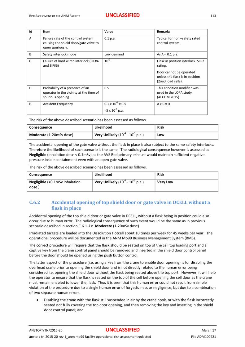
RISK ASSESSMENT OF THE ANM FACILITY UNCLASSIFIED 113
ANSTO/T/TN/2015‐20 UNCLASSIFIED March 17
ansto‐t‐tn‐2015‐20 rev 1_anm mo99 facility operational risk assessmentredacted File ADM100421
Id Item Value Remarks
A Failure rate of the control system causing the shield door/gate valve to open spuriously.
0.1 p.a. Typical for non –safety rated control system.
B Safety interlock mode Low demand As A < 0.1 p.a.
C Failure of hard wired interlock (SIF#4 and SIF#6)
10‐2 Flask in position interlock. SIL‐2 rating.
Door cannot be operated unless the flask is in position (2oo3 load cells).
D Probability of a presence of an operator in the vicinity at the time of spurious opening.
0.5 This condition modifier was used in the LOPA study (AECOM 2015).
E Accident Frequency 0.1 x 10‐2 x 0.5
=5 x 10‐4 p.a.
A x C x D
The risk of the above described scenario has been assessed as follows.
Consequence Likelihood Risk
Moderate (1‐20mSv dose) Very Unlikely (10‐4 ‐ 10‐3 p.a.) Low
The accidental opening of the gate valve without the flask in place is also subject to the same safety interlocks. Therefore the likelihood of such scenario is the same. The radiological consequence however is assessed as Negligible (inhalation dose < 0.1mSv) as the AVS Red primary exhaust would maintain sufficient negative pressure inside containment even with an open gate valve.
The risk of the above described scenario has been assessed as follows.
Consequence Likelihood Risk
Negligible (<0.1mSv inhalation dose )
Very Unlikely (10‐4 ‐ 10‐3 p.a.) Very Low
C.6.2 AccidentalopeningoftopshielddoororgatevalveinDCELLwithoutaflaskinplace
Accidental opening of the top shield door or gate valve in DCELL, without a flask being in position could also occur due to human error. The radiological consequence of such event would be the same as in previous scenario described in section C.6.1. i.e. Moderate (1‐20mSv dose)
Irradiated targets are loaded into the Dissolution Hotcell about 10 times per week for 45 weeks per year. The operational procedure will be documented in the ANM Mo99 Business Management System (BMS).
The correct procedure will require that the flask should be seated on top of the cell top loading port and a captive key from the crane control panel should be removed and inserted in the shield door control panel before the door should be opened using the push button control.
The latter aspect of the procedure (i.e. using a key from the crane to enable door opening) is for disabling the overhead crane prior to opening the shield door and is not directly related to the human error being considered i.e. opening the shield door without the flask being seated above the top port. However, it will help the operator to ensure that the flask is seated on the top of the cell before opening the cell door as the crane must remain enabled to lower the flask. Thus it is seen that this human error could not result from simple violation of the procedure due to a single human error of forgetfulness or negligence, but due to a combination of two separate human errors.
Disabling the crane with the flask still suspended in air by the crane hook, or with the flask incorrectly seated not fully covering the top door opening, and then removing the key and inserting in the shield door control panel; and

RISK ASSESSMENT OF THE ANM FACILITY UNCLASSIFIED 114
ANSTO/T/TN/2015‐20 UNCLASSIFIED March 17
ansto‐t‐tn‐2015‐20 rev 1_anm mo99 facility operational risk assessmentredacted File ADM100421
Operating the door controls to open the door without ensuring that the flask is correctly seated above the top door.
As discussed in (section 4.1 of ADM 100421 ‐ 20 Feb 2015 by Perera, 2015b). The first human error itself is a violation of the correct procedure. A human error probability of 3x10‐3 is assigned which is appropriate for human error associated with a written procedure of short lists (< 10 items) (NUREG/CR 1278, 1983 Table 5‐11).
An order of magnitude higher estimate of 3x10‐2 (than the NUREG data 3x10‐3) is assigned as the conditional probability for the second human error given the occurrence of the first human error.
The overall human error per loading operation is thus estimated as 3x10‐3 x 3x 10‐2= 9x10‐5 .The human error frequency of attempting open shield door thus posing a challenge to safety is estimated as 450 x 9x10‐5 = 4.05 x 10‐2 p.a..
A hard wired SIL 2 (10‐2) interlock system using load cells in 2oo3 configuration detects and confirms the presence and the correct placement of the flask on the top of the cell and prevents opening of the cell door and gate valve if the presence and correct placement is not confirmed.
Thus, the overall likelihood for this event is estimated as 4.05 x 10‐2 p.a. x 10‐2.≈ 4.05 x10‐4 p.a.
Therefore the likelihood of accidental opening the top shield door of the dissolution hotcell without having a flask being seated above the top port is assessed to be Very Unlikely, i.e. in the range 10‐4 ‐ 10‐3 p.a.
The risk of such scenario is assessed as follows.
Consequence Likelihood Risk
Moderate (1‐20mSv dose) Very Unlikely (10‐4 ‐ 10‐3 p.a.) Low
The accidental removal of the flask using the crane without closing the gate valve is also subject to the same safety interlocks as for the shield door. Therefore the likelihood of such scenario is the same. The radiological consequence however is assessed as Negligible (inhalation dose < 0.1mSv) as the AVS Red primary exhaust would maintain sufficient negative pressure inside containment even with an open gate valve.
The risk of the above described scenario has been assessed as follows.
Consequence Likelihood Risk
Negligible (<0.1mSv inhalation dose )
Very Unlikely (10‐4 ‐ 10‐3 p.a.) Very Low
C.6.3 AccidentalremovaloftheflaskfromthetopofDCELLwithoutfirstclosingtheshielddoorandthegatevalve
The accidental removal of the target transfer flask from the top of DCELL without first closing the shied door or the gate valve would have the same radiological consequence as in previous scenario described in section C.6.1.
The likelihood of this event is assessed as follows.
Id Item Value Remarks
A Frequency of flask operations in DCELL
450 p.a. 10 per week for 45 weeks p.a.
B Human error of attempting to remove the flask without closing the shield door
3 x 10‐3 Violation of the procedure
(NUREG/CR 1278, 1983 Table 5‐11).
C Unmitigated initiating event frequency
450x3 x10‐3
=1.35 p.a.
A x B
D Safety interlock mode Continuous As C > 1 p.a.
E Failure of Captive key interlock (SIF#5a)
<1.14x10‐7 per hour
(<1.0x10‐2 p.a.)
A robust electro‐mechanical safety interlocks system. Minimum SIL‐2 rating in continuous mode.

RISK ASSESSMENT OF THE ANM FACILITY UNCLASSIFIED 115
ANSTO/T/TN/2015‐20 UNCLASSIFIED March 17
ansto‐t‐tn‐2015‐20 rev 1_anm mo99 facility operational risk assessmentredacted File ADM100421
F Accident Frequency < 10‐2 p.a. E
With continuous mode accident frequency is the same as failure rate of the safety system when there are no condition modifiers that could reduce accident frequency.
The risk of the above described scenario has been assessed as follows.
Consequence Likelihood Risk
Moderate (1‐20mSv dose) Unlikely (10‐3 ‐ 10‐2 p.a.) Low
The accidental removal of the flask using the crane without closing the gate valve is also subject to the same safety interlocks as for the shield door. Therefore the likelihood of such scenario is the same. The radiological consequence however is assessed as Negligible (inhalation dose < 0.1mSv) as the AVS Red primary exhaust would maintain sufficient negative pressure inside containment even with an open gate valve.
The risk of the above described scenario has been assessed as follows.
Consequence Likelihood Risk
Negligible (<0.1mSv inhalation dose )
Unlikely (10‐3 ‐ 10‐2 p.a.) Very Low
C.6.4 AccidentalopeningoftopshielddoororgatevalveinHCELL
The top shield door and gate valve in the HCELL are opened only for infrequent replacement of the hydrogen converters in HCELL. The radioactive inventory in the HCELL is relatively small compared to other hotcells. The dose rate at the location of the shield door (with the door open) has been estimated as 37.9mSv/h during a dissolution run. At the end of the dissolution run the dose rate at the location of the open door has been estimated at 0.26mSv/h (Alam, 2015).
Any personnel present on the hotcell roof would be at a distance of at least 1‐2 meters sideways from the door opening.
The removal of the hydrogen converter units are to be carried out without the use of a shielded flask, with appropriate administrative controls. There are no radiation safety interlocks associated with the shield door, gate valve and the crane.
The electrical power supply for operation of the shield door and gate valve will be kept isolated to minimise the possibility of spurious opening.
Even, if the shield door opens spuriously anytime due to the failure of the administrative controls and control fault, the dose rate at a point where an operator could be present is only due to scattered radiation. This is estimated as 37.9 x (1/100) = 0.370mSv/h based on a reduction factor of 100 (as per Section C.6.1). The radiological consequence of such accident is assessed as negligible (<0.1mSv) based on 30 seconds of exposure
The risk of the above described scenario has been assessed as follows.
Consequence Likelihood Risk
Negligible (<0.1mSv) Very Unlikely (10‐4 ‐ 10‐3 p.a.) Very Low
The risk of spurious opening of gate valve resulting in air borne contamination is considered below.
This would cause Negligible radiological consequence (inhalation dose < 0.1mSv) as the AVS Red primary exhaust would maintain sufficient negative pressure inside containment even with an open gate valve. The likelihood is the same as for radiation exposure.
The risk of the above described scenario has been assessed as follows.
Consequence Likelihood Risk
Negligible (<0.1mSv inhalation Very Unlikely (10‐4 ‐ 10‐3 p.a.) Very Low

RISK ASSESSMENT OF THE ANM FACILITY UNCLASSIFIED 116
ANSTO/T/TN/2015‐20 UNCLASSIFIED March 17
ansto‐t‐tn‐2015‐20 rev 1_anm mo99 facility operational risk assessmentredacted File ADM100421
dose)
C.6.5 SpuriousopeningofthetopshielddoororgatevalveintheILSWcellwithoutaflaskinplace
This scenario is similar to that described on section C.6.1 for DCELL, but radiological consequence would be lower i.e. Minor (0.1‐1mSv). The likelihood, however, is the same as for that described on section C.6.1.
The risk of the above described scenario has been assessed as follows.
Consequence Likelihood Risk
Minor (0.1‐1mSv dose) Very Unlikely (10‐4 ‐ 10‐3 p.a.) Very Low
The spurious opening of the gate valve without a flask in place is also subject to the same safety interlocks as for the shield door. Therefore the likelihood of such scenario is the same. The radiological consequence however is assessed as Negligible (inhalation dose < 0.1mSv) as the AVS Red primary exhaust would maintain sufficient negative pressure inside containment even with an open gate valve.
The risk of the above described scenario has been assessed as follows.
Consequence Likelihood Risk
Negligible (<0.1mSv inhalation dose)
Highly Unlikely (10‐5 ‐ 10‐4 p.a.) Very Low
C.6.6 AccidentalopeningoftopshielddoororgatevalveintheILSWcellwithoutaflaskinplace
This scenario is similar to that described on section C.6.2 for DCELL, but both the likelihood and radiological consequence would be lower i.e. Minor (0.1‐1mSv).
The top shield door of the ILSW would only be used for periodic removal of ILSW and SUF cups using the ILSW flask and the SUF flask. The expected frequency of usage would only be around 100 p.a. compared to 450 p.a. for the DCELL. The shield door and the gate valve of ILSW cell will be subjected to the same safety interlocks as DCELL. Thus the accident frequency is extrapolated as 4.05x10‐4 x 100 /450 = 9.0x10‐5 p.a. i.e. Highly Unlikely (frequency in the range of 10‐5 and 10‐4).
The risk of the above described scenario has been assessed as follows.
Consequence Likelihood Risk
Minor (0.1‐1mSv dose) Highly Unlikely (10‐5 ‐ 10‐4 p.a.) Very Low
The accidental removal of the flask using the crane without closing the gate valve is also subject to the same safety interlocks as for the shield door. Therefore the likelihood of such scenario is the same. The radiological consequence however is assessed as Negligible (inhalation dose < 0.1mSv) as the AVS Red primary exhaust would maintain sufficient negative pressure inside containment even with an open gate valve.
The risk of the above described scenario has been assessed as follows.
Consequence Likelihood Risk
Negligible (<0.1mSv inhalation dose)
Highly Unlikely (10‐5 ‐ 10‐4 p.a.) Very Low
C.6.7 AccidentalremovaloftheretrievablesolidwasteflaskfromthetopofILSWcellwithoutfirstclosingtheshielddoorandthegatevalve
This scenario is similar to that described on section C.6.3 for DCELL, but both the likelihood and radiological consequence would be lower i.e. Minor (0.1‐1mSv).
The top shield door of the ILSW would only be used for periodic removal of ILSW and SUF cups using the ILSW flask and the SUF flask. The expected frequency of usage would only be around 100 p.a. compared to 450 p.a.

RISK ASSESSMENT OF THE ANM FACILITY UNCLASSIFIED 117
ANSTO/T/TN/2015‐20 UNCLASSIFIED March 17
ansto‐t‐tn‐2015‐20 rev 1_anm mo99 facility operational risk assessmentredacted File ADM100421
for the DCELL. The shield door and the gate valve of ILSW cell will be subjected to the same safety interlocks as DCELL. Thus the accident frequency is extrapolated as 10‐2 x 100 /450 = 2.2x10‐3 p.a. i.e. Unlikely (<10‐3 ‐ 10‐2 p.a.).
The risk of the above described scenario has been assessed as follows.
Consequence Likelihood Risk
Minor (0.1‐1mSv dose) Unlikely (<10‐3 ‐ 10‐2 p.a.) Very Low
The accidental removal of the flask using the crane without closing the gate valve is also subject to the same safety interlocks as for the shield door. Therefore the likelihood of such scenario is the same. The radiological consequence however is assessed as Negligible (inhalation dose < 0.1mSv) as the AVS Red primary exhaust would maintain sufficient negative pressure inside containment even with an open gate valve.
The risk of the above described scenario has been assessed as follows.
Consequence Likelihood Risk
Negligible (<0.1mSv inhalation dose)
Unlikely (<10‐3 ‐ 10‐2 p.a.) Very Low
C.6.8 AccidentalremovaloftheSUFflaskfromthetopofILSWcellwithoutfirstclosingtheflaskballvalve
The accidental removal of the Retrievable Waste Flask or the SUF flask from the from the top of ILSW cell without first closing the flask ball valve would cause radiation exposure to operating personnel.
This scenario is similar to that described on section C.6.7 for the ILSW cell, but the radiological consequence would be lower as the radioactivity to be loaded into the flask would be significantly lower than what would normally be inside the ILSW cell.
The unshielded dose rate form SUF cups loaded to a flask is around 10Sv/h. Operators would not be subjected to this dose rate due to the flask shielding but would receive radiation exposure due to scattered radiation off the cell roof. The scattered dose rate is conservatively estimated as (1/100) of the direct radiation level i.e. 10000/100 =100mSv/h. 30 seconds exposure to this dose rate is estimated as 100/120 = 0. 84mSv (Minor).
A captive key interlock provision is designed to prevent this accident. Therefore, the likelihood of this event is assessed as follows.
Id Item Value Remarks
A Frequency of ILSW and SUF flask operations in ILSW cell
100 p.a. Estimated usage frequency
B Human error of attempting to remove the flask without closing the shield door
3 x 10‐3 Violation of the procedure
(NUREG/CR 1278, 1983 Table 5‐11).
C Unmitigated initiating event frequency
100 x 3 x 10‐3 = 3 x 10‐1 A x B
D Safety interlock mode Low Demand As C < 1 p.a.
E Failure of Captive key interlock (SIF#8)
10‐2 A robust electro‐mechanical interlocks system.
F Accident Frequency 3 x10‐1 x 10‐2
=3.0 x 10‐3 p.a.
C x E
The risk of the above described scenario has been assessed as follows.

RISK ASSESSMENT OF THE ANM FACILITY UNCLASSIFIED 118
ANSTO/T/TN/2015‐20 UNCLASSIFIED March 17
ansto‐t‐tn‐2015‐20 rev 1_anm mo99 facility operational risk assessmentredacted File ADM100421
Consequence Likelihood Risk
Minor (0.1‐1mSv dose) Unlikely (10‐3 ‐ 10‐2 p.a.) Very Low
C.6.9 MisalignmentorplacingwrongflaskontopofILSWcell
The transfer operations in ILSW Hotcell will involve one of two different flasks.
The SUF flask for the transfer of SUF cups
The retrievable solid waste flask for the transfer of other ILSW.
A different roof plug insert (a frame with a round or square opening) is used for the two flasks above. There are four load cells under these inserts. The load cells can discriminate between the presence or absence of the flask on top of the inserts. Three out of four (3oo4) load cells should provide signals to confirm the presence of the flask to permit opening of the hotcell shield door or the gate valve. The load cells detect the presence of the flask but will not detect any misalignment of the flask relative to the hotcell opening because the insert would transfer the weight of the flask to the load cells if misalignment occurs exposing an operator to scattered radiation. The load cells also do not detect whether the correct insert has been used with the flask to be used. The operator therefore may make an error of putting a square frame when using a round flask, in this case the operator maybe subject to a radiation dose from the corners of the square frame. Using a round frame with a square flask will not result in dose.
The radiological consequence is considered to be Minor (0.1‐1mSv), as per fault scenario assessing the accidental removal of the flask from top of the ILSW Cell (Section C.6.7 / C.6.8).
ILSW Hotcell operations are carried out 100 p.a. (50 operations for each frame). Although the frames and flasks are colour coded, reliance is still placed on the operator to ensure that the correct roof plug insert for the correct flask is used and/ or no misalignment occurs. Therefore, administrative procedures to check the shape and colour of flask and frame to minimise the potential likelihood of placing the wrong roof plug insert when undertaking ILSW Hotcell transfer operations will be developed. Allowing for a human error probability of 3x10‐3 per operation, the likelihood is conservatively assumed to be 50 x 3x10‐3 = 1.5x10‐1 p.a. i.e. Very Likely (0.1‐ 1 p.a.)
The risk of the above described scenario has been assessed as follows.
Consequence Likelihood Risk
Minor (0.1‐1mSv dose) Very Likely (0.1‐1 p.a.) Low
Recommendation:
R13: Administrative procedures to be developed to check the shape and colour of flask and frame to minimise the potential likelihood of placing the wrong roof plug insert when undertaking ILSW Hotcell transfer operations.
C.6.10 AccidentalopeningofthePMPshielddoorofahotcellusingthePTSwithoutaPADIRACcask
PADIRAC casks are used to transfer radioactive materials such as SUF cups, resin columns, tubing, and other ILSW and LLSW between the hotcells. All of the hotcells both concrete and lead have doors in the rear of cells for the PADIRC cask transfer operations.
The shield door of the hotcell referred to as the PMP door is opened together with the PADIRAC cask shield door using the motorised operating mechanism in the PADIRAC trolley table. It is possible to open the PMP door using the PADIRAC trolley operating mechanism without the PADIRAC cask seated on the table. This would cause loss of shielding and hence significant radiation exposure to personnel. The port for PADIRAC transfers is relatively small (around 300mm in diameter).
There are multiple area radiation monitors in the rear of cell area that would provide alarm.

RISK ASSESSMENT OF THE ANM FACILITY UNCLASSIFIED 119
ANSTO/T/TN/2015‐20 UNCLASSIFIED March 17
ansto‐t‐tn‐2015‐20 rev 1_anm mo99 facility operational risk assessmentredacted File ADM100421
It should be noted that PADIRAC system for transfer of radioactive material in and out of hotcells is a proprietary system widely used internationally.
The PADIRAC trolley at the end of the transfer procedure is left at its normal station which is disengaged from the hotcell and at a distance of about 1m. This is to be strictly established by an administrative control.
The hazardous scenario considered involves two separate human errors: (i) The trolley without the flask is pushed back to engage with the hotcell PMP door; and (ii) An operator raises the PADIRAC table (without the flask in place) by holding the pushbutton control for a period of about 30 seconds thereby opening the PMP door.
The first human error is a violation of the administrative procedure. The only foreseeable reason for such human error is that operators might want to create some space for some unusual task to be carried out in the rear of cells area. An estimate of once in 10 years is assessed for such possibility. Due to the need for frequent transfer operations using the PADIRAC system the duration of such an abnormal condition would be limited to about 72 hours maximum.
The second human error is considered not credible (probability < 10‐6) for the following reasons.
This error is completely unrelated to the normal operating procedure for PADIRAC operations. It cannot realistically occur as an error of omission or commission associated with PADIRAC loading operations.
It can only occur if an operator for some unforeseen reason becomes completely confused and carries out an unauthorised, unintelligent and dangerous operation. With the operator training and experience such an error is not credible.
The opportunity for committing such an error has a relatively short duration of around 72 hours, on very rare occasions (once per 10 years).
Even if this human error is initiated, the operator is very likely to realise the error both from seeing the door opening and from the radiation alarms within a few seconds and lower/close the door, without progressing to accidental radiation exposure to personnel.
The accident frequency due to the combination of the two human errors is estimated as 10‐6 x 0.1 = 1 x 10‐7 p.a. (Incredible).
Because the accident is considered incredible, the event is not considered any further.
C.6.11 AccidentalOpeningthePADIRACcaskdoorwithradioactiveitemsinside
The possibility that the PADIRAC cask door could be opened in error after it has been loaded with radioactive items from a hotcell and the PADIRAC trolley has been retracted is considered a gross human error and is considered Extremely Unlikely (10‐6 – 10‐5 p.a.)) due to the following reasons.
Operators are well aware of the radiation hazard and be trained in the PADIRAC operation’s.
There is no foreseeable reason for opening the flask door after radioactive items have been loaded.]
The PADIRAC cask would not remain for a long period on the PTS, as it would be transferred by crane to the intended destination. Therefore, the window of opportunity for an operator to commit such error is very short.
However, this scenario is more likely to occur when the PADIRAC cask is opened up to load non‐radioactive items possibly in a different area. When the PADIRAC cask door needs to be opened up to load non‐radioactive items, appropriate precautions such as the following will be taken to ensure that there are no radioactive items left inside in error.
Use a portable monitor to check the radiation levels close to the cask during the opening of the cask door.
Opening the door gradually in steps and verifying that there is no abnormal radiation from any sources inside the cask.
The likelihood of such a fault is considered Very Unlikely (10‐4 – 10‐3 p.a.).
Recommendation:
R9: When the PADIRAC cask door needs to be opened, appropriate precautions must be taken to ensure safe levels of radioactivity. Portable monitors to be available and used when open the PADIRAC cask door.

RISK ASSESSMENT OF THE ANM FACILITY UNCLASSIFIED 120
ANSTO/T/TN/2015‐20 UNCLASSIFIED March 17
ansto‐t‐tn‐2015‐20 rev 1_anm mo99 facility operational risk assessmentredacted File ADM100421
The radiation exposure from this accident (if it ever occurs) could be 1‐20mSv i.e. Moderate radiological consequence due to the proximity of the radioactive source inside the cask to operator carrying out such an error.
The risk of the above described scenario has been assessed as follows.
Consequence Likelihood Risk
Moderate (1‐20mSv dose) (PADIRAC Cask opened in error)
Extremely Unlikely (10‐6 – 10‐5
p.a.) Very Low
Moderate (1‐20mSv dose) (Operator exposes to radioactivity when loading non‐radioactive items)
Very Unlikely (10‐4 – 10‐3 p.a.) Low
C.6.12 AccidentalopeningoftheDPTEdoorofahotcellwithoutaDPTEcontainerpushedagainstthedooropening
The hotcell DPTE door has an interlock and a mechanical feature that prevents its opening unless the DPTE container is pushed against the hotcell port forming a seal, and the container lid has been twisted to engage with the hotcell door. If the DPTE door is opened at any other time in error from the cell face and due to interlock failure hotcell containment is lost. However the radiological consequence due to airborne contamination is Negligible (<0.1mSv inhalation dose) as the AVS Red primary exhaust would keep the cell negative pressure to prevent air borne contamination outside the cell.
PADIRAC operations are carried out about 300 times p.a. Allowing for human error probability of 3x10‐3 per operation and interlock failure probability of 0.1, the likelihood of accidental opening of the DPTE door without establishing a seal is estimated as 300x 3x10‐3x 0.1 = 9x10‐2 p.a. (Likely).
The risk of the above described scenario has been assessed as follows.
Consequence Likelihood Risk
Negligible (<0.1mSv inhalation dose)
Likely (10‐2 ‐ 10‐1 p.a.) Low
C.6.13 AccidentalclosingthePMPDoororPADIRACCaskdooronDPTEcontainer
PMP Door or PADIRAC cask door closed on DPTE container containing radioactive items resulting in damage to container and or door
PADIRAC casks are used to transfer radioactive materials such as SUF cups, resin columns, tubing, and other ILSW and LLSW between the hotcells. All of the hotcells both concrete and lead have doors in the rear of cells for the PADIRC cask transfer operations.
The shielded PMP door is opened together with the PADIRAC cask shield door using the motorised operating mechanism in PTS. There is an interlock which prevents opening the containment box door unless the DPTE container is engaged with the cell.
The DPTE container is pushed into and retracted using a spindle gage (as shown in Figure 5‐ ) and an actuating rod, which is screwed in and pushed through from the rear of the cell. The operator is responsible for retracting the DPTE container and removing the spindle gage prior to closing the Cask and PMP door. This will require an operator to omit a clear step from the PADIRAC loading/unloading operations. The rod will be sticking out of the PADIRAC, in line of sight of where the operator will push the control button to operator the PMP and cask door. Therefore, even if this human error is initiated, the operator is very likely to realise the error and stop the doors from closing. Hence, the likelihood is considered Very Unlikely (frequency in the range of 10‐4 ‐10‐3 p.a.).
In the low likelihood scenario of closing the doors onto the DPTE container, there is the potential to damage the DPTE container and spindle gage making recovery difficult. The progression to accidental radiation exposure to personnel is considered minor (0.1‐1mSv) at worst, as the PADIRAC cask will shield the operator from any immediate dose, but dose exposure could be encountered during recovery.

RISK ASSESSMENT OF THE ANM FACILITY UNCLASSIFIED 121
ANSTO/T/TN/2015‐20 UNCLASSIFIED March 17
ansto‐t‐tn‐2015‐20 rev 1_anm mo99 facility operational risk assessmentredacted File ADM100421
The risk of the above described scenario has been assessed as follows.
Consequence Likelihood Risk
Moderate (limited damage to equipment)
Very Unlikely (10‐4 ‐10‐3 p.a.) Low
Minor (0.1‐1mSv) Very Unlikely (10‐4 ‐10‐3 p.a.) Very Low
C.6.14 AccidentalOpeningtheshielddooroftheB(U)portwhenthereishighactivityinsidethepackagingcell.
To transfer items to or from the B(U) port of the packaging cell via the B(U) trolley, the shield door has to be opened to insert the B(U) trolley cart. If there is high level of radioactivity inside the packaging cell at that time the operator will be exposed to above normal radiation. However any such radiation will not be direct shine but scattered radiation. The radiological consequence is assessed as minor (0.1‐1mSv dose).
Such an accident is Very Unlikely (frequency in the range of 10‐4 ‐ 10‐3 p.a.) due to the following reasons.
Normally when the radioactive product is in the packaging cell, the shield door is open and the B(U) IC container is docked underneath.
The radiation level inside the packaging cell is shown outside in the cell face.
The operators are trained and well aware of the radiation hazard present.
A radiation interlock (SIL‐1) rated prevents opening the shield door when the radiation level is above a safe level (to be determined during hot commissioning).
The risk associated with the scenario described above has been assessed as follows:
Consequence Likelihood Risk
Minor (0.1‐1mSv) Very Unlikely (10‐4 ‐ 10‐3 p.a.) Very Low
C.6.15 LoweringtheB(U)ICtrolleywhenthereishighactivityinsidethepackagingcell
To despatch product the B(U)IC trolley has to be lowered. When that happens the shield door is open and there is a potential radiation shine path form the hotcell to the outside (though not direct). Normally there should be no residual radioactivity in the packaging cell. If the B(U) IC is lowered without first inserting the MPB /IPC to the B(U) IC then there will be radiation shine path form the hotcell to the outside.
However the hotcell would still provide shielding any such radiation will not be direct shine but scattered radiation. The radiological consequence is assessed as minor (0.1‐1mSv dose).
Such an accident has a frequency in the range of 10‐2 ‐ 10‐1 p.a. (i.e. Likely) due to the following reasons.
The radiation level inside the packaging cell is shown outside in the cell face.
The operators are trained and well aware of the radiation hazard present.
A radiation interlock (SIL‐1) rated prevents lowering of the B(U) IC when the radiation level is above a safe level (to be determined during hot commissioning).
The risk associated with the scenario described above has been assessed as follows:
Consequence Likelihood Risk
Minor (0.1‐1mSv) Likely (10‐2 ‐ 10‐1 p.a.) Low
C.6.16 HighactivitysourcepassedthroughtothePackagingcellwhentheB(U)ICisnotdocked
A high activity source could be passed through to the packaging cell when the shield door is open but the B(U) IC is not docked. The safety interlocking provision to prevent this accident is that the pass‐through doors cannot be opened unless the shield door is closed. This interlock is to be implemented as SIL‐1 rated. The radiological consequence is the same as in the previous scenario in section C.6.14, i.e. Minor (0.1‐1mSv dose).
Such an accident has a frequency in the range of 10‐2 ‐ 10‐1 p.a. (i.e. Likely) due to the following reasons.
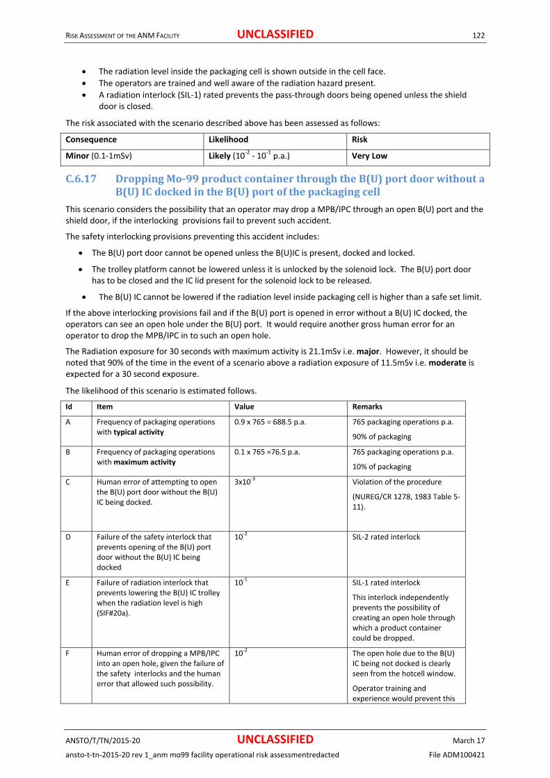
RISK ASSESSMENT OF THE ANM FACILITY UNCLASSIFIED 122
ANSTO/T/TN/2015‐20 UNCLASSIFIED March 17
ansto‐t‐tn‐2015‐20 rev 1_anm mo99 facility operational risk assessmentredacted File ADM100421
The radiation level inside the packaging cell is shown outside in the cell face.
The operators are trained and well aware of the radiation hazard present.
A radiation interlock (SIL‐1) rated prevents the pass‐through doors being opened unless the shield door is closed.
The risk associated with the scenario described above has been assessed as follows:
Consequence Likelihood Risk
Minor (0.1‐1mSv) Likely (10‐2 ‐ 10‐1 p.a.) Very Low
C.6.17 DroppingMo‐99productcontainerthroughtheB(U)portdoorwithoutaB(U)ICdockedintheB(U)portofthepackagingcell
This scenario considers the possibility that an operator may drop a MPB/IPC through an open B(U) port and the shield door, if the interlocking provisions fail to prevent such accident.
The safety interlocking provisions preventing this accident includes:
The B(U) port door cannot be opened unless the B(U)IC is present, docked and locked.
The trolley platform cannot be lowered unless it is unlocked by the solenoid lock. The B(U) port door has to be closed and the IC lid present for the solenoid lock to be released.
The B(U) IC cannot be lowered if the radiation level inside packaging cell is higher than a safe set limit.
If the above interlocking provisions fail and if the B(U) port is opened in error without a B(U) IC docked, the operators can see an open hole under the B(U) port. It would require another gross human error for an operator to drop the MPB/IPC in to such an open hole.
The Radiation exposure for 30 seconds with maximum activity is 21.1mSv i.e. major. However, it should be noted that 90% of the time in the event of a scenario above a radiation exposure of 11.5mSv i.e. moderate is expected for a 30 second exposure.
The likelihood of this scenario is estimated follows.
Id Item Value Remarks
A Frequency of packaging operations with typical activity
0.9 x 765 = 688.5 p.a. 765 packaging operations p.a.
90% of packaging
B Frequency of packaging operations with maximum activity
0.1 x 765 =76.5 p.a. 765 packaging operations p.a.
10% of packaging
C Human error of attempting to open the B(U) port door without the B(U) IC being docked.
3x10‐3 Violation of the procedure
(NUREG/CR 1278, 1983 Table 5‐11).
D Failure of the safety interlock that prevents opening of the B(U) port door without the B(U) IC being docked
10‐2 SIL‐2 rated interlock
E Failure of radiation interlock that prevents lowering the B(U) IC trolley when the radiation level is high (SIF#20a).
10‐1 SIL‐1 rated interlock
This interlock independently prevents the possibility of creating an open hole through which a product container could be dropped.
F Human error of dropping a MPB/IPC into an open hole, given the failure of the safety interlocks and the human error that allowed such possibility.
10‐2 The open hole due to the B(U) IC being not docked is clearly seen from the hotcell window.
Operator training and experience would prevent this

RISK ASSESSMENT OF THE ANM FACILITY UNCLASSIFIED 123
ANSTO/T/TN/2015‐20 UNCLASSIFIED March 17
ansto‐t‐tn‐2015‐20 rev 1_anm mo99 facility operational risk assessmentredacted File ADM100421
Id Item Value Remarks
human error.
A conservative estimate of human error probability 0.01 used.
G Accident frequency resulting in Moderate radiological consequence (1‐20mSv dose).
10‐2x 10‐1 x 10‐2
= 1 x10‐5
D x E x F
Continuous demand
H Accident frequency resulting in Major radiological consequence (20‐100mSv dose).
76.5 x 3x10‐3x 10‐2x 10‐2 x 10‐2
= 2.3x10‐6
B x C x D x E X F
The risk associated with the scenario described above has been assessed as follows:
Consequence Likelihood Risk
Moderate (1 ‐ 20mSv) Highly Unlikely (10‐5 ‐ 10‐4 p.a.) Very Low
Major (20 ‐ 100mSv) Extremely Unlikely (10‐6 ‐ 10‐5 p.a.) Low
C.6.18 B(U)ICloadedwithanMPB/IPCisloweredwithoutthelidinplace
If a B(U) IC loaded with an MPB/IPC is lowered without the B(U) IC lid in place, there would be above normal radiation exposure to personnel in the front of cell. It however requires a combination of human error and safety interlock failure.
Above normal radiation exposure to operating personnel at the front of the cell is limited to scattered radiation as the B(U) IC body will still provide shielding. There are multiple radiation monitors in the front of cell area that would provide warning. The radiological consequence is assessed as Minor (0.1‐1mSv) for all product despatches.
Such an accident has a frequency in the range of 10‐2 ‐ 10‐1 p.a. (i.e. Likely) due to the safety interlocking provisions preventing this accident:
The trolley platform cannot be lowered unless it is unlocked by the solenoid lock on the draw latch.
The lid closed sensor should confirm that the lid is closed and the IC lid present sensor should confirm the IC lid is in position before the solenoid lock is released.
The risk associated with the scenario described above has been assessed as follows:
Consequence Likelihood Risk
Minor (0.1‐1mSv) Likely (10‐2 ‐10‐1 p.a.) Low
C.7 UnauthorisedentryofoperatortoaHighradiation/contaminationarea
C.7.1 Unauthorisedentrytobasementarea,groundfloorormezzaninefloorarea
Area radiation monitors are available in various general locations in the basement area, the ground floor and the mezzanine floor (as discussed in Section 4.8) which detect abnormal radiation levels and provide warning to personnel. Detection of abnormal radiation levels help to prevent access into a relatively high radiation area and enable personnel to leave the area and to subsequently investigate the causes of such abnormal radiation.
Any special maintenance work that involves removal of shielding would require Health Physics support in addition to other administrative controls as well the preparation of Safe Work Method and Environmental Statements (SWMES).
Failure of the area radiation monitors under normal operating conditions within the various area would not result in any radiological consequence. But under accident conditions (i.e. radiation or contamination level above radiological area classification) such as the failure of the administrative controls allowing access to

RISK ASSESSMENT OF THE ANM FACILITY UNCLASSIFIED 124
ANSTO/T/TN/2015‐20 UNCLASSIFIED March 17
ansto‐t‐tn‐2015‐20 rev 1_anm mo99 facility operational risk assessmentredacted File ADM100421
prohibited areas, the failure of local are monitoring could result in above normal radiation exposure to personnel. Nevertheless, operators will be wearing EPDs which will alert the operator to above normal levels of radiation, allowing them time to leave the area.
The worst case dose rates are estimated to be around the basement area of 8mSv/h at 5cm (Alam, 2015). Dose rate at 1m distance from the sources of high dose rates is estimated to be in the 0.1‐1mSv/h range. The worst case radiological consequence is assessed as minor 0.5mSv for a 30minutes exposure dose to such high dose rate areas.
Failure of the controls discussed above, it is assumed Very Unlikely (frequency in the range of 10‐4 ‐ 10‐3 p.a.) that an operator will receive
The risk associated with the scenario described above, generally applicable to all areas has been assessed as follows:
Consequence Likelihood Risk
Minor (0.1‐1mSv dose) Very Unlikely (10‐4 ‐ 10‐3 p.a.) Very Low
Recommendation:
R10: Controlled access procedures must be implemented to restrict access to prohibited areas across the Facility. Hazard notice boards and Local rules should be established and displayed
C.7.2 Operatorenterstheliquidwastesamplingcellwhenthereisradioactivityinside
The scenario considered here is the accidental entry of an operator into the liquid waste sampling cell to carry out some maintenance work without ensuring that there is no significant level of radioactivity inside this cell. The necessity for such entry may occur once per year. The radiation monitor in the liquid waste sampling cell provides an indication of the radiation level to the operators. With such warning the human error probability is assessed as unlikely and hence the likelihood is estimated as 3x10‐3 p.a. The radiological consequence of such event is assessed as minor (0.1‐1mSv).
Thus, the risk of radiological consequence is assessed as follows.
Consequence Likelihood Risk
Minor (0.1‐1mSv dose) Unlikely (10‐3 ‐ 10‐2 p.a.) Very Low
C.7.3 Operatorentersliquidwastevalveroomwithoutadequateflushingofthewastepipes
This scenario considers infrequency accidental entry (around 4 p.a.) of an operator to the liquid waste valve room, without first flushing off any residual activity in the waste pipes. The impact to the operator is considered to be minor (0.1‐1mSv). A radiation detector inside the valve room with monitor outside the valve room provides indication and warning to the operators of the radiation hazard present. The probability of failure of the administrative control is assessed as 3x10‐3. Therefore, it is considered Likely (frequency in the range of 10‐2 ‐ 10‐1 p.a.) that an operator will enter the area 4 x 3x10‐3 = 1.2 x 10‐2.
Thus, the risk of radiological consequence is assessed as follows.
Consequence Likelihood Risk
Minor (0.1‐1mSv dose) Likely (10‐2 ‐ 10‐1 p.a.) Low
Recommendation:
R11: Management must implement strict administrative controls, which requires flushing off any residual activity in the waste pipes prior to operator entering the liquid waste valve room.

RISK ASSESSMENT OF THE ANM FACILITY UNCLASSIFIED 125
ANSTO/T/TN/2015‐20 UNCLASSIFIED March 17
ansto‐t‐tn‐2015‐20 rev 1_anm mo99 facility operational risk assessmentredacted File ADM100421
C.7.4 Operatoropensthemaintenanceaccessdoorofthepackagingcellwithoutfirstensuringthatthereisnosignificantradioactivityinsidethecell.
This fault scenario is associated with the accidental opening of the maintenance access door of the packaging cell when the maximum activity is present inside the cell. Such situation could only occur in special cases less than 10% of the time.
The likelihood of accidental radiation exposure to 20‐100mSv (i.e. major) has been assessed as Highly Unlikely (10‐5 – 10‐4 p.a.), taking into account measure to minimise human error associated with this accident (Perera, 2015b).
The infrequency access requirement (twice per annum),
The probability of the presence of maximum activity and
The preventive measure provided by the radiation monitor.
Administrative controls i.e. visual check from the front of cell and communication with operations staff.
Recommendation:
R12: Controlled access procedures must be implemented to restrict access to packaging Cell. Health Physics support will be sought to advise on the estimated potential dose exposure prior to entry. Hazard notice boards and Local rules should be established and displayed
The risk of the above described worst case scenario is assessed as follows.
Consequence Likelihood Risk
Major (20‐100mSv dose) Highly Unlikely (10‐5 ‐ 10‐4 p.a.) Low
In the majority of cases (more than 90% of the time), the activity is limited and the radiological consequence is in the 1‐20mSv range (i.e. moderate). The likelihood of such event is however an order of magnitude higher than the worst case scenario assessed above.
The risk of the scenario is assessed as follows.
Consequence Likelihood Risk
Moderate (1‐20mSv dose) Highly Unlikely (10‐5 ‐ 10‐4 p.a.) Very Low
C.8 FireintheFacilityAn analysis conducted in AECOM 2015b based on the compliance with the NSW and Commonwealth Work Health and Safety Regulation (NSW, 2011), the relevant Australian Standard and the NSW WorkCover Dangerous Goods Code of Practice (CoP).
Based on the results of the assessment, it was concluded that the ANM facility to be designed, built and operated within Lucas Heights complies with the WHS Management System, CoP and relevant Australian Standard applicable to the DG Class stored, with the exception of the separation distances between the storage depots and the on‐site protected places (i.e. adjacent laboratories and work areas).
In addition it was identified that a number of procedures would be required under the provisions of the relevant sections of the Australian Standards and that documentation would be required in order to comply with the relevant sections of Chapter 7 of the WHS Regulation. It was concluded that the required procedures and documentation could be prepared and provided prior to the commencement of operations complying with the requirements of the relevant Australian Standards.
In order to address the points of non‐compliance, an assessment will be made as part of the Dangerous Good Review regarding the storage and handling of Dangerous Goods within the Facility, in particular the separation of ignition sources. The review will include all chemicals to be handled within the Facility.

RISK ASSESSMENT OF THE ANM FACILITY UNCLASSIFIED 126
ANSTO/T/TN/2015‐20 UNCLASSIFIED March 17
ansto‐t‐tn‐2015‐20 rev 1_anm mo99 facility operational risk assessmentredacted File ADM100421
C.8.1 Fireintheloadingbay
There is the potential for a serious fire involving all of the diesel fuel in the truck’s tank to occur in the loading bay when the truck is carrying the transport flask in the loading bay. Such a fire may even be the result of the dropping of the transport flask onto the truck (as discussed in Appendix C.2.1) in which case; the transport flask may already be slightly damaged. However, the HIFAR Probabilistic Safety Assessment (PLG, 1997) found the frequency of a vehicle fire incident of this type to be insignificant.
Other than when the truck is in the loading bay, the fire loading in this area is very low and no other fire is considered credible. Heat detectors provide the automatic fire detection capability. Reliance is placed on manual firefighting on the basis that operators will be present during the most vulnerable time (i.e. when the loaded flask is being lifted off the transport truck) and a fire should be readily detected and fire‐fighting operations commenced immediately using local fire extinguishers. The on‐site Emergency Response team is also available to assist in firefighting operations. Therefore, a fire in the loading bay is assessed as being Extremely Unlikely (frequency in the range of 10‐6 ‐10‐5 p.a.)
Consequently, even if a fire were to occur during the unloading operations, it would be readily detected and fire‐fighting operations commenced immediately. The consequences are therefore considered insignificant (no injuries).
The risk of such scenario is assessed as follows.
Consequence Likelihood Risk
insignificant (no injuries) Extremely Unlikely (10‐6 ‐ 10‐5
p.a.) Very Low
C.8.2 Fireinthecellfacearea
The fire loading in this area is low, consisting of plasticised floor covering and limited amounts of wall and ceiling mounted cabling. Heat detectors provide the automatic fire detection capability. Reliance is placed on manual firefighting on the basis that this area is normally occupied during working hours and a fire should be readily detected and fire‐fighting operations commenced immediately using local fire extinguishers. The on‐site Emergency Response team is also available to assist in firefighting operations. The consequence is considered insignificant (no injuries).
As such, a fire is considered to be unlikely to occur in this area. In addition, a fire of sufficient intensity to threaten the integrity of the hotcells or the building itself is not considered to be credible. The scenario of a fire in the cell face area is therefore assessed as being Very Unlikely (frequency in the range of 10‐4 ‐ 10‐3 p.a.).
The risk associated with the scenario described above, generally applicable to all areas has been assessed as follows:
Consequence Likelihood Risk
Insignificant (no injuries) Very Unlikely (10‐4 ‐ 10‐3 p.a.) Very Low
C.8.3 FireintheActivemaintenancearea
The fire loading in this area is considered to be low, consisting of a painted floor covering; limited amounts of wall and ceiling mounted cabling and general workshop materials. In a separate decontamination area adjacent to the rear of the hotcell area, there is an approved flammable liquids storage cabinet that does not to add significantly to the fire loading.
Smoke detectors provide the automatic fire detection capability. Reliance is placed on manual firefighting, on the basis that this area is normally occupied during working hours and a fire should be readily detected and fire‐fighting operations commenced immediately using local fire extinguishers. The on‐site Emergency Response team is also available to assist in firefighting operations.
A fire in this area is considered to be credible. However, a fire of sufficient intensity to threaten the integrity of the hotcells, filter room or the building itself is not considered to be credible, given the small fire loading present. Any fire that does occur may result in an increase in the leakage rate from the hotcells due to damage

RISK ASSESSMENT OF THE ANM FACILITY UNCLASSIFIED 127
ANSTO/T/TN/2015‐20 UNCLASSIFIED March 17
ansto‐t‐tn‐2015‐20 rev 1_anm mo99 facility operational risk assessmentredacted File ADM100421
to the seals on the rear of the cells. However, this is considered to be insignificant (no injuries) in comparison with their normal leak‐rate.
A fire is also considered Very Unlikely (frequency in the range of 10‐4 ‐10‐3 p.a.) to result in a release from the liquid waste storage tanks. This is on the basis that there is no significant fire loading in the area of the storage tanks and that the tanks themselves are embedded into the building’s concrete floor slab.
The risk of such scenario is assessed as follows.
Consequence Likelihood Risk
insignificant (no injuries) Very Unlikely (10‐4 ‐ 10‐3 p.a.) Very Low
C.8.4 Fireinventilationplantroom
A fire in the ventilation plant room would result in the loss of the ventilation within the ANM Facility only. This will result in the loss of the negative pressure within the hotcells and the subsequent spread of contamination into the cell face and rear of cell area due to leakage from the hotcells. Emergency procedures would then require the evacuation of the building. Since the ventilation plant room only has a medium fire loading, it is not considered credible that any such fire could result in structural damage to either the hotcells or facility itself.
The off‐site radiological consequence of the reference accident of the ANM Mo99 facility has been previously estimated as 0.28mSv (minor) for maximum individual effective dose and the maximum on‐site dose has been estimated as 1.82mSv (moderate), based on night time exposure (Barton, 2014). The radiological consequence in this scenario is conservatively assumed to be the same.
Heat detectors provide the automatic fire detection capability. No automatic fire suppression system is provided, reliance being placed on manual firefighting instead. This room is also normally locked closed and would be only visited occasionally. As such, a fire is unlikely but possible. Furthermore, such a fire would result in the loss of ventilation in the Facility for an extended period of time until alternative arrangements are put into place.
Typically a building fire is around 10‐3 p.a. However, a significant fire inside the hotcells is considered at least an order of magnitude lower in likelihood for the reasons given above. The scenario of a fire in the ventilation plant room is assessed as being Very Unlikely (likelihood of 10‐4 ‐ 10‐3 p.a..
The risks associated with such scenario for members of the public and for on‐site personnel are assessed as follows:
Consequence Likelihood Risk
Minor (20µSv to 300 µSv off‐ site dose to members of the public).
Very Unlikely (10‐4 ‐ 10‐3p.a.) Very Low
Moderate (1‐20mSv dose to personnel on site
Very Unlikely (10‐4 ‐ 10‐3p.a.) Low
C.8.5 Afireinthehotcells
A significant fire in the hotcells could cause an off‐site release of radioactive discharges via the stack discharges. The off‐site radiological consequence of the reference accident of the ANM Mo99 facility has been previously estimated as 0.28mSv (Minor) for maximum individual effective dose and the maximum on‐site dose has been estimated as 1.82mSv (Moderate), based on night time exposure (Barton 2014). The radiological consequence in this scenario is conservatively assumed to be the same.
The following factors were considered in the likelihood assessment.
There are no significant quantities of flammable solids or liquids used or stored inside the hotcells.
Except for the Hydrogen Converter in HCELL (which is fully contained), there are no high temperature sources inside the hotcells which could possibly become a ready source of ignition.
RISK ASSESSMENT OF THE ANM FACILITY UNCLASSIFIED 128
ANSTO/T/TN/2015‐20 UNCLASSIFIED March 17
ansto‐t‐tn‐2015‐20 rev 1_anm mo99 facility operational risk assessmentredacted File ADM100421
There are high temperature alarms on the outlet piping of each of the hotcells which would detect an impending fire early.
Typically a building fire is around 10‐3 p.a. But a likelihood of significant fire inside the hotcells is considered at least an order of magnitude lower Highly Unlikely (frequency in the range of 10‐5 ‐ 10‐4p.a.) for reasons given above.
The risks associated with such scenario for members of the public and for on‐site personnel are assessed as follows:
Consequence Likelihood Risk
Minor (20µSv to 300 µSv off‐ site dose to members of the public).
Highly Unlikely (10‐5 ‐ 10‐4p.a.) Very Low
Moderate (1‐20mSv dose to personnel on site
Highly Unlikely (10‐5 ‐ 10‐4p.a.) Very Low
C.8.6 Afireinthecarboncolumns
A fire in the carbon columns would cause off‐site release of radioactive discharges via the stack. The off‐site radiological consequence of the reference accident of the ANM Mo99 facility has been previously estimated as 0.28mSv (Minor) and the maximum on‐site dose has been estimated as 1.82mSv (Moderate), based on night time exposure (Barton 2014). The radiological consequence in this scenario is conservatively assumed to be the same.
The following factors were considered in the likelihood assessment.
The carbon columns are encased in metal housing and there is no possibility that a building fire could impinge directly on the carbon filters.
Any fire originating in the hotcells would not normally reach the carbon columns as the off‐gas flow to the carbon columns is via the gas decay tanks.
There are high temperature alarms on the outlet piping of each of the hotcells which would detect an impending fire originating in the hotcells early.
On the detection of a building fire, the Red primary exhaust fan capacity is lowered to prevent fanning the fire.
Typically a building fire is around 10‐3 p.a. However, due to the metal‐clad carbon columns, filters and other preventive measures, the likelihood of a fire in the carbon columns is at least an order of magnitude lower, Highly Unlikely (frequency in the range of 10‐5 ‐ 10‐4p.a.).
The risks associated with such scenario for members of the public and for on‐site personnel are assessed as follows:
Consequence Likelihood Risk
Minor (20µSv to 300 µSv off site dose to members of the public).
Highly Unlikely (10‐5 ‐ 10‐4p.a.) Very Low
Moderate (1‐20mSv dose to personnel on site
Highly Unlikely (10‐5 ‐ 10‐4p.a.) Very Low
C.8.7 Afireinthecarbon‐filterbank
A fire in the carbon filter bank would cause off‐site release of radioactive discharges via the stack. The off‐site radiological consequence of the reference accident of the ANM Mo99 facility has been previously estimated as 0.28mSv (Minor) and the maximum on‐site dose has been estimated as 1.82mSv (Moderate), based on night time exposure (Barton 2014). The radiological consequence in this scenario is conservatively assumed to be the same.
The following factors were considered in the likelihood assessment.

RISK ASSESSMENT OF THE ANM FACILITY UNCLASSIFIED 129
ANSTO/T/TN/2015‐20 UNCLASSIFIED March 17
ansto‐t‐tn‐2015‐20 rev 1_anm mo99 facility operational risk assessmentredacted File ADM100421
The carbon filters are encased in metal housing and there is no possibility that a building fire could impinge directly on the carbon filters.
Any fire originating in the hotcells would be prevented from reaching the carbon‐filters by the spark arresters.
There are high temperature alarms on the outlet ducting of each of the hotcells which would detect an impending fire originating in the hotcells early.
Carbon filters have temperature monitors on both inlet and outlet ducts.
On the detection of a building fire, the Red primary exhaust fan capacity is lowered to prevent fanning the fire.
There is a deluge system that could be used manually if required to suppress a fire in the filter room. There is a 200mm step down into the room, which acts as a bund (3.2 m3). The room is drained to a sump, which will collect any deluge water. This sump would then need to be assessed and extracted by Waste Management.
Typically a building fire is around 10‐3 p.a. However, due to the metal‐clad carbon columns, filters and other preventive measures, the likelihood of a fire in the filter banks is at least an order of magnitude lower, Highly Unlikely (frequency in the range of 10‐5 ‐ 10‐4p.a.).
The risks associated with such scenario for members of the public and for on‐site personnel are assessed as follows:
Consequence Likelihood Risk
Minor (20µSv to 300µSv off site dose to members of the public).
Highly Unlikely (10‐5 ‐ 10‐4p.a.) Very Low
Moderate (1‐20mSv dose to personnel on site
Highly Unlikely (10‐5 ‐ 10‐4p.a.) Very Low
C.8.8 FireintheQCLaboratory
The fire loading in the QC Laboratory area is considered low, consisting of a painted floor covering; limited amounts of wall and ceiling mounted cabling and general workshop materials. There is potential for packages containing flammable liquids to be dropped resulting in a flammable liquid spill. The spill may generate sufficient flammable vapours that a flammable atmosphere could occur which may ignite resulting in a pool fire. The laboratory is ventilated to prevent the accumulation of flammable vapours below the LFL and ignition sources are controlled within the operational areas.
Personnel are provided with PPE to protect them against exposure while cleaning up using spill kits located throughout the laboratories. In addition, the laboratories are fitted with smoke detection, fire hose reels and extinguishers. Operators are training in handling of chemicals and operation of fire protection equipment. The on‐site Emergency Response team is also available to assist in firefighting operations.
A fire in this area is considered to be credible. However, a fire of sufficient intensity to threaten the integrity of the other areas such as the hotcells, filter room or the building itself is not considered to be credible, given the small fire loading present. Any fire that does occur may result in chemotoxic fumes. However, this is considered to be minor (first aid maybe required) at worst. A fire is also considered Very Unlikely (frequency in the range of 10‐4 ‐10‐3 p.a.) to result in a release.
The risk of such scenario is assessed as follows.
Consequence Likelihood Risk
insignificant (no injuries) Very Unlikely (10‐4 ‐ 10‐3 p.a.) Very Low
C.8.9 Fire/explosionintheGasCylinderStore
A gas cylinder store will be located on the north western corner of the building. The cylinders will be located in a chain wire mesh caged area, which will be secured by a wire chainmesh gate, to permit entry/exit from the store for the storage and handling of cylinders.
RISK ASSESSMENT OF THE ANM FACILITY UNCLASSIFIED 130
ANSTO/T/TN/2015‐20 UNCLASSIFIED March 17
ansto‐t‐tn‐2015‐20 rev 1_anm mo99 facility operational risk assessmentredacted File ADM100421
C.8.9.1 RocketingCylinder(Unloading)
In the event that a cylinder valve stem is damaged (dropped cylinder) during unloading, gas may be released at high pressure which would result in the cylinder being projected at considerable velocity which if a collision between the cylinder and personnel occurs could result in an injury requiring medical attention (moderate).
The cylinders are delivered to site in a stillage which is transported from the delivery vehicle to the storage by a forklift. Furthermore, the cylinders are fitted with valve cap protection. Hence, it is Very Unlikely (frequency in the range of 10‐4 ‐ 10‐3 p.a.) that a cylinder would fall over, and if it did, it is unlikely the valve stem would be damaged as it is protected by a cap.
The risk of such scenario is assessed as follows.
Consequence Likelihood Risk
moderate (Injuries requiring medical attention)
Very Unlikely (10‐4 ‐ 10‐3 p.a.) Low
C.8.9.2 RocketingCylinder(Storage)
In the event that a cylinder valve stem is damaged (dropped cylinder) by a falling cylinder in the storage, gas may be released at high pressure which would result in the cylinder being projected at considerable velocity which if a collision between the cylinder and personnel occurs could result in an injury requiring medical attention (moderate).
The cylinders are stored in brackets in the gas storage area which are secured in position with a chain link restraint. Therefore, the potential for a cylinder to fall and damage the valve stem resulting in a rocketing cylinder is Highly Unlikely (frequency in the range of 10‐5 ‐ 10‐4 p.a.).
The risk of such scenario is assessed as follows.
Consequence Likelihood Risk
moderate (Injuries requiring medical attention)
Highly Unlikely (10‐5 ‐ 10‐4 p.a.) Low
C.8.9.3 RocketingCylinder(Transport)
In the event that a cylinder valve stem is damaged (dropped cylinder) by a falling cylinder during transport, gas may be released at high pressure which would result in the cylinder being projected at considerable velocity which if a collision between the cylinder and personnel occurs could result in an injury requiring medical attention (moderate).
The cylinders are transported in the facility by a trolley which is fixed with brackets and chain link restraints to prevent the cylinders from becoming dislodged during transport. Therefore, the potential for a cylinder to fall and damage the valve stem resulting in a rocketing cylinder is Highly Unlikely (frequency in the range of 10‐5 ‐ 10‐4 p.a.).
The risk of such scenario is assessed as follows.
Consequence Likelihood Risk
moderate (Injuries requiring medical attention)
Highly Unlikely (10‐5 ‐ 10‐4 p.a.) Low
C.8.9.4 Ignition
A gas cylinder store will be located on the north western corner of the building. The cylinders will be located in a chainlink mesh caged area, which will be secured by a chainlink mesh gate, to permit entry/exit from the store for the storage and handling of cylinders.
In the event of a flammable gas release (P10), there is the potential that the release could ignite resulting in a flash fire, jet fire, or explosion in the storage. As the area is unoccupied, physical injury to personnel is not

RISK ASSESSMENT OF THE ANM FACILITY UNCLASSIFIED 131
ANSTO/T/TN/2015‐20 UNCLASSIFIED March 17
ansto‐t‐tn‐2015‐20 rev 1_anm mo99 facility operational risk assessmentredacted File ADM100421
considered credible due to a fire. Nevertheless, a fire leading to an explosion could cause serious injury to persons in the adjacent buildings, resulting in serious injury (major). The gas storage area is located in the open and is naturally ventilated to reduce any flammable gas concentrations below the lower flammability limit (LFL). There are no power points inside the mesh caged area and no credible sources of ignition. Furthermore, the ignition sources in the store are controlled and the cylinder storage is outside the bush fire zone. Therefore, the potential for ignition is considered to be Very Unlikely (frequency in the range of 10‐4 ‐ 10‐3 p.a.).
The risk of such scenario is assessed as follows.
Consequence Likelihood Risk
Major (Serious Injury) Very Unlikely (10‐4 ‐ 10‐3 p.a.)
Medium
With the existing standard safety precautions regarding the use of Gas cylinders across ANSTO, this risk is considered as low as reasonably practicable (ALARP).
C.8.9.5 OxygenDepletion
It was identified that if the contents of a nitrogen cylinder were released in an enclosed area there is the potential that oxygen could be excluded from the room resulting in oxygen deficiency. If personnel entered the oxygen deficient room they may become light headed or lose consciousness within the room.
The cylinders are stored in an area which is open to the outside air and is naturally ventilated, therefore there is no potential for oxygen to be excluded from the space in the event of a release and hence, the area will not be oxygen deficient.
The risk of such scenario is assessed as follows.
Consequence Likelihood Risk
Negligible (Injuries requiring medical attention)
Very Unlikely (10‐4 ‐ 10‐3 p.a.) Low
C.8.10 Fireorbushfiresmoke,embersorheatcausesinjury
Fire or bushfire smoke, embers or heat causes damage to facility or injury e.g. smoke.
Inhalation Bushfires have occurred in the LHSTC area. The ANM facility is near the site perimeter fence in a woodland area. The facility could be affected by smoke and embers and possibly heat from a bushfire. Potential effects include disruption to operations, damage to the building and structures and smoke contamination of air intakes.
In practice a bushfire will not present an immediate risk within the facility. There will be time to safely shut down operations leaving the radioactive materials safely contained. A fire within the building may cause damage to equipment including safety instrumentation.
A fire is unlikely to cause a release of active material or damage the shielded enclosures protecting staff from radiation dose. The process fluids will be aqueous with the exception of small amounts of hydrogen which will be removed by the hydrogen converter. Most equipment inside the process cells will be non‐combustible. There will be some polypropylene bottles and lines in the purification hotcell but there are no ignition sources in this cell.
The main radioactive inventories will be within shielded walls which will provide insulation against the effects of fire and there will be minimal combustible materials in proximity to these inventories. There will be potential for fires to cause smoke inhalation injuries. The risk of smoke inhalation to personnel from an offsite fire (bush fire) is assessed as having a consequence of minor (requiring first aid medical attention). The likelihood of fire or bush fire smoke due to the presence of woodland is Very Likely (frequency in the range of 0.1 p.a. to 1 p.a.).
Consequence Likelihood Risk
Minor (injury). Very Likely (0.1 to 1 p.a.) Low

RISK ASSESSMENT OF THE ANM FACILITY UNCLASSIFIED 132
ANSTO/T/TN/2015‐20 UNCLASSIFIED March 17
ansto‐t‐tn‐2015‐20 rev 1_anm mo99 facility operational risk assessmentredacted File ADM100421
C.9 Hydrogenfireorexplosionfast
C.9.1 Hydrogenfireorexplosioninsidehotcellcontainment
The scenario described above in section C.4.2 considered release of fission gases and hydrogen into the hotcell containment resulting from the rupture of process containment vessels or damage to seals.
This section considers the possibility of a hydrogen fire or explosion inside hotcell containment. Even if there is a large release of hydrogen into the cell, a hydrogen explosion is considered incredible due to the following reasons and quantitatively estimated in the process containment Regulation 54 submission (Perera, 2015a).
A large release of hydrogen into the cell due to over‐pressurisation and rupture of dissolver vessel or damaged seals is assessed as extremely unlikely as stated in C.4.2 above.
The Red primary exhaust of AVS extracts air at 5 air changes per hour from cell volume of 14.6m3, thus any significant release of hydrogen into the cell is most likely to be extracted without the formation of an explosive hydrogen/air mix;
There is no ready source of heat or electrical spark inside the cell containment that could become a source of ignition except the possibility of static electricity build up in the lead glass windows.
The likelihood of hydrogen explosion in the hotcell has been estimated as 1.35 x 10‐7 p.a. i.e. incredible (<10‐6) (Perera, 2015c). Because the accident is considered incredible, the event is not considered any further.
C.9.2 HydrogenfireorexplosionintheAVSexhaustducts
Two possibilities of hydrogen fire or explosion in the AVS ducts were identified in the Regulatory 54 assessment for the ANM AVS system (Perera, 2015).
Hydrogen fire /explosion in the AVS exhaust ducts as a consequence of large release of hydrogen and fission gases into hotcell containment due to the rupture of process containment vessels or damage to seals.
An explosive mix of hydrogen and air in the AVS exhaust ducts during the discharge of off‐gas due to hydrogen conversion failure.
The former case is an extension of the same scenario described in section C.9.1, which was assessed as not credible. The following additional control and mitigation measures apply.
Hydrogen detection in the AVS exhaust duct of the dissolution cell causes the dissolution reaction to slow down.
AVS ducts and metallic and are earthed. There are no foreseen ignition sources in the AVS ducts.
The latter case is considered in subsection below.
C.9.2.1 AnexplosivemixofhydrogenandairintheAVSexhaustductsduetohydrogenconversionfailure.
The possibility of an explosive mix of hydrogen and air in the AVS exhaust ducts due to hydrogen conversion failure was identified in the FMEA. This would require failure of the hydrogen conversion and hence the accumulation of hydrogen in the gas decay tank along with fission gases. The possibility of a fire explosion in the AVS ducts is assessed as Highly Unlikely due to the following reasons.
The control system ensures that the hydrogen converter used for dissolution is adequately regenerated prior to it being used in a dissolution run.
The control system ensures that the hydrogen converter temperature is at least 200°C before dissolution can commence.
Once the dissolution reaction commences the temperature of hydrogen converter is maintained by the exothermic reaction even if the heaters fail.
The failure of hydrogen conversion is detected by the monitoring of temperature and pressure during a dissolution run and also by the above normal rate of pressure build up. The temperatures and flows are recorded in the batch sheets. Thus accumulation of hydrogen in the gas tank is a very unlikely failure, and it will be revealed by the process indications and batch records.

RISK ASSESSMENT OF THE ANM FACILITY UNCLASSIFIED 133
ANSTO/T/TN/2015‐20 UNCLASSIFIED March 17
ansto‐t‐tn‐2015‐20 rev 1_anm mo99 facility operational risk assessmentredacted File ADM100421
The discharge of a gas tank containing hydrogen will involve massive dilution as hydrogen gas enters the duct, which would prevent the formation of an explosive mix.
Damage to AVS ducts would cause air borne contamination in the basement area, which is unmanned. Air samplers provide warning of any air borne contamination in other occupied area which would allow personnel to evacuate the area.
The radiological consequence of this scenario would be equivalent to complete failure of the Red primary exhaust of AVS during normal operation of the facility i.e. negligible dose to personnel (< 0.1mSv) (Section C.5.2). However the consequence in‐terms of legal/regulatory compliance would be moderate due to the possibility of an investigation and major administrative complaint by ARPANSA following a hydrogen explosion in the AVS ducts.
The risk of this scenario is assessed as follows.
Consequence Likelihood Risk
Negligible (dose to operators <0.1mSv)
Highly Unlikely (<10‐5 ‐10‐4p.a.) Very Low
Moderate (Major administrative complaint )
Highly Unlikely (<10‐5 ‐10‐4p.a.) Very Low
C.9.2.2 Entryofairintoprocesscontainmentduringdissolutionandpossibleexplosioninsideprocesscontainment
Hydrogen explosion inside the process containment would require a significant leak of air into the process containment during dissolution to form an explosive mix of hydrogen and air, as well as the existence of an ignition source inside process containment.
The heated bed in the hydrogen converter is considered as a possible ignition source, but only if its temperature is allowed to exceed the auto‐ignition temperature of hydrogen around 550‐580°C.
The hydrogen converter has three band heaters each of which has two thermocouples for control and protection against overheating. The hydrogen converter temperature is monitored, well noted, and recorded in the batch records during a dissolution run.
The likelihood of this scenario is estimated as 2.8x10‐8 p.a. i.e. Incredible, within Appendix B of the Process Containment assessment (Perera, 2015a).
Because the accident is considered incredible, the event is not considered any further.
C.10 DamagetoPlantequipmentasaresultofaSeismicevent
C.10.1 Damagetoprocesstanksorpipingduetoaseismicevent
The process tanks could topple or piping could get damaged in a severe seismic event. The process tanks are bolted to the hotcell containment. Flexible piping is used to connect the tanks to the pipe manifolds which are attached to the hotcell containment.
The process containment is designed to meet SL‐2 requirements for seismic loading (i.e. Highly Unlikely (frequency in the range of 10‐5 ‐ 10‐4 p.a.)
The effect of damage to process containment due to seismic event is the release of fission gases and hydrogen into the hotcell containment, which could also be damaged/ degraded.
This event could result in the release of radioactivity into the hotcell containment as well as outside containment into the building.
The consequences failure of both the ventilation and process containment leads to a moderate dose of 1‐20mSv (Section C.5.3), on the basis of 5 minutes of exposure to airborne contamination. This has been calculated (Penny, 2014) to be 8.8mSv. That assessment assumed intact containment leaking at its design rate of 0.25% per hour.
In the event of a seismic event which is immediately obvious the inhalation dose due to failure of containment is calculated on the basis of 1 minute exposure.

RISK ASSESSMENT OF THE ANM FACILITY UNCLASSIFIED 134
ANSTO/T/TN/2015‐20 UNCLASSIFIED March 17
ansto‐t‐tn‐2015‐20 rev 1_anm mo99 facility operational risk assessmentredacted File ADM100421
For the seismic failure of process containment with degraded hotcell containment with an assumed leak rate of 10% per hour (degraded hotcell containment) , the inhalation dose for 1 minute of exposure is estimated as 8.8 x (10/0.25) x (1/5) = 72.4mSv, i.e. major (20‐100mSv dose). Off‐site radiological consequence is assumed to be minor.
The consequence in terms of legal compliance could be moderate as it would involve ARPANSA investigation and administrative complaint.
The risks of this scenario are assessed as follows.
Consequence Likelihood Risk
Minor (20‐300µSv dose off site) Highly Unlikely (10‐5 ‐ 10‐4 p.a.) Very Low
Major (20‐100mSv dose to operators).
Highly Unlikely (10‐5 ‐ 10‐4 p.a.) Low
Moderate( Major administrative complaint )
Highly Unlikely (10‐5 ‐ 10‐4 p.a.) Low
C.10.2 SeismicFailureofDecayTanks
For intermediate level liquid waste to enter the ground water would require a failure of both the tank and the bunker. The only credible failure mode identified is a beyond‐design‐basis earthquake. The plant has been designed to SL‐2, therefore the likelihood of an earthquake leading to a leak into the ground water has been assessed as Highly Unlikely (10‐5 ‐ 10‐4 p.a.).
Dose to operators from such a scenario is expected to be less than statutory limits (i.e. moderate dose between 1 and 20 mSv). No significant off‐site exposure is expected, as the liquid will not contain volatile radionuclides and the chemistry is such that no radioactive gases will be evolved. The environmental consequences would require significant effort to remediate, but would be contained to the buffer zone. Estimates of ground water velocities based on ANSTO’s monitoring program [ANSTO, 2007] range from 0.02 to 7.36 metres per year. At the highest rate, it would take approximately 12 years to leave the fenced area, and hundreds of years to leave the site exclusion zone. Within these time frames, remediation would be achievable.
The risk to operators associated with the seismic failure of the liquid waste decay tanks and bunker has been assessed as follows:
Consequence Likelihood Risk
Moderate (1‐20mSv). Highly Unlikely (10‐5 ‐ 10‐4 pa) Very Low
The risk to the environment associated with the seismic failure of the liquid waste decay tanks and bunker has been assessed as follows:
Consequence Likelihood Risk
Major (Medium term damage confined to buffer zone).
Highly Unlikely (10‐5 ‐ 10‐4 pa) Low
C.10.3 SeismicFailureoftheLiquidWasteHoldingTanks
The only credible accident resulting in failure of both the liquid waste holding tanks and bund is a beyond design basis earthquake. The plant has been designed to SL‐2, therefore the likelihood of an earthquake leading to a leak into the ground water has been assessed as Highly Unlikely (10‐5 ‐ 10‐4 p.a.)
The potential consequences of this event are bounded by the seismic failure of the liquid waste decay tanks (which hold approximately 6500L compared with 290L in the holding tanks).
The risk to operators associated with the seismic failure of the liquid waste decay tanks and bunker has been assessed as follows:

RISK ASSESSMENT OF THE ANM FACILITY UNCLASSIFIED 135
ANSTO/T/TN/2015‐20 UNCLASSIFIED March 17
ansto‐t‐tn‐2015‐20 rev 1_anm mo99 facility operational risk assessmentredacted File ADM100421
Consequence Likelihood Risk
Moderate (1‐20mSv). Highly Unlikely (10‐5 ‐ 10‐4 pa) Very Low
The risk to the environment associated with the seismic failure of the liquid waste holding tanks and bund has been assessed as follows:
Consequence Likelihood Risk
Major (Medium term damage confined to buffer zone).
Highly Unlikely (10‐5 ‐ 10‐4 pa) Low
C.11 CriticalityIncidentsIn the Mo‐99 production process, approximately 2% of the U‐235 in the target is fissioned during irradiation. During the target dissolution step, the remaining 98% of U‐235 and U‐238 will be retained on the SUF cup in the form of a mixture of uranium dioxide and sodium diuranate with fission products insoluble in solution. These SUF cups will be stored initially in purpose designed compartments in the dissolution cells to allow decay. After a decay period, the SUF cups will be moved by PADIRAC to the solid waste hotcell. From here the cups will be removed from the facility in the SUF flask to Waste Operations control. The number of SUF cups at any time in the facility will be limited. The U‐235 will be in a form that minimises the risk of criticality incidents. Firstly it will be a LEU isotopic mix. Further it will be retained as small amounts on discrete SUF cups of comparatively much larger volume.
In addition there will be safety controls:
Careful design of the geometry of the storage compartments.
Careful accounting methods controlling the inventory.
Criticality certificates approving the storages will be prepared by the ANSTO Nuclear Analysis Section.
A trace amount of uranium passes through the SUF and enters the liquid waste. This does not present a nuclear hazard. Given the inherent safety of the form of the fissile material, the relatively small total amount of fissile material, and the controls, the likelihood of a criticality accident is considered incredible <10‐6 p.a..
Because the accident is considered incredible, the event is not considered any further.
C.12 Industrialhazards
C.12.1 Accidentalcontactwithelectricalterminals
Electrocution and/or electric shock due to accidental contact of electrical terminals by maintenance personnel is Highly Unlikely, but still a credible accident. This is a risk that is a common to all facilities in ANSTO. Standard ANSTO systems and procedures for working with electrical systems will apply. These include isolation, earthing, tagging, and compliance with AS3000. Residual current protection is available in power outlets. Standard ANSTO practice (followed in the ANM Facility) involves the use of such protection in special circumstances such as temporary wiring for repair works etc.
The risk associated with the scenario described above has been assessed as follows:
Consequence Likelihood Risk
Severe (Fatality or permanent injury )
Highly Unlikely (10‐5‐10‐4 p.a.) Medium
With the existing standard safety precautions against electrical shock hazards, this risk is considered as low as reasonably practicable (ALARP).
C.12.2 Workerfallingduringmaintenanceandoperations
Maintenance and operations personnel may be required to working around the access hatch, carbon column, and valve room plus other areas to perform certain tasks. Appropriate safety precautions in line with ANSTO

RISK ASSESSMENT OF THE ANM FACILITY UNCLASSIFIED 136
ANSTO/T/TN/2015‐20 UNCLASSIFIED March 17
ansto‐t‐tn‐2015‐20 rev 1_anm mo99 facility operational risk assessmentredacted File ADM100421
WHS Management System are expected to be taken. These include the following measures where applicable, depending on the work to be undertaken.
Risk assessment of the work including the preparation of a safe work method statement (SWMS).
Use of ladders complying with Australian Standards and WHS Management System.
Use of fall arrest systems where necessary.
Use of scaffolding as required.
Use of scissor lifts if deemed appropriate (during manipulator maintenance for example).
The consequence of a fall injury is assessed as (serious injury).
The risk associated with the scenario described above has been assessed as follows:
Consequence Likelihood Risk
Major (Long term injury but recovery probable )
Very Unlikely (10‐4‐10‐3 p.a.) Medium
With the existing safety precautions, this risk is considered as low as reasonably practicable (ALARP).
C.12.3 InjuryDuetoSlip,TriporFallingeneralareas
An injury due to a slip, trip and fall could cause a lost time injury. The following controls apply.
Operator training and experience; and
Good housekeeping.
The potential for injury due to slip, trip and falling general area around the Facility cannot be totally dismissed in the work place. A WHS risk assessment will be undertaken to ensure that appropriate measures are in place within the Facility. The likelihood is assessed to be in the range 10‐3 ‐ 10‐2 per year (Unlikely). With Moderate consequence (lost time injury).
The risk associated with the scenario described above has been assessed as follows:
Consequence Likelihood Risk
Moderate (lost time injury) Unlikely (10‐3 ‐ 10‐2 pa) Low
C.12.4 Manualhandlingaccident
A manual handling injury could occur during operation within the ANM. A human Factors study has been undertaken of operations to be taken within the ANM Facility, to minimise the potential for manual handling injury and to ensure that design of the facility is ergonomically sound. The operations within ANM facility are Unlikely (frequency in the range of 10‐3 ‐ 10‐2 per year) to cause a moderate consequence (lost time injury); the following controls and mitigation measures apply.
Operator training and experience,
Good ergonomic design, and
Well‐written recovery procedures.
The risk associated with the scenario described above has been assessed as follows:
Consequence Likelihood Risk
Moderate (Medical attention or several lost time days)
Unlikely (10‐3 ‐ 10‐2 pa) Low
RISK ASSESSMENT OF THE ANM FACILITY UNCLASSIFIED 137
ANSTO/T/TN/2015‐20 UNCLASSIFIED March 17
ansto‐t‐tn‐2015‐20 rev 1_anm mo99 facility operational risk assessmentredacted File ADM100421
APPENDIXD‐CONSEQUENCEASSESSMENTOFANUNSPECIFIEDENERGETICEVENT
D.1 IntroductionAs part of the siting licence application for the ANM Mo99 facility, ANSTO submitted a reference accident analysis document (Ellis, Turner, Barton and Watts, 2013) for the purposes of demonstrating the site was suitable for the concept facility.
The reference accident scenario was a severe earthquake causing damage to the pipework to the gas storage tanks, releasing the full inventory of gas from two dissolver runs. This event was considered a bounding credible accident.
In his statement of reasons document (Larrson, 2013) in relation to the granting of the siting licence, the CEO ARPANSA stated that he expected further analysis of accident scenarios, involving a range of potential scenarios and mitigation and that he expects these analyses to be performed in consultation with ARPANSA staff.
ANSTO has developed accident scenarios in this Operations Safety Assessment document submitted as part of the Operations licence application. A more generic event has been considered for the purposes of future emergency planning and preparedness. This event has been termed an “unspecified energetic event” for the purposes of this analysis.
D.2 AnalysismethodologyA brief summary of the analysis methodology and the assumptions used is given below.
D.2.1 GenericAssumptionsThe computer package PC‐Cosyma (Version 2) has been used to estimate doses due to accidental airborne releases. For a full description of this model, please see EUR 16239 (Jones et al, 1996). Two calculations were performed, one reflecting day conditions, which would produce the most significant on‐site consequences, and the other night conditions, giving the worst consequences to off‐site receptors.
The calculations performed were deterministic, with the only end point being the long‐term (50‐year integrated) dose to an individual adult. The pathways considered for this calculation were cloud‐shine, ground‐shine, inhalation, re‐suspension and direct skin contamination (ingestion was not included in the preliminary assessment).
The weather conditions applicable are “D” stability category with a wind speed of 3 m/s (to reflect average daytime conditions) and “F” stability category with a wind speed of 1 m/s (to reflect the most conservative night‐time conditions). The measurement height of the wind speed was set at 10 m (PC‐Cosyma automatically adjusts the actual wind speed to account for differences with height). Default values were used for all plume shape parameters. These assumptions are the same as those used for the Siting Safety Assessment of the Reference Accident (ANSTO, 1999).
The appropriate value for the surface roughness length for the LHSTC site is 1m as identified in (Bastin and Barton, 1999). This is equivalent to the PC‐Cosyma surface roughness category “rough” (Jones et al, 1996). Similarly, deposition velocities used were set at 10‐2m/s for elemental iodine, 10‐3m/s for other particulates, and 10‐5m/s for organically bound iodine (Bastin and Barton, 1999).
For the day release scenario, it was considered that there should be no account taken for any shielding (the person would be standing outside in the open for the duration of the scenario). For the night release, it was considered appropriate to take into consideration the much greater likelihood of people being indoors. The shielding values chosen are the same as those quoted in the assessment of releases from HIFAR (Hambley, 1997) for normal activity, and are listed below:

RISK ASSESSMENT OF THE ANM FACILITY UNCLASSIFIED 138
ANSTO/T/TN/2015‐20 UNCLASSIFIED March 17
ansto‐t‐tn‐2015‐20 rev 1_anm mo99 facility operational risk assessmentredacted File ADM100421
Pathway Shielding factor
Cloudshine 0.43
Groundshine 0.33
Inhalation 0.81
Resuspension 0.81
Skin contamination 0.81
D.2.2 ANMMo99SourcetermandbuildingspecificassumptionsConservatively the release height assumed was ground level. The scenario is defined as the following:
The initiating event is some undescribed energetic event that causes massive damage to the dissolver(s);
The inventory of two dissolvers is assumed to be affected;
A rapid release of radionuclides into the atmosphere occurs at ground level.
The following source term assumptions are made:
100% of the fission product gases are made available into the building atmosphere;
1% of the iodine is in volatile form and 100% of this is released into the building atmosphere;
5% of the dissolved or suspended solids (including the 99% radioiodine is present as a solid) are atomised or otherwise made airborne into the building atmosphere in particulate respirable form;
This total inventory is recorded in the table below (that is, the inventory column of the table shows 100% of the noble gases present, 5.95% of radioiodine, and 5% of solids).
The building structure is compromised but largely intact and 80% of the particulates (including non‐volatile radioiodine) in the building atmosphere are retained on building inner surfaces.
This gives the release fractions recorded in the table below.
The inventory used in PC‐Cosyma is provided in Barton, 2014. The composition and magnitude of the source term inventory is described in ARPANSA 2014.
D.3 ResultsThe results of the PC‐Cosyma assessment are presented below:
Adult Effective Dose D3 met. Conditions F1 met. Conditions
Receptor Point Effective Dose (mSv) Effective Dose (mSv)
On‐site (250m) 1.8 4.2
Steven’s Hall (1150m) 0.16 0.83
Nearest Resident (1850m) 0.07 0.44
Adult Thyroid Dose D3 met. Conditions F1 met. Conditions
Receptor Point Effective Dose (mSv) Effective Dose (mSv)
On‐site (250m) 10 30
Steven’s Hall (1150m) 0.84 5.9
Nearest Resident (1850m) 0.38 3.2
As PC‐Cosyma does not include child or infant doses, the following results have been scaled from the adult doses, using the age‐related dose conversion factors weighted by nuclide contribution.

RISK ASSESSMENT OF THE ANM FACILITY UNCLASSIFIED 139
ANSTO/T/TN/2015‐20 UNCLASSIFIED March 17
ansto‐t‐tn‐2015‐20 rev 1_anm mo99 facility operational risk assessmentredacted File ADM100421
Child Thyroid Dose D3 met. Conditions F1 met. Conditions
Receptor Point Effective Dose (mSv) Effective Dose (mSv)
On‐site (250m) 19
Steven’s Hall (1150m) 1.6 12
Nearest Resident (1850m) 0.75 6.3
Infant Thyroid Dose D3 met. Conditions F1 met. Conditions
Receptor Point Effective Dose (mSv) Effective Dose (mSv)
On‐site (250m) 28
Steven’s Hall (1150m) 2.4 17
Nearest Resident (1850m) 1.1 9.4
Note that it is not considered credible to have children or infants on‐site during the night, so no dose has been calculated for those cases.
All these consequences are below levels requiring the consideration of intervention (sheltering or provision of stable iodine).
D.4 ReferencesBastin and Barton, 1999, Estimates of Doses from Routine Emissions of Radionuclides to Atmosphere from Lucas Heights Science and Technology Centre During 1997 and 1998, SD/SR/TN99‐11.
Ellis, Turner, Barton and Watts, 2013, ANSTO Nuclear Medicine Mo‐99 Facility Reference Accident Assessment, ANSTO/T/TN/2012‐07 rev 0
Hambley, D.I. 1997. Evaluation of PC‐Cosyma for radiological consequence assessments for HIFAR, Part 1 – Code Comparison, Feb. 1997, NSU/TN/006
Jones et al, 1996, PC‐Cosyma (Version 2): An accident consequence assessment package for use on a PC, 1996 EUR 16239, J.A. Jones, P.A. Mansfield, and S.M. Haywood.
Larsson, 2013, Statement of Reasons: Decision by the CEO of ARPANSA on Facility Licence Application A0270 from the Australian Nuclear Science and Technology Organisation (ANSTO) to Prepare a Site for the ANSTO Nuclear Medicine Molybdenum‐99 Facility, 4 October 2013
Barton 2014, Safety Assessment of the ANM Mo99 Operations, May 2014, ANSTO/T/TN/2013‐12 rev 1
ARPANSA 2014, Additional Radiological Assessment for an Atmospheric Release at ANSTO’s Proposed Mo‐99 Production Facility, Blake Orr, Marcus Grzechnik, Rick Tinker Version 1.0, March 2014

RISK ASSESSMENT OF THE ANM FACILITY UNCLASSIFIED 140
ANSTO/T/TN/2015‐20 UNCLASSIFIED March 17
ansto‐t‐tn‐2015‐20 rev 1_anm mo99 facility operational risk assessmentredacted File ADM100421
APPENDIXE‐RISKMATRIX(RISKEVALUATIONTABLES)
E.1 LikelihoodEvaluationTable

RISK ASSESSMENT OF THE ANM FACILITY UNCLASSIFIED 141
ANSTO/T/TN/2015‐20 UNCLASSIFIED March 17
ansto‐t‐tn‐2015‐20 rev 1_anm mo99 facility operational risk assessmentredacted File ADM100421
E.2 ConsequenceTable

R
A
an
E
ISK ASSESSMENT OF THE A
NSTO/T/TN/2015‐20
nsto‐t‐tn‐2015‐20 rev
E.3 RISKM
ANM FACILITY
v 1_anm mo99 facility
MATRIX(Risk
UNCLASS
UNCLASSy operational risk asse
kEvaluationT
SIFIED
SIFIEDessmentredacted
Table)
142
March 17
File ADM100421