Embed Size (px)
Citation preview

Análise da Implementação de Processos BIM Aplicados
ao Projeto de Estruturas
Analysis of the implementation of BIM processes in the structural
design project
Extended Abstract
Pedro Maria Ramos da Cunha Serra
Orientador: Prof.ª Dra. Alcinia Zita de Almeida Sampaio
Júri
Presidente: Prof. Dr. Luís Manuel Coelho Guerreiro
Orientador: Prof.ª Dra. Alcinia Zita de Almeida Sampaio
Vogal: Prof. Dr. Pedro Guilherme Sampaio Viola
Parreira
Julho 2015

1. Introduction
In the present global economic situation, there is an urgent need to streamline processes in
order to reduce costs and waste and increase productivity. The construction industry has several
limitations that often result in an increase in the projects time and costs [4].
Many of these limitations are not caused by the construction activity, but by the development,
planning and presentation methods used. Based on these facts, solutions must be developed that are
supported by work methodologies that enhance coordination between stakeholders and information
sharing through the use of appropriate software tools.
2. BIM concept
The recent technological progresses in the fields of computers and informatics allowed the easy
manipulation of large quantities of data, with the use of typical and wide spread platforms. This has
made possible the development of Building Information Modeling (BIM). With the goal of analyzing BIM
from its process aspect, building information modelling can be defined as a working methodology in
the AEC industry, which promotes cooperation between stakeholders throughout the project life
cycle, based on the sharing of digital information.
The adoption of BIM practice cannot be restricted to the acquisition of new work tools, it implies,
simultaneously, the introduction of these new capabilities (of the BIM based software) in the current
workflows of the industry. Therefore, the main objective of this project focuses on analyzing the current
work processes in design companies, in order to create guidelines that enhance a correct and effective
BIM implementation. This study involves the learning of BIM-based tools, the identification of constraints
to its full development and the demonstration of its applicability in a practical project [2].
3. BIM process, tools and regulations
The BIM tools are based in the concept of parametric modelling. Parametric modelling is distinct
from the traditional CAD modelling due to its ability to replace graphic elements (such as line or surfaces)
with intelligent objects. The parametric modelling capability enables the BIM process to work around a
single three-dimensional model, comprising all information related to the project. During the different
phases of project development, this model is successively added and reused, creating the center of
information for the building management, throughout its entire life cycle.
In the area of shared information, it is common to distinguish between “the four stages of BIM
which vary between the big BIM and the little BIM and between the individual BIM and the social BIM"
[3]. The social BIM is based on a complete collaborative environment, involving constant exchanges of
standardized and controlled information among all stakeholders. The individual BIM is related to the
processes that occur internally in a company, where there are exchanges of information between
different teams implicated in the project. Big BIM and little BIM differ in the amount of produced and
shared information, whether on internal or social level. Thus, if BIM is used exclusively from a
geometrical perspective, for production of graphic documentation, then the little BIM applies. When the
BIM model is used to explore the basis of information management capabilities, planning, construction
and maintenance, the big BIM is involved [5].
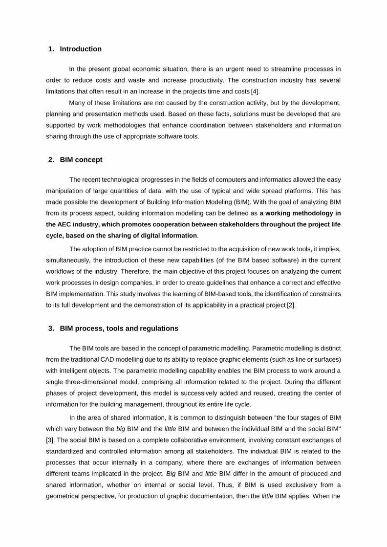
This study focuses on the analysis of a lonely big BIM work methodology (within a design
company) properly structured to be later integrated in a full BIM collaborative environment (level IV).
This methodology is shown in figure 1 and its main feature is presenting how the technical
documentation is produced using the parametric BIM model as the central repository of information.
During the structural design stage, it is necessary to collect all the working elements such as
the owner’s requirements for the structure, the information of the building’s surrounding characteristics
etc. In a BIM environment of level IV, these inputs must be supplied in an electronic form, in order to
automatically verify its compliance with the projects characteristics.
After the pre-design stage, the next step is the development of the parametric model of the
structural solution achieved. Once obtained, the parametric model can be used to automatically create
a FEM model. Both models must share a bidirectional link; expressed through the automatic update of
one model according to the changes occurred in the other. With this, it is possible to maintain the typical
cyclical process of structural design (using the FEM model) and simultaneously update the parametric
model. Sequentially, the parametric model is used for the extraction of drawings, sharing with them a
one-way link that guarantees the constant update of the drawn elements.
As it can be seen, the proposed BIM methodology generates increases in productivity, while
simultaneously improving the quality of the deliverables and the overall project. However, this approach
relies heavily on the technological capabilities of the various software platforms used in the project
company. There are three essential points for a correct application of the proposed BIM workflow:
Bidirectional connection between the parametric model and the finite element model used for
structural calculation;
The one-way link between the parametric model and produced drawings;
The one-way link between the parametric model and the bill of quantities;
In order to analyze the presented workflow, a practical case was developed. Moreover, some of
the existing international regulations were analyzed in order to establish guidelines for the creation of
the parametric model.
Standardization is essential to create the conditions for minimizing the loss of information and
the need for corrections or data re-entry. Additionally, since the final product is a data collection from
various parties, it is required that the manipulated information is consistent in content and level of detail.
Standardization should support the creation and the development of consistent and organized models.
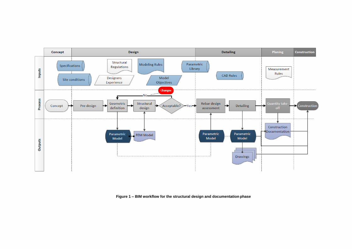
Figure 1 – BIM workflow for the structural design and documentation phase
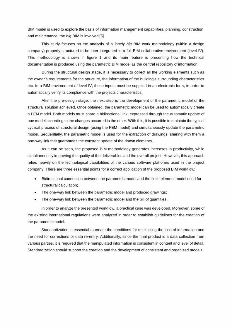
After a proper research, the following three regulations were chosen and analyzed: the National
Common BIM Requirements (COBIM) of Finland, the documents AEC (UK) BIM Strategy and the British
Standards 1192: 2007. Due to their relevance to the current work, a number of modelling rules were
selected from these, regarding the spatial coordination of the model. These are presented in the table
1.
Table 1 – Space coordination rules: regulations and definitions adopted in the practical case
Rules Regulations
Adopted Definition COBIM UK
Length Unit mm mm m:mm2
Accuracy N.A. 2 decimal places 6 decimal places
Angle Unit º N.A. º
Accuracy 2 decimal places N.A. 2 decimal places
XY Positioning Positive area, close to the origin Positive area, close to the origin Positive area, close to
the origin
Elevation Real Real Real
Georeferenced Yes Yes Yes
Model division per
buildings 1 building per model 1 building per model 2 buildings per model
Model division per
floors
Elements divided by floor inside the
same model
Continuous elements, divided only of
necessary
Continuous elements,
divided only of necessary
Model objectives Yes Yes Yes
The analyzed regulations present a wide and diverse collection of good modelling practices to
adopt. Although this aspect strongly depends on the type of software used and the modelling objectives
defined, there are some common rules present in various documents. In consequence, a summary of
some of the most relevant common rules is presented:
Each file should contain only information related to a specialty;
Each building must be delivered in a different model;
The structural model must contain all structural elements, all non-structural concrete elements,
as well as all the products related to structure that affect the remaining elements;
All elements must be modelled with the specific program tool. If not possible, a method
(“workaround”) must be used that should be properly documented;
The modelling should be consistent by being performed in the same way on all objects. If not, it
must be properly documented;
The elements are automatically identified by a Globally Unique Identifier (GUID). For this reason
it is preferable to change objects, instead of replacing them (in order to conserve its GUID);
In the production of technical drawings, the currently used conventions should be kept;
The export of information to a CAD system to be processed, can be performed but should be
avoided, since it reduces the benefits of BIM coordination. Regardless of whether it is decided
to use this approach, the 3D model is developed with the same level of detail that would be
otherwise. This means that the CAD system should be used exclusively as a post-process tool
to enhance the drawings extracted automatically, without adding extra information;
Any recommendations may be replaced with standards set by the owner.
4. Practical case: design stage
The practical project refers to the technical control building of a dam. It includes the offices area,
where the control elements of the dam components are located, and the access to the hydroelectric
sections. The basic information was provided by an engineering consultancy firm, supplied in CAD
format, through the geometric definition drawings of the building.
By working in a level III BIM environment, it is feasible to set goals that the model should be
able to meet internally (to the company). These objectives are related to the traditional outputs of a
structural design such as those represented in the flowchart of figure 1, and are:
Model replication in FEM program for structural calculation;
The extraction of the quantities of materials for planning and budgeting;
The extraction of technical drawings for the execution of the project.
Each of these objectives requires a different level of demand for the modelling process. In order
to fulfil the objective of quantity take-off, it is required for the objects to be modelled without overlapping
and in accordance with the appropriate measurement rules. For the purpose of completing the structural
analysis, it is necessary that the finite element model (extracted from BIM) adapts to the needs of the
software (there is continuity of the structural elements; the relevant information is transmitted, etc.). The
objective regarding the extraction of drawings depends only on the capacity of the software to perform
this task automatically with satisfactory results.
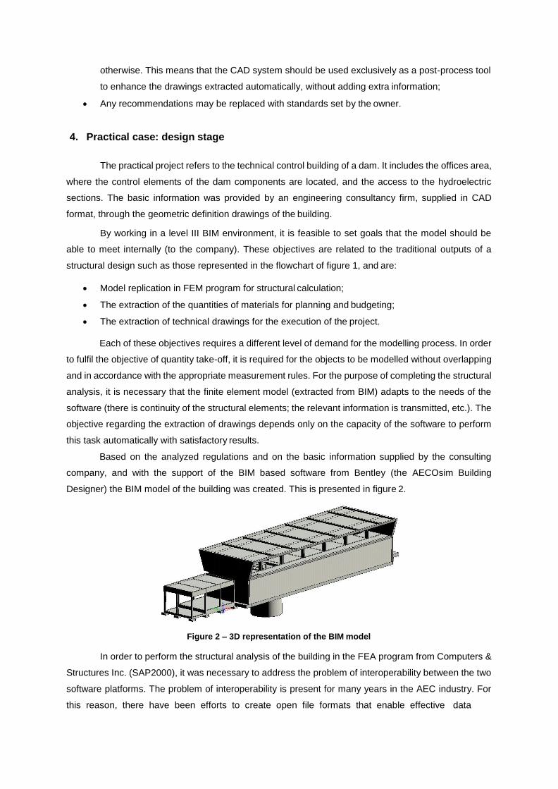
Based on the analyzed regulations and on the basic information supplied by the consulting
company, and with the support of the BIM based software from Bentley (the AECOsim Building
Designer) the BIM model of the building was created. This is presented in figure 2.
Figure 2 – 3D representation of the BIM model
In order to perform the structural analysis of the building in the FEA program from Computers &
Structures Inc. (SAP2000), it was necessary to address the problem of interoperability between the two
software platforms. The problem of interoperability is present for many years in the AEC industry. For
this reason, there have been efforts to create open file formats that enable effective data
exchange between different programs. Some of the most relevant data formats are CimStell Integration
Standard Version 2 (CIS / 2), the Drawing eXchange Format (DXF), the Initial Graphics Exchange
Specification (IGES), the Steel Detail Neutral File (SDNF), or the Structural Analysis and Design Pro
(STAAD). In the BIM area, it has been developed the Industry Foundation Classes (IFC) standard which
aims to establish the connection between all the BIM processes of the structure’s lifecycle.
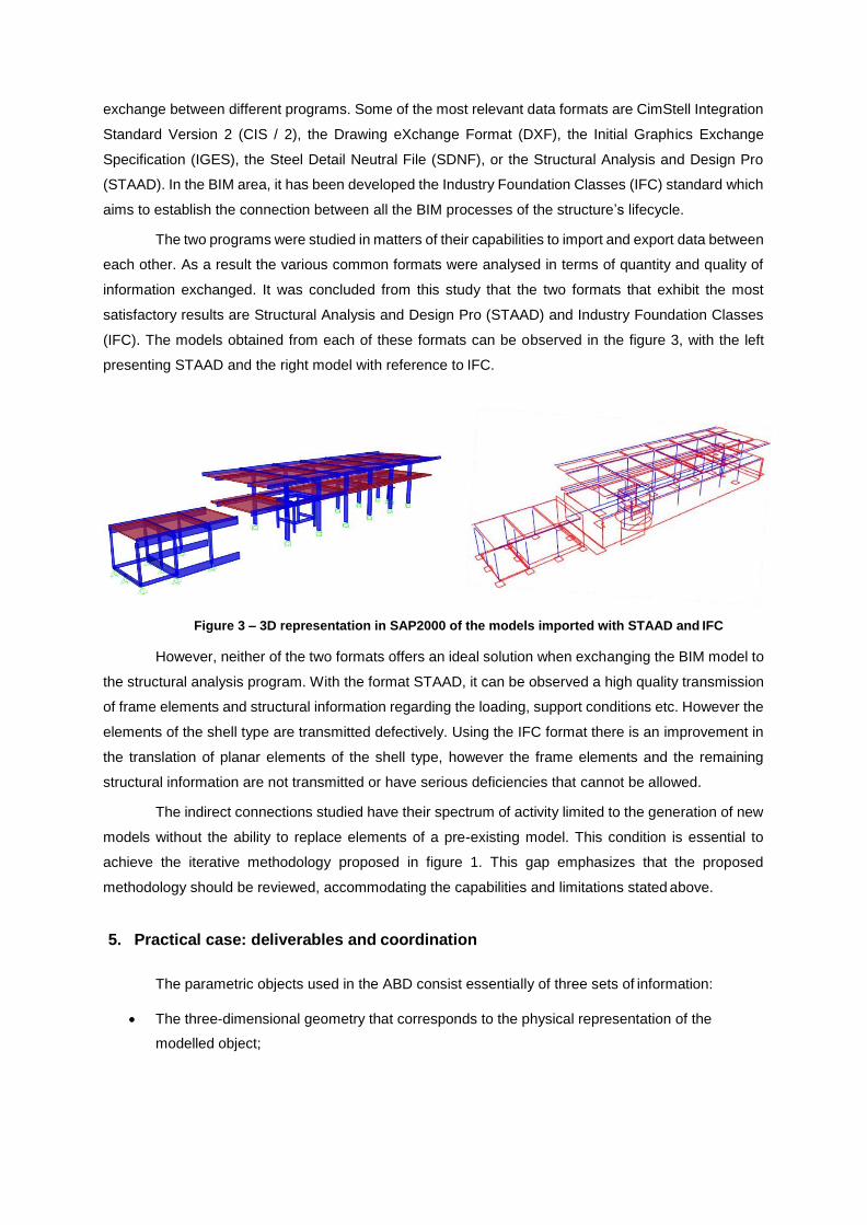
The two programs were studied in matters of their capabilities to import and export data between
each other. As a result the various common formats were analysed in terms of quantity and quality of
information exchanged. It was concluded from this study that the two formats that exhibit the most
satisfactory results are Structural Analysis and Design Pro (STAAD) and Industry Foundation Classes
(IFC). The models obtained from each of these formats can be observed in the figure 3, with the left
presenting STAAD and the right model with reference to IFC.
Figure 3 – 3D representation in SAP2000 of the models imported with STAAD and IFC
However, neither of the two formats offers an ideal solution when exchanging the BIM model to
the structural analysis program. With the format STAAD, it can be observed a high quality transmission
of frame elements and structural information regarding the loading, support conditions etc. However the
elements of the shell type are transmitted defectively. Using the IFC format there is an improvement in
the translation of planar elements of the shell type, however the frame elements and the remaining
structural information are not transmitted or have serious deficiencies that cannot be allowed.
The indirect connections studied have their spectrum of activity limited to the generation of new
models without the ability to replace elements of a pre-existing model. This condition is essential to
achieve the iterative methodology proposed in figure 1. This gap emphasizes that the proposed
methodology should be reviewed, accommodating the capabilities and limitations stated above.
5. Practical case: deliverables and coordination
The parametric objects used in the ABD consist essentially of three sets of information:
The three-dimensional geometry that corresponds to the physical representation of the
modelled object;
Information relating to Family & Parts that contains, among others, the 2D representation rules
of the objects;
Information on the Datagroup, the most relevant properties that allow for the characterization
and quantification of the objects.
After the parametric building model is created, the automatic extraction of drawings can be
performed. 2D representations are essentially defined by the outline of the geometry of the elements.
However, there is a set of rules and other elements, which can also be represented, that do not have a
physical expression in the three-dimensional parametric model. Examples of these elements can be the
axis lines of the pillars or beams, the differentiation of elements based on their position interpreted
though different thicknesses or colors, or the simple differentiation between filling concrete, first phase
concrete, second phase concrete etc. All these elements are defined using the properties Family and
Parts of the ABD parametric objects.
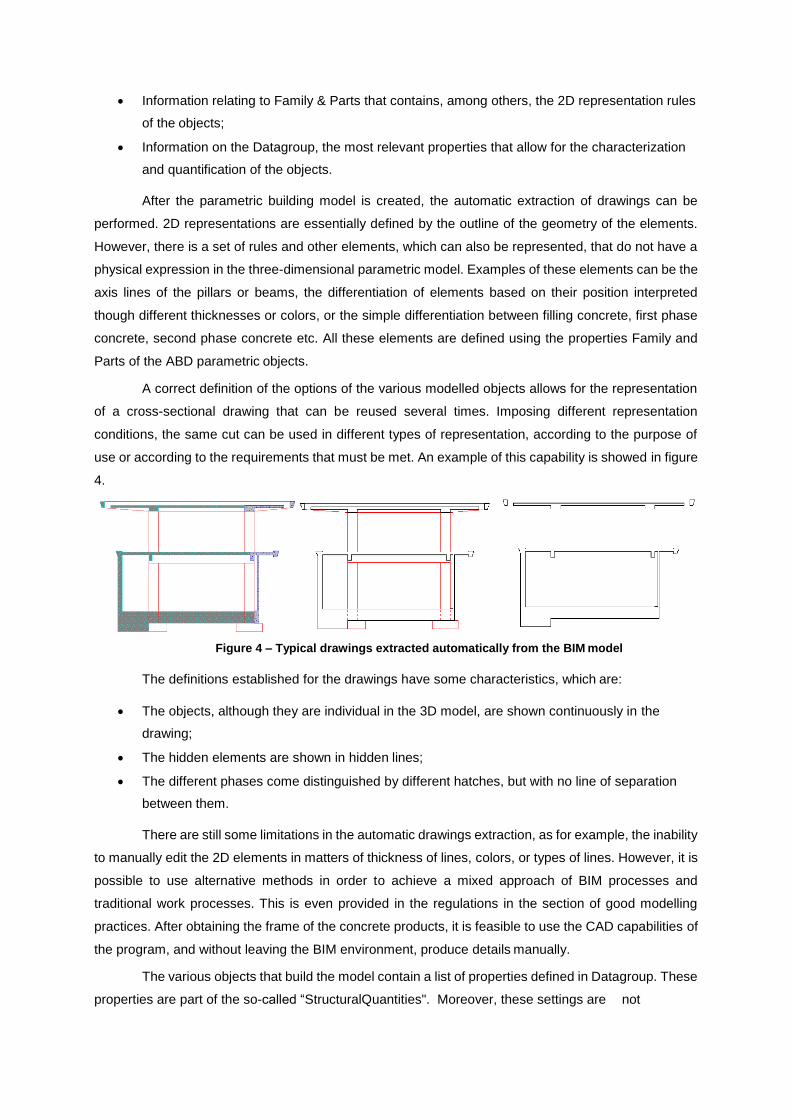
A correct definition of the options of the various modelled objects allows for the representation
of a cross-sectional drawing that can be reused several times. Imposing different representation
conditions, the same cut can be used in different types of representation, according to the purpose of
use or according to the requirements that must be met. An example of this capability is showed in figure
4.
Figure 4 – Typical drawings extracted automatically from the BIM model
The definitions established for the drawings have some characteristics, which are:
The objects, although they are individual in the 3D model, are shown continuously in the
drawing;
The hidden elements are shown in hidden lines;
The different phases come distinguished by different hatches, but with no line of separation
between them.
There are still some limitations in the automatic drawings extraction, as for example, the inability
to manually edit the 2D elements in matters of thickness of lines, colors, or types of lines. However, it is
possible to use alternative methods in order to achieve a mixed approach of BIM processes and
traditional work processes. This is even provided in the regulations in the section of good modelling
practices. After obtaining the frame of the concrete products, it is feasible to use the CAD capabilities of
the program, and without leaving the BIM environment, produce details manually.
The various objects that build the model contain a list of properties defined in Datagroup. These
properties are part of the so-called “StructuralQuantities". Moreover, these settings are not
editable by the user and they are automatically calculated by the program, allowing obtaining volumes,
areas, lengths, etc. The features contained in StructuralQuantities can be automatically extracted from
the program, and exported to an Excel sheet, with a pre-defined template by the user, prepared for
processing information. According to [1] the most appropriate workflow for the extraction of quantities is
the following:
Through the Datagroup Explorer create a list for each type of object used in the model;
Export each list to a separate Excel sheet;
Connect all the sheets to an aggregation file (template) through the property "copy link";
Use this central database for processing information and remove the elements for the
preparation of bills of quantities.
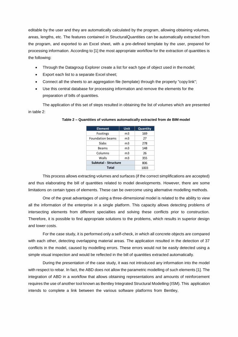
The application of this set of steps resulted in obtaining the list of volumes which are presented
in table 2:
Table 2 – Quantities of volumes automatically extracted from de BIM model
Element Unit Quantity
Footings m3 169
Foundation beams m3 27
Slabs m3 278
Beams m3 148
Columns m3 26
Walls m3 355
Subtotal - Structure 806
Total 1003
This process allows extracting volumes and surfaces (if the correct simplifications are accepted)
and thus elaborating the bill of quantities related to model developments. However, there are some
limitations on certain types of elements. These can be overcome using alternative modelling methods.
One of the great advantages of using a three-dimensional model is related to the ability to view
all the information of the enterprise in a single platform. This capacity allows detecting problems of
intersecting elements from different specialties and solving these conflicts prior to construction.
Therefore, it is possible to find appropriate solutions to the problems, which results in superior design
and lower costs.
For the case study, it is performed only a self-check, in which all concrete objects are compared
with each other, detecting overlapping material areas. The application resulted in the detection of 37
conflicts in the model, caused by modelling errors. These errors would not be easily detected using a
simple visual inspection and would be reflected in the bill of quantities extracted automatically.
During the presentation of the case study, it was not introduced any information into the model
with respect to rebar. In fact, the ABD does not allow the parametric modelling of such elements [1]. The
integration of ABD in a workflow that allows obtaining representations and amounts of reinforcement
requires the use of another tool known as Bentley Integrated Structural Modelling (ISM). This application
intends to complete a link between the various software platforms from Bentley,
enabling the use of the same parametric model to perform finite element analyses or detail the concrete
elements. Using the ISM as a connection, it is possible, for example, to export the parametric model for
the FEM programs from Bentley, perform structural analysis and return the results to ABD. This flow is
identical to what is required to achieve in this work. The advantage of the described process is the
technological capacity, limited in programs from Bentley, which overcomes many of the interoperability
issues that have been identified. Some of the information that the ISM returns to ABD concerns rebar
needs of the elements, calculated by the FEM software. Consecutively, the ABD processes this
information enabling their display in the extracted drawings.
Another workflow made possible by this application involves the export of parametric model for
3D detail program from Bentley, the ProStructures. This software can perform appropriate detailing
(based on information obtained from the FEM analysis), and report automatic drawings and rebar
schedules. None of these options has been the object of study in this dissertation, as these are not part
of the software tools available in the company environment in which the work is part of. However, it can
be said that this type of solutions presents unsatisfactory results with regard to the quality of the
produced outputs.
Using only the abilities displayed in this work, the most viable solution to this problem seems to
be the integration of classical detailing processes in a CAD environment, in the BIM outputs obtained
automatically. However, due to the importance that this step represents in terms of costs and workload
for a project, it is vital that in the future, integration methods of advanced technological tools are
discussed in the exposed processes.
6. Conclusions
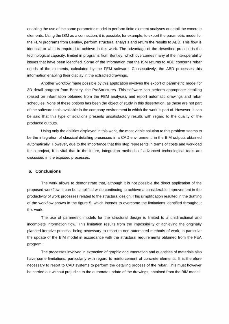
The work allows to demonstrate that, although it is not possible the direct application of the
proposed workflow, it can be simplified while continuing to achieve a considerable improvement in the
productivity of work processes related to the structural design. This simplification resulted in the drafting
of the workflow shown in the figure 5, which intends to overcome the limitations identified throughout
this work.
The use of parametric models for the structural design is limited to a unidirectional and
incomplete information flow. This limitation results from the impossibility of achieving the originally
planned iterative process, being necessary to resort to non-automated methods of work, in particular
the update of the BIM model in accordance with the structural requirements obtained from the FEA
program.
The processes involved in extraction of graphic documentation and quantities of materials also
have some limitations, particularly with regard to reinforcement of concrete elements. It is therefore
necessary to resort to CAD systems to perform the detailing process of the rebar. This must however
be carried out without prejudice to the automate update of the drawings, obtained from the BIM model.
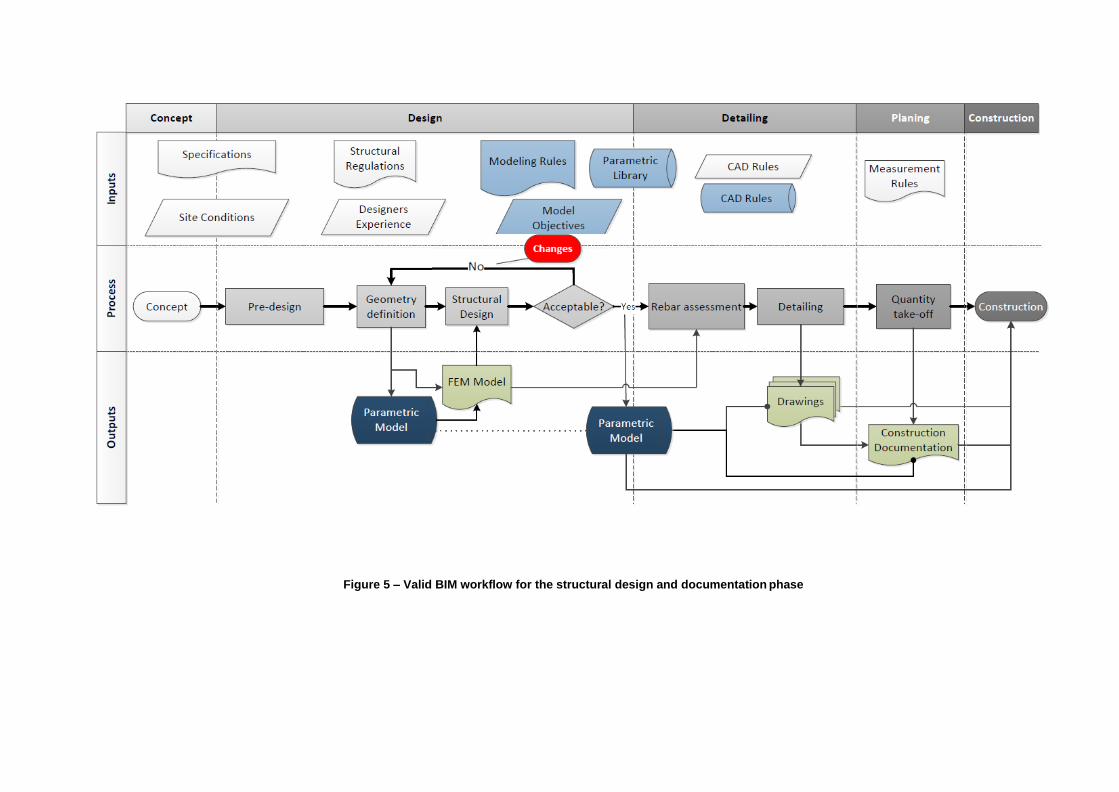
Figure 5 – Valid BIM workflow for the structural design and documentation phase
References
[1] - Davies, N. (2012) – Pratical Architectural modelling with AECOsim Building Designer,
Bentley Institute Press
[2] - Eastman, C. et al. (2011) – BIM Handbook, a guide to Building Information Modeling for
Owners, Managers, Desigers, Engineers, and Contractors, John Wiley & Sons Inc.
[3] - Jernigan, F. (2008) – Big BIM little BIM: the practical approach to building information
modeling: integrated practice done the right way, 4SitePress
[4] - Vasconcelos, T. (2010) – Building Information Model – Avaliação do seu potencial como
solução para os principais atrasos e desperdícios na construção portuguesa, Dissertação de Mestrado
Integrado em Engenharia Civil, Faculdade de Ciências e Tecnologia da Universidade Nova de Lisboa
[5] - Serra, P. (2015) – Análise da Implementação de Processos BIM Aplicados ao Projeto de
Estruturas, Dissertação de Mestrado Integrado em Engenharia Civil, Instituto Superior Técnico
[6] - Shoegnome: http://www.shoegnome.com/2013/02/05/primarybenefitsofbim/ consult. em
27-03-2015