Embed Size (px)
Citation preview
Instruction Manual
Reference SL Articulator and Face Bow Systems Reference AB, Condylograph Set, Condylograph comfort Set, and
Condylograph comfort Set I
Instruction Manual
- 2 -
Important notice:
For your own safety, as well as for operational safety, please read these instruc-tions thoroughly before beginning to operate the device. Always comply with any and all warnings included in these instructions, and/or on the device itself.
Manufacturer:
GAMMA Medizinisch-wissenschaftliche Fortbildungs-GmbH A-3400 Klosterneuburg, Josef Brenner-Straße 10
Reference SL Articulator and Face Bow Systems
- 3 -
Instruction Manual
Reference SL Articulator and Face Bow Systems Reference AB, Condylograph Set,
Condylograph comfort Set, and Condylograph comfort Set I
Curve of Spee Analyzer
CPV (Condylar Position Variator)
Revision 2018-06-28
© Copyright 2018 GAMMA Medizinisch-wissenschaftliche Fortbildungs-GmbH
Josef Brenner Straße 10 3400 Klosterneuburg
Österreich Phone: +43 2243 34140 Fax: +43 2243 34140 90
E-Mail: [email protected] Internet: www.gammadental.com
Instruction Manual
- 4 -
Content
1 Warnings and safety information ................................................................ 5
2 Intended purpose and mode of application ................................................. 6
3 Reference AB face bow .............................................................................. 7
4 Reference SL articulator ........................................................................... 11 4.1 Introduction .............................................................................................. 11 4.2 Mounting system ...................................................................................... 12 4.3 Transferring the upper jaw model ............................................................. 14 4.3.1 Transfer according to the anatomic axis (Reference AB face bow) ........... 14 4.3.2 Transfer according to the kinematic axis ................................................... 17 4.3.2.1 With Condylograph comfort Set and Condylograph comfort Set I ............. 17 4.3.2.2 With Condylograph Set ............................................................................. 24 4.4 Mounting the lower jaw models in the articulator ...................................... 32 4.5 Eccentric articulator programming ............................................................ 36
5 Calibration of the Reference SL articulator ............................................... 40
6 Curve of Spee Analyzer Set ..................................................................... 48
7 CPV (Condylar Position Variator) ............................................................. 54
8 Maintenance and cleaning ........................................................................ 58
Reference SL Articulator and Face Bow Systems
- 5 -
1 Warnings and safety information
The instruments are designed for use in the dental practice and lab. Initial start-up and operation must be according to the instructions manual.
Furthermore, it is the owner's responsibility to check up on the adequacy and ap-plicability of the devices for the intended purpose before initial start-up, unless it is listed in the instructions manual.
The manufacturer does not assume liability for damages caused by improper us-age, incorrect handling or improper repair.
All maintenance and servicing tasks, other than operations mentioned in the in-structions manual, should only be done by authorized specialists.
Use original GAMMA spare parts only!
Instruction Manual
- 6 -
2 Intended purpose and mode of application
The face bows of the Reference system serve two purposes. Firstly, they are required accesso-ries to the CADIAX system, because the flags and styli of the CADIAX are mounted onto the face bows. Secondly, the face bows are used for determining the relation of the patient’s jaw to a cranial reference plane. This assessment of jaw relation is necessary for mounting the jaw mod-els in the correct position within the articulator.
During the application of the face bow, the following circumstances can prevent or limit the usage of the face bow:
• General diseases: Patients with diseases that prevent the mounting of a face bow. The diseases can be physical or psychological in nature. (e.g. spasticity, epilepsy, claustrophobia, injuries or diseases regarding the bony skull or soft tissue structures of the skull, such as the ear, etc.)
• Special diseases in the aural area: Patients with diseases in the area of the ear. (e.g. painful inflammations, tinnitus, pain in the ear, etc.)
This instruction manual describes the application of the devices. The usage of articulators and face bows is part of the dental medical education. A briefing regarding the handling of the prod-ucts by our own personnel or by personnel of our retailers is not required.
Interference and/or operation of the devices by the patient is not intended. However, active co-operation of the patient is necessary for obtaining the desired examination results. For this rea-son, special attention has to be given to the patient’s cognitive abilities during the examination of children, elders or handicapped people. This group of patients has to be carefully prepared for the examination in particular.
The application of the face bows on the patient during the assessment of jaw relation is completed in a few minutes. Articulators are not used on the patient.
Reference SL Articulator and Face Bow Systems
- 7 -
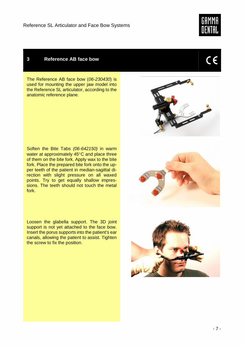
3 Reference AB face bow
The Reference AB face bow (06-230430) is used for mounting the upper jaw model into the Reference SL articulator, according to the anatomic reference plane.
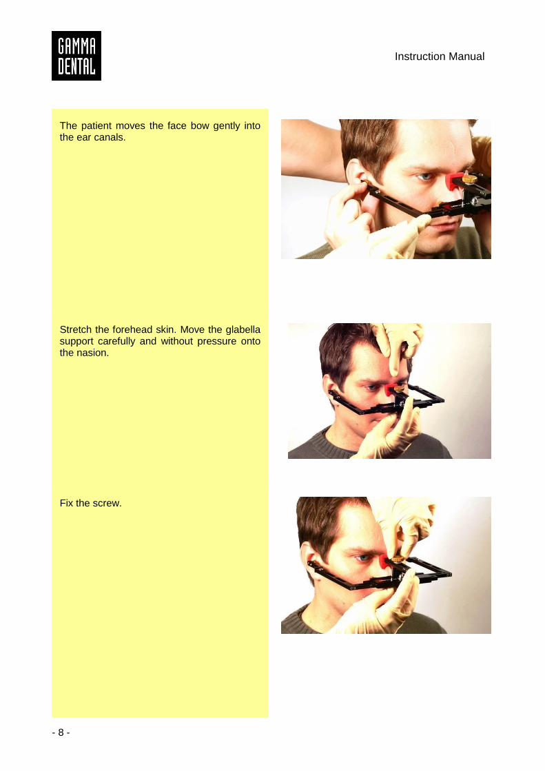
Soften the Bite Tabs (06-642150) in warm
water at approximately 45C and place three of them on the bite fork. Apply wax to the bite fork. Place the prepared bite fork onto the up-per teeth of the patient in median-sagittal di-rection with slight pressure on all waxed points. Try to get equally shallow impres-sions. The teeth should not touch the metal fork.
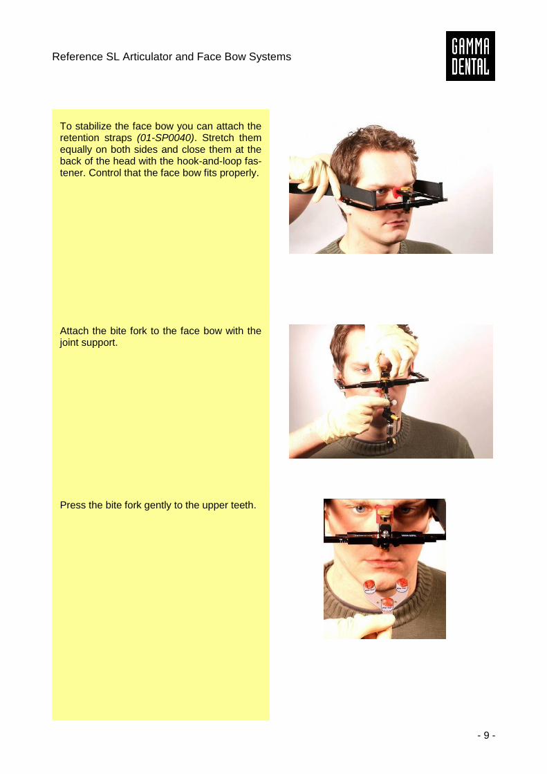
Loosen the glabella support. The 3D joint support is not yet attached to the face bow. Insert the porus supports into the patient's ear canals, allowing the patient to assist. Tighten the screw to fix the position.
Instruction Manual
- 8 -
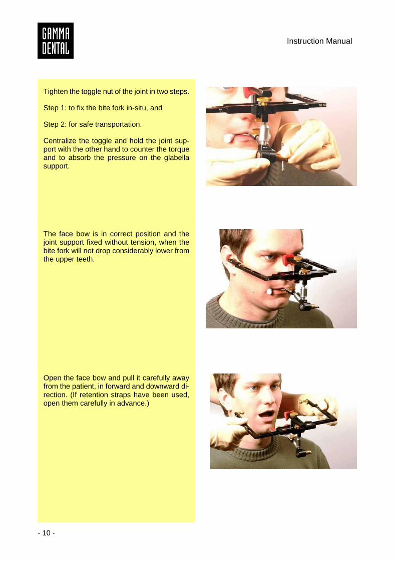
The patient moves the face bow gently into the ear canals.
Stretch the forehead skin. Move the glabella support carefully and without pressure onto the nasion.
Fix the screw.
Reference SL Articulator and Face Bow Systems
- 9 -
To stabilize the face bow you can attach the retention straps (01-SP0040). Stretch them equally on both sides and close them at the back of the head with the hook-and-loop fas-tener. Control that the face bow fits properly.
Attach the bite fork to the face bow with the joint support.
Press the bite fork gently to the upper teeth.
Instruction Manual
- 10 -
Tighten the toggle nut of the joint in two steps.
Step 1: to fix the bite fork in-situ, and
Step 2: for safe transportation.
Centralize the toggle and hold the joint sup-port with the other hand to counter the torque and to absorb the pressure on the glabella support.
The face bow is in correct position and the joint support fixed without tension, when the bite fork will not drop considerably lower from the upper teeth.
Open the face bow and pull it carefully away from the patient, in forward and downward di-rection. (If retention straps have been used, open them carefully in advance.)
Reference SL Articulator and Face Bow Systems
- 11 -
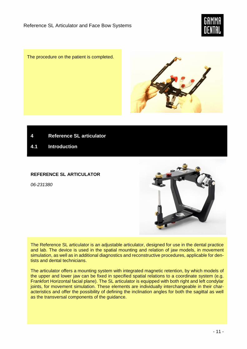
The procedure on the patient is completed.
4 Reference SL articulator
4.1 Introduction
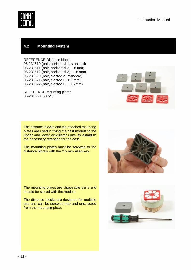
REFERENCE SL ARTICULATOR
06-231380
The Reference SL articulator is an adjustable articulator, designed for use in the dental practice and lab. The device is used in the spatial mounting and relation of jaw models, in movement simulation, as well as in additional diagnostics and reconstructive procedures, applicable for den-tists and dental technicians.
The articulator offers a mounting system with integrated magnetic retention, by which models of the upper and lower jaw can be fixed in specified spatial relations to a coordinate system (e.g. Frankfort Horizontal facial plane). The SL articulator is equipped with both right and left condylar joints, for movement simulation. These elements are individually interchangeable in their char-acteristics and offer the possibility of defining the inclination angles for both the sagittal as well as the transversal components of the guidance.
Instruction Manual
- 12 -
4.2 Mounting system
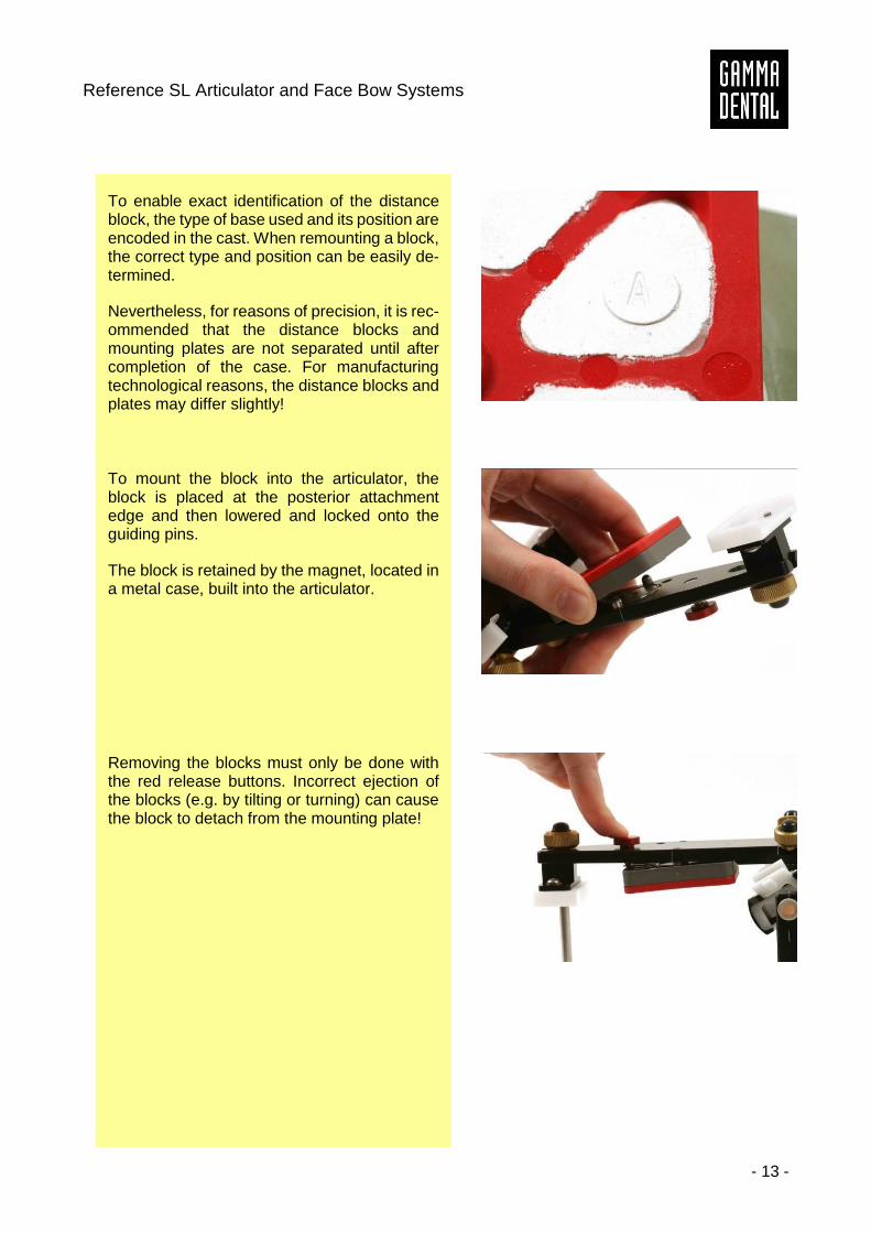
REFERENCE Distance blocks 06-231510-(pair, horizontal 1, standard) 06-231511-(pair, horizontal 2, + 8 mm) 06-231512-(pair, horizontal 3, + 16 mm) 06-231520-(pair, slanted A, standard) 06-231521-(pair, slanted B, + 8 mm) 06-231522-(pair, slanted C, + 16 mm)
REFERENCE Mounting plates 06-231550 (50 pc.)
The distance blocks and the attached mounting plates are used in fixing the cast models to the upper and lower articulator units, to establish the necessary retention for the cast.
The mounting plates must be screwed to the distance blocks with the 2.5 mm Allen key.
The mounting plates are disposable parts and should be stored with the models.
The distance blocks are designed for multiple use and can be screwed into and unscrewed from the mounting plate.
Reference SL Articulator and Face Bow Systems
- 13 -
To enable exact identification of the distance block, the type of base used and its position are encoded in the cast. When remounting a block, the correct type and position can be easily de-termined.
Nevertheless, for reasons of precision, it is rec-ommended that the distance blocks and mounting plates are not separated until after completion of the case. For manufacturing technological reasons, the distance blocks and plates may differ slightly!
To mount the block into the articulator, the block is placed at the posterior attachment edge and then lowered and locked onto the guiding pins.
The block is retained by the magnet, located in a metal case, built into the articulator.
Removing the blocks must only be done with the red release buttons. Incorrect ejection of the blocks (e.g. by tilting or turning) can cause the block to detach from the mounting plate!
Instruction Manual
- 14 -
4.3 Transferring the upper jaw model
4.3.1 Transfer according to the anatomic axis (Reference AB face bow)
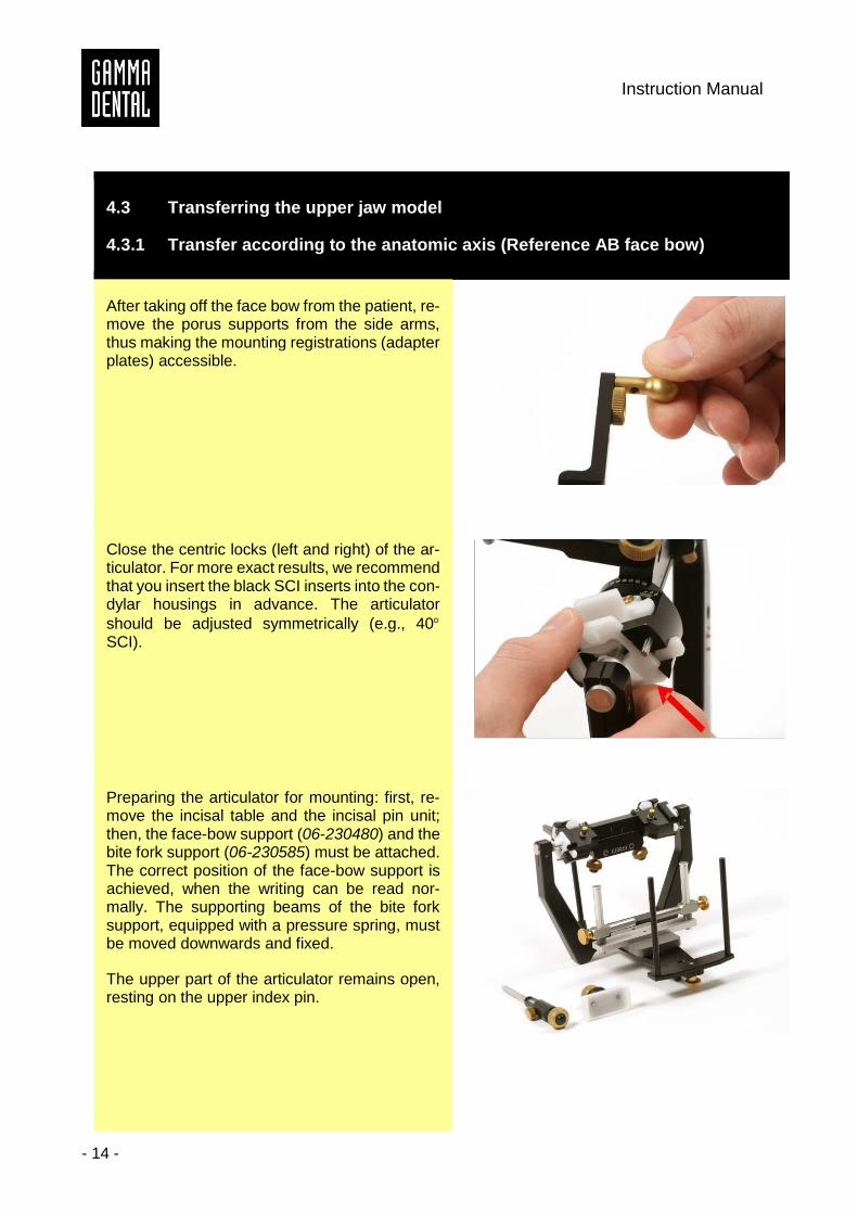
After taking off the face bow from the patient, re-move the porus supports from the side arms, thus making the mounting registrations (adapter plates) accessible.
Close the centric locks (left and right) of the ar-ticulator. For more exact results, we recommend that you insert the black SCI inserts into the con-dylar housings in advance. The articulator
should be adjusted symmetrically (e.g., 40 SCI).
Preparing the articulator for mounting: first, re-move the incisal table and the incisal pin unit; then, the face-bow support (06-230480) and the bite fork support (06-230585) must be attached. The correct position of the face-bow support is achieved, when the writing can be read nor-mally. The supporting beams of the bite fork support, equipped with a pressure spring, must be moved downwards and fixed.
The upper part of the articulator remains open, resting on the upper index pin.
Reference SL Articulator and Face Bow Systems
- 15 -
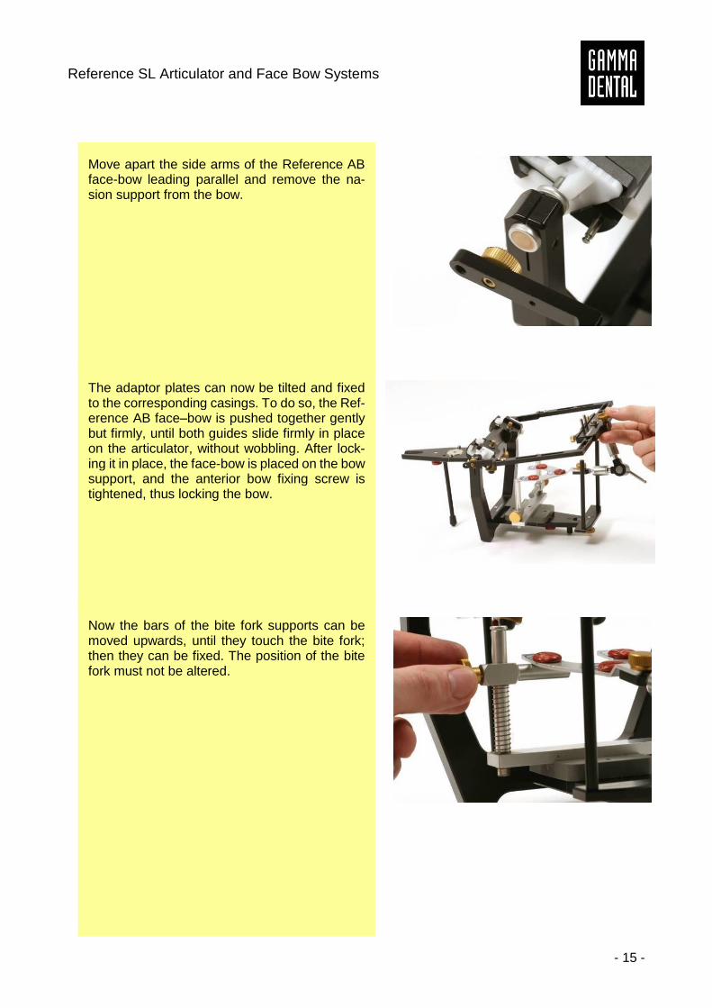
Move apart the side arms of the Reference AB face-bow leading parallel and remove the na-sion support from the bow.
The adaptor plates can now be tilted and fixed to the corresponding casings. To do so, the Ref-erence AB face–bow is pushed together gently but firmly, until both guides slide firmly in place on the articulator, without wobbling. After lock-ing it in place, the face-bow is placed on the bow support, and the anterior bow fixing screw is tightened, thus locking the bow.
Now the bars of the bite fork supports can be moved upwards, until they touch the bite fork; then they can be fixed. The position of the bite fork must not be altered.
Instruction Manual
- 16 -
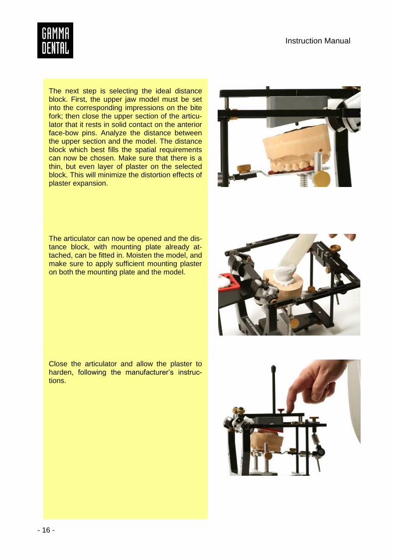
The next step is selecting the ideal distance block. First, the upper jaw model must be set into the corresponding impressions on the bite fork; then close the upper section of the articu-lator that it rests in solid contact on the anterior face-bow pins. Analyze the distance between the upper section and the model. The distance block which best fills the spatial requirements can now be chosen. Make sure that there is a thin, but even layer of plaster on the selected block. This will minimize the distortion effects of plaster expansion.
The articulator can now be opened and the dis-tance block, with mounting plate already at-tached, can be fitted in. Moisten the model, and make sure to apply sufficient mounting plaster on both the mounting plate and the model.
Close the articulator and allow the plaster to harden, following the manufacturer’s instruc-tions.
Reference SL Articulator and Face Bow Systems
- 17 -
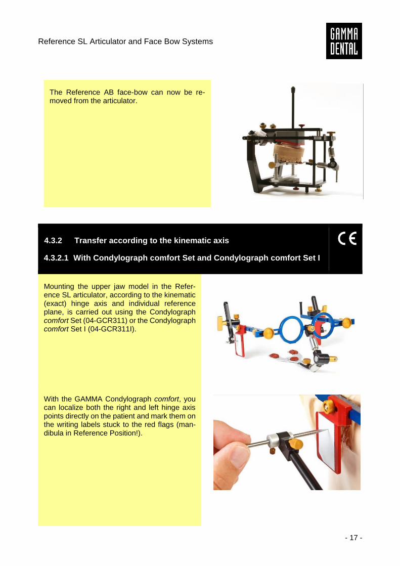
The Reference AB face-bow can now be re-moved from the articulator.
4.3.2 Transfer according to the kinematic axis
4.3.2.1 With Condylograph comfort Set and Condylograph comfort Set I
Mounting the upper jaw model in the Refer-ence SL articulator, according to the kinematic (exact) hinge axis and individual reference plane, is carried out using the Condylograph comfort Set (04-GCR311) or the Condylograph comfort Set I (04-GCR311I).
With the GAMMA Condylograph comfort, you can localize both the right and left hinge axis points directly on the patient and mark them on the writing labels stuck to the red flags (man-dibula in Reference Position!).
Instruction Manual
- 18 -
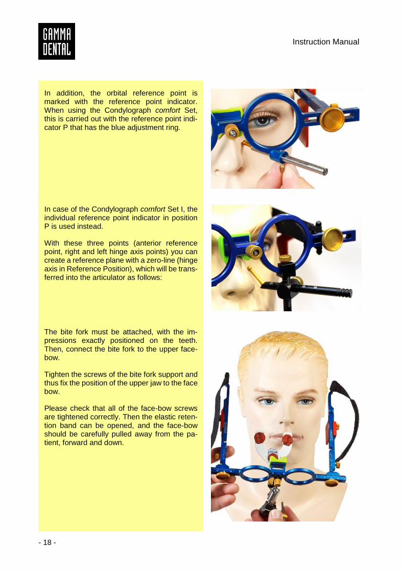
In addition, the orbital reference point is marked with the reference point indicator. When using the Condylograph comfort Set, this is carried out with the reference point indi-cator P that has the blue adjustment ring.
In case of the Condylograph comfort Set I, the individual reference point indicator in position P is used instead.
With these three points (anterior reference point, right and left hinge axis points) you can create a reference plane with a zero-line (hinge axis in Reference Position), which will be trans-ferred into the articulator as follows:
The bite fork must be attached, with the im-pressions exactly positioned on the teeth. Then, connect the bite fork to the upper face-bow.
Tighten the screws of the bite fork support and thus fix the position of the upper jaw to the face bow.
Please check that all of the face-bow screws are tightened correctly. Then the elastic reten-tion band can be opened, and the face-bow should be carefully pulled away from the pa-tient, forward and down.
Reference SL Articulator and Face Bow Systems
- 19 -
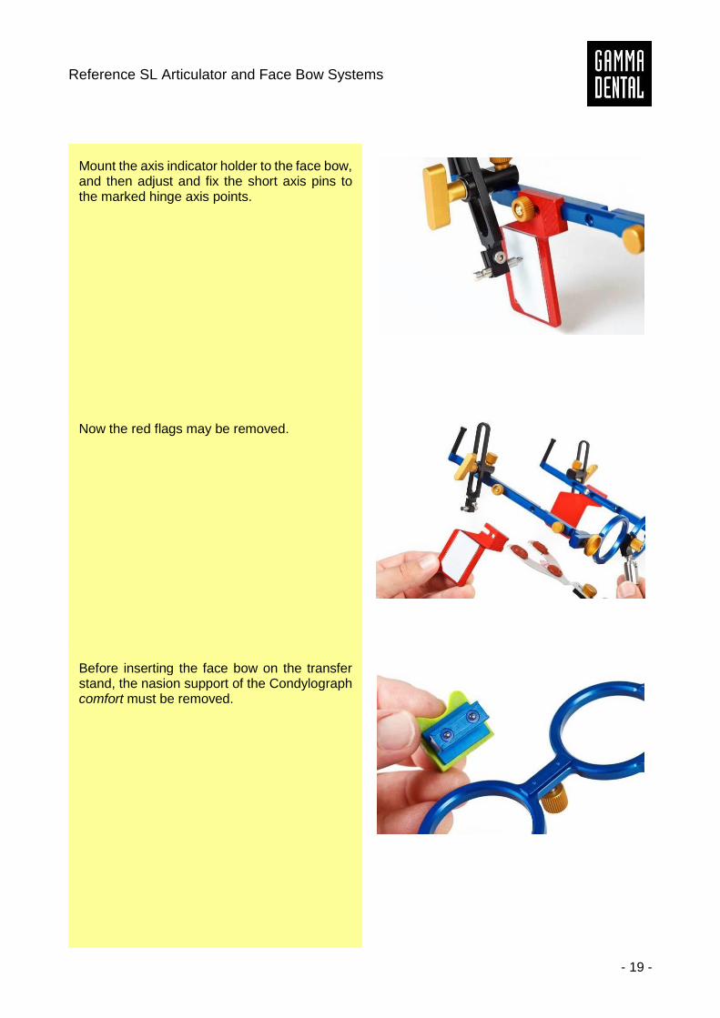
Mount the axis indicator holder to the face bow, and then adjust and fix the short axis pins to the marked hinge axis points.
Now the red flags may be removed.
Before inserting the face bow on the transfer stand, the nasion support of the Condylograph comfort must be removed.
Instruction Manual
- 20 -
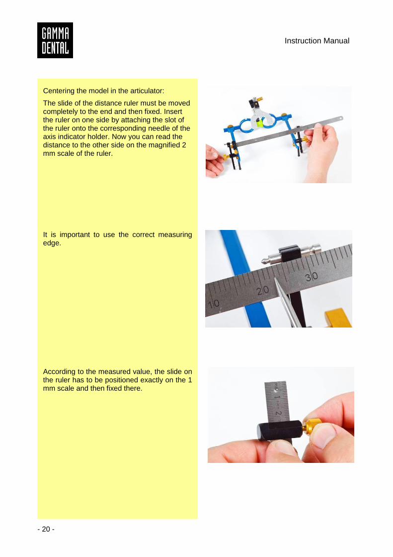
Centering the model in the articulator:
The slide of the distance ruler must be moved completely to the end and then fixed. Insert the ruler on one side by attaching the slot of the ruler onto the corresponding needle of the axis indicator holder. Now you can read the distance to the other side on the magnified 2 mm scale of the ruler.
It is important to use the correct measuring edge.
According to the measured value, the slide on the ruler has to be positioned exactly on the 1 mm scale and then fixed there.
Reference SL Articulator and Face Bow Systems
- 21 -
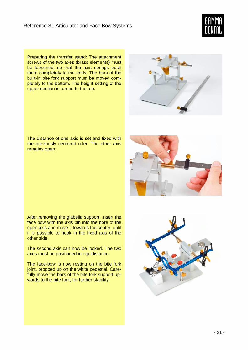
Preparing the transfer stand: The attachment screws of the two axes (brass elements) must be loosened, so that the axis springs push them completely to the ends. The bars of the built-in bite fork support must be moved com-pletely to the bottom. The height setting of the upper section is turned to the top.
The distance of one axis is set and fixed with the previously centered ruler. The other axis remains open.
After removing the glabella support, insert the face bow with the axis pin into the bore of the open axis and move it towards the center, until it is possible to hook in the fixed axis of the other side.
The second axis can now be locked. The two axes must be positioned in equidistance.
The face-bow is now resting on the bite fork joint, propped up on the white pedestal. Care-fully move the bars of the bite fork support up-wards to the bite fork, for further stability.
Instruction Manual
- 22 -
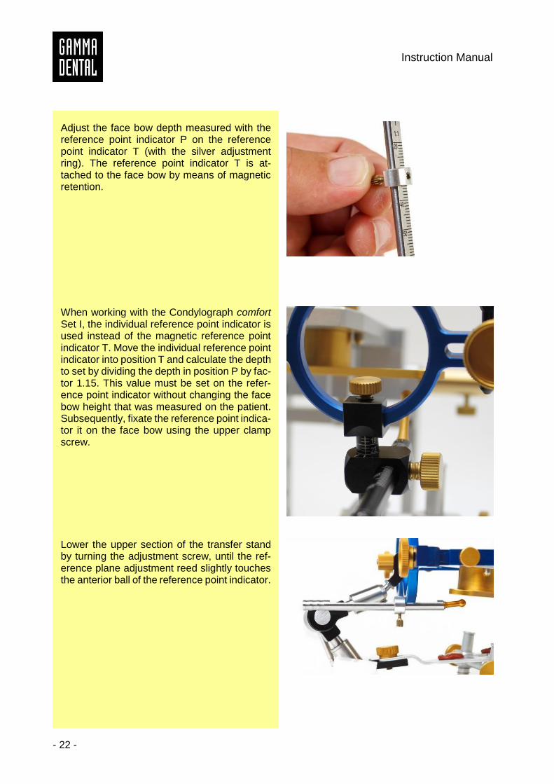
Adjust the face bow depth measured with the reference point indicator P on the reference point indicator T (with the silver adjustment ring). The reference point indicator T is at-tached to the face bow by means of magnetic retention.
When working with the Condylograph comfort Set I, the individual reference point indicator is used instead of the magnetic reference point indicator T. Move the individual reference point indicator into position T and calculate the depth to set by dividing the depth in position P by fac-tor 1.15. This value must be set on the refer-ence point indicator without changing the face bow height that was measured on the patient. Subsequently, fixate the reference point indica-tor it on the face bow using the upper clamp screw.
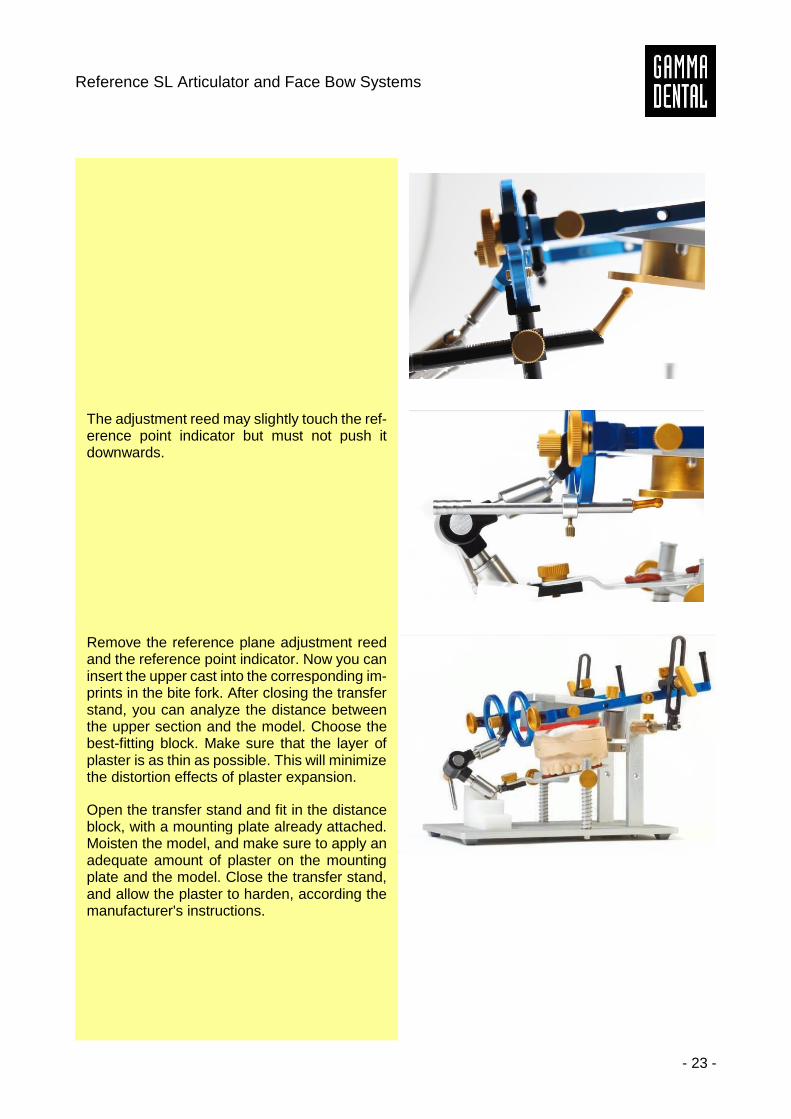
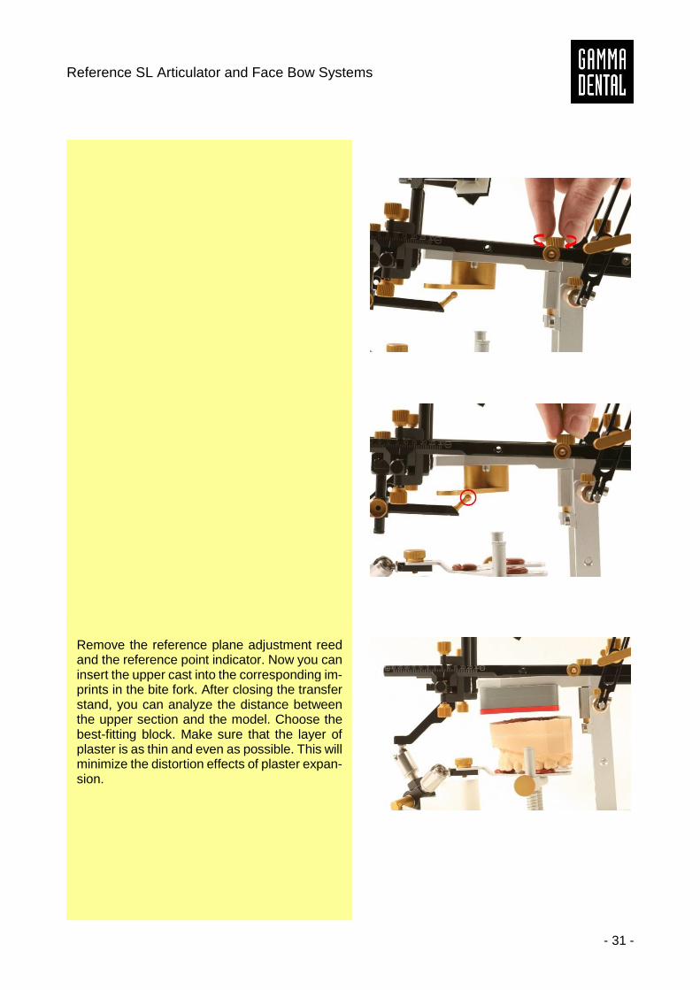
Lower the upper section of the transfer stand by turning the adjustment screw, until the ref-erence plane adjustment reed slightly touches the anterior ball of the reference point indicator.
Reference SL Articulator and Face Bow Systems
- 23 -
The adjustment reed may slightly touch the ref-erence point indicator but must not push it downwards.
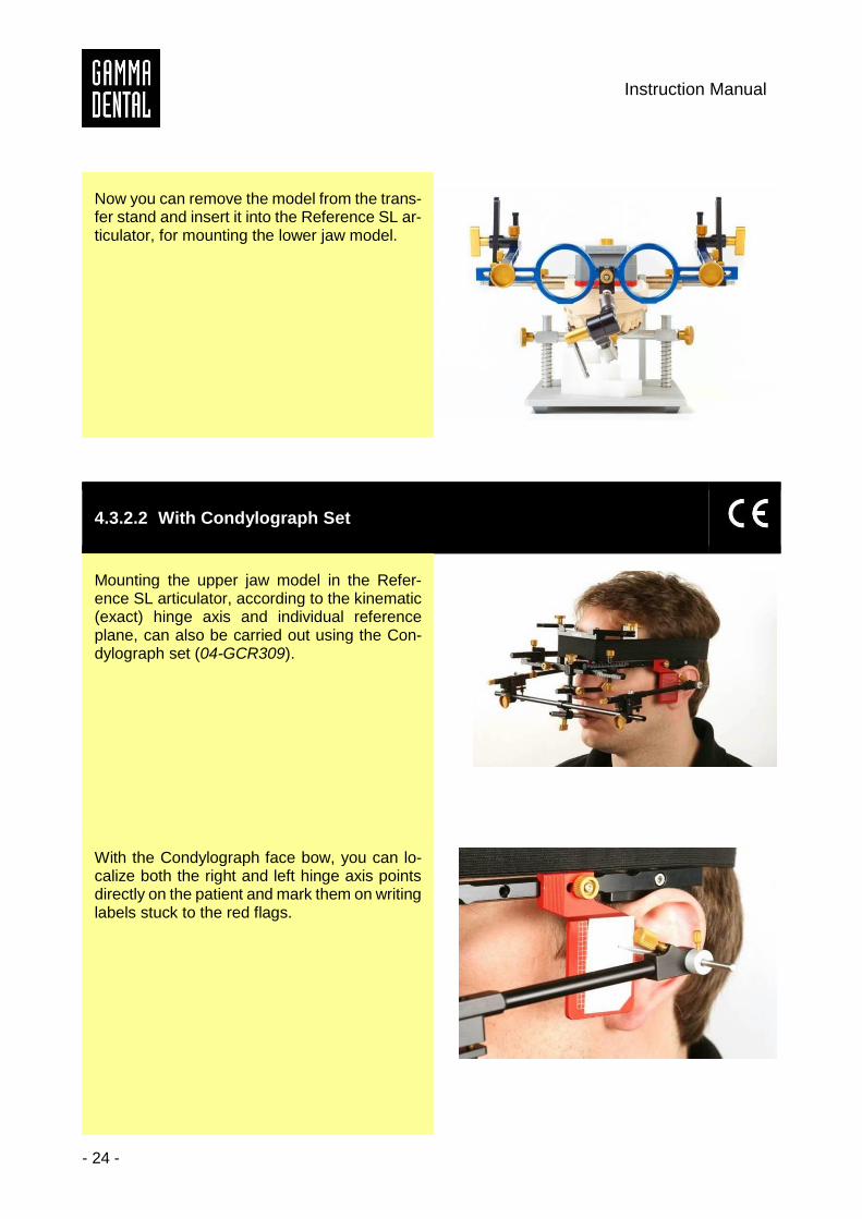
Remove the reference plane adjustment reed and the reference point indicator. Now you can insert the upper cast into the corresponding im-prints in the bite fork. After closing the transfer stand, you can analyze the distance between the upper section and the model. Choose the best-fitting block. Make sure that the layer of plaster is as thin as possible. This will minimize the distortion effects of plaster expansion.
Open the transfer stand and fit in the distance block, with a mounting plate already attached. Moisten the model, and make sure to apply an adequate amount of plaster on the mounting plate and the model. Close the transfer stand, and allow the plaster to harden, according the manufacturer's instructions.
Instruction Manual
- 24 -
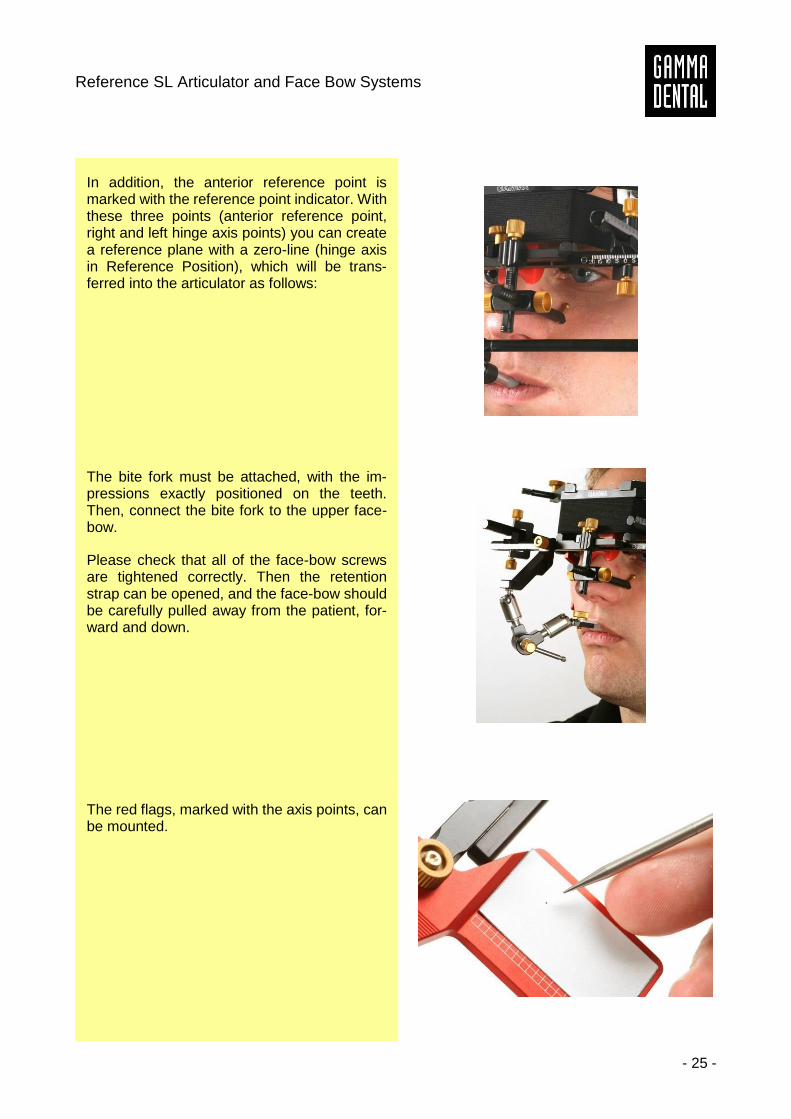
Now you can remove the model from the trans-fer stand and insert it into the Reference SL ar-ticulator, for mounting the lower jaw model.
4.3.2.2 With Condylograph Set
Mounting the upper jaw model in the Refer-ence SL articulator, according to the kinematic (exact) hinge axis and individual reference plane, can also be carried out using the Con-dylograph set (04-GCR309).
With the Condylograph face bow, you can lo-calize both the right and left hinge axis points directly on the patient and mark them on writing labels stuck to the red flags.
Reference SL Articulator and Face Bow Systems
- 25 -
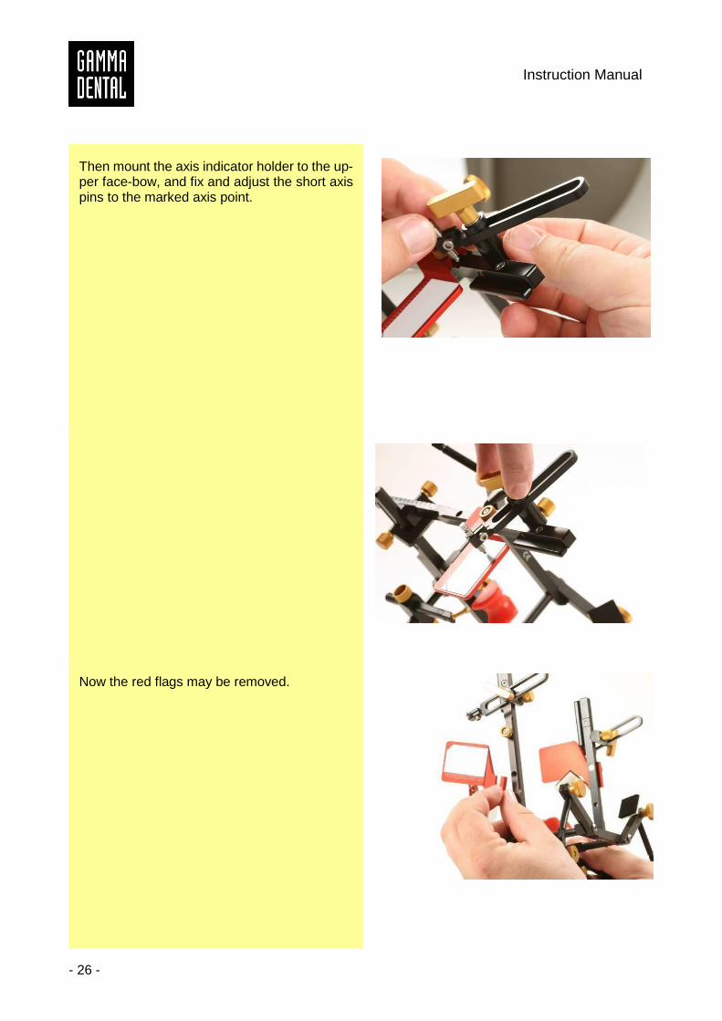
In addition, the anterior reference point is marked with the reference point indicator. With these three points (anterior reference point, right and left hinge axis points) you can create a reference plane with a zero-line (hinge axis in Reference Position), which will be trans-ferred into the articulator as follows:
The bite fork must be attached, with the im-pressions exactly positioned on the teeth. Then, connect the bite fork to the upper face-bow.
Please check that all of the face-bow screws are tightened correctly. Then the retention strap can be opened, and the face-bow should be carefully pulled away from the patient, for-ward and down.
The red flags, marked with the axis points, can be mounted.
Instruction Manual
- 26 -
Then mount the axis indicator holder to the up-per face-bow, and fix and adjust the short axis pins to the marked axis point.
Now the red flags may be removed.
Reference SL Articulator and Face Bow Systems
- 27 -
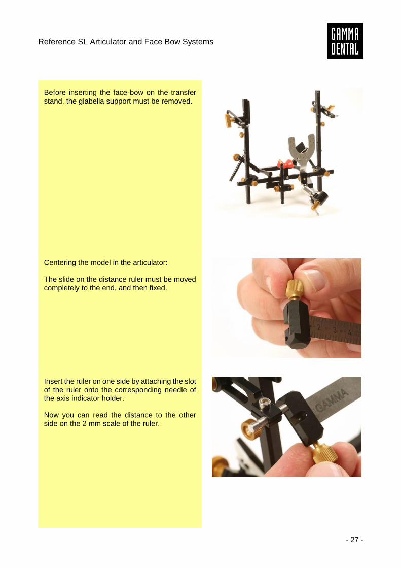
Before inserting the face-bow on the transfer stand, the glabella support must be removed.
Centering the model in the articulator:
The slide on the distance ruler must be moved completely to the end, and then fixed.
Insert the ruler on one side by attaching the slot of the ruler onto the corresponding needle of the axis indicator holder.
Now you can read the distance to the other side on the 2 mm scale of the ruler.
Instruction Manual
- 28 -
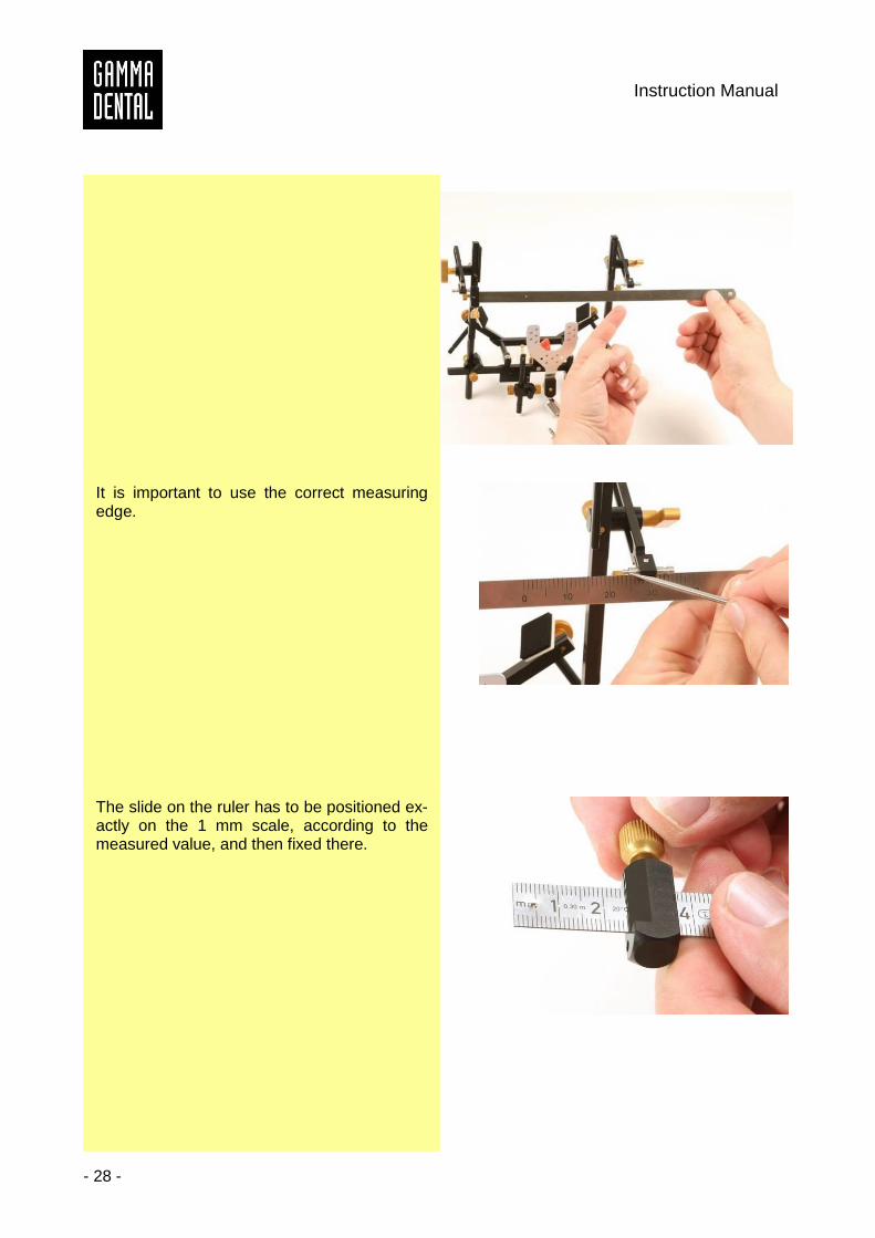
It is important to use the correct measuring edge.
The slide on the ruler has to be positioned ex-actly on the 1 mm scale, according to the measured value, and then fixed there.
Reference SL Articulator and Face Bow Systems
- 29 -
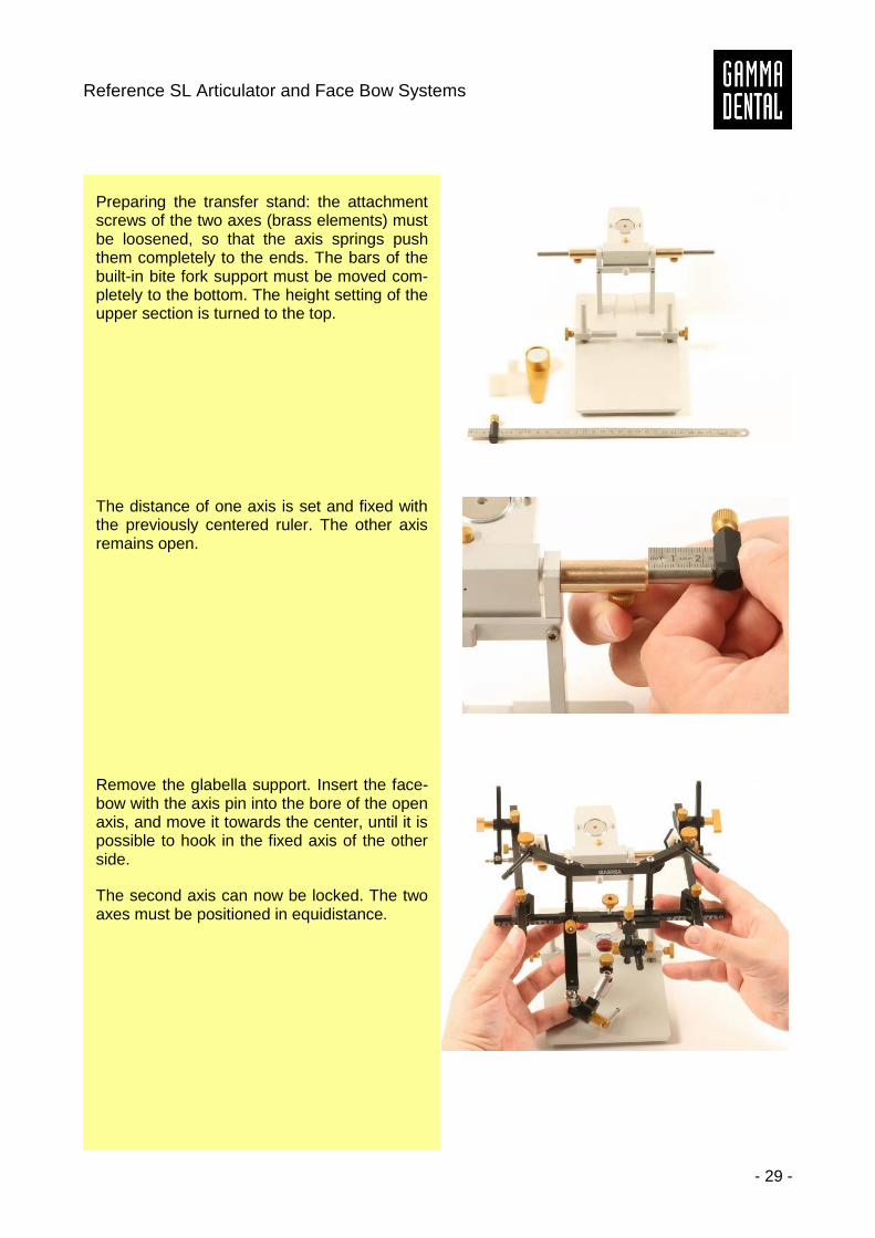
Preparing the transfer stand: the attachment screws of the two axes (brass elements) must be loosened, so that the axis springs push them completely to the ends. The bars of the built-in bite fork support must be moved com-pletely to the bottom. The height setting of the upper section is turned to the top.
The distance of one axis is set and fixed with the previously centered ruler. The other axis remains open.
Remove the glabella support. Insert the face-bow with the axis pin into the bore of the open axis, and move it towards the center, until it is possible to hook in the fixed axis of the other side.
The second axis can now be locked. The two axes must be positioned in equidistance.
Instruction Manual
- 30 -
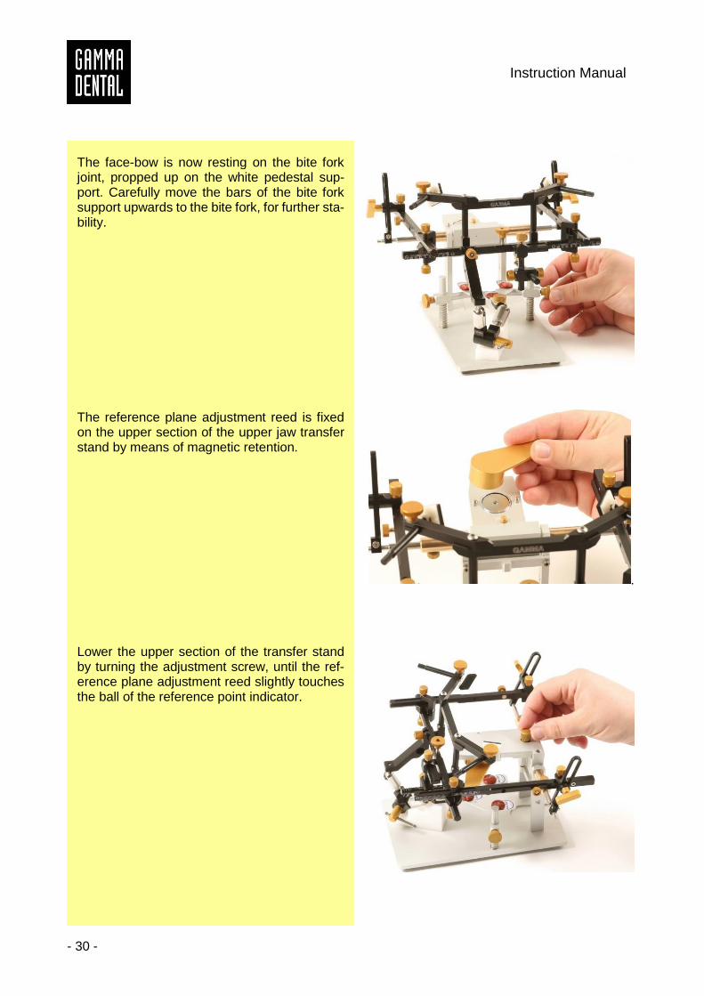
The face-bow is now resting on the bite fork joint, propped up on the white pedestal sup-port. Carefully move the bars of the bite fork support upwards to the bite fork, for further sta-bility.
The reference plane adjustment reed is fixed on the upper section of the upper jaw transfer stand by means of magnetic retention.
.
Lower the upper section of the transfer stand by turning the adjustment screw, until the ref-erence plane adjustment reed slightly touches the ball of the reference point indicator.
Reference SL Articulator and Face Bow Systems
- 31 -
Remove the reference plane adjustment reed and the reference point indicator. Now you can insert the upper cast into the corresponding im-prints in the bite fork. After closing the transfer stand, you can analyze the distance between the upper section and the model. Choose the best-fitting block. Make sure that the layer of plaster is as thin and even as possible. This will minimize the distortion effects of plaster expan-sion.
Instruction Manual
- 32 -
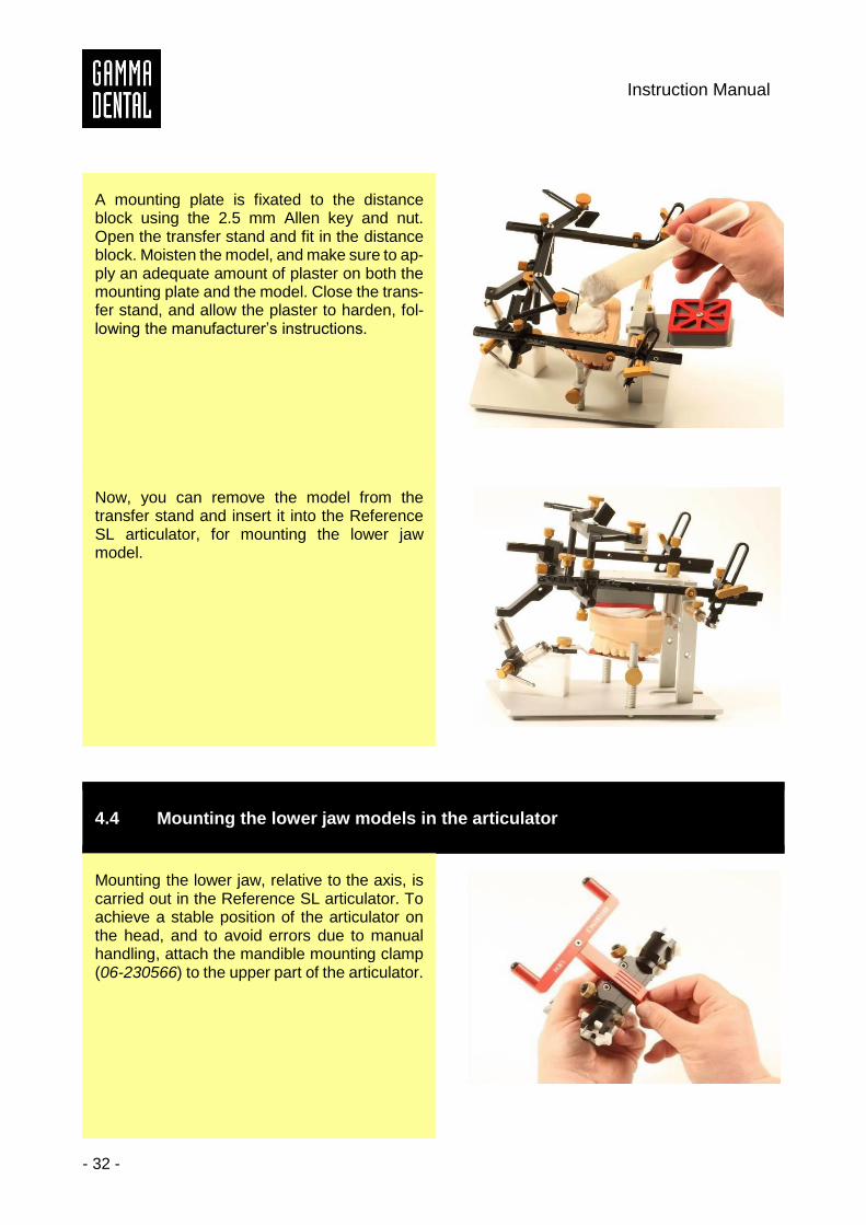
A mounting plate is fixated to the distance block using the 2.5 mm Allen key and nut. Open the transfer stand and fit in the distance block. Moisten the model, and make sure to ap-ply an adequate amount of plaster on both the mounting plate and the model. Close the trans-fer stand, and allow the plaster to harden, fol-lowing the manufacturer’s instructions.
Now, you can remove the model from the transfer stand and insert it into the Reference SL articulator, for mounting the lower jaw model.
4.4 Mounting the lower jaw models in the articulator
Mounting the lower jaw, relative to the axis, is carried out in the Reference SL articulator. To achieve a stable position of the articulator on the head, and to avoid errors due to manual handling, attach the mandible mounting clamp (06-230566) to the upper part of the articulator.
Reference SL Articulator and Face Bow Systems
- 33 -
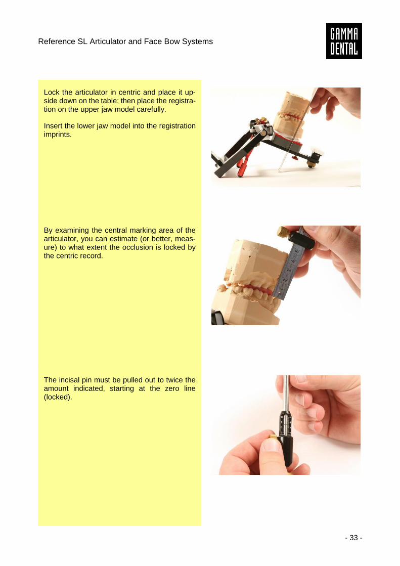
Lock the articulator in centric and place it up-side down on the table; then place the registra-tion on the upper jaw model carefully.
Insert the lower jaw model into the registration imprints.
By examining the central marking area of the articulator, you can estimate (or better, meas-ure) to what extent the occlusion is locked by the centric record.
The incisal pin must be pulled out to twice the amount indicated, starting at the zero line (locked).
Instruction Manual
- 34 -
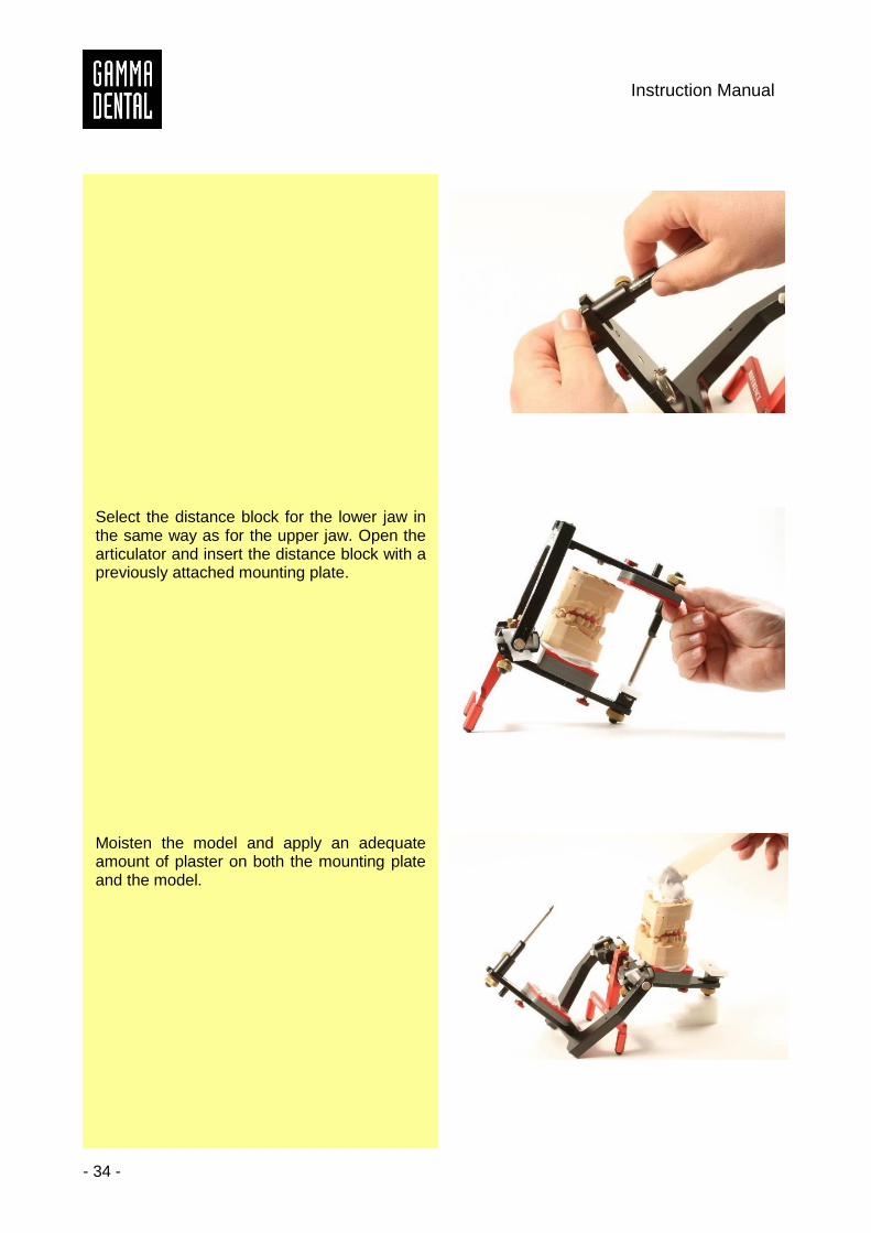
Select the distance block for the lower jaw in the same way as for the upper jaw. Open the articulator and insert the distance block with a previously attached mounting plate.
Moisten the model and apply an adequate amount of plaster on both the mounting plate and the model.
Reference SL Articulator and Face Bow Systems
- 35 -
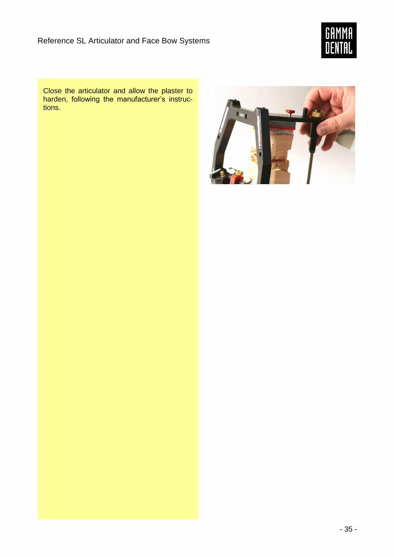
Close the articulator and allow the plaster to harden, following the manufacturer’s instruc-tions.
Instruction Manual
- 36 -
4.5 Eccentric articulator programming
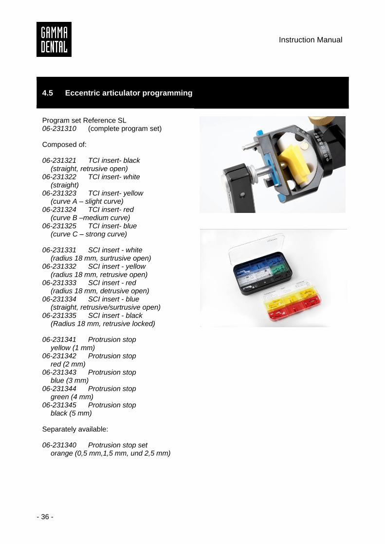
Program set Reference SL 06-231310 (complete program set)
Composed of:
06-231321 TCI insert- black (straight, retrusive open) 06-231322 TCI insert- white (straight) 06-231323 TCI insert- yellow (curve A – slight curve) 06-231324 TCI insert- red (curve B –medium curve) 06-231325 TCI insert- blue (curve C – strong curve)
06-231331 SCI insert - white (radius 18 mm, surtrusive open) 06-231332 SCI insert - yellow (radius 18 mm, retrusive open) 06-231333 SCI insert - red (radius 18 mm, detrusive open) 06-231334 SCI insert - blue (straight, retrusive/surtrusive open) 06-231335 SCI insert - black (Radius 18 mm, retrusive locked)
06-231341 Protrusion stop yellow (1 mm) 06-231342 Protrusion stop red (2 mm) 06-231343 Protrusion stop blue (3 mm) 06-231344 Protrusion stop green (4 mm) 06-231345 Protrusion stop black (5 mm)
Separately available:
06-231340 Protrusion stop set orange (0,5 mm,1,5 mm, und 2,5 mm)
Reference SL Articulator and Face Bow Systems
- 37 -
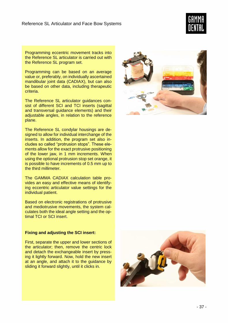
Programming eccentric movement tracks into the Reference SL articulator is carried out with the Reference SL program set.
Programming can be based on an average value or, preferably, on individually ascertained mandibular joint data (CADIAX), but can also be based on other data, including therapeutic criteria.
The Reference SL articulator guidances con-sist of different SCI and TCI inserts (sagittal and transversal guidance elements) and their adjustable angles, in relation to the reference plane.
The Reference SL condylar housings are de-signed to allow for individual interchange of the inserts. In addition, the program set also in-cludes so called “protrusion stops”. These ele-ments allow for the exact protrusive positioning of the lower jaw, in 1 mm increments. When using the optional protrusion stop set orange, it is possible to have increments of 0.5 mm up to the third millimeter.
The GAMMA CADIAX calculation table pro-vides an easy and effective means of identify-ing eccentric articulator value settings for the individual patient.
Based on electronic registrations of protrusive and mediotrusive movements, the system cal-culates both the ideal angle setting and the op-timal TCI or SCI insert.
Fixing and adjusting the SCI insert:
First, separate the upper and lower sections of the articulator; then, remove the centric lock and detach the exchangeable insert by press-ing it lightly forward. Now, hold the new insert at an angle, and attach it to the guidance by sliding it forward slightly, until it clicks in.

Instruction Manual
- 38 -
To adjust the angle, first loosen the condylar housing fixing screw. Set the desired value on the scale, then tighten the screw again.
Fixing and adjusting the TCI insert:
Simply pull out the old insert from the groove and slide in the new insert.
To set the angle, loosen the TCI attaching screw on the condylar housing back panel. Set the value on the scale, then tighten the screw again.
Reference SL Articulator and Face Bow Systems
- 39 -
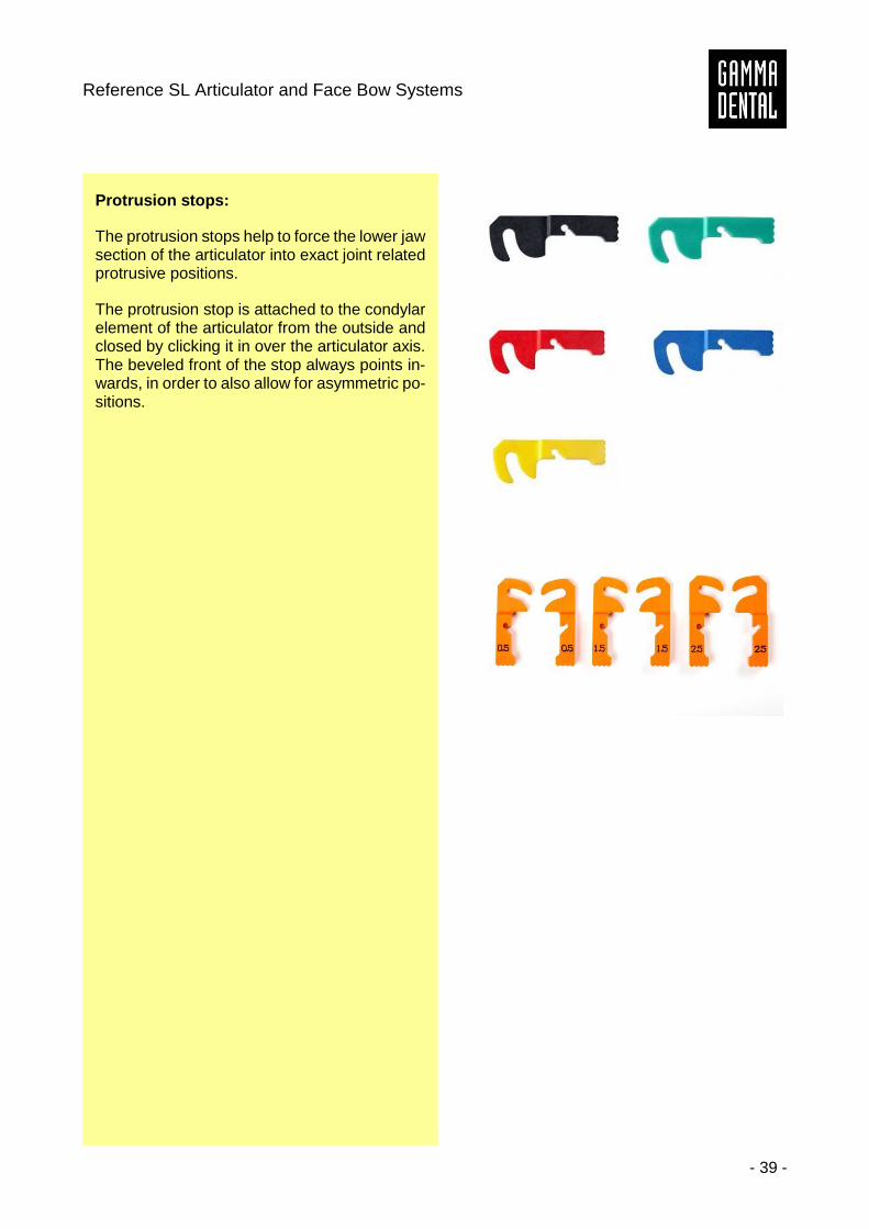
Protrusion stops:
The protrusion stops help to force the lower jaw section of the articulator into exact joint related protrusive positions.
The protrusion stop is attached to the condylar element of the articulator from the outside and closed by clicking it in over the articulator axis. The beveled front of the stop always points in-wards, in order to also allow for asymmetric po-sitions.
Instruction Manual
- 40 -
5 Calibration of the Reference SL articulator
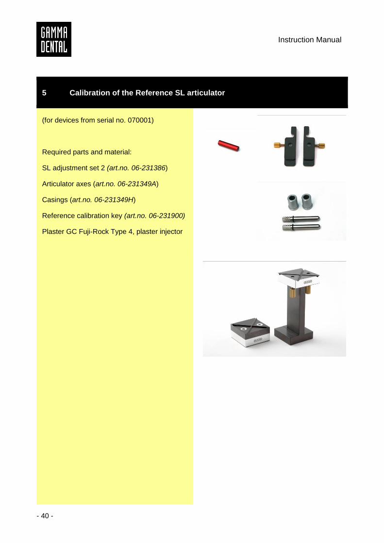
(for devices from serial no. 070001)
Required parts and material:
SL adjustment set 2 (art.no. 06-231386)
Articulator axes (art.no. 06-231349A)
Casings (art.no. 06-231349H)
Reference calibration key (art.no. 06-231900)
Plaster GC Fuji-Rock Type 4, plaster injector
Reference SL Articulator and Face Bow Systems
- 41 -
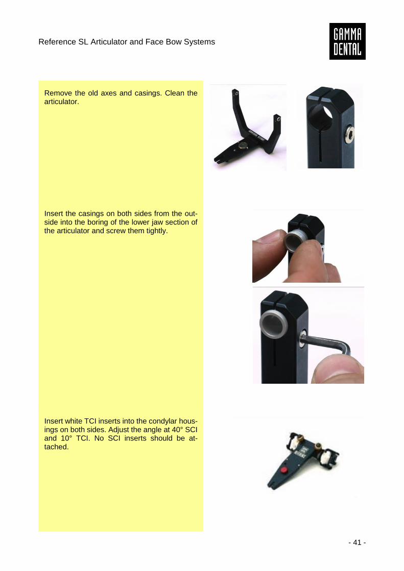
Remove the old axes and casings. Clean the articulator.
Insert the casings on both sides from the out-side into the boring of the lower jaw section of the articulator and screw them tightly.
Insert white TCI inserts into the condylar hous-ings on both sides. Adjust the angle at 40° SCI and 10° TCI. No SCI inserts should be at-tached.
Instruction Manual
- 42 -
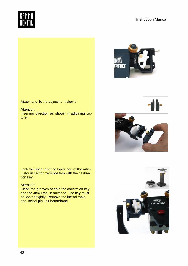
Attach and fix the adjustment blocks.
Attention: Inserting direction as shown in adjoining pic-ture!
Lock the upper and the lower part of the artic-ulator in centric zero position with the calibra-tion key.
Attention: Clean the grooves of both the calibration key and the articulator in advance. The key must be locked tightly! Remove the incisal table and incisal pin unit beforehand.
Reference SL Articulator and Face Bow Systems
- 43 -
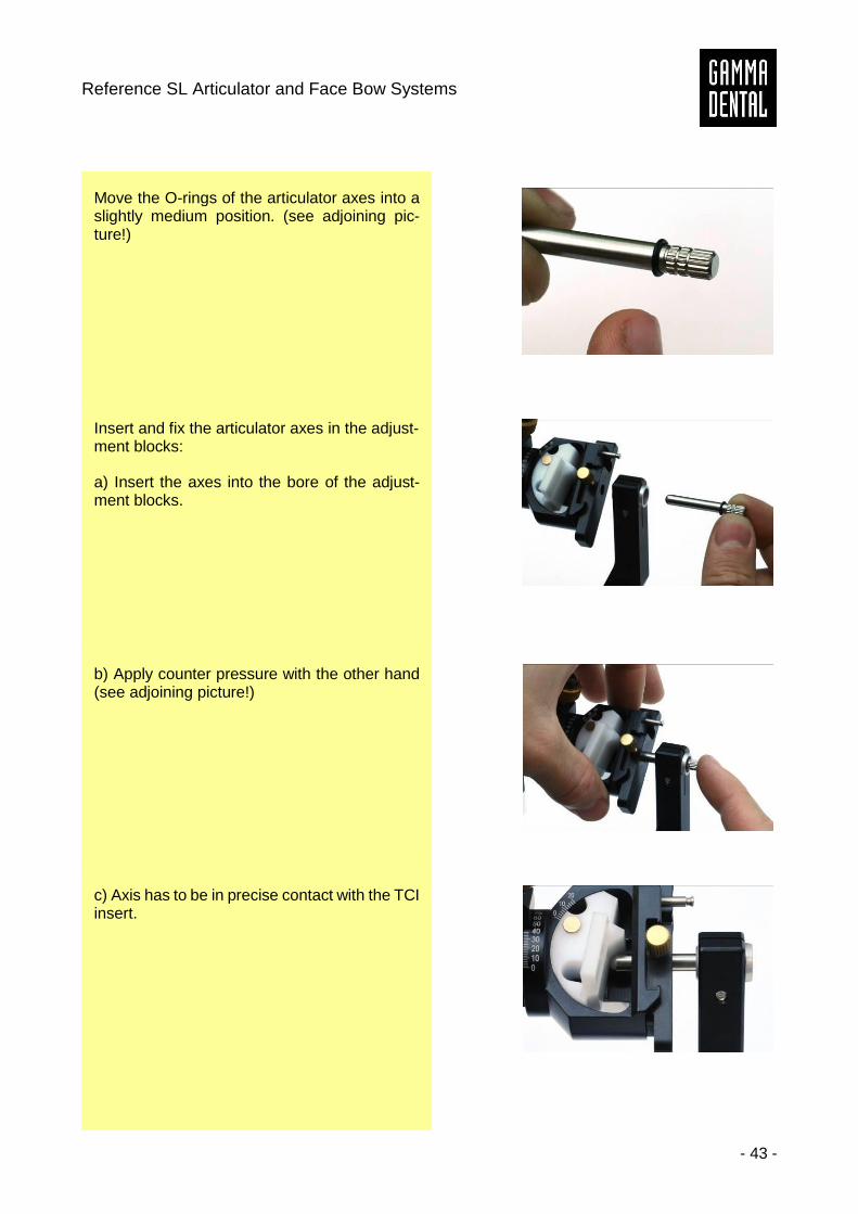
Move the O-rings of the articulator axes into a slightly medium position. (see adjoining pic-ture!)
Insert and fix the articulator axes in the adjust-ment blocks:
a) Insert the axes into the bore of the adjust-ment blocks.
b) Apply counter pressure with the other hand (see adjoining picture!)
c) Axis has to be in precise contact with the TCI insert.
Instruction Manual
- 44 -
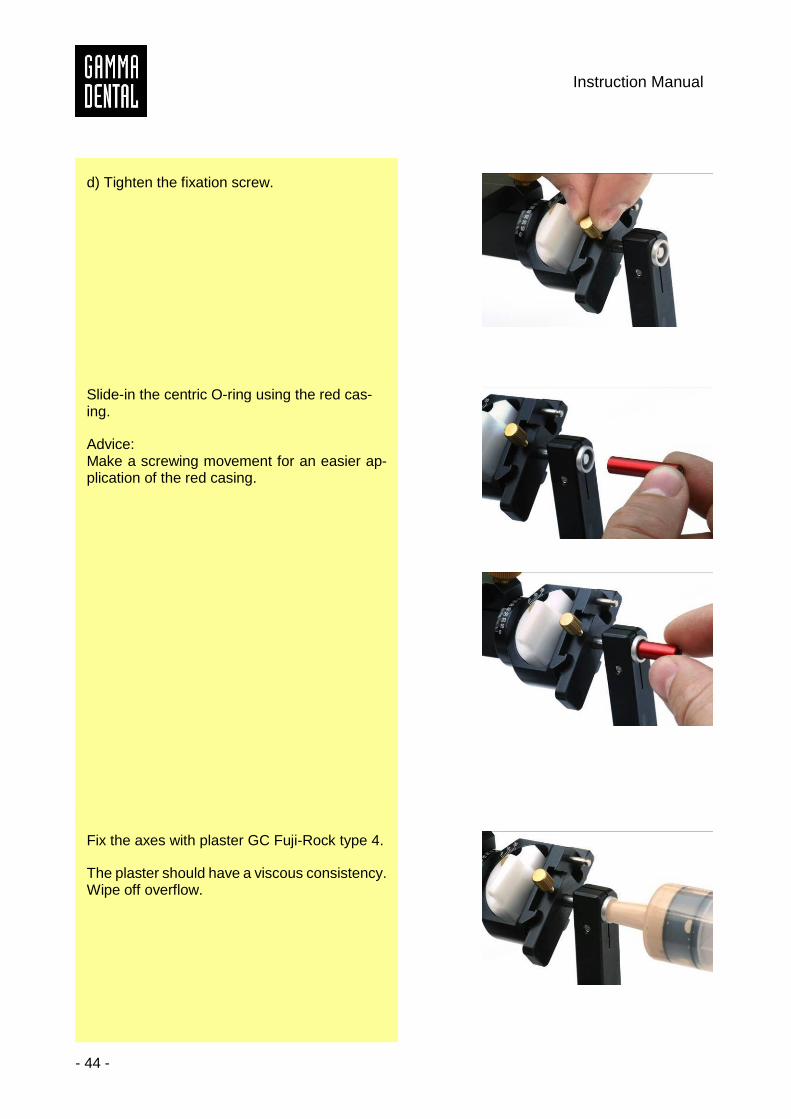
d) Tighten the fixation screw.
Slide-in the centric O-ring using the red cas-ing.
Advice: Make a screwing movement for an easier ap-plication of the red casing.
Fix the axes with plaster GC Fuji-Rock type 4.
The plaster should have a viscous consistency. Wipe off overflow.
Reference SL Articulator and Face Bow Systems
- 45 -
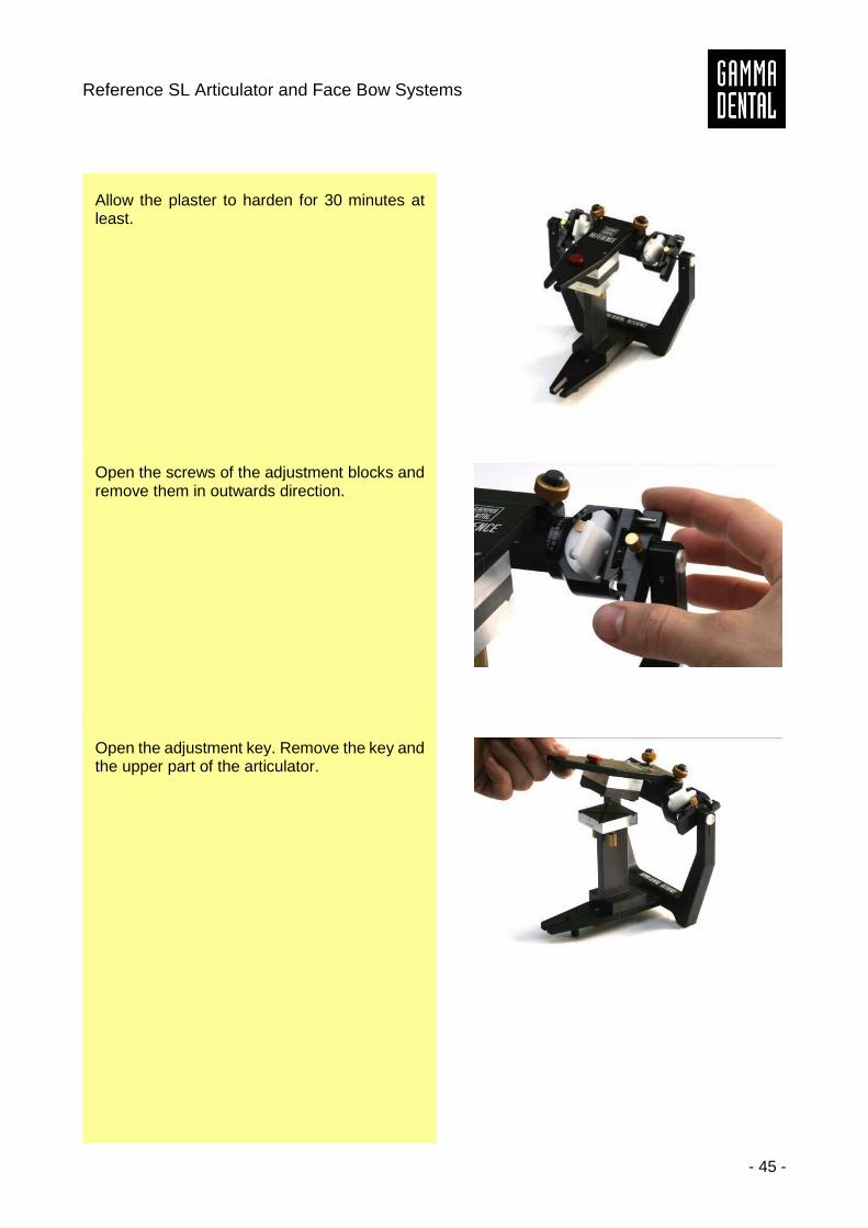
Allow the plaster to harden for 30 minutes at least.
Open the screws of the adjustment blocks and remove them in outwards direction.
Open the adjustment key. Remove the key and the upper part of the articulator.
Instruction Manual
- 46 -
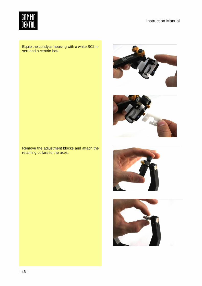
Equip the condylar housing with a white SCI in-sert and a centric lock.
Remove the adjustment blocks and attach the retaining collars to the axes.

Reference SL Articulator and Face Bow Systems
- 47 -
Fix the retaining collars.
Equip the articulator with the incisal table and incisal pin unit. Connect upper and lower sec-tion and close the centric lock.
Move the retaining collars to the centric locks and fix them with an Allen key from back and below.
Finished!
Instruction Manual
- 48 -
6 Curve of Spee Analyzer Set
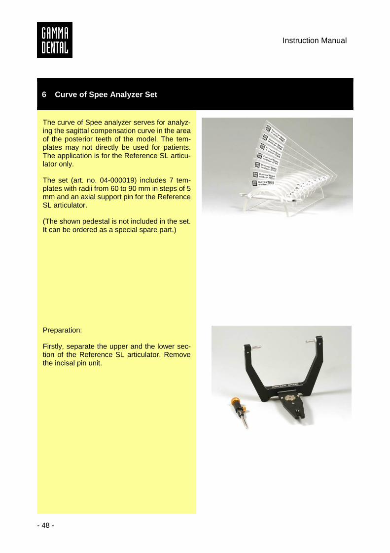
The curve of Spee analyzer serves for analyz-ing the sagittal compensation curve in the area of the posterior teeth of the model. The tem-plates may not directly be used for patients. The application is for the Reference SL articu-lator only.
The set (art. no. 04-000019) includes 7 tem-plates with radii from 60 to 90 mm in steps of 5 mm and an axial support pin for the Reference SL articulator.
(The shown pedestal is not included in the set. It can be ordered as a special spare part.)
Preparation:
Firstly, separate the upper and the lower sec-tion of the Reference SL articulator. Remove the incisal pin unit.
Reference SL Articulator and Face Bow Systems
- 49 -
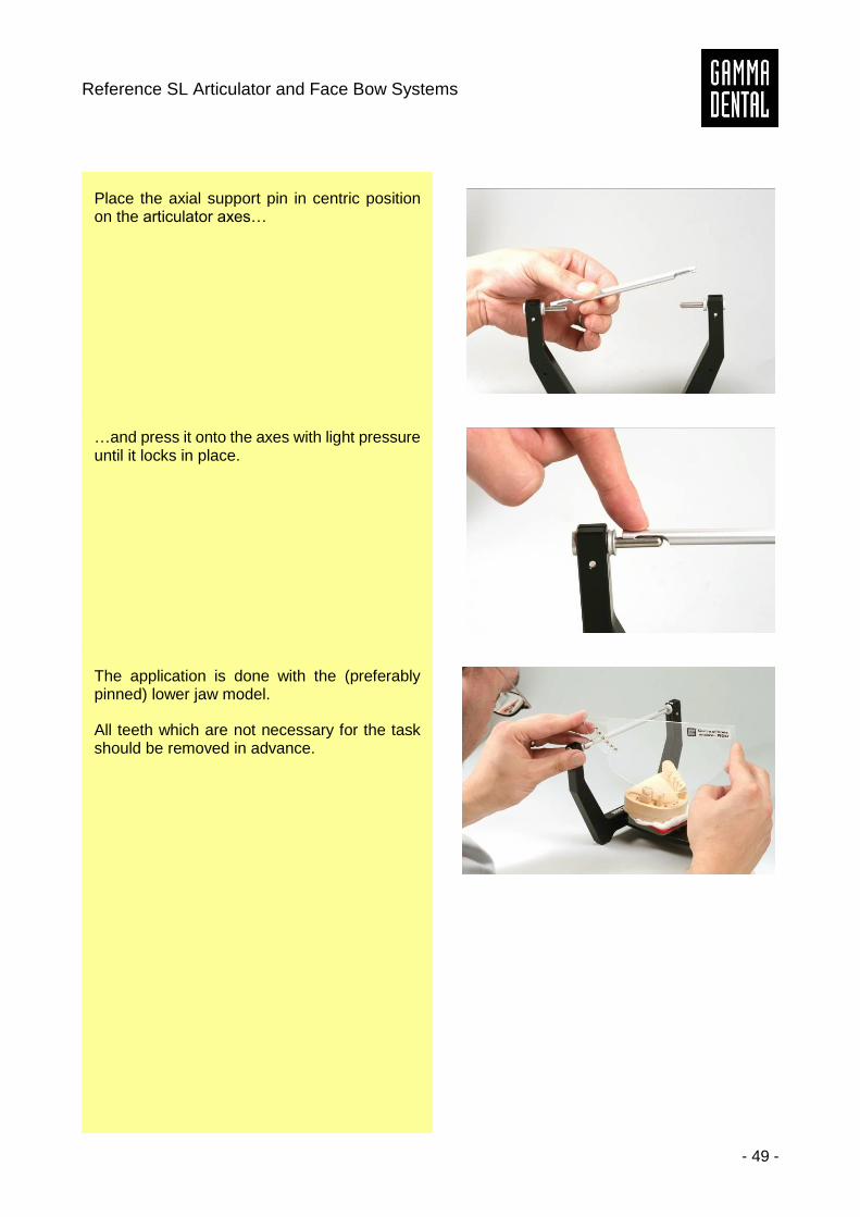
Place the axial support pin in centric position on the articulator axes…
…and press it onto the axes with light pressure until it locks in place.
The application is done with the (preferably pinned) lower jaw model.
All teeth which are not necessary for the task should be removed in advance.
Instruction Manual
- 50 -
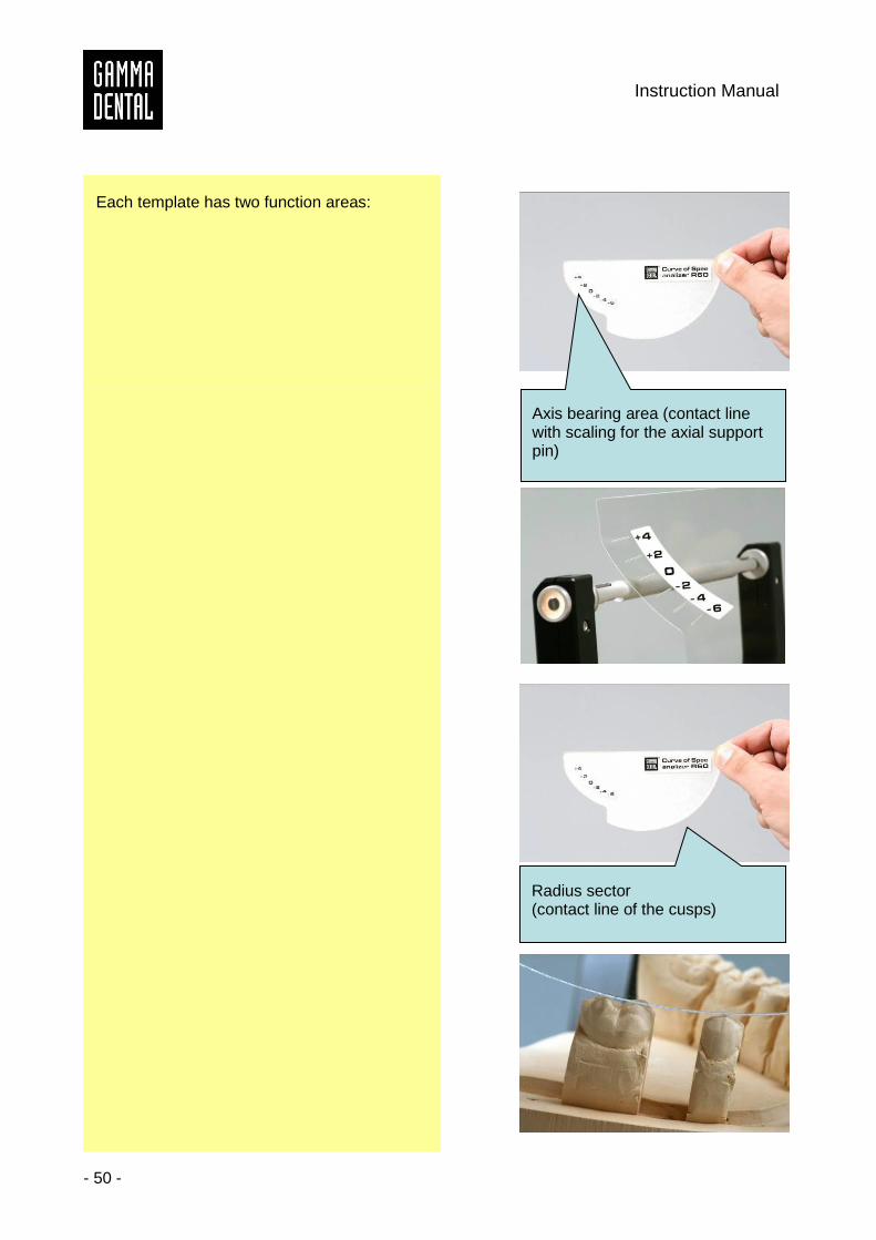
Each template has two function areas:
Axis bearing area (contact line with scaling for the axial support pin)
Radius sector (contact line of the cusps)
Reference SL Articulator and Face Bow Systems
- 51 -
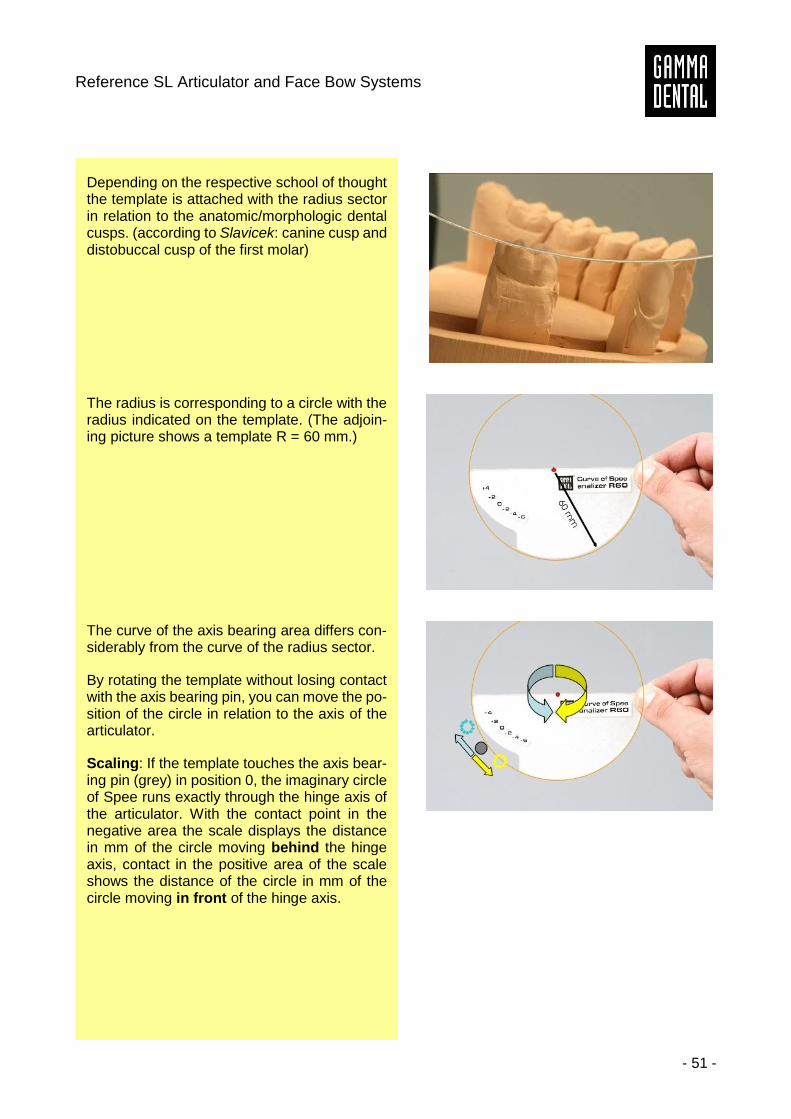
Depending on the respective school of thought the template is attached with the radius sector in relation to the anatomic/morphologic dental cusps. (according to Slavicek: canine cusp and distobuccal cusp of the first molar)
The radius is corresponding to a circle with the radius indicated on the template. (The adjoin-ing picture shows a template R = 60 mm.)
The curve of the axis bearing area differs con-siderably from the curve of the radius sector.
By rotating the template without losing contact with the axis bearing pin, you can move the po-sition of the circle in relation to the axis of the articulator.
Scaling: If the template touches the axis bear-ing pin (grey) in position 0, the imaginary circle of Spee runs exactly through the hinge axis of the articulator. With the contact point in the negative area the scale displays the distance in mm of the circle moving behind the hinge axis, contact in the positive area of the scale shows the distance of the circle in mm of the circle moving in front of the hinge axis.
Instruction Manual
- 52 -
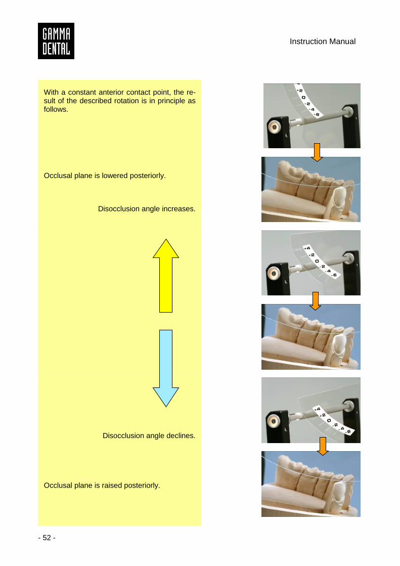
With a constant anterior contact point, the re-sult of the described rotation is in principle as follows.
Occlusal plane is lowered posteriorly.
Disocclusion angle increases.
Disocclusion angle declines.
Occlusal plane is raised posteriorly.
Reference SL Articulator and Face Bow Systems
- 53 -
The previously shown changes in direction nei-ther include the actual individual condylar guide inclination of the patient (CADIAX), nor the analysis based on cephalometric data (CA-DIAS).
These parameters should always be taken into account in analysis and planning.
Literature:
J.P. Re, C. Perez, A. Giraudeau,. P.Ager, A.El Zoghby, J.-D. Orthlieb
Reconstruction of the curve of Spee Stomatologie (2008) 105: 29-32
Instruction Manual
- 54 -
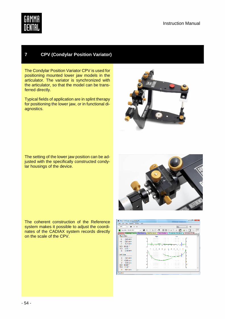
7 CPV (Condylar Position Variator)
The Condylar Position Variator CPV is used for positioning mounted lower jaw models in the articulator. The variator is synchronized with the articulator, so that the model can be trans-ferred directly.
Typical fields of application are in splint therapy for positioning the lower jaw, or in functional di-agnostics.
The setting of the lower jaw position can be ad-justed with the specifically constructed condy-lar housings of the device.
The coherent construction of the Reference system makes it possible to adjust the coordi-nates of the CADIAX system records directly on the scale of the CPV.
Reference SL Articulator and Face Bow Systems
- 55 -
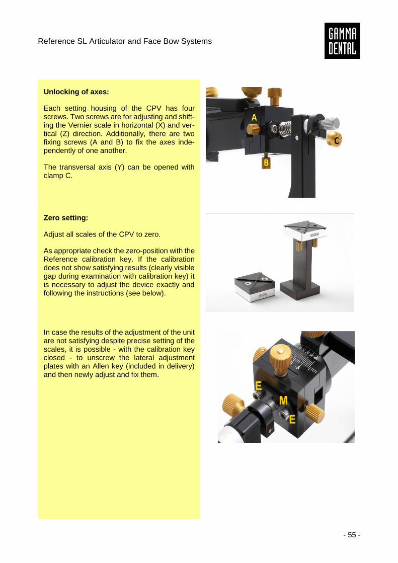
Unlocking of axes:
Each setting housing of the CPV has four screws. Two screws are for adjusting and shift-ing the Vernier scale in horizontal (X) and ver-tical (Z) direction. Additionally, there are two fixing screws (A and B) to fix the axes inde-pendently of one another.
The transversal axis (Y) can be opened with clamp C.
Zero setting:
Adjust all scales of the CPV to zero.
As appropriate check the zero-position with the Reference calibration key. If the calibration does not show satisfying results (clearly visible gap during examination with calibration key) it is necessary to adjust the device exactly and following the instructions (see below).
In case the results of the adjustment of the unit are not satisfying despite precise setting of the scales, it is possible - with the calibration key closed - to unscrew the lateral adjustment plates with an Allen key (included in delivery) and then newly adjust and fix them.
Instruction Manual
- 56 -
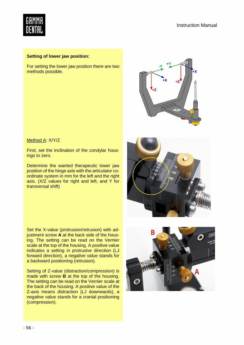
Setting of lower jaw position:
For setting the lower jaw position there are two methods possible.
Method A: X/Y/Z
First, set the inclination of the condylar hous-ings to zero.
Determine the wanted therapeutic lower jaw position of the hinge axis with the articulator co-ordinate system in mm for the left and the right axis. (X/Z values for right and left, and Y for transversal shift)
Set the X-value (protrusion/retrusion) with ad-justment screw A at the back side of the hous-ing. The setting can be read on the Vernier scale at the top of the housing. A positive value indicates a setting in protrusive direction (LJ forward direction), a negative value stands for a backward positioning (retrusion).
Setting of Z-value (distraction/compression) is made with screw B at the top of the housing. The setting can be read on the Vernier scale at the back of the housing. A positive value of the Z-axis means distraction (LJ downwards), a negative value stands for a cranial positioning (compression).
Reference SL Articulator and Face Bow Systems
- 57 -
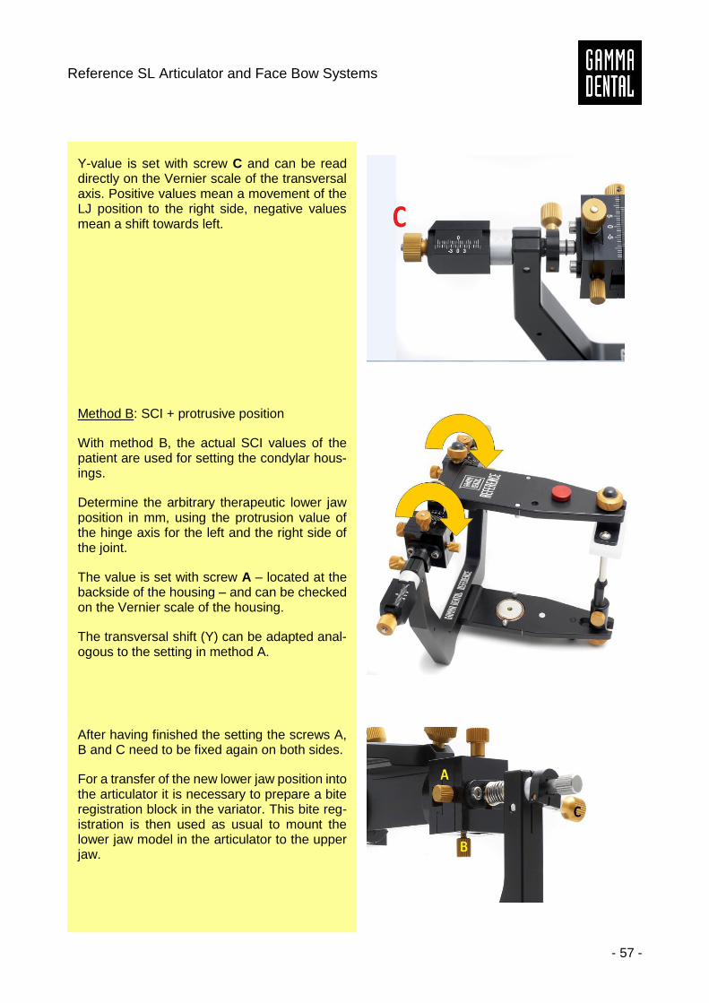
Y-value is set with screw C and can be read directly on the Vernier scale of the transversal axis. Positive values mean a movement of the LJ position to the right side, negative values mean a shift towards left.
Method B: SCI + protrusive position
With method B, the actual SCI values of the patient are used for setting the condylar hous-ings.
Determine the arbitrary therapeutic lower jaw position in mm, using the protrusion value of the hinge axis for the left and the right side of the joint.
The value is set with screw A – located at the backside of the housing – and can be checked on the Vernier scale of the housing.
The transversal shift (Y) can be adapted anal-ogous to the setting in method A.
After having finished the setting the screws A, B and C need to be fixed again on both sides.
For a transfer of the new lower jaw position into the articulator it is necessary to prepare a bite registration block in the variator. This bite reg-istration is then used as usual to mount the lower jaw model in the articulator to the upper jaw.
Instruction Manual
- 58 -
8 Maintenance and cleaning
Clean the Reference SL articulator system and face bow gently and without using solvents. For a long-lasting function of the articulator it is not necessary to use lubricants.
The instruments should not get in contact with strong acids, avoid cleaning it in an ultrasonic bath. Do not use corrosive liquids, scrubbing brushes, wire brushes or similar materials!
Only use cleaning agents suitable for disinfecting and cleaning light alloys. (The reaction times are listed in the manufacturer’s instruction.)
Sterilization must be carried out in an autoclave: 5 mins. at 134ºC, 20 mins. at 120ºC
Preparing for use:
Bite fork: Disinfect in a disinfecting tank or use disinfectant spray. Clean the registration material off the bite fork. If a thermoplastic material has been used, it is advisable to place the bite fork in a re-frigerator. The registration material is then easier to remove from the bite fork. Sterilize in an autoclave.
Glabella support: Spray the nasion with disinfectant. Wash off any residues under running water. May be auto-claved but is not absolutely essential.
Porus supports: Unscrew the porus supports and immerse them in disinfectant. The porus supports are best cleaned with a steam cleaner. To steam the hole, hold the nozzle of the steam cleaner in the acoustics hole and spray it clean. May be autoclaved but is not absolutely essential.

Reference SL Articulator and Face Bow Systems
- 59 -