Embed Size (px)
Citation preview

Animated LED Eyes: PART NO. 2171591
Time Required: 3 Hours Depending on Experience | Intermediate Level They're creepy! They're funny! They make you wonder if they're real! The luminous green eyes scan the room, blink, and if the optional PIR sensor is installed (purchased separately), they shoot forward if anyone walks by. An animation algorithm running in a micro-controller is directed by a pseudo-random number generator that is seeded every time the PIR sensor detects a warm body. The seeding by random events insures that the eye movement patterns rarely repeat. Get more than one and open a new dimension of fun as numerous pairs of eyes wonder independently until someone walks into the room, causing them all to snap forward in near unison as if to shout, "Who's there!?" It's a cool effect -- great for adding that extra degree of spook to your haunted house. A jumper is included that allows the eyes to run independent of the sensor (purchased separately), so they don't react to movement in the room. If more than one are set this way and then powered up simultaneously, all the eyes will move in unison -- at least for a while. Differences in timing will cause them to diverge, eventually, but a simultaneous power cycle is all that is needed to re-sync the eyes. Required tools and parts: Soldering iron Solder (.020 diameter or less preferred) Liquid flux Tweezers Wire cutters PIC24HJ12GP201-I/SO also a way to program it (such as a PICkit 2 or PICkit 3) Optional: Needle nosed pliers Lead forming tool Desolder braid Desolder Pump 90% Alcohol (Isopropynol or Denatured for cleaning flux) 45° bevel tip for soldering iron Enclosure Plastic cutting tool Hand drill or drill press
Push pin or ultra-fine point permanent marker #1 Philips Screwdriver Multimeter PIR sensor (Panasonic EKMC1601111 (white) or EKMC1601112 (black) or EKMC1601113 (pearl))
Bill of Materials:
Part No. Qty. Description
35991 1 Rectifier Diode, 1N4004
94001 1 Capacitor, 2.2µF, 16V
178511 9 Transistor, PN2222A
178520 10 Tansistor, PN2907A
545596 1 Capacitor, 1µF, 35V
545625 1 Capacitor, 10µF, 10V
38360 2 Transistor, 2N3904
151555 1 DC Power Jack, 2.1mm
109576 1 Header, 1x3, 0.1"
216187 1 Battery Holder, 4xAA with cover and switch
332672 1 Capacitor, 0.1µF, 100V
690443 2 Resistor, 18 Ω
690996 10 Resistor, 3.6 KΩ
691032 7 Resistor, 5.1 KΩ
152671 1 Shunt, shorting block, 0.1"
1323397 1 Regulator, LP2950ACZ-3.3
2005745 2 DOT Matrix Display, 5x7
2157167 1 Resistor, 10 KΩ
--- 1 PCB
--- 1 Instructions
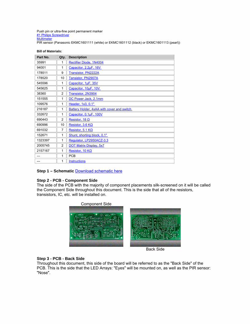
Step 1 – Schematic Download schematic here Step 2 - PCB - Component Side The side of the PCB with the majority of component placements silk-screened on it will be called the Component Side throughout this document. This is the side that all of the resistors, transistors, IC, etc. will be installed on.
Component Side
Back Side
Step 3 - PCB - Back Side Throughout this document, this side of the board will be referred to as the "Back Side" of the PCB. This is the side that the LED Arrays: "Eyes" will be mounted on, as well as the PIR sensor: "Nose".
Step 4 – Optional Enclosure If you plan to mount the completed PCB in an enclosure, then see the Enclosure steps at the end of this document. Depending on the technique used, you may need to prepare the enclosure before installing components on the PCB, because the PCB is also a template for marking positions for cutting and drilling. Step 5 - How to Solder SMD parts If you don't know how to solder SMD parts, watch this video: http://youtu.be/5uiroWBkdFY Step 6 - Install Bevel Tip in Soldering Iron If you have a bevel tip for your soldering iron, then install it on your iron (CAUTION: make sure the tip is cool before doing this and follow the manufactures instructions). After replacing the tip, turn the iron on so it will be heating up.
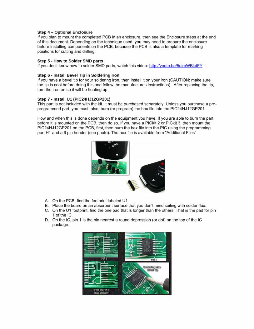
Step 7 - Install U1 (PIC24HJ12GP201) This part is not included with the kit. It must be purchased separately. Unless you purchase a pre-programmed part, you must, also, burn (or program) the hex file into the PIC24HJ12GP201. How and when this is done depends on the equipment you have. If you are able to burn the part before it is mounted on the PCB, then do so. If you have a PICkit 2 or PICkit 3, then mount the PIC24HJ12GP201 on the PCB, first, then burn the hex file into the PIC using the programming port H1 and a 6 pin header (see photo). The hex file is available from "Additional Files"
A. On the PCB, find the footprint labeled U1 B. Place the board on an absorbent surface that you don't mind soiling with solder flux. C. On the U1 footprint, find the one pad that is longer than the others. That is the pad for pin
1 of the IC. D. On the IC, pin 1 is the pin nearest a round depression (or dot) on the top of the IC
package.

E. Apply liquid solder flux to the longer pad, covering the pad and area around the pad.
Solder paste can also be used. If using solder paste, completely cover the pad and make sure (in the next step) to press the IC down, gently, so the pin(s) squish through the paste and rest on the pad (otherwise the IC might float off-center as the paste melts).
F. Using tweezers (or other such tool), place the IC on the PCB so that pin 1 coincides with the longer pad and that all the other pins also rest squarely on their pad.
G. Melt a small amount of solder on the bevel face of the soldering iron tip. If you don't have a bevel tip, then do your best to emulate the bevel tip instructions using whatever style of tip you do have.
H. Touch the face of the bevel tip to the longest pad making sure not to bump the IC. The
flux (applied in a previous step) will cause the solder to wick up to the IC pin and solder it in place. If this doesn't happen, slide the tip closer to the IC (again, making sure not to bump the IC). If this still fails to solder the pin, then, using tweezers, hold the IC in place and touch the face of the iron's bevel tip to pin1.
Note: if more than one pin is soldered in this process, don't worry. The goal is to immobilize the IC to make it easier to solder the remaining pins. If more than one pin is soldered, the better! Note: If after soldering, the IC is not square on the pads or is otherwise severely misaligned, then using tweezers, straighten the IC as you use the soldering iron to apply heat to the soldered pins. Do this quickly to avoid applying too much heat to the IC.
I. Turn the board around so you are working on the pins opposite from the one(s) you just soldered and then lay a length of solder wire over the pins and press the bevel face down on the solder so it melts onto the pins. Start at the end of the solder wire each time (the end will recede as the solder is melted onto the pins).
J. Do the same thing for the pins on the other side of the IC (18 pins in all).
Step 8 - Install U1 -- Alternate Soldering Technique
A. Lay a bead of solder flux paste over the pins on one side of the IC. Make sure it’s pure paste, not solder infused paste, both of which are referred to as solder paste.
B. Melt a liberal amount of solder onto the bevel face of the soldering iron tip.
C. Start at one end of the bead/row of IC pins and press the bevel face through the paste
bead down to the pins below so that part of the paste bead melts, taking care not to knock the IC off the pads. Some of the solder that's on the face of the bevel will melt onto the pins and the pad below.
D. Continue doing this until all of the pins are soldered to the pads on that side of the IC.
E. Do the same thing for the pins on the other side of the IC (18 pins in all).
Step 9 - Inspect U1 for solder flaws Look for solder bridges and unsoldered pin(s). If you find any, momentarily touch the flat part of the iron tip to the pin(s), once again. That should remove the bridge, or solder the pins, as needed. If the bridge persists, try again, or use a solder braid to wick the extra solder away from the pins. If the pins are still not properly soldered, try adding a little more solder.
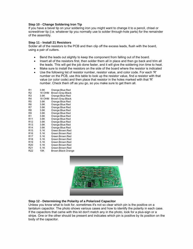
Step 10 - Change Soldering Iron Tip If you have a bevel tip on your soldering iron you might want to change it to a pencil, chisel or screwdriver tip (i.e. whatever tip you normally use to solder through-hole parts) for the remainder of the assembly. Step 11 - Install 21 Resistors Solder all of the resistors to the PCB and then clip off the excess leads, flush with the board, using a pair of cutters.
Bend the leads out slightly to keep the component from falling out of the board. Insert all of the resistors first, then solder them all in place and then go back and trim all
the leads. This will get the job done faster, and it will give the soldering iron time to heat. Make sure to install the resistors on the side of the board where the resistor is indicated Use the following list of resistor number, resistor value, and color code. For each 'R'
number on the PCB, use this table to look up the resistor value, find a resistor with that value (or color code) and then place that resistor in the holes marked with that 'R' number. Check them off as you go, so you make sure to get them all.
R1 3.6K Orange:Blue:Red R2 18 OHM Brown:Gray:Black R3 3.6K Orange:Blue:Red R4 18 OHM Brown:Gray:Black R5 3.6K Orange:Blue:Red R6 3.6K Orange:Blue:Red R7 3.6K Orange:Blue:Red R8 3.6K Orange:Blue:Red R9 3.6K Orange:Blue:Red R1 3.6K Orange:Blue:Red R11 3.6K Orange:Blue:Red R12 3.6K Orange:Blue:Red R13 3.6K Orange:Blue:Red R14 3.6K Orange:Blue:Red R15 5.1K Green:Brown:Red R16 5.1K Green:Brown:Red R17 5.1K Green:Brown:Red R18 5.1K Green:Brown:Red R19 5.1K Green:Brown:Red R20 5.1K Green:Brown:Red R21 5.1K Green:Brown:Red R22 10K Brown:Black:Orange
Step 12 - Determining the Polarity of a Polarized Capacitor Unless you know what to look for, sometimes it's not so clear which pin is the positive on a tantalum capacitor. The photo shows various cases and how to identify the polarity in each case. If the capacitors that came with this kit don't match any in the photo, look for a plus-sign or a stripe. One or the other should be present and indicates which pin is positive by its position on the body of the capacitor.
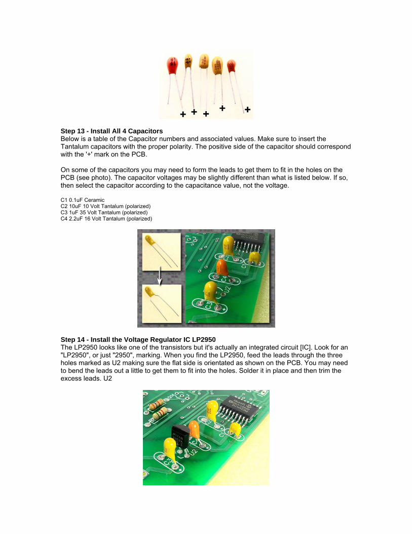
Step 13 - Install All 4 Capacitors Below is a table of the Capacitor numbers and associated values. Make sure to insert the Tantalum capacitors with the proper polarity. The positive side of the capacitor should correspond with the '+' mark on the PCB. On some of the capacitors you may need to form the leads to get them to fit in the holes on the PCB (see photo). The capacitor voltages may be slightly different than what is listed below. If so, then select the capacitor according to the capacitance value, not the voltage. C1 0.1uF Ceramic C2 10uF 10 Volt Tantalum (polarized) C3 1uF 35 Volt Tantalum (polarized) C4 2.2uF 16 Volt Tantalum (polarized)
Step 14 - Install the Voltage Regulator IC LP2950 The LP2950 looks like one of the transistors but it's actually an integrated circuit [IC]. Look for an "LP2950", or just "2950", marking. When you find the LP2950, feed the leads through the three holes marked as U2 making sure the flat side is orientated as shown on the PCB. You may need to bend the leads out a little to get them to fit into the holes. Solder it in place and then trim the excess leads. U2
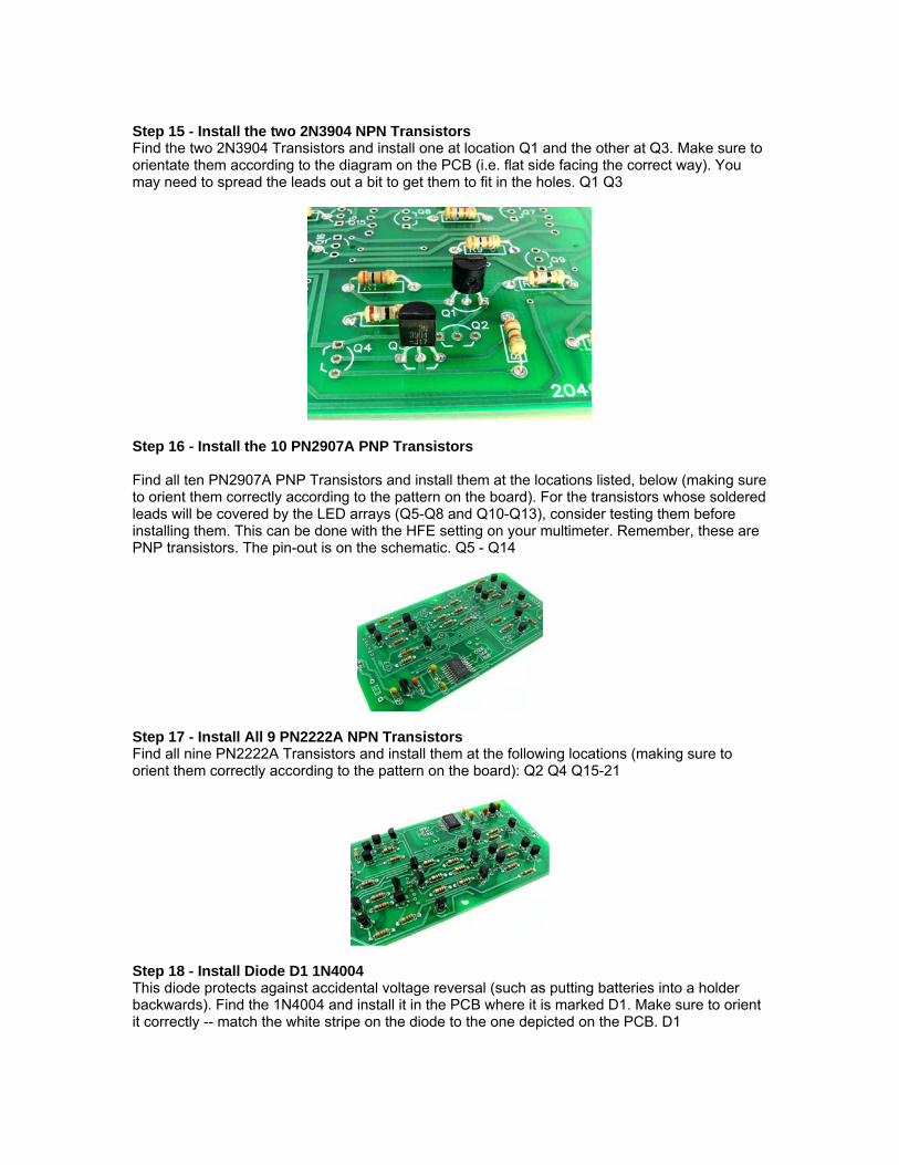
Step 15 - Install the two 2N3904 NPN Transistors Find the two 2N3904 Transistors and install one at location Q1 and the other at Q3. Make sure to orientate them according to the diagram on the PCB (i.e. flat side facing the correct way). You may need to spread the leads out a bit to get them to fit in the holes. Q1 Q3
Step 16 - Install the 10 PN2907A PNP Transistors Find all ten PN2907A PNP Transistors and install them at the locations listed, below (making sure to orient them correctly according to the pattern on the board). For the transistors whose soldered leads will be covered by the LED arrays (Q5-Q8 and Q10-Q13), consider testing them before installing them. This can be done with the HFE setting on your multimeter. Remember, these are PNP transistors. The pin-out is on the schematic. Q5 - Q14
Step 17 - Install All 9 PN2222A NPN Transistors Find all nine PN2222A Transistors and install them at the following locations (making sure to orient them correctly according to the pattern on the board): Q2 Q4 Q15-21
Step 18 - Install Diode D1 1N4004 This diode protects against accidental voltage reversal (such as putting batteries into a holder backwards). Find the 1N4004 and install it in the PCB where it is marked D1. Make sure to orient it correctly -- match the white stripe on the diode to the one depicted on the PCB. D1
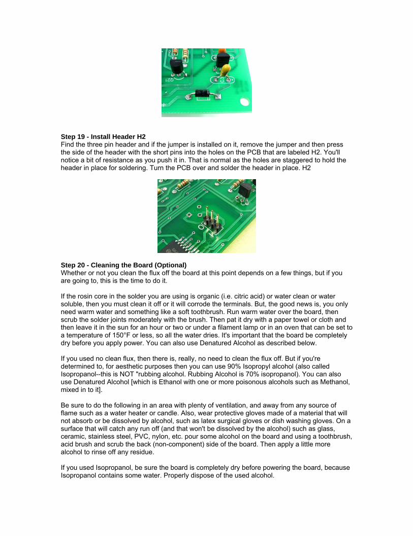
Step 19 - Install Header H2 Find the three pin header and if the jumper is installed on it, remove the jumper and then press the side of the header with the short pins into the holes on the PCB that are labeled H2. You'll notice a bit of resistance as you push it in. That is normal as the holes are staggered to hold the header in place for soldering. Turn the PCB over and solder the header in place. H2
Step 20 - Cleaning the Board (Optional) Whether or not you clean the flux off the board at this point depends on a few things, but if you are going to, this is the time to do it. If the rosin core in the solder you are using is organic (i.e. citric acid) or water clean or water soluble, then you must clean it off or it will corrode the terminals. But, the good news is, you only need warm water and something like a soft toothbrush. Run warm water over the board, then scrub the solder joints moderately with the brush. Then pat it dry with a paper towel or cloth and then leave it in the sun for an hour or two or under a filament lamp or in an oven that can be set to a temperature of 150°F or less, so all the water dries. It's important that the board be completely dry before you apply power. You can also use Denatured Alcohol as described below. If you used no clean flux, then there is, really, no need to clean the flux off. But if you're determined to, for aesthetic purposes then you can use 90% Isopropyl alcohol (also called Isopropanol--this is NOT "rubbing alcohol. Rubbing Alcohol is 70% isopropanol). You can also use Denatured Alcohol [which is Ethanol with one or more poisonous alcohols such as Methanol, mixed in to it]. Be sure to do the following in an area with plenty of ventilation, and away from any source of flame such as a water heater or candle. Also, wear protective gloves made of a material that will not absorb or be dissolved by alcohol, such as latex surgical gloves or dish washing gloves. On a surface that will catch any run off (and that won't be dissolved by the alcohol) such as glass, ceramic, stainless steel, PVC, nylon, etc. pour some alcohol on the board and using a toothbrush, acid brush and scrub the back (non-component) side of the board. Then apply a little more alcohol to rinse off any residue. If you used Isopropanol, be sure the board is completely dry before powering the board, because Isopropanol contains some water. Properly dispose of the used alcohol.
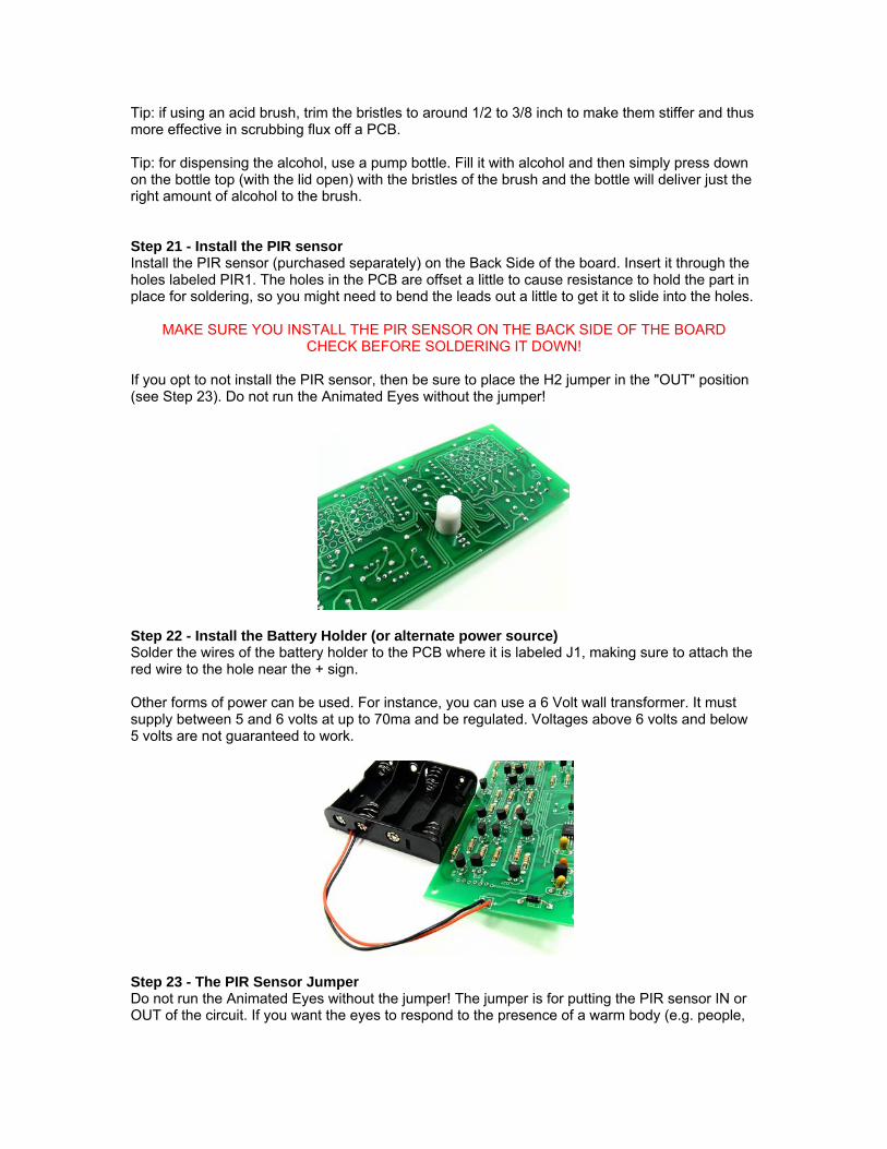
Tip: if using an acid brush, trim the bristles to around 1/2 to 3/8 inch to make them stiffer and thus more effective in scrubbing flux off a PCB. Tip: for dispensing the alcohol, use a pump bottle. Fill it with alcohol and then simply press down on the bottle top (with the lid open) with the bristles of the brush and the bottle will deliver just the right amount of alcohol to the brush. Step 21 - Install the PIR sensor Install the PIR sensor (purchased separately) on the Back Side of the board. Insert it through the holes labeled PIR1. The holes in the PCB are offset a little to cause resistance to hold the part in place for soldering, so you might need to bend the leads out a little to get it to slide into the holes.
MAKE SURE YOU INSTALL THE PIR SENSOR ON THE BACK SIDE OF THE BOARD CHECK BEFORE SOLDERING IT DOWN!
If you opt to not install the PIR sensor, then be sure to place the H2 jumper in the "OUT" position (see Step 23). Do not run the Animated Eyes without the jumper!
Step 22 - Install the Battery Holder (or alternate power source) Solder the wires of the battery holder to the PCB where it is labeled J1, making sure to attach the red wire to the hole near the + sign. Other forms of power can be used. For instance, you can use a 6 Volt wall transformer. It must supply between 5 and 6 volts at up to 70ma and be regulated. Voltages above 6 volts and below 5 volts are not guaranteed to work.
Step 23 - The PIR Sensor Jumper Do not run the Animated Eyes without the jumper! The jumper is for putting the PIR sensor IN or OUT of the circuit. If you want the eyes to respond to the presence of a warm body (e.g. people,

animals, etc.) then place the jumper across the two pins nearest the I (I for In). Otherwise, place it across the two pins nearest the O (O for Out) and the eyes will ignore any movements.
Note: a really cool effect can be achieved with two or more Animated LED Eyes kits (the more the better). When there's more than one set of eyes in a room, they will each follow different patterns (the eyes will tend to look in different directions) -- until someone walks into the room, in which case the eyes will all look forward. It's a really cool effect, especially when there are a lot of them running at once in a dark room! Great for adding a spooky touch to Halloween displays. The eye movements are determined by a pseudo-random algorithm, so they follow the same pattern when first powered up, BUT every time the PIR sensor is triggered, a number is acquired from an internal counter that is used to seed the random number generator, so after that, a whole new pattern is generated. Even if there are several pairs of eyes in the room, they will be triggered at slightly different times, and thus will be seeded differently and will, after that, behave differently. Step 24 - Installation of LED Arrays ("Eyes") Check all the solder joints that will be covered by the eyes. Make sure that transistors Q5, Q6, Q7, Q8, Q10, Q11, Q12 and Q13, as well as Resistors R7, R8, R12 and R13 are properly installed and all of their leads are soldered and trimmed flush with the board. Also, look for solder bridges on any of these components. Hold the PCB up to a bright light and examine the traces with your eyes, making sure there are no breaks in the traces. And/or, use a continuity tester to check the continuity of every trace that will be hidden by the LED arrays. Also, check the continuity of all pads that will be covered by the arrays that also provide a path, for a trace, to the other side of the PCB. If one of these is not plated through, you want to discover it before the Arrays are soldered down. If any of them show open continuity run a wire from the trace on one side of the board to the continuation of the trace on the other side of the board. If possible, do this away from the footprint of the LED array. For the next step, install the jumper on the 3-pin header (H1) in the In position. This will cause the eyes to always look forward whenever the PIR sensor is triggered. Step 25 - Test the Eyes Before Soldering Them in Place This is very important, because once the LED arrays are soldered in place, they're very difficult to remove (though, it can be done with a hot air rework station). Make sure the jumper is installed on H1 in the In position (see step #24, last paragraph, if you're unsure). With the Back Side of the PCB facing up, so that the silk-screened diagrams for LA1, LA2 and PIR1 are showing, insert one of the LED arrays into the holes marked LA1. It's important
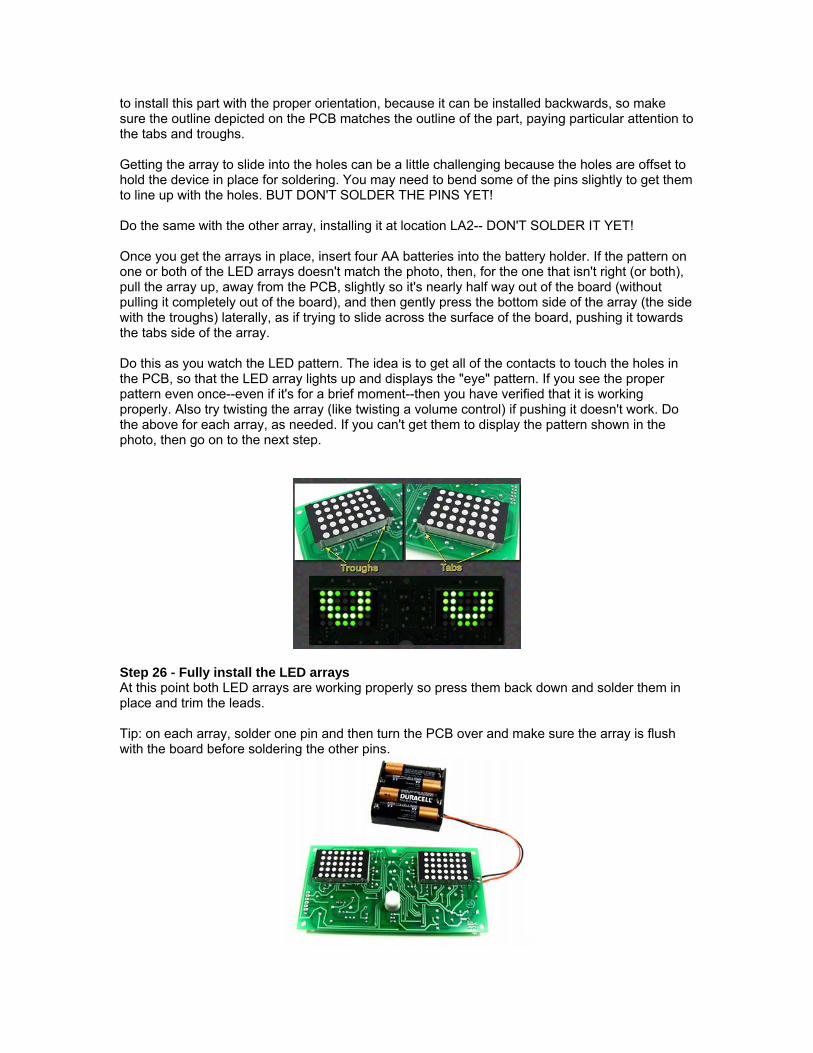
to install this part with the proper orientation, because it can be installed backwards, so make sure the outline depicted on the PCB matches the outline of the part, paying particular attention to the tabs and troughs. Getting the array to slide into the holes can be a little challenging because the holes are offset to hold the device in place for soldering. You may need to bend some of the pins slightly to get them to line up with the holes. BUT DON'T SOLDER THE PINS YET! Do the same with the other array, installing it at location LA2-- DON'T SOLDER IT YET! Once you get the arrays in place, insert four AA batteries into the battery holder. If the pattern on one or both of the LED arrays doesn't match the photo, then, for the one that isn't right (or both), pull the array up, away from the PCB, slightly so it's nearly half way out of the board (without pulling it completely out of the board), and then gently press the bottom side of the array (the side with the troughs) laterally, as if trying to slide across the surface of the board, pushing it towards the tabs side of the array. Do this as you watch the LED pattern. The idea is to get all of the contacts to touch the holes in the PCB, so that the LED array lights up and displays the "eye" pattern. If you see the proper pattern even once--even if it's for a brief moment--then you have verified that it is working properly. Also try twisting the array (like twisting a volume control) if pushing it doesn't work. Do the above for each array, as needed. If you can't get them to display the pattern shown in the photo, then go on to the next step.
Step 26 - Fully install the LED arrays At this point both LED arrays are working properly so press them back down and solder them in place and trim the leads. Tip: on each array, solder one pin and then turn the PCB over and make sure the array is flush with the board before soldering the other pins.

Step 27 - Testing the PIR sensor Install the H2 jumper so it's shorting the pins closest the silk-screened I and then hold very still (and I mean VERY still-the PIR sensor is very sensitive). When the eyes wander away from center, wave your hand in front of the PIR sensor and watch if the eyes come back to center. Try this several times to make sure it wasn't a random coincidence. If the eyes don't come back to center when you wave your hand in front of the sensor then go to section labeled Troubleshooting the PIR Sensor. Step 28 - Troubleshooting - try this first Examine the board for missing parts, unsoldered parts, bad solder joints (pay particular attention to the leads on U1, it's common for one or more of the SMD leads to not have soldered properly). Then, check for solder bridges or shorts (again this is most common on U1 - use a magnifying glass if necessary and look closely between the pins). Examine the board with a bright light held above the board and then with it held under the board, looking, again, for solder bridges, open traces, bad solder joints and anything amiss. Check all of the polarized capacitors to make sure they are inserted in the PCB with the proper polarity. The positive side of the capacitor should correspond to the + marked on the PCB (if needed, review Step 12 . Determining the Polarity of a Polarized Capacitor). Check all of the transistors to make sure they are inserted in the proper orientation and that the correct part number is in the correct place. Pay special attention to the placement of PNP vs NPN Transistors (the PN2222A and the 2N3904 are NPN Transistors and the 2N2907A Transistors are PNP). Review steps 15, 16 and 17, as needed. Check that the LED Arrays are inserted properly. Make sure the tabs on the arrays are aligned with the tabs depicted on the PCB (if you aren't sure what a tab is, see the photo in Step 25). It's very unlikely, but one or more of the PCB traces could be either open or shorted. With a bright light under the board, carefully examine each trace, especially where there are adjacent traces in close proximity. If you have a PICkit2 or PICkit3, connect it to H1 (press a 6-pin header into the H1 holes and then plug the PICkit into the top of the header making sure that pin 1 on the PICkit aligns with the longer pad (also, pin 6 is the one not connected to anything). Then see if you can detect the presence of the PIC25HJ12CP201 (MAKE SURE NOT TO ERASE THE PROGRAM CONTAINED WITHIN IT!). If the PICkit won't detect U1, try applying GENTLE pressure against the side of the PICkit to lever the 6-pin header against the metal in the PCB holes and then, while holding that pressure, try detecting the PIC again (e.g. Tools/Check Communication). If it still won't detect the PIC, then there might be a solder bridge or unsoldered pin or even an open or shorted trace between U1 and H1. Also check R9 and R14 both should be 3.6K resistors. And check that R16 is a 5.1K resistor. There is also the possibility that the PIC is not programmed. If you have exhausted all other possibilities, then acquire another PIC and replace it. If you don't have SMD rework tools, then get a ChipQuik SMD removal kit. To see how it works, search for ChipQuik on YouTube. Tip: use the photo of the component side of the PCB at the beginning of this document to locate the resistors (because the designators printed on the board are covered by the resistors when they are installed). Step 29 - Troubleshooting - Symptom/Possible Cause Matrix Symptom 1: Nothing happens. The eyes don't light up.
A. Batteries/Power source installed/connected backwards

B. Battery Holder wires installed backwards. The red wire should be connected to the pad with the '+' (plus sign).
C. D1 backwards (the white band on the diode should be on the side of the part that faces away from J1 and towards U1).
D. U2 bad or installed backwards (the curved side of the part should be facing U1). E. U2 wrong part -- it's easy to confuse the LP2950 with one of the transistors. Since there
are three versions of the LP2950 (3.0V, 3.3V and 5.0V) it's also possible that the LP2950 is the wrong voltage. Check the printing on the part. There should be a 3.3 and not a 3.0 or a 5.0.
F. C2, C3 or C4 installed backwards (the positive side of the part should be facing the '+' mark on the PCB).
G. C3 the wrong value. It should be 1uF with a voltage of at least 25V (typically 35V). H. C4 the wrong value. It should be 2.2uF (typically 16V). I. C2 the wrong value. It should be 10uF with a voltage of 6V or higher – typically 10V). J. C1 shorted (look for a solder bridge and if not found, try removing C1 [C1 is actually
optional and in most cases the circuit will run fine without it but if the eyes become erratic, suspect the lack of C1 before anything else).
K. VDD shorted to ground. Use a volt meter to verify that the voltage at pin 18 on U1 is 3.3 volts +/-1%, if it's at or near 0 volts, then look for a solder bridge between the output of U2 and ground (center pin). Make sure that U2 is inserted correctly (it's orientation should match the diagram printed on the PCB) and that it has LP2950 printed on it.
L. It's possible that the PIC24HJ12GP201 wasn't programmed. Request a replacement use it to replace U1(make sure to request one that is programmed for this kit). If you don't have SMD rework tools, then get a SMD removal kit.
Symptom 2: One or more columns in one or both of the LED arrays are either always on or always off. Possible Causes:
A. Check transistors Q15 Q21 for solder bridges or bad solder joints or unsoldered leads. Check resistors R15 R21 for incorrect value should be 5.1K.
B. Using the schematic and photo of the two sides of the PCB, determine which transistor would cause the symptom and replace it (if the pads for that transistor are covered by an LED Array, refer to step 31 (Replacing a Component Covered by an LED Array).
C. If only one column is affected, then the problem is either in the LED array itself or the pin for that column is not soldered or it could be a hole that is not plated-through. Use the schematic to figure out which LED Array pin is involved and try re-soldering it. To test for a hole not plated through, try shorting across the hole with a wire (it might not be the hole that the pin you located is in, it might be a different hole. Follow the trace that goes to the pin in question and try shorting across any hole (whether for a component pin or for a via) that is inline with that trace. You will need to use the schematic and/or the photos of the two sides of the PCB to figure out where to connect the two ends of the wire (especially if the hole is under one of the LED Arrays. Also consider that it could be more than one hole and try using the wire to bypass ALL of the holes. If that fixes the problem, then solder the wire in place. If not, then it's probably the LED Array, you'll have to replace it.
Symptom 3: One or more rows in one or both of the LED arrays are either always on or always off. Possible Causes:
A. Check transistors Q5 Q14 for solder bridges or bad solder joints or unsoldered leads. Check resistors R5 R14 for incorrect value should be 3.6K.
B. Using the schematic and photo of the two sides of the PCB, determine which transistor would cause the symptom and replace it.

C. It could also be the LED array itself or that the pin for that row is not soldered or it could be a hole that is not plated-through. Follow the diagnostic, described above, for an affected column (Symptom 2.C).
Step 30 - Troubleshooting the PIR Sensor
A. Check that the PIR sensor is installed on the board.
B. Use an ohmmeter or continuity tester to check that the jumper is actually shorting the pins. You can also test this by shorting the pins with an alligator clip and then re-testing the PIR sensor.
C. Check the pads where the PIR is soldered to the board. Look for solder bridges (very
unlikely) and lack of solder (as in not soldered or poorly soldered). Remove any solder bridges and/or re-solder any pads that need attention, and then re-test the PIR sensor.
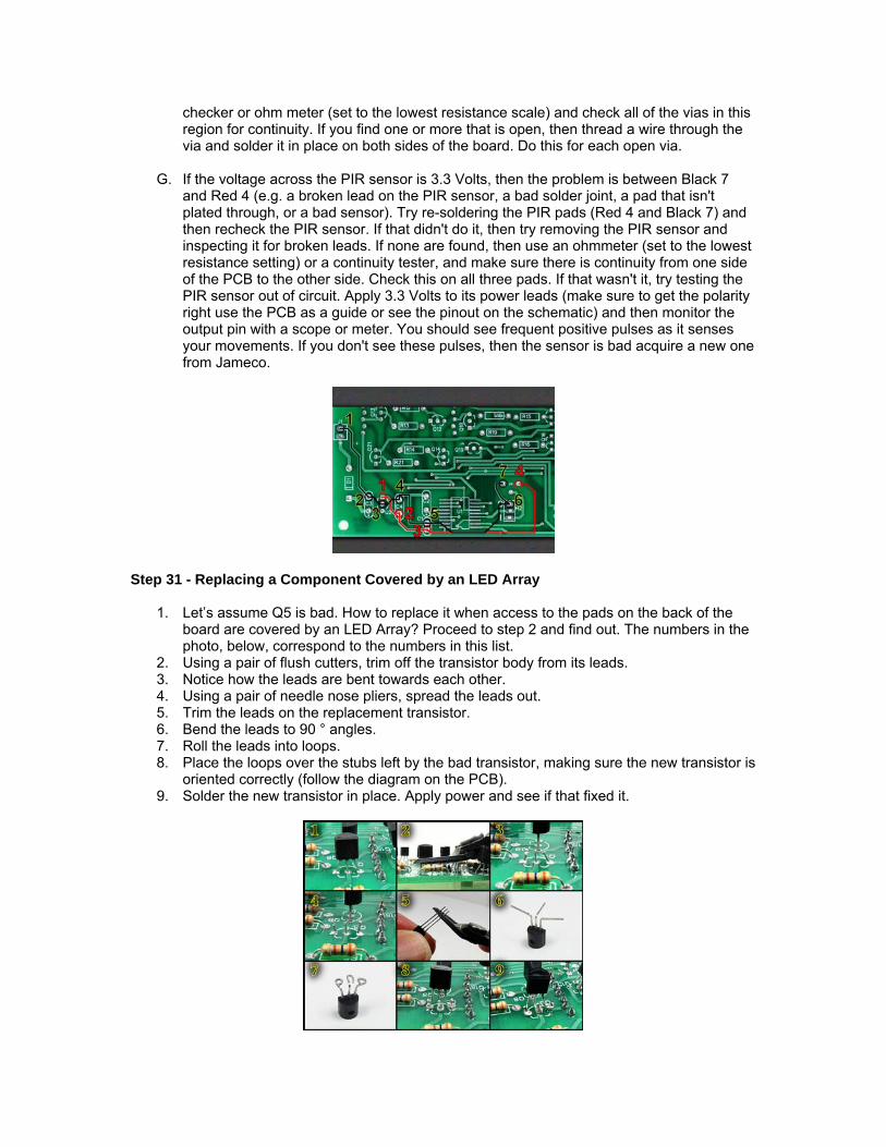
D. In the photo, the paths of positive and negative power are highlighted (red for positive
and black for negative) and the pads along those paths are circled and numbered. The numbering scheme goes like this: the negative path starts with "black 1" where the black battery wire is attached to the PCB and ends with "black 7" at the PIR sensor. The positive path starts with red 1 at the output of the LP2950 regulator and ends with red 4 at the PIR sensor. With a voltmeter (or multimeter set to DC Volts) measure from Black 7 [negative probe], to Red 4 [positive probe]. This is the voltage across the PIR sensor's supply leads and should read approx. 3.3 Volts (+/- 0.05%). If it does read 3.3 Volts, proceed to step G.
E. If the voltage is less than 3.0 Volts but not zero, then something is either loading down
the LP2950 regulator, or it's malfunctioning or it's the wrong part. FYI: the minimum voltage on the PIR sensor is specified to run at is 3.0 Volts. If the voltage IS zero, then proceed to Step F. If you used solder with water cleanable flux then flux residue could be causing this, or there could be water on the board somewhere(the most likely place is under U1). Try placing the board in heat for an hour or two. This could be in the sun, under a lamp that has a filament bulb (taking care to not let the board get too hot), or in an oven that you can set to 140°F or less. If that wasn't it, try replacing U2 (LP2950). Make sure you replace it with an LP2950ACZ3.3. If the low voltage condition persists, then all that is left is U1 (the PIC microcontroller), acquire a replacement. Make sure you get one programmed for this kit.
F. If the voltage across the PIR is zero, then it could be a short, an open trace or U2 could be malfunctioning. Check the voltage from Red 1 to Black 3. If it is also zero, then suspect either a short, or a bad U2. If it's 3.3 volts, then there's an open trace. With the negative probe of your meter at Black 3, check each of the pads circled red, starting with Red 2. If you get all the way to Red 4 and the voltage is still 3.3, then with the positive probe still on Red 4, begin measuring the voltages along the negative trace starting at Black 4, then Black 5, etc. If you get to Black 7 and the voltage is still 3.3, then either there's an intermittent open, or you made an error while testing start over. If the voltage went to zero while probing for an open trace, then the open is between the last pad you tested and the pad before that. If there's a trace in that region that transitions from one side of the board to the other, then it's possible that the hole that provides that transition is not fully plated through. There are two cases where a trace transitions from one side of the board to the other: a "pad" (which will likely have a through hole part installed in it). a via (which is just a plated-through hole to achieve the transition from one side of the PCB to the other). Inspect the two drilled pads in the region of the open for lack of solder from the part lead to the pad. Check this on both sides of the board. If you find such a case, apply solder to the lead until it IS soldered to the pad. To check the vias, use a continuity
checker or ohm meter (set to the lowest resistance scale) and check all of the vias in this region for continuity. If you find one or more that is open, then thread a wire through the via and solder it in place on both sides of the board. Do this for each open via.
G. If the voltage across the PIR sensor is 3.3 Volts, then the problem is between Black 7
and Red 4 (e.g. a broken lead on the PIR sensor, a bad solder joint, a pad that isn't plated through, or a bad sensor). Try re-soldering the PIR pads (Red 4 and Black 7) and then recheck the PIR sensor. If that didn't do it, then try removing the PIR sensor and inspecting it for broken leads. If none are found, then use an ohmmeter (set to the lowest resistance setting) or a continuity tester, and make sure there is continuity from one side of the PCB to the other side. Check this on all three pads. If that wasn't it, try testing the PIR sensor out of circuit. Apply 3.3 Volts to its power leads (make sure to get the polarity right use the PCB as a guide or see the pinout on the schematic) and then monitor the output pin with a scope or meter. You should see frequent positive pulses as it senses your movements. If you don't see these pulses, then the sensor is bad acquire a new one from Jameco.
Step 31 - Replacing a Component Covered by an LED Array
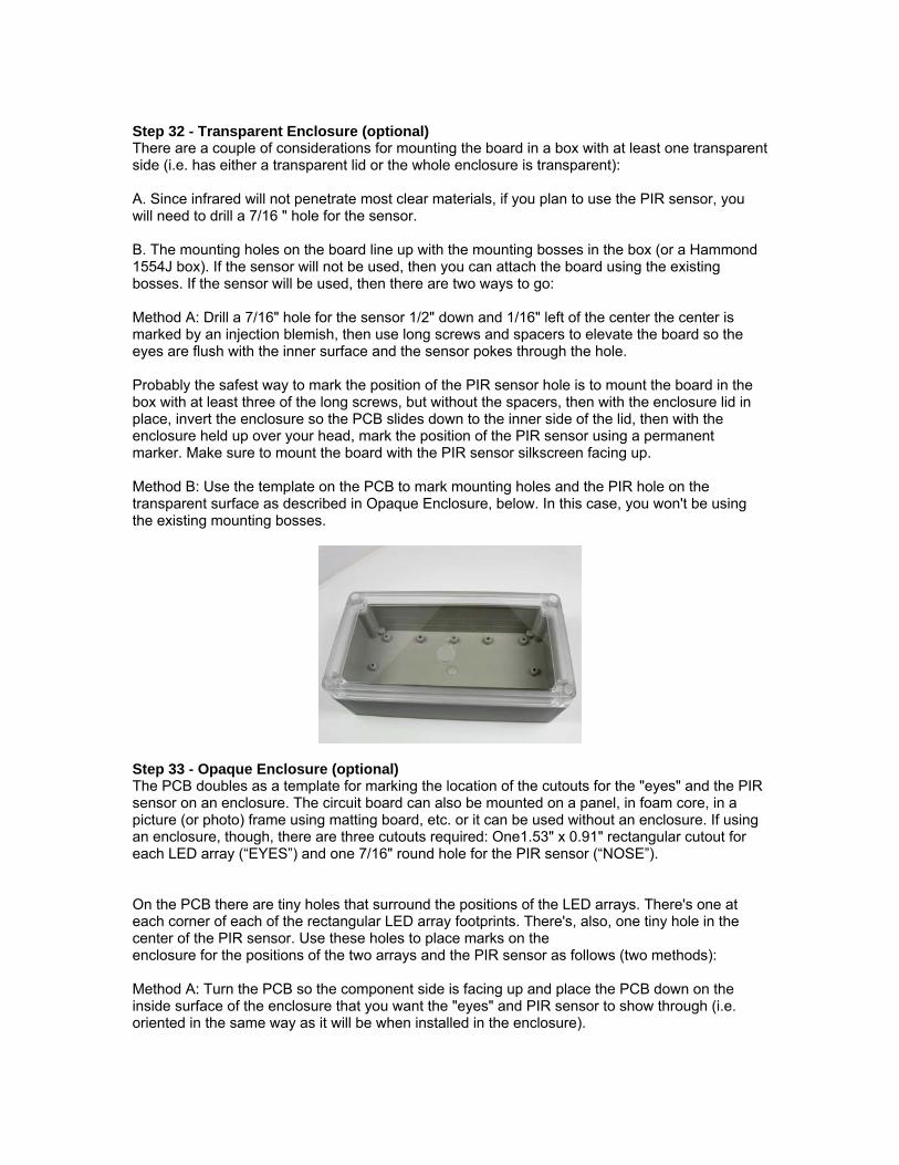
1. Let’s assume Q5 is bad. How to replace it when access to the pads on the back of the board are covered by an LED Array? Proceed to step 2 and find out. The numbers in the photo, below, correspond to the numbers in this list.
2. Using a pair of flush cutters, trim off the transistor body from its leads. 3. Notice how the leads are bent towards each other. 4. Using a pair of needle nose pliers, spread the leads out. 5. Trim the leads on the replacement transistor. 6. Bend the leads to 90 ° angles. 7. Roll the leads into loops. 8. Place the loops over the stubs left by the bad transistor, making sure the new transistor is
oriented correctly (follow the diagram on the PCB). 9. Solder the new transistor in place. Apply power and see if that fixed it.
Step 32 - Transparent Enclosure (optional) There are a couple of considerations for mounting the board in a box with at least one transparent side (i.e. has either a transparent lid or the whole enclosure is transparent): A. Since infrared will not penetrate most clear materials, if you plan to use the PIR sensor, you will need to drill a 7/16 " hole for the sensor. B. The mounting holes on the board line up with the mounting bosses in the box (or a Hammond 1554J box). If the sensor will not be used, then you can attach the board using the existing bosses. If the sensor will be used, then there are two ways to go: Method A: Drill a 7/16" hole for the sensor 1/2" down and 1/16" left of the center the center is marked by an injection blemish, then use long screws and spacers to elevate the board so the eyes are flush with the inner surface and the sensor pokes through the hole. Probably the safest way to mark the position of the PIR sensor hole is to mount the board in the box with at least three of the long screws, but without the spacers, then with the enclosure lid in place, invert the enclosure so the PCB slides down to the inner side of the lid, then with the enclosure held up over your head, mark the position of the PIR sensor using a permanent marker. Make sure to mount the board with the PIR sensor silkscreen facing up. Method B: Use the template on the PCB to mark mounting holes and the PIR hole on the transparent surface as described in Opaque Enclosure, below. In this case, you won't be using the existing mounting bosses.
Step 33 - Opaque Enclosure (optional) The PCB doubles as a template for marking the location of the cutouts for the "eyes" and the PIR sensor on an enclosure. The circuit board can also be mounted on a panel, in foam core, in a picture (or photo) frame using matting board, etc. or it can be used without an enclosure. If using an enclosure, though, there are three cutouts required: One1.53" x 0.91" rectangular cutout for each LED array (“EYES”) and one 7/16" round hole for the PIR sensor (“NOSE”). On the PCB there are tiny holes that surround the positions of the LED arrays. There's one at each corner of each of the rectangular LED array footprints. There's, also, one tiny hole in the center of the PIR sensor. Use these holes to place marks on the enclosure for the positions of the two arrays and the PIR sensor as follows (two methods): Method A: Turn the PCB so the component side is facing up and place the PCB down on the inside surface of the enclosure that you want the "eyes" and PIR sensor to show through (i.e. oriented in the same way as it will be when installed in the enclosure).

Method B: With the back side of the PCB facing up, place the PCB down on the outside enclosure surface that you want the "eyes" and PIR sensor to be visible from (i.e. oriented in the same way as it will be when installed within the enclosure). The drawback of doing it this way, as opposed to method A (above) is the inability to see possible obstructions within the enclosure, such as screw posts and mounting bosses, so be sure to take that into account. Using method A or B get the PCB into the position that you want it to be on final assembly. Hold it there while you mark one of the corner mounting holes (i.e. screw hole). Do this by tracing the inner circumference of the hole, either with a fine-tip marker or with a push pin or similar marking device. Lift the PCB and then using a center punch and hammer, tap a poc mark in the center of the circle. Use appropriate force for the material the enclosure is made of. If soft plastic use minimal force. If aluminum, tap harder. Drill a 1/8" hole at the point you just marked. With the #40 bolt and nut, fasten the board to the enclosure: to the inside if using method A and to the outside if using method B. Now mark and tap the hole at the opposite corner of the board. Drill a 1/8" hole there and use another #40 bolt and nut to secure the board on its opposite corner (where the new hole is). Now, with the board secured, mark on the enclosure surface, each of the LED Array corner positions and the PIR center position, using the little holes in the PCB (9 holes in all). If you want to use more than two bolts to secure the board, then mark the other screw holes (but in most cases, two corner fasteners should be enough). To make it easier to cut the LED Array holes strait, use a ruler with a marker or push pen or scratch awl to draw perimeter lines between the marks (see photo). This will, if done properly, result in two rectangles representing the positions of the two LED arrays. Use the marks to guide whatever tool you use to cut out the holes. For the "eyes", cut two rectangular holes. For the PIR sensor, use a 7/16" drill. If you have a drill press or milling machine, then you're all set. Just clamp your work and drill! But, if you need to do this by hand, then if the enclosure is plastic, wood or some other soft material, I would use a spade drill bit. A spade drill bit has a point that can be precisely placed on the mark. It also might not be a bad idea to drill a "pilot hole" (1/8" or smaller) to guide the larger drill, because even the point on a spade drill can drift, causing the resulting hole to be off-center.
Step 34 - How the Eyes Look In the Enclosure If you put the eyes in an enclosure, you might consider using an external power source (such as Jameco P/N 157340) and a power jack (such as Jameco P/N 151555), instead of using internal batteries, because of the inconvenience of having open the enclosure and un-mount the PCB in order to replace the batteries.

![Jameco Electronics - LED Shadow Clock Kit Assembly Guide[Bulbdial˜Assembly˜Guide] 2. Angle flush cutters 3. Electrical power You’ll also need some solder. Thin rosin-core solder](https://img.pdfslide.us/doc/110x75/606acec10699ac50e36b75c7/jameco-electronics-led-shadow-clock-kit-assembly-guide-bulbdialoeassemblyoeguide.jpg)