Embed Size (px)
Citation preview
Human Movement Science 8 (1989) 547-569 North-Holland
547
ANGULAR DISPLACEMENT OF TORSO DURING LIFTING: A SYSTEM COMPARISON OF TWO MEASURING METHODS *
Issachar GILAD Technion - Israel Institute of Technology, Haifa, Israel
Mark S. REDFERN, Don B. CHAFFIN and Seong N. BYUN University of Michigan, Ann Arbor, USA
Gilad, I., M.S. Redfern, D.B. Chaffin and S.N. Byun, 1989. Angular displacement of torso during lifting: A system comparison of two measuring methods. Human Movement Science 8, 547-569.
This paper introduces a study which was conducted to evaluate two different methods used to measure trunk kinematics during a set of controlled lifting tasks. The following two methods were compared in a laboratory study: (1) an opto-electronic detection method using the Selspot 1 method, and (2) a new Miniature electronic Inclinometer method. The comparison revealed that, with care in calibration, the two methods display similar torso angle measurements for a large variety of test conditions. Cross-correlation between the angle estimates averaged (r,,,_ = 0.814) for a combination of the following lifting variables: posture of lifting, lifting height, weight of load, and horizontal distance. Variation in the correlation coefficient between the two measuring methods shows acceptable positive correlation and consistent agreement in angle trajectory over time at Thoracic (at level 5), consistency was obtained at Lumbar (level 5) and Cervical (level 4) levels. Factors affecting the performance of the two measuring methods are analyzed and the pros and cons of the method are discussed. The findings argue for the use of the new Miniature Inclinometer since it is inexpensive when compared to the Selspot 1 measuring system, provides direct angle measurements and is an easy to use technique.
* This work was partially supported by research gifts from both GenCorp and Owens Coming Fiberglass Corporation. The electron inclinometers were provided by Hoggan Health Industries, Inc. We want to thank Earl Von Woggoner for supplying the first Inclinometers. The Selspot system was provided from NIOSH DSR contract 210-81-3104. The research was conducted at the Center for Ergonomics at The University of Michigan while Prof. Gilad was a visiting professor in the Department of Industry and Operations Engineering. We want to thank Jim Foulke from the Center for Ergonomics at U.M. for his great help in constructing the intrumentation, and Gunnar Andersson for his advice in the biomechanics of lifting.
Requests for reprints should be sent to I. Gilad, Faculty of Industrial Engineering & Management, Technion - Israel Institute of Technology, Haifa 32000, Israel.
0167-9457/89/$3.50 0 1989, Elsevier Science Publishers B.V. (North-Holland)
548 I. Gilad et al. / Angular displacement of torso during lifting
Introduction
The quantitative assessment of the configuration of the vertebral column is both an important diagnostic procedure, and can contribute to the understanding of postural reaction to physical work stress, particularly during manual materials handling in industry. There is general agreement that about 8 out of 10 workers will experience back pain at some time during their working careers (Snook 1978). The National Safety Council stated in its 1984 Accident Facts, that the number of reported low back injuries in industry has been increasing. It has also been established that the physical activity most frequently associated with the onset of low back pain symptoms is lifting (NIOSH 1981). Since manual lifting is so prevalent in industry, e.g. 30% of workers are estimated to be required to lift loads, and because it is often the cause of serious musculoskeletal disability, a special detailed evaluation of lifting tasks is often warranted (Chaffin and Andersson 1984). A careful review of the literature regarding the hazards of manual materials handling revealed that many facets of the problem, particularly lifting, still remain inadequately researched (Herrin et al. 1974; Drury 1978). Recent biomechanical evaluations of lifting have indicated that small changes in spinal column configurations while lifting can cause major changes in spine1 column forces (Tichauer 1978; and Anderson and Chaffin 1984). There are several factors which affect the measuring system’s performances. These are derived from the opto-electric or electro-mechanical influences in such combined settings of instruments, problems which result from disturbance of movements which effect the signal readings or data recordings of continuous motions. These findings create a need for the development of improved methods or measuring the spinal column configurations during lifting tasks.
There have been several methods established to analyze human motions which are potentially applicable to the analysis of spinal column motions. The following methods, each of which differ concep- tually, have been applied in various studies: (1) The Accelerometer Method uses a motion sensitive electronic transducer to directly mea- sure either the linear or angular acceleration of a body segment. The use of an accelerometer has been summarized by Chao (1978). (2) The Goniometric Method employs mechanical protractors to measure joint angles or relative linkage motions of specific motion axes. An electronic
I. Gilad et al. / Angular displacement of torso during lifting 549
version of this device is familiar as Elgon (electroginiometer). The use of these methods, including advantages and disadvantages of the giono- metric approach, is described by Chao (1978). (3) The Flexometer Method involves the use of a gravity sensitive measuring device, often referred to as an ‘inclinometer’ which is attached to a moving body segment. It measures the motion deviation relative to the gravity vector rather than an adjoining body segment. Roebuck (1968), used flexome- ters in a survey of space suit mobility. An electronic version of this device referred to as a ‘flexion analyzer’ was developed by Nordin et al. (1984). In their study, Nordin et al. refer to time duration at five 18-degree intervals in a range of 0 to 90 degrees. An inclinometer method for linear angular measurement of lumbar spine flexion move- ments in the sagittal plane was recently developed by Otun and Anderson (1988). This device operates on mechanical and opto- electronic principles utilizing a specially matched infra-red source and sensor. The inclinometer is carried by the worker for periods of up to 8 hours and may be used online in a clinical environment where its output can be displayed on a chart recorder, or in ambulatory studies were continuous remote monitoring is desired. A minimum of two inclinometer measurements are required for calculation of spinal flex- ion. This measuring system will be commercially obtainable in the near future. (4) The Photogrametric Method uses one camera when motion is in a single plane, and two or more cameras when motion is in three dimensions. This method is widely used in the study of human mobility (Gustafsson and Lanshammer 1977), and was successfully applied to model the human torso in lifting studies by Chaffin and Baker (1970), and Ayoub and El-Bassoussi (1978). (5) The Photographic Chro- nocycleograph is a photographic method which can accurately locate and record the patch of a moving target. Earlier studies of lifting tasks using this method were conducted by Davis et al. (1965). (6) The Lordosimetry Method is based on a device designed to record the spinal configuration of a subject under varying conditions of static load. The apparatus was introduced by Tichauer et al. (1973) and was used in a laboratory study for the two-dimensional measurement of postural configurations used by people when performing material han- dling tasks. (7) The Computerized Spot Location method uses a camera to capture an image of a set of reflective markers or flashing LEDs which are then evaluated by a computer. Woltering and Marsolais (1980) have evaluated such a measuring method in gait analysis.
550 I. Gilad et al. / Angular displacement of torso during lifting
The objective of this study was to evaluate a new measurement device- the miniature single axis electrolyte inclinometer. Based on the collective user experiences of the preceding systems, certain criteria for selection of an improved system resulted. A system is desired which would be accurate and unbiased, repeatable, simple to use and inter- pret, applicable to field studies, and yet would not limit the range of motion. The new measurement device was evaluated by comparison to a computerized video spot detection system. The two methods were compared in a set of controlled Lifting tasks.
Methods
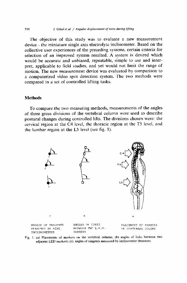
To compare the two measuring methods, measurements of the angles of three gross divisions of the vertebral column were used to describe postural changes during controlled lifts. The divisions chosen were: the cervical region at the C4 level, the thoracic region at the TS level, and the lumbar region at the L5 level (see fig. 1).
c b a
ANGLES OF TANGENTS ANGLES OF LINKS PLACEMENT OF MAFKERS MEASURED BY MINI. BETWEEN TWO L.E.D. ON VERTEBRAL COLC'MN INCLINOMETERS MARKERS
Fig. 1. (a) Placements of markers on the vertebral column; (b) angles of links between two
adjacent LED markers; (c) angles of tangents measured by inclinometer detectors.
I. Gilad et al. / Angular displacement of torso during lifting 551
The specific measuring methods used in this evaluation were: (1) a computerized location method, known as the ‘Selspot 1’ system manu- factured by Selcom, and (2) a new miniature inclinometer system with a detection device, manufactured by Spectron. The detection unit was designed to control the gradient output while being subjected to vibrations along any of the three perpendicular axes. This unit was originally designed for inertial missile guidance systems.
The Selspot 1 measuring system provides estimates of the absolute X-Y locations of markers in a plane. Angles in a single plane are then calculated from the two-dimensional coordinates of two adjacent markers. Changes in curvature of the back segments are measured as the changes in angle between the horizontal and a line formed by joining two adjacent LED markers as shown in fig. la. The new miniature inclinometer system provides a signal which is directly pro- portional to the inclination of the transducer from horizontal. Its frame of reference is relative to the gravity vector. Changes in the curvature of the back segments are measured as changes in the angles between the horizontal and a tangent to the spine at each inclinometer, as shown in fig. lb.
The Selspot I method
The system employed to measure the kinematics of torso curvature was the Selspot 1 computerized spot detection system, with one detec- tion camera. This system has several characteristics not found in other systems for spinal analysis. It includes software to control the entire measurement process from calibration through result presentation. This strongly integrated system produces accurate estimates of the geometric values of spinal kinematics during task performance, with each spot located with +0.5 cm accuracy.
To obtain estimates of the 2-D spatial coordinates of a specific landmark on the human body, a small infrared light emitted diode (IR LED) is attached to a known body segment location. The image of the LED is focused by a lens system onto a semiconductor plate (fig. 2). Signals are obtained from this semiconductor plate which are related to the two-dimensional coordinates of the LED. To be able to measure the coordinates of more than one point, several IR LEDs are time multiplexed. First LED No. 1 emits a pulse of light and its coordinates are registered. Then LED No. 2 emits a pulse and its coordinates are
552 I. Gilad et al. / Angular displacement of torso during lifting
registered, etc. When all the mounted LEDs have been registered, a new measurement cycle starts with LED No. 1. The time required to complete a measurement cycle including a synchronization delay is about 3.3 milliseconds, thus producing a sample frequency of 315 Hz. A more technical description of the Selspot 1 method is found in Waltering and Marsolais (1980).
The Miniature Inclinometer method
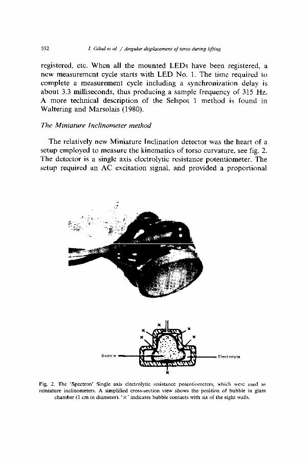
The relatively new Miniature Inclination detector was the heart of a setup employed to measure the kinematics of torso curvature, see fig. 2. The detector is a single axis electrolytic resistance potentiometer. The setup required an AC excitation signal, and provided a proportional
Fig. 2. The ‘Spectron’ Single axis electrolytic resistance potentiometers, which were used as miniature inclinometers. A simplified cross-section view shows the position of bubble in glass
chamber (1 cm in diameter), ‘ X ’ indicates bubble contacts with six of the eight walls.
I. Gilad et al. / Angular displacement of torso during Iifring 553
voltage output as the unit was tilted relative to the vertical gravity vector. This was specifically designed by the manufacturer to measure the gravity vector while being subjected to a variety of motions and vibrations.
The detector is a very small one-piece glass enclosure approximately one centimeter in diameter. The internal platinum contacts and exter- nal terminals are sealed into the glass to prevent electrolyte leakage. The internal geometry is designed so that when the chamber is partially filled with electrolyte, a bubble results which maintains direct surface contact with six of the eight walls. According to the manufacturer, this containment of the bubble gives stability to the performance of the detector as it is rotated. More technical information can be obtained from ‘Spectron’, (595 Old Willets Path, Hanppange, NY 11788, USA).
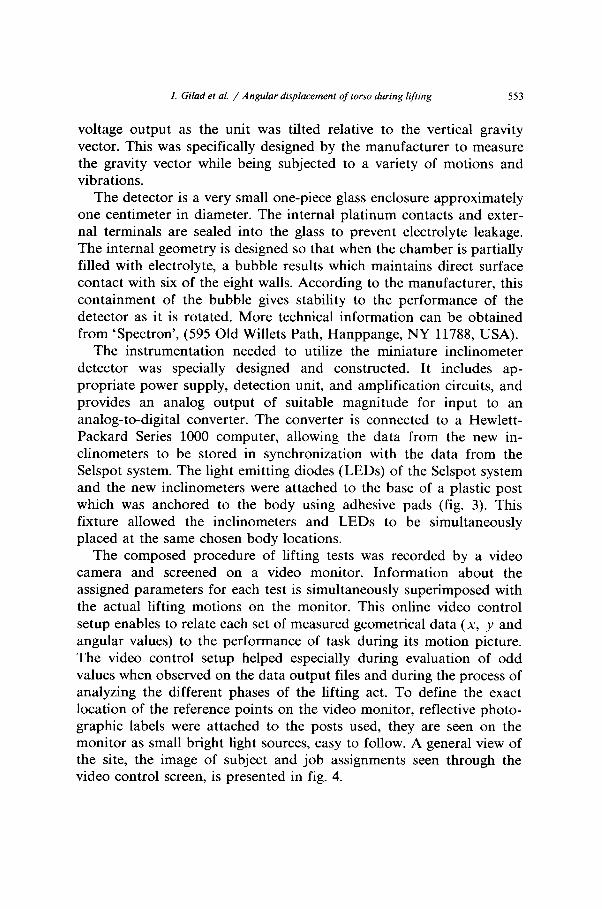
The instrumentation needed to utilize the miniature inclinometer detector was specially designed and constructed. It includes ap- propriate power supply, detection unit, and amplification circuits, and provides an analog output of suitable magnitude for input to an analog-to-digital converter. The converter is connected to a Hewlett- Packard Series 1000 computer, allowing the data from the new in- clinometers to be stored in synchronization with the data from the Selspot system. The light emitting diodes (LEDs) of the Selspot system and the new inclinometers were attached to the base of a plastic post which was anchored to the body using adhesive pads (fig. 3). This fixture allowed the inclinometers and LEDs to be simultaneously placed at the same chosen body locations.
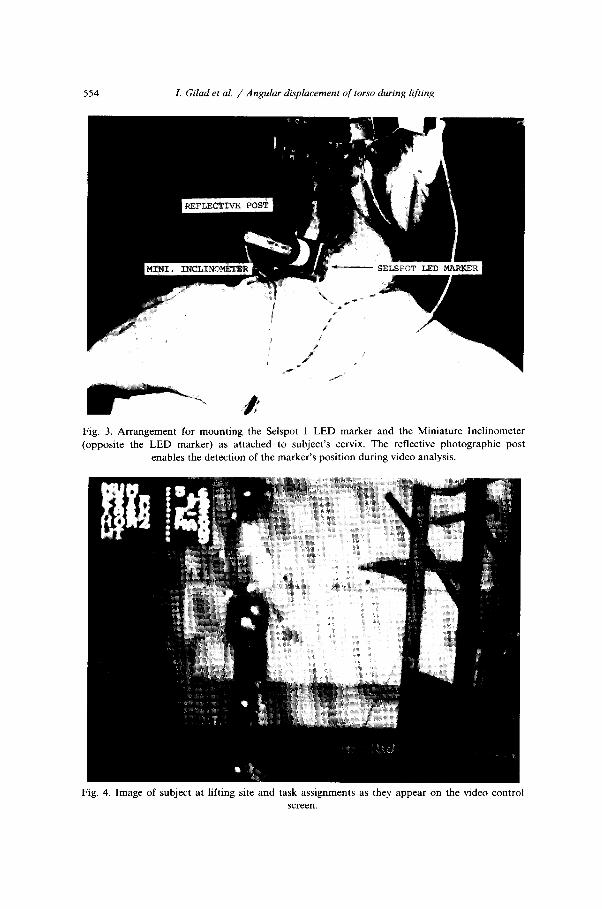
The composed procedure of lifting tests was recorded by a video camera and screened on a video monitor. Information about the assigned parameters for each test is simultaneously superimposed with the actual lifting motions on the monitor. This online video control setup enables to relate each set of measured geometrical data (x, y and angular values) to the performance of task during its motion picture. The video control setup helped especially during evaluation of odd values when observed on the data output files and during the process of analyzing the different phases of the lifting act. To define the exact location of the reference points on the video monitor, reflective photo- graphic labels were attached to the posts used, they are seen on the monitor as small bright light sources, easy to follow. A general view of the site, the image of subject and job assignments seen through the video control screen, is presented in fig. 4.
554 I. Glad et al. / Angular displacement of torso during lifting
\
t‘
/ ,
Fig. 3. Arrangement for mounting the Selspot 1 LED marker and the Miniature Inclinometer
(opposite the LED marker) as attached to subject’s cervix. The reflective photographic post enables the detection of the marker’s position during video analysis.
Fig. 4. Image of subject at lifting site and task assignments as they appear on the video control screen.

I. Gilad et al. / Angular displacement of torso during lifting 555
Fig. 5. Instrumentation setup for the angular displacement of torso during lifting. Block diagrams
present major compotents of the two measuring systems and the video control units.
Fig. 5 illustrates the components of two measuring systems together with the video control setup and the computer. The LED Control Unit (LCU), which is carried by the subject, contains the master clock of the system and performs time multiplexing of the LEDs. It connects the main Selspot control unit through a cable which carries power to the LED control unit and synchronization pulses to a slave clock contained in the main Selspot control unit. The Inclinometer Control Unit (ICL) is also carried by the subject and connects the 3 inclinometers and power supply to the A to D converter. The electrical cables, connec- tions to the LED markers and inclinometers, were attached to the subject’s body in such a way that they would not interfere with his movements.
Experimental design
The comparison of the systems’ abilities to detect torso kinematics accurately was accomplished by having two subjects perform weight lifting tasks of varying magnitudes, from different horizontal locations, to assigned heights, in various lifting postures. A mixed variable design was used for this comparative study, based on the variables described in table 1. The categorical variables assigned were: subject gender, lifting posture, and lifting heights. The random variables were: horizon-

556 I. Gilad et al. / Angular displacement of torso during lifting
Table 1
The variables for systems comparison and lifting tasks.
Variable
Categorical
(1) Sex
(2) Lifting
posture
(3) Lift height
Detailed variable Code & value
Female
Male
Straight back & flex knees
Flexed Back & straight knees
Free, unconstrained
Floor to knuckle
Floor to shoulder
Floor to reach height
Knuckle to shoulder
Knuckle to reach height
Shoulder to reach height
(F) W (SW
WV (FREE)
(F-K)
(F-S) (F-RH)
(K-S) (K-RH)
(S-RH)
Random
(1) Horizontal distance Minimal reach F=16M=15(cm)
Maximal reach F=32M=31(cm)
(2) Weight magnitude relative to ILS test Minimum F & M = 0.6 (kg)
Medium a
Maximum a
a Weight lifting (med. and max.) values as related to subjects by ILS test are listed in table 2.
tal distance and weight magnitudes as they were related to the subjects’ muscular capacity and anthropometry.
Two volunteer subjects, male and female, participated in the study. Their present and past health histories were checked and they were found to be healthy with no medical limitations of the musculoskeletal system. Because of the biomechanics of lifting, the change in curvature of the spine when loaded, is postulated to be greater in women than in men (Tichauer et al. 1973). The subjects were both 21 years of age, the male being 172 cm in height and 67 kg in weight, the female 174 cm and 55 kg.
Three lifting postures were assigned to compare the trunk measuring methods, since it is believed that biomechanical evaluation must con- sider the different geometry produced by each lifting technique: straight back flexed knees, flexed back straight knees, commonly referred to as stooped lifting posture. There is no clear biomechanical rationale for deciding between the two postures for the preferred method over a
I. Gilad et al. / Angular displacement of torso during lifting 557
wide range of lifting conditions (Garg and Herrin 1979), and observa- tions of workers in practical materials handling tasks show that weights are lifted in composed combinations of back and leg flexion. Therefore, a third posture was assigned which will be referred to as the ‘Free’ unconstrained posture, where the subject executes the lifting assign- ments in his/her preferred posture of choice.
Lifting heights and lifting destinations were set relative to the subject’s reach, i.e. floor to knuckle (F-K), floor to shoulder (F-S), floor to reach height (F-RH), knuckle to shoulder (K-S), knuckle to reach height (K-RH) and shoulder to reach height (S-RH) levels. This provided reference heights easily defined and related to each subject’s anthropometry.
Horizontal distance from subject to the origin of the lifted weight is an important factor to the biomechanics of lifting. Therefore, two horizontal reach distances were assigned, measured from the ankle to the center of the object’s mass. The distances are referred to as minimal and maximal reach. The distances varied between the lifting postures and weights to be lifted according to subject’s abilities measured during an isometric lifting strength test.
It was desired that the subjects perform the tasks at their own pace and at a comfortable level of muscular exertion. The minimum weight lifted was constant for all postures and tasks. It was an empty box weighing 0.6 kilograms. The medium and maximum weights, however, were determined relatively to the subject’s maximal isometric strength. This maximum strength was measured using the Isometric Lifting Strength Test ILS Test) as used by Chaffin (1975). The test protocol is well described by Caldwell et al. (1974). Each subject was tested while performing a maximum volitional isometric exertion in a posture requiring the maximum exertion at each task height. Thirty and fifty percent of these maximal isometric values were chosen as the medium and maximum lift loads, respectively, for each posture task. The use of three loads provided the ability to systematically test lifts from each subject. Since the lifts from shoulder to overhead heights are not performed with flexed back, and the lifts from knuckle height apply to minimal reach distances only, the number of lifts was reduced to 87. Table 2 presents the medium and maximum lifting weight values as resulted from the ILS tests.

Tab
le
2
Wei
ght
lift
ing
med
. an
d m
ax.
valu
es
(kg)
fo
r su
bjec
ts
in d
iffe
ren
t li
ftin
g po
stu
res
and
hei
ght
assi
gnm
ents
.
Lif
tin
g L
ifti
ng
Fem
ale
subj
ect
Mal
e su
bjec
t
Pos
ture
h
eigh
ts
Min
imal
re
ach
*
Max
imal
re
ach
M
inim
al
reac
h
Max
imal
re
ach
Q
3
Med
. w
eigh
t M
ax.
wei
ght
Med
. w
eigh
t M
ax.
wei
ght
Med
. w
eigh
t M
ax.
wei
ght
Med
. w
eigh
t M
ax.
wei
ght
n_
C?
SB
F
-K
10
17
4 7
16
SB
F
-S
10
14
4 7
16
SB
F
-RH
10
14
4
I 16
S
B
K-S
13
16
_
_ 26
S
B
K-R
H
13
15
_ _
26
SB
S
-RH
6
10
_ 7
27
27
27
35
35
11
13
13
13
_ _
FB
F
-K
14
23
5 8
20
FB
F
-S
14
15
5 8
20
FB
F
-RH
14
15
5
8 20
FB
K
-S
11
14
_ _
25
FB
K
-RH
11
14
_
_ 25
FB
S
PR
H
- _
_ _
FR
EE
F
-K
13
22
10
17
20
FR
EE
F
-S
13
15
10
14
20
FR
EE
F
-RH
13
15
10
14
20
F
RE
E
K-S
11
14
11
14
23
F
RE
E
K-R
H
11
14
11
14
23
FR
EE
S
-RH
5
10
4 9
I
34
34
34
35
35
34
34
34
33
33
11
17
28
17
28
17
28
14
14
14
_ _
17
28
17
28
6 10
I. Gilad et al. / Angular displacement of torso during lifting
Results
Spinal configuration data were obtained simultaneously from both
559
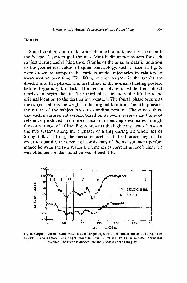
the Selspot 1 system and the new Mini-Inclinometer system for each subject during each lifting task. Graphs of the angular data in addition to the geometrical values of spinal kinesiology, such as seen in fig. 6, were drawn to compare the various angle trajectories in relation to torso motion over time. The lifting motion as seen in the graphs are divided into five phases. The first phase is the normal standing posture before beginning the task. The second phase is while the subject reaches to begin the lift. The third phase includes the lift from the original location to the destination location. The fourth phase occurs as the subject returns the weight to the original location. The fifth phase is the return of the subject back to standing posture. The curves show that each measurement system, based on its own measurement frame of reference, produced a conture of instantaneous angle estimates through the entire range of lifting. Fig. 6 presents the high consistency between the two systems along the 5 phases of lifting during the whole act of Straight Back lifting, the measure level is at the thoracic region. In order to quantify the degree of consistency of the measurement perfor- mance between the two systems, a time series correlation coefficient (r) was obtained for the spinal curves of each lift.
0
12
10
8
i 6
El
4
* 2
0 50 100 150 200 250 300
TIME l/loo sec.
Fig. 6. Selspot 1 versus Inclinometer system’s angle trajectories for female subject at TS region in SB/FK lifting posture. Lift height-floor to knuckle, weigh- 10 kg in minimal horizontal
distance. The graph is divided into the 5 phases of the lifting act.
560 I. Gilad et al. / Angular displacement of torso during lifting
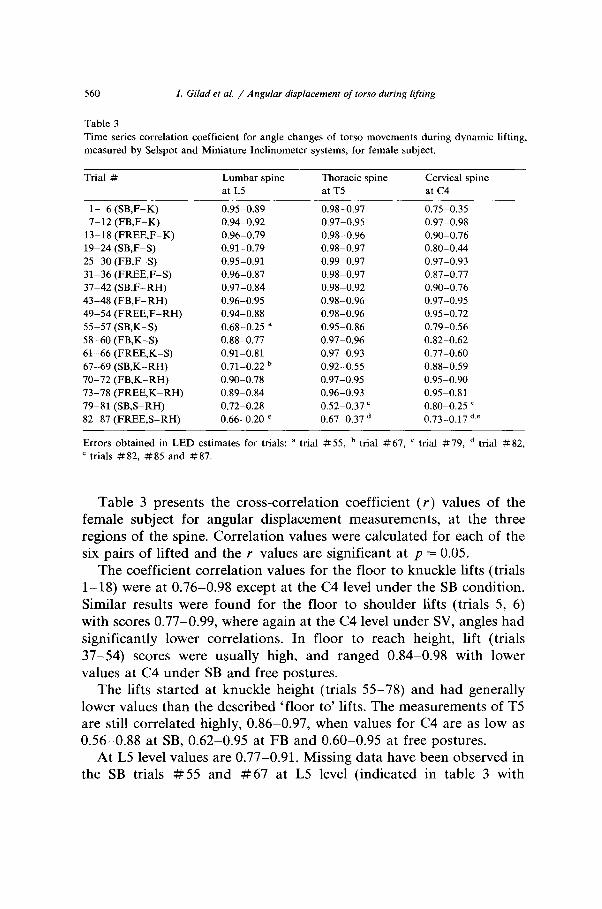
Table 3
Time series correlation coefficient for angle changes of torso movements during dynamic lifting,
measured by Selspot and Miniature Inclinometer systems, for female subject.
Trial #
l- 6 (SB,F-K)
7-12 (FB,F-K)
13-18 (FREE,F-K)
19-24 (SB,F-S)
25-30 (FB,F-S)
31-36 (FREE,F-S)
37-42 (SB,F-RH)
43-48 (FB,F-RH)
49-54 (FREE,F-RH)
55-57 (SB,K-S)
58-60 (FB,K-S)
61-66 (FREE,K-S)
67-69 (SB,K-RH)
70-72 (FB,K-RH)
73-78 (FREE,K-RH)
79-81 (SB,S-RH)
82-87 (FREE,S-RH)
Lumbar spine
at L5
0.95-0.89
0.94-0.92
0.96-0.79
0.91-0.79
0.95-0.91
0.96-0.87
0.97-0.84
0.96-0.95
0.94-0.88
0.68-0.25 a
0.88-0.77
0.91-0.81
0.71-0.22 b
0.90-0.78
0.89-0.84
0.72-0.28
0.66-0.20 e
Thoracic spine
at T5
0.98-0.97
0.97-0.95
0.98-0.96
0.98-0.97
0.99-0.97
0.98-0.97
0.98-0.92
0.98-0.96
0.98-0.96
0.95-0.86
0.97-0.96
0.97-0.93
0.92-0.55
0.97-0.95
0.96-0.93
0.52-0.37 =
0.67-0.37 d
Cervical spine
at c4
0.75-0.35
0.97-0.98
0.90-0.76
0.80-0.44
0.97-0.93
0.87-0.77
0.90-0.76
0.97-0.95
0.95-0.72
0.79-0.56
0.82-0.62
0.77-0.60
0.88-0.59
0.95-0.90
0.95-0.81
0.80-0.25 ’
0.73-0.17 d.e
Errors obtained in LED estimates for trials: a trial #55, b trial #67, ’ trial #79, d trial #82,
e trials #82, #85 and #87.
Table 3 presents the cross-correlation coefficient (r) values of the female subject for angular displacement measurements, at the three regions of the spine. Correlation values were calculated for each of the six pairs of lifted and the r values are significant at p = 0.05.
The coefficient correlation values for the floor to knuckle lifts (trials 1-18) were at 0.76-0.98 except at the C4 level under the SB condition. Similar results were found for the floor to shoulder lifts (trials 5, 6) with scores 0.77-0.99, where again at the C4 level under SV, angles had significantly lower correlations. In floor to reach height, lift (trials 37-54) scores were usually high, and ranged 0.84-0.98 with lower values at C4 under SB and free postures.
The lifts started at knuckle height (trials 55-78) and had generally lower values than the described ‘floor to’ lifts. The measurements of T5 are still correlated highly, 0.86-0.97, when values for C4 are as low as 0.56-0.88 at SB, 0.62-0.95 at FB and 0.60-0.95 at free postures.
At L5 level values are 0.77-0.91. Missing data have been observed in the SB trials # 55 and #67 at L5 level (indicated in table 3 with
I. Gilad et al. / Angular displacement of torso during lifting 561
superscript a and b). In this set of liftings, electrical interference was detected between LEDs and the reception camera was detected which enabled estimation of one of the markers and this affected the mea- sures.
The final data set for liftings which start at shoulder height (trials 79-87) has a few undetected measurements; this is mainly due to electrical interference as mentioned, and the fact that with one signal reception camera, instantaneous out of plane LED signals were not detected. In this set of lifts r’s of negative and low value were calculated (trials #79, # 82, # 85 and # 87). Body movements in the transverse plane were observed when subjects tend to move one foot forward to gain closer distance in maximal horizontal reach with a free posture. Such body movements produce torso and neck twisting mo- tions which enable the detection of LEDs with one camera.
In general, the analysis reveals that the two methods in this set of obtained data show consistent agreement in angle trajectory at the thoracic level, few differences occur at lumbar level, and so at the cervical level. The correlations coefficient tends to be lower when the subject uses a straight back lifting posture, and as the origin of the lift is raised.
The correlation analysis performed on means valued for all subjects’ liftings shows that there is an acceptable positive correlation ( rmean = 0.814) between the two systems. An analysis of variance was performed on systems performance (table 4); this statistical check indicates that the location of the detection devices on the trunk has significant effects on the system’s correlation. The two systems show a highly consistent
Table 4 Analysis of variance for the lifting variables to compare the data obtained by the two measuring systems. Results indicate the significance of each variable to the correlations between the systems.
Variable Number of levels
Sum of square
Mean square
F
test
Location of system detectors on the spinal curve
Posture Lifting height Weight Horizontal distance
3 0.514 0.257 4.009 a 3 1.157 0.578 12.497 a 6 7.427 1.485 39.363 a 3 0.465 0.233 3.618 = 2 0.134 0.134 2.052
a p < 0.05.

562 I. Gilad et al. / Angular displacement of torso during lifting
agreement in angle trajectory over time at the thoracic region (r,,,, = 0.872), but differences occur at the lumbosacral level ( rmea = 0.804) and at the cervical level ( rm_ = 0.765). The correlation values were lower when subjects used a free posture (rmean = 0.779) or a straight back lifting posture (T,,,_ = 0.751) rather than a flex back posture
( rIIl,Il = 0.935). Raising the origin of lift height produced lower correla- tions. The correlation mean ( rm_ = 0.9444) for the floor to knuckle and to shoulder height trials was rather high at the L5 and T5 levels, while the angle estimations at the C4 region had significantly lower correlation values ( rmean = 0.633) under the straight back conditions. In floor to reach height trials, the C4 level correlations increased under the straight back ( rmean = 0.835) but no significant changes were shown at the lumbosacral and thoracic levels. The lifts which started at knuckle height had generally lower values than the previously described floor trials. The measurements at T5 were still highly correlated ( rmean = 0.911) but the values at the L5 (rmean = 0.672) and C4 (Y,,,, = 0.753) levels are lower. A significant reduction of the correlation mean ( rmean
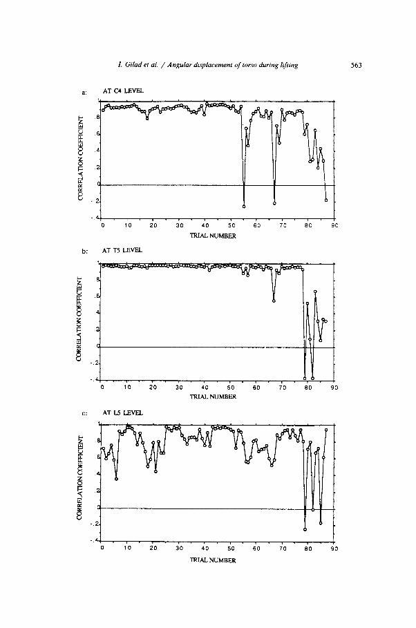
= 0.316) is seen in the straight back trials at the L5 level. The correlations ( rmean = 0.945) at the thoracic level trials were high except for the shoulder lifting origin height trials ( rmean = 0.155) under the straight back and the free conditions. The shoulder lifting origin height trials produced a lower correlation mean ( rmean = 0.333) than the other lifting origin conditions. From observations of the video tapes, the subjects demonstrated instability of trunk movements, especially in heavier loads, at this set of lifts. These instability movements produce r&-reception in the Selspot reading unit which results in misreadings, as seen in table 3 (points (c), (d) and (e)). Relatively higher correlations were shown at the thoracic region than at the lumbosacral and the cervical regions. These correlation effects are visualized in fig. 7, where variation of the r values are graphically presented along the lifting trials.
The system’s performance similarity improved as the weight of lift increased. The differences in the correlation means between the maxi-
mum (rmean = 0.861) and the minimum ( rmean = 0.758) weights were
Fig. 7. Variation of correlation means at the three spinal regions: (a) at C4; (b) at T5; (c) at L5 levels. These graphs represent the correlation coefficient values for a female subject along all
lifting trials.
I. Gilad et al. / Angular displacement of torso during lifting
AT CS LEVEL
2.
a,. I, I. 1. 8, 8. I. 8. r r 0 10 20 30 40 50 60 70 80 90
TRIAL NuhQER
AT TS LEVEL
6
4
2
0
. . 2.
. . r 0 10 20 30 40 50 60 70 80 90
TRIALNUMBER
C: ATLJLEVEL
0 10 20 30 40 50 60 70 80 90
563
lm‘u NUMBER

564 I. Gilad et al. / Angular displacement of torso during lifting
significant (F-test at 5% significance level). The weight levels of lift did not interact with the system location factor, which means that the correlation at the thoracic level were consistently high for all the weight levels.
Discussion
The Selspot 1 system has been considered to offer a sophisticated, online method of obtaining accurate co-ordinate data during a motion despite existing technical imperfections (Atha 1984). The use of an Inclinometer, as reported by Pearcy (1986), shows that the system provides an acceptable accuracy in measuring spinal inclines.
The results mentioned above, however, revealed that the two systems showed different measurement performances according to the change of lifting task conditions. In the course of the present study, reasons for the difference between the two methods emerged:
(1) Difference in system references: The Selspot, which has the capability to estimate body configurations in three-dimensional space by using two cameras or more simultaneously, was configured with only one camera in this experiment. It was, therefore, limited to analysis of movement in one plane (i.e. and sagittal plane). Since this system is limited to measurement in a single plane, overgenerous movement of body segment can cause landmarks to move towards or away from the camera, resulting in measurement error. The inclinome- ter, however, is not constrained in the same manner because the system used in the study was originally designed to measure a two-dimensional body segment motion. This system measures angles relative to the vertical vector. In other words, the Selspot plane of measurement is referenced to camera and landmark positions while the inclinometer plane of measurement is referenced to the vertical vector and may be as sensitive to rotational or twisted motions as the Selspot.
(2) Adjacent body segment motion: System measurement of a motion can be affected by movement of adjacent body segments. The position- ing of landmarks on the skin surface may be a source of measurement errors. The reference centers marking joint centers are perceived to have moved whenever a motion of adjacent body segment produces the skin movement or rotation of the measured body segment. Further-
I. Gilad et al. / Angular displacement of torso during lifting 565
more, the difference of measurement reference frames between the two systems can produce synergetic effects on the measurement errors when it is combined with adjacent body segment motion. For example, head movement in three-dimensional space caused a lower correlation be- tween the Selspot and the Inclinometer system’s performance at the cervical region rather than the thoracic and the lumbosacral levels because the Selspot system measured inclines of cervical spine using a linear combination of coordinate data points obtained from the land- marks locating on the cervical level and the eye level on the head. Adjacent body motion may not have as great an effect on the Inclino- meter system as on the Selspot but excessive body movement can generate measurement error because the system is not reliable when angular motion is within + 60 degrees.
(3) Difference in initial conditioning: Though care was taken to calibrate both systems at the start of the experiment to reduce optical distortion, LED signal errors, and minimize the alignment error, calibration differences may still cause disagreement in the measurement system performances.
Agreement in system performance for measuring torso configuration tended to decline as the experiment progressed. It may be that there were residual carryover effects from task to task, such as fatigue and a tendency to prefer free posture rather than straight back or flex back lifting positions to gain additional lifting momentum regardless of a given condition. Also, as the experiment progressed, unexpected mo- tions in the frontal and/or transverse planes could occur while move- ment dynamics increased. Further comparisons will be necessary to determine the exact cause of the decline in the correlation between the two systems during the experimental sessions.
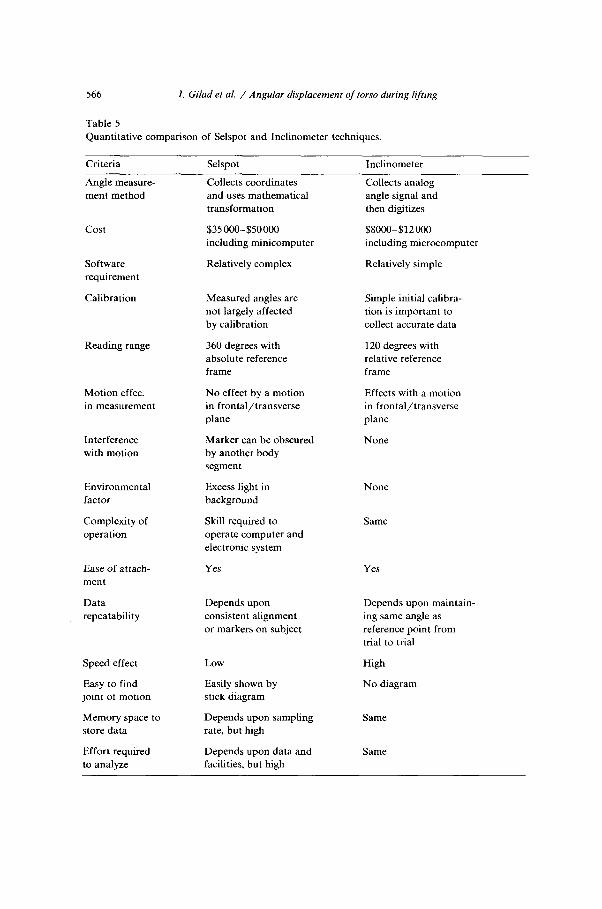
Table 5 presents a qualitative comparison of the characteristics of the two measuring methods with regard to the criteria mentioned earlier.
The pros and cons of the Selspot measuring system used in this experiment are quite similar to the critique provided by Chao (1978). The advantages of Selspot which are derived from the study are as follows:
(a) The method estimates a torso inclination in an absolute reference frame without reading limitation of range, and thus it is easily used in biomechanical studies.
566
Table 5
I. Gilad et al. / Angular displacement of torso durmg lifting
Quantitative comparison of Selspot and Inclinometer techniques.
Criteria Selspot inclinometer
Angle measure-
ment method
cost
Software
requirement
Calibration
Reading range
Motion effec.
in measurement
Interference
with motion
Environmental
factor
Complexity of
operation
Ease of attach-
ment
Data
repeatability
Speed effect Low
Easy to find joint of motion
Easily shown by
stick diagram
Memory space to
store data
Depends upon sampling
rate, but high
Effort required
to analyze
Depends upon data and facilities, but high
Collects coordinates and uses mathematical
transformation
$35 OOO-$50000
including minicomputer
Relatively complex
Measured angles are
not largely affected
by calibration
360 degrees with
absolute reference
frame
No effect by a motion
in frontal/transverse
plane
Marker can be obscured by another body
segment
Excess light in
background
Skill required to
operate computer and
electronic system
Yes
Depends upon
consistent alignment
or markers on subject
Collects analog
angle signal and
then digitizes
$8000-$12000
including microcomputer
Relatively simple
Simple initial calibra-
tion is important to
collect accurate data
120 degrees with
relative reference
frame
Effects with a motion
in frontal/transverse
plane
None
None
Same
Yes
Depends upon maintain-
ing same angle as
reference point from
trial to trial
High
No diagram
Same

I. Gilad et al. / Angular displacement of torso during lifting 561
(b) Joint centers can be accurately located by connected two-dimen- sional coordinates of two reference LEDs placed on each segment. A stick diagram of a human motion can also be produced.
(c) The method is not sensitive to acceleration and deceleration effects which can cause overestimates or underestimates in measurement for the beginning and ending points of a motion.
(d) The method can be easily performed with integrated software calibration which reduces the time and effort for setup.
(e) The LEDs in the system can be accurately located, which is critical to measurement accuracy.
(f) Effect of a motion in frontal and/or transverse planes can be kept minimal for measurement accuracy of two-dimensional coordi- nates. Therefore the system can be applied to many different types of motions without loss of measurement accuracy.
Disadvantages of the Selspot method are:
(a) Complex and expensive equipment and software are required to obtain data accurately and also to manipulate fast sampling rate.
(b) A large amount of data from a high sampling rate needs system interface between the Selspot method and a digital computer.
(c) A fair amount of technical expertise is required to manipulate the computer and electronic systems.
(d) Motions of other body segments can interfere by covering the light emission from the diode. This may lead to the misreadings in measurement during the data capturing process.
(e) The system is sensitive to infra-red light so that it is required to remove any kind of light sources generating infra-red hum in the background
(f) Consistent alignment of LED locations is required to maintain accuracy and repeatability of data.
The use of the Mini-Inclinometer method also has advantages that should be recognized. Advantages of the Mini-Inclinometer method are :
(a) The direct angle measurement method reduces the equipment and software requirements.
(b) Equipment is relatively inexpensive and easy to use.
568 I. Gilad et al. / Angular displacement of torso during lifting
(c) The data acquisition process is independent of other body segment motion at every reference point.
(d) The measurement function is not obscured by environmental fac- tors such as illumination.
(e) Error from the optical distortion does not exist in the measurement.
Disadvantages of the Mini-Inclinometer method are:
(4
(b)
cc>
(4
Relative reference frame in angle measurement requires careful initial calibration. The device must be located at exactly the same place and maintain the same alignment at every reference point for data repeatability. It is difficult to visualize the specific linkage behavior because the system does not provide a visual ‘stick’ diagram of the entire motion. The angle measurement method from the bubble movement in sagittal plane can be relatively affected from a motion in frontal and/or transverse plane, which can reduce system measurement accuracy. The system is sensitive to acceleration and deceleration effects. Accelerations of greater than about 3-4 Hz may cause misreadings in the recordings.
Conclusions
The use of the Mini-Inclinometer system, which is an online, two-di- mensional continuous angular detection technique for spinal motion analysis, has been shown to provide an acceptable measurement perfor- mance similarity ( rmean = 0.814) for the whole set of lifting trials. It has been compared to the Selspot 1 method which is a commonly found motion analyzer in a laboratory experienced in lifting investigation. The Mini-Inclinometer method as used in this study has performed well for a wide range of torso flexion and extension movements.
References
Anderson, C.K. and D.B. Chaffin, 1984. A biomechanical evaluation of five lifting techniques. Presented at the International Conference of Occupational Ergonomics.

I. Gilad et al. / Angular displacement of torso during lifting 569
Atha, J., 1984. Current techniques for measuring motions. Applied Ergonomics 15, 245-257. Ayoub, M.M. and M.M. El-Bassoussi, 1978. ‘Dynamic biomechanical model for sagittal plane
lifting activities’. In: G.G. Drury (ed.), Safety in manual materials handling. DHEW (NIOSH) Publ. no. 78-185, 88-95.
Caldwell, L.S., D.B. Chaffin, F.N. Dukes-Dobos, K.H.E. Kroemer, L.L. Lauback, S.H. Snook and D.E. Wasserman, 1974. A proposed standard procedure for static muscle strength testing. Journal of the American Industrial Hygiene Association 35, 201-212.
Chaffin, D.B., 1975. Ergonomic guide for the assessment of human static strength. Journal of the American Industrial Hygiene Association 35, 505-510.
Chaffin, D.B. and G. Anderson, 1984. Occupational biomechanics. New York: Wiley. Chaffin, D.B. and W.H. Baker, 1970. A biomechanical model for analysis of symmetric sagittal
plane lifting. ABE Transactions 2(l). Chao, E.Y., 1978. ‘Experimental methods for biomechanical measurements of the joint kine-
matics’. In: B.N. Feinberg and D.G. Fleming (eds.), CRC handbook for engineering in medicine and biology, Vol. 1. Cleveland, OH: CRC Press Inc. pp. 385-411.
Davis, P.R., J.D.G. Troup and J.A. Burnard, 1965. Movements of the thoracic and lumbar spine when lifting: A chrono-cyclophotographic study. Journal of Anatomy 99, 13-26.
Drury, C.G. (ed.), 1978. Safety in manual materials handling. DHEW, (NIOSH) Publ. no. 78-185. Garg, A. and G.D. Herrin, 1979. Stoop of squat: A biomechanical and metabolic evaluation. AIIE
Transactions 11, 293-302. Herrin, G.D., D.B. Chaffin and R.S. Mach, 1974. Criteria for research on the hazards of manual
materials handling. NIOSH Contract Report, CDC 99-74-118. National Safety Council Accident Facts, 1984. NIOSH (National Inst. for Occupational Safety and Health), 1981. Work practices guide for
manual lifting. NIOSH Tech. Report Pub. No. 81-122, U.S. Dept. of Health and Human Services.
Nordin, M., R. Ortengren and G.B.J. Anderson, 1984. Measurement of trunk movements during work. Spine 9, 465-469.
Otun, E.O. and J.A.D. Anderson, 1988. An inclinometric method for continuous measurement of sagittal movement of the lumbar spine. Ergonomics 31, 303-315.
Pearcy, M., 1986. Measurement of back and spinal mobility. Clinical Biomechanics 1, 44-51. Reynolds, P.M.G., 1975. Measurement of spinal mobility: A comparison of three models.
Rheumatology and Rehabilitation 14, 180-185. Roebuck, J.A., 1968. A system of notation and measurement for space suite mobility evaluation.
Human Factors 101, 79-94. Snook, S.H., 1978. The design of manual handling tasks. Ergonomics 21, 963-985. Tichauer, E.R., 1978. The biomechanical basis of ergonomics. New York: Wiley Interscience. Tichauer, E.R., M. Miller and I.M. Nathan, 1973. Lordosimetry: A new technique for the
measurement of postural response to material handling. American Industrial Hygiene Associ- ation Journal 1, 1-12.
Woltering, J.P. and E.B. Marsolais, 1980. Optoelectric (Selspot) gait measurement in two and three dimensional space-A preliminary report. Bulletin of Prosthetic Research BPR-10 17(2), 45-52.


![Torque, Angular momentum & equilibriumDec 05, 2016 · [TORQUE, ANGULAR MOMENTUM & EQUILIBRIUM] CHAPTER NO. 5 ò ó , Rotational Kinematics i.e. Angular Displacement, Velocity, Acceleration](https://img.pdfslide.us/doc/110x75/5e6f6c81ea7ec22c07242904/torque-angular-momentum-equilibrium-dec-05-2016-torque-angular-momentum.jpg)