Embed Size (px)
Citation preview

ANGLEGRINDER KIT125mm (5”) 1010WORIGINAL INSTRUCTIONSSPECIFICATIONSMotor: 1010WNo Load Speed: 12,000/minCutting Diameter: 125mm (5”)Spindle: M14Weight: 2.2kg
AGM-5005U
WHAT’S IN THE BOX
Angle Grinder
Inner & Outer Flange
Hex Key
Side Handle
ozito-diy.co.uk
Pin Spanner
5x Grinding Discs & Metal Cutting Disc
Grinding Guard & Cutting Guard
Danger: Do not exceed the max. safe speed
125m
m (5”) Metal Grinding D
isc
Max 12,200 R
PM
Danger: Do not exceed the max. safe speed
125m
m (5”) Metal Grinding D
isc
Max 12,200 R
PM
Danger: Do not exceed the max. safe speed
125m
m (5”) Metal Grinding D
isc
Max 12,200 R
PM
Danger: Do not exceed the max. safe speed
125m
m (5”) Metal Grinding D
isc
Max 12,200 R
PM
Danger: Do not exceed the max. safe speed
125m
m (5”) Metal Grinding D
isc
Max 12,200 R
PM
Danger: Do not exceed the max. safe speed
125m
m (5”) Metal Cuttin
g D
isc
Max 12,000 R
PM
WARRANTY
OZITO UK Unit 9 Stadium Court, Wirral International Business Park, Plantation Road, Bromborough, Wirral, CH62 3QG 0716
All of our products undergo strict quality checks to ensure that they reach you in perfect condition. In the unlikely event that your device develops a fault, please contact our service department at the address shown on this guarantee card. You can also contact us by telephone using the customer service number shown. Please note the following terms under which guarantee claims can be made:
1. These warranty terms regulate additional warranty services, which themanufacturer mentioned below promises to buyers of its new productsin addition to their statutory guarantee claims are not affected by thisguarantee. Our guarantee is free of charge to you.
2. The warranty services only covers defects due to material ormanufacturing faults on a product which you have bought from themanufacturer mentioned below are limited to either the rectification of saiddefects on the product or the replacement of the product, whichever weprefer.Please note that our devices are not designed for use in commercial, tradeor professional applications. A guarantee contract will not be created if thedevice has been used by commercial, trade or industrial business or hasbeen exposed to similar stresses during the guarantee period.
3. The following are not covered by our guarantee:- Damage to the device caused by a failure to follow the assemblyinstructions or due to incorrect installation, a failure to follow the operatinginstructions (for example connecting it to an incorrect mains voltage orcurrent type) or a failure to follow the maintenance and safety instructionsor by exposing the device to abnormal environmental conditions or by lackof care and maintenance.- Damage to the device caused by abuse or incorrect use (for exampleoverloading the device or the use or unapproved tools or accessories),ingress of foreign bodies into the device (such as sand, stones or dust,transport damage), the use of force or damage caused by external forces(for example by dropping it).
- Damage to the device or parts of the device caused by normal or naturalwear or tear or by normal use of the device.
4. Your Product is guaranteed for a period of 36 months from the originaldate of purchase and is intended for DIY (Do It Yourself) use only. LithiumIon batteries and chargers are covered by a 12 month warranty. Warrantyexcludes consumable parts. Guarantee claims should be submittedbefore the end of the guarantee period within two weeks of the defectbeing noticed. No guarantee claims will be accepted after the end of theguarantee period. The original guarantee period remains applicable to thedevice even if repairs are carried out or parts are replaced. In such cases,the work performed or parts fitted will not result in an extension of theguarantee period, and no new guarantee will become active for the workperformed or parts fitted. This also applies if an on-site service is used.
IN ORDER TO MAKE A CLAIM UNDER THIS WARRANTY YOU MUST RETURN THE PRODUCT TO THE PLACE OF PURCHASE WITH YOUR REGISTER RECEIPT.
Please refer to the restrictions of this warranty concerning wearing parts, consumables and missing parts as set out in the service information in these operating instructions.
CUSTOMER SERVICE HELPLINE GB: 0151 294 4488 IRL: 1850 882711 Ozito-diy.co.uk
ONLINE MANUALScan this QR Code with your mobile device to take you to the online manual.
Danger: Do not exceed the max. safe speed
125m
m (5”) Metal Cuttin
g D
isc
Max 12,000 R
PM
Danger: Do not exceed the max. safe speed
125m
m (5”) Metal Grinding D
isc
Max 12,200 R
PM
1. Spindle Lock Button
2. Grinding Guard
3. Side Handle
4. Safety Lock Off Switch
5. Trigger Switch
ANGLE GRINDER
KNOW YOUR PRODUCT
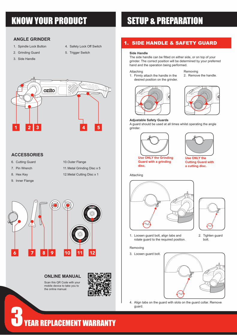
1. SIDE HANDLE & SAFETY GUARD
6. Cutting Guard
7. Pin Wrench
8. Hex Key
9. Inner Flange
10.Outer Flange
11. Metal Grinding Disc x 5
12. Metal Cutting Disc x 1
ACCESSORIES
SETUP & PREPARATION
Adjustable Safety Guards A guard should be used at all times whilst operating the angle grinder.
Use ONLY the Grinding Guard with a grinding disc.
Use ONLY the Cutting Guard with a cutting disc.
Removing2. Remove the handle.
Side HandleThe side handle can be fitted on either side, or on top of yourgrinder. The correct position will be determined by your preferredhand and the operation being performed.
Attaching 1. Firmly attach the handle in the
desired position on the grinder.
Attaching
Removing
3. Loosen guard bolt.
1. Loosen guard bolt, align tabs androtate guard to the required position.
2. Tighten guard bolt.
4. Align tabs on the guard with slots on the guard collar. Removeguard.
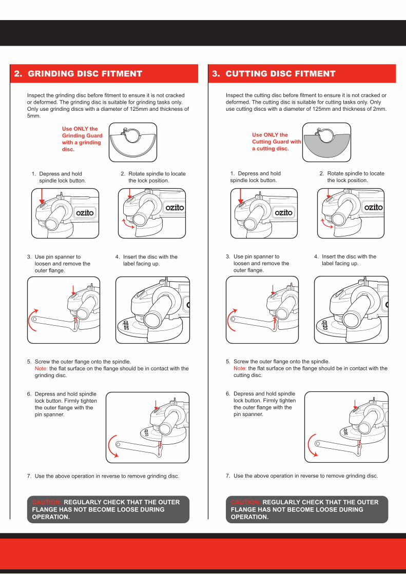
1. Depress and holdspindle lock button.
5. Screw the outer flange onto the spindle.Note: the flat surface on the flange should be in contact with thecutting disc.
2. GRINDING DISC FITMENT
2. Rotate spindle to locatethe lock position.
Inspect the grinding disc before fitment to ensure it is not cracked or deformed. The grinding disc is suitable for grinding tasks only. Only use grinding discs with a diameter of 125mm and thickness of 5mm.
3. CUTTING DISC FITMENT
Inspect the cutting disc before fitment to ensure it is not cracked or deformed. The cutting disc is suitable for cutting tasks only. Only use cutting discs with a diameter of 125mm and thickness of 2mm.
7. Use the above operation in reverse to remove grinding disc.
6. Depress and hold spindlelock button. Firmly tightenthe outer flange with thepin spanner.
3. Use pin spanner toloosen and remove theouter flange.
4. Insert the disc with thelabel facing up.
5. Screw the outer flange onto the spindle.Note: the flat surface on the flange should be in contact with thegrinding disc.
CAUTION: REGULARLY CHECK THAT THE OUTER FLANGE HAS NOT BECOME LOOSE DURING OPERATION.
CAUTION: REGULARLY CHECK THAT THE OUTER FLANGE HAS NOT BECOME LOOSE DURING OPERATION.
1. Depress and holdspindle lock button.
2. Rotate spindle to locatethe lock position.
7. Use the above operation in reverse to remove grinding disc.
6. Depress and hold spindlelock button. Firmly tightenthe outer flange with thepin spanner.
3. Use pin spanner toloosen and remove theouter flange.
4. Insert the disc with thelabel facing up.
Use ONLY the Grinding Guard with a grinding disc.
Use ONLY the Cutting Guard with a cutting disc.
AGM-5005U
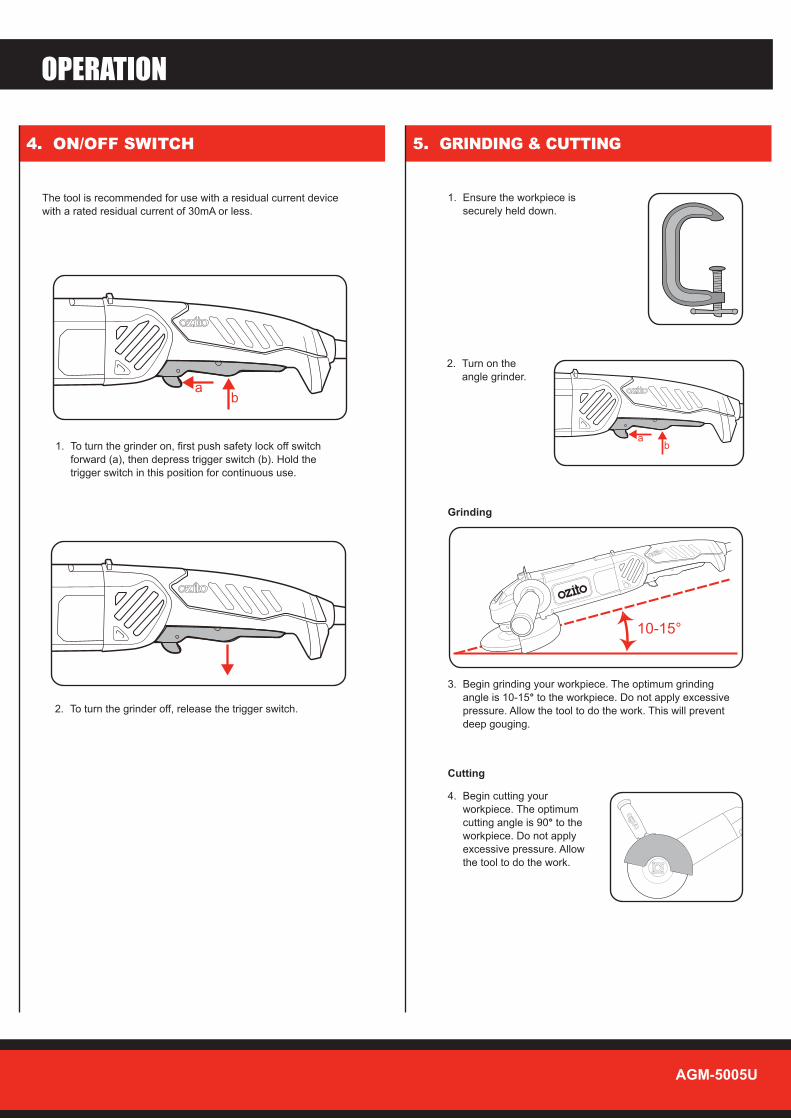
4. ON/OFF SWITCH 5. GRINDING & CUTTING
1. Ensure the workpiece issecurely held down.
2. Turn on theangle grinder.
ab
10-15°
ab
OPERATION
The tool is recommended for use with a residual current device with a rated residual current of 30mA or less.
3. Begin grinding your workpiece. The optimum grindingangle is 10-15° to the workpiece. Do not apply excessivepressure. Allow the tool to do the work. This will preventdeep gouging.
1. To turn the grinder on, first push safety lock off switchforward (a), then depress trigger switch (b). Hold thetrigger switch in this position for continuous use.
2. To turn the grinder off, release the trigger switch.
4. Begin cutting yourworkpiece. The optimumcutting angle is 90° to theworkpiece. Do not applyexcessive pressure. Allow the tool to do the work.
Grinding
Cutting
MAINTENANCE
DESCRIPTION OF SYMBOLS
TROUBLESHOOTING• Keep the ventilation vents of the angle grinder clean at all times, if possible,
prevent foreign matter from entering the vents.• The grease in the gearbox will require replacement / replenishment after
extensive use of the grinder. Please see a qualified electrical repairer to provide this service.
• After each use, blow air through the angle grinder housing to ensure it is free from all dust particles which may build up. Build up of dust particles may cause the angle grinder to overheat and fail.
• If the enclosure of the angle grinder requires cleaning, do not use solvents but a moist soft cloth only. Never let any liquid get inside the angle grinder; never immerse any part of the angle grinder into a liquid.
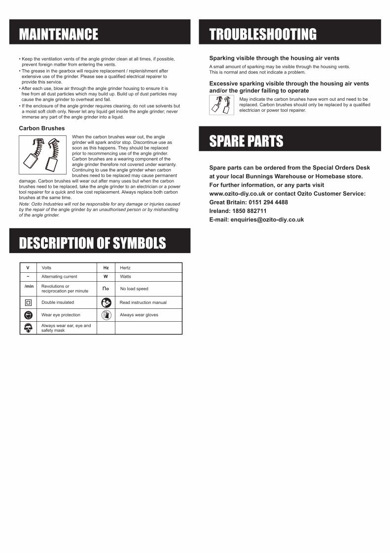
Carbon BrushesWhen the carbon brushes wear out, the angle grinder will spark and/or stop. Discontinue use as soon as this happens. They should be replaced prior to recommencing use of the angle grinder. Carbon brushes are a wearing component of the angle grinder therefore not covered under warranty. Continuing to use the angle grinder when carbon brushes need to be replaced may cause permanent
damage. Carbon brushes will wear out after many uses but when the carbon brushes need to be replaced, take the angle grinder to an electrician or a power tool repairer for a quick and low cost replacement. Always replace both carbon brushes at the same time.Note: Ozito Industries will not be responsible for any damage or injuries caused by the repair of the angle grinder by an unauthorised person or by mishandling of the angle grinder.
Sparking visible through the housing air ventsA small amount of sparking may be visible through the housing vents. This is normal and does not indicate a problem.
Excessive sparking visible through the housing air vents and/or the grinder failing to operate
May indicate the carbon brushes have worn out and need to be replaced. Carbon brushes should only be replaced by a qualified electrician or power tool repairer.
SPARE PARTS
V Volts Hz Hertz
~ Alternating current W Watts
/min Revolutions or reciprocation per minute
Double insulated Read instruction manual
Wear eye protection
Always wear ear, eye andsafety mask
no No load speed
Always wear gloves
Spare parts can be ordered from the Special Orders Desk at your local Bunnings Warehouse or Homebase store. For further information, or any parts visit www.ozito-diy.co.uk or contact Ozito Customer Service: Great Britain: 0151 294 4488Ireland: 1850 882711E-mail: [email protected]
ANGLE GRINDER SAFETY INSTRUCTIONS
Before you connect the equipment to the mains supply make sure that the data on the rating plate are identical to the mains data.
This tool is double insulated therefore no earth wire is required.
If the supply cord is damaged, it must be replaced by an electrician or a power tool repairer in order to avoid a hazard.
Note: Double insulation does not take the place of normal safety precautions when operating this tool. The insulation system is for added protection against injury resulting from a possible electrical insulation failure within the tool.Using an Extension LeadAlways use an approved extension lead suitable for the power input of this tool. Before use, inspect the extension lead for signs of damage, wear and ageing. Replace the extension lead if damaged or defective.When using an extension lead on a reel, always unwind the lead completely. Use of an extension lead not suitable for the power input of the tool or which is damaged or defective may result in a risk of fire and electric shock.
WARNING! Read all safety warnings and all instructions. Failure to follow the warnings and instructions may result in electric shock, fire and/or serious injury. Save all warnings and instructions for future reference. The term “power tool” in the warnings refers to your mains-operated (corded) power tool or battery-operated (cordless) power tool.1. Work area safety a. Keep work area clean and well lit. Cluttered or dark areas invite accidents. b. �Do�not�operate�power�tools�in�explosive�atmospheres,�such�as�in�the�presence�of�flammable�liquids,�
gases or dust. Power tools create sparks which may ignite the dust or fumes.
c. Keep children and bystanders away while operating a power tool. Distractions can cause you to lose control.
2. Electrical safety a. Power tool plugs must match the outlet. Never modify the plug in any way.
Do not use any adapter plugs with earthed (grounded) power tools. Unmodified plugs and matching outlets will reduce risk of electric shock.
b. Avoid body contact with earthed or grounded surfaces, such as pipes, radiators, ranges and refrigerators. There is an increased risk of electric shock if your body is earthed or grounded.
c. Do not expose power tools to rain or wet conditions. Water entering a power tool will increase the risk of electric shock.
d. Do not abuse the cord. Never use the cord for carrying, pulling or unplugging the power tool. Keep cord away from heat, oil, sharp edges or moving parts. Damaged or entangled cords increase the risk of electric shock.
e. When operating a power tool outdoors, use an extension cord suitable for outdoor use. Use of a cord suitable for outdoor use reduces the risk of electric shock.
f. If operating a power tool in a damp location is unavoidable, use a residual current device (RCD) protected supply. Use of an RCD reduces the risk of electric shock.
3. Personal safety a. Stay alert, watch what you are doing and use common sense when operating a power tool. Do not
use�a�power�tool�while�you�are�tired�or�under�the�influence�of�drugs,�alcohol�or�medication. A moment of inattention while operating power tools may result in serious personal injury.
b. Use personal protective equipment. Always wear eye protection. Protective equipment such as dust mask, non-skid safety shoes, hard hat, or hearing protection used for appropriate conditions will reduce personal injuries.
c. Prevent unintentional starting. Ensure the switch is in the off-position before connecting to power source and/or battery pack, picking up or carrying the tool. Carrying power tools with your finger on the
switch or energising power tools that have the switch on invites accidents. d. Remove any adjusting key or wrench before turning the power tool on.
A wrench or a key left attached to a rotating part of the power tool may result in personal injury.
e. Do not overreach. Keep proper footing and balance at all times. This enables better control of the power tool in unexpected situations.
f. Dress properly. Do not wear loose clothing or jewellery. Keep your hair, clothing and gloves away from moving parts. Loose clothes, jewellery or long hair can be caught in moving parts.
g. If devices are provided for the connection of dust extraction and collection facilities, ensure these are connected and properly used. Use of dust collection can reduce dust-related hazards.
4. Power tool use and care a. Do not force the power tool. Use the correct power tool for your application. The correct power tool will
do the job better and safer at the rate for which it was designed. b. Do not use the power tool if the switch does not turn it on and off. Any power tool that cannot be
controlled with the switch is dangerous and must be repaired. c. Disconnect the plug from the power source and/or the battery pack from the power tool before
making any adjustments, changing accessories, or storing power tools. Such preventive safety measures reduce the risk of starting the power tool accidentally.
d. Store idle power tools out of the reach of children and do not allow persons unfamiliar with the power tool or these instructions to operate the power tool. Power tools are dangerous in the hands of untrained users.
e. Maintain power tools. Check for misalignment or binding of moving parts, breakage of parts and any other condition that may affect the power tool’s operation. If damaged, have the power tool repaired before use. Many accidents are caused by poorly maintained power tools.
f. Keep cutting tools sharp and clean. Properly maintained cutting tools with sharp cutting edges are less likely to bind and are easier to control.
g. Use the power tool, accessories and tool bits etc. in accordance with these instructions, taking into account the working conditions and the work to be performed. Use of the power tool for operations different from those intended could result in a hazardous situation.
5. Service a. �Have�your�power�tool�serviced�by�a�qualified�repair�person�using�only�identical�replacement�parts.�
This will ensure that the safety of the power tool is maintained.
GENERAL POWER TOOL SAFETY WARNINGS
ELECTRICAL SAFETY
WARNING! Safety Warnings common for Grinding, Sanding, Wire brushing, Polishing or Abrasive Cutting-Off Operations:a) This power tool is intended to function as a grinder, or cut-off tool. Read all safety warnings, instructions, illustrations and specifications provided with this power tool. Failure to follow all instructions listed below may result in electric shock, fire and/or serious injury.b) Operations such as sanding, polisher or wire brushing are not recommended to be performed with this power tool. Operations for which the power tool was not designed may create a hazard and cause personal injury.c) Do not use accessories which are not specifically designed and recommended by the tool manufacturer. Just because the accessory can be attached to your power tool, it does not assure safe operation.d) The rated speed of the accessory must be at least equal to the maximum speed marked on the power tool. Accessories running faster than their rated speed can break and fly apart.e) The outside diameter and the thickness of your accessory must be within the capacity rating of your power tool. Incorrectly sized accessories cannot be adequately guarded or controlled.f) The arbour size of wheels, flanges, backing pads or any other accessory must properly fit the spindle of the power tool. Accessories with arbour holes that do not match the mounting hardware of the power tool will run out of balance, vibrate excessively and may cause loss of control.g) Do not use a damaged accessory. Before each use inspect the accessory such as abrasive wheels for chips and cracks, backing pad for cracks, tear or excess wear, wire brush for loose or cracked wires. If power tool or accessory is dropped, inspect for damage or install an undamaged accessory. After inspecting and installing an accessory, position yourself and bystanders away from the plane of the rotating accessory and run the power tool at maximum no-load speed for one minute. Damaged accessories will normally break apart during this test time.h) Wear personal protective equipment. Depending on application, use faces shield, safety goggles or safety glasses. As appropriate, wear dust mask, hearing protectors, gloves and workshop apron capable of stopping small abrasive or workpiece fragments. The eye protection must be capable of stopping flying debris generated by various operations. The dust mask or respirator must be capable of filtrating particles generated by your operation. Prolonged exposure to high intensity noise may cause hearing loss.i) Keep bystanders a safe distance away from work area. Anyone entering the work area must wear personal protective equipment. Fragments of workpiece or of a broken accessory may fly away and cause injury beyond immediate area of operation.j) Hold power tool by insulated gripping surfaces only, when performing an operation where the cutting accessory may contact hidden wiring or its own cord. Cutting accessory contacting a “live” wire may make exposed metal parts of the power tool “live” and shock the operator.k) Position the cord clear of the spinning accessory. If you lose control, the cord may be cut or snagged and your hand or arm may be pulled into the spinning accessory.l) Never lay the power tool down until the accessory has come to a complete stop. The spinning accessory may grab the surface and pull the power tool out of your control.m) Do not run the power tool while carrying it at your side. Accidental contact with the spinning accessory could snag your clothing, pulling the accessory into your body.n) Regularly clean the power tool’s air vents. The motor’s fan will draw the dust inside the housing and excessive accumulation of powdered metal may cause electrical hazards.o) Do not operate the power tool near flammable materials. Sparks could ignite these materials.p) Do not use accessories that require liquid coolants. Using water or other liquid coolants may result in electrocution or shock.Kickback and Related WarningsKickback is a sudden reaction to a pinched or snagged rotating wheel, backing pad, brush or any other accessory. Pinching or snagging causes rapid stalling of the rotating accessory which in turn causes the uncontrolled power tool to be forced in the direction opposite of the accessory’s rotation at the point of the binding.For example, if an abrasive wheel is snagged or pinched by the workpiece, the edge of the wheel that is entering into the pinch point can dig into the surface of the material causing the wheel to climb out or kick out. The wheel may either jump toward or away from the operator, depending on direction of the wheel’s movement at the point of pinching. Abrasive wheels may also break under these conditions.Kickback is the result of power tool misuse and/or incorrect operating procedures or conditions and can be avoided by taking proper precautions as given below.a) Maintain a firm grip on the power tool and position your body and arm to allow you to resist kickback forces. Always use auxiliary handle, if provided, for maximum control over kickback or torque reaction during start-up. The operator can control torque reactions or kickback forces, if proper precautions are taken.b) Never place your hand near the rotating accessory. Accessory may kickback over your hand.
c) Do not position your body in the area where power tool will move if kickback occurs. Kickback will propel the tool in direction opposite to the wheel’s movement at the point of snagging.d) Use special care when working corners, sharp edges etc. Avoid bouncing and snagging the accessory. Corners, sharp edges or bouncing have a tendency to snag the rotating accessory and cause loss of control or kickback.e) Do not attach a saw chain woodcarving blade or toothed saw blade. Such blades create frequent kickback and loss of control.Additional safety instructions for grinding and cutting-off operationsSafety Warnings Specific for Grinding and Abrasive Cutting-Off Operations:a) Use only wheel types that are recommended for your power tool and the specific guard designed for the selected wheel. Wheels for which the power tool was not designed cannot be adequately guarded and are unsafe.b) The guard must be securely attached to the power tool and positioned for maximum safety, so the least amount of wheel is exposed towards the operator. The guard helps to protect operator from broken wheel fragments and accidental contact with wheel.NOTE: The above warning may be omitted for die grinders and grinders or cut-off grinders with rated capacity of less than 55mm.c) Wheels must be used only for recommended applications. For example: do not grind with the side of cut-off wheel. Abrasive cut-off wheels are intended for peripheral grinding, side forces applied to these wheels may cause them to shatter.d) Always use undamaged wheel flanges that are of correct size and shape for your selected wheel. Proper wheel flanges support the wheel thus reducing the possibility of wheel breakage. Flanges for cut-off wheels may be different from grinding wheel flanges.e) Do not use worn down wheels from larger power tools. Wheel intended for larger power tool is not suitable for the higher speed of a smaller tool and may burst.Additional safety instructions for cutting-off operationsa) Do not “jam” the cut-off wheel or apply excessive pressure. Do not attempt to make an excessive depth of cut. Overstressing the wheel increases the loading and susceptibility to twisting or binding of the wheel in the cut and the possibility of kickback or wheel breakage.b) Do not position your body in line with and behind the rotating wheel. When the wheel, at the point of operation, is moving away from your body, the possible kickback may propel the spinning wheel and the power tool directly at you.c) When wheel is binding or when interrupting a cut for any reason, switch off the power tool and hold the power tool motionless until the wheel comes to a complete stop. Never attempt to remove the cut-off wheel from the cut while the wheel is in motion otherwise kickback may occur. Investigate and take corrective action to eliminate the cause of wheel binding.d) Do not restart the cutting operation in the workpiece. Let the wheel reach full speed and carefully re-enter the cut. The wheel may bind, walk up or kickback if the power tool is restarted in the workpiece.e) Support panels or any oversized workpiece to minimize the risk of wheel pinching and kickback. Large workpieces tend to sag under their own weight. Supports must be placed under the workpiece near the line of cut and near the edge of the workpiece on both sides of the wheel. f) Use extra caution when making a “pocket cut” into existing walls or other Blind areas. The protruding wheel may cut gas or water pipes, electrical wiring or objects that can cause kickback.Safety Warnings for Sanding Operationsa) Be aware that wire bristles are thrown by the brush even during ordinary operation. Do not overstress the wires by applying excessive load to the brush. Larger sanding paper extending beyond the sanding pad presents a laceration hazard and may cause snagging, tearing or the disc or kickback.Safety Warnings for Wire Brushing Operationsa) Do not use excessive oversized sanding disc paper. Follow manufactures recommendations, when selecting sanding paper. The wire bristles can easily penetrate light clothing and/or skin.b) If the use of a guard is recommended for wire brushing, do not allow any interference of the wire wheel or brush with the guard. Wire wheel or brush may expand in diameter due to work load and centrifugal forces.Safety Warnings Specific for Grinding and Abrasive Cutting-Off Operations:a) Use only wheel types that are recommended for your power tool and the specific guard designed for the selected wheel. Wheels for which the power tool was not designed cannot be adequately guarded and are unsafe.b) The guard must be securely attached to the power tool and positioned for maximum safety, so the least amount of wheel is exposed towards the operator. The guard helps to protect operator from broken wheel fragments, accidental contact with wheel and sparks that could ignite clothing.
size 445 x 210 mm
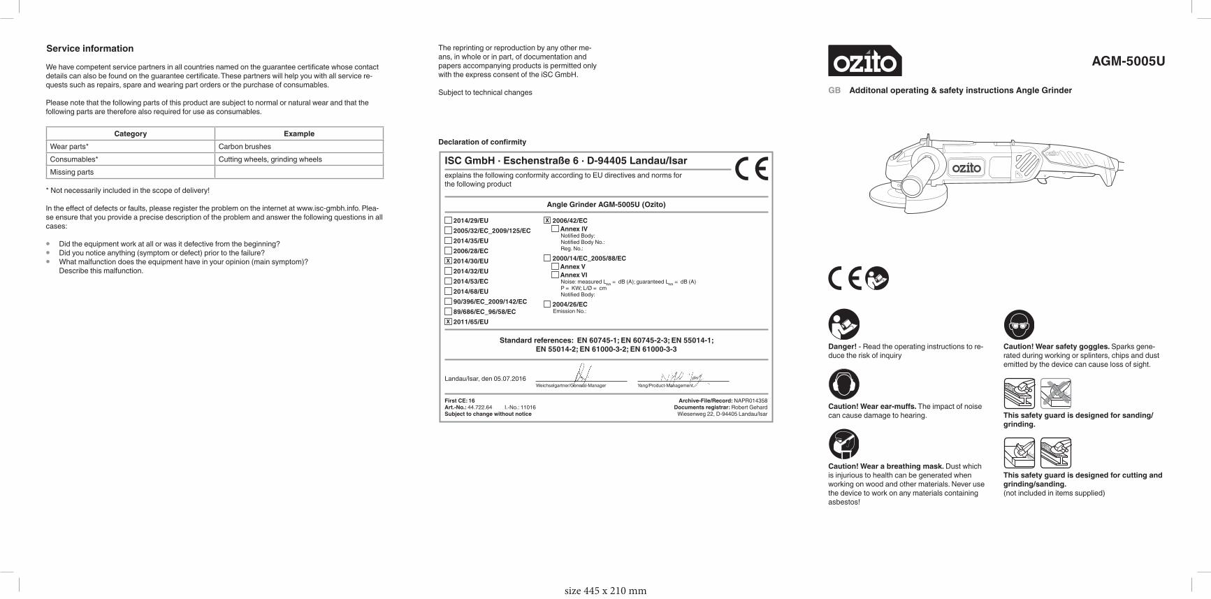
Danger! - Read the operating instructions to re-duce the risk of inquiry
Caution! Wear ear-muffs. The impact of noise can cause damage to hearing.
Caution! Wear a breathing mask. Dust which is injurious to health can be generated when working on wood and other materials. Never use the device to work on any materials containing asbestos!
Caution! Wear safety goggles. Sparks gene-rated during working or splinters, chips and dust emitted by the device can cause loss of sight.
This safety guard is designed for sanding/grinding.
This safety guard is designed for cutting and grinding/sanding.(not included in items supplied)
AGM-5005U
GB Additonal operating & safety instructions Angle Grinder
Yang/Product-ManagementWeichselgartner/General-Manager
- 135 -
explains the following conformity according to EU directives and norms for the following product
Angle Grinder AGM-5005U (Ozito)
2014/29/EU 2005/32/EC_2009/125/EC 2014/35/EU 2006/28/EC
X 2014/30/EU 2014/32/EU 2014/53/EC 2014/68/EU 90/396/EC_2009/142/EC 89/686/EC_96/58/EC
X 2011/65/EU
X 2006/42/EC Annex IVNotifi ed Body:Notifi ed Body No.:Reg. No.:
2000/14/EC_2005/88/EC Annex V Annex VINoise: measured LWA = dB (A); guaranteed LWA = dB (A)P = KW; L/Ø = cmNotified Body:
2004/26/ECEmission No.:
Standard references: EN 60745-1; EN 60745-2-3; EN 55014-1; EN 55014-2; EN 61000-3-2; EN 61000-3-3
Landau/Isar, den 05.07.2016
First CE: 16 Archive-File/Record: NAPR014358Art.-No.: 44.722.64 I.-No.: 11016 Documents registrar: Robert GehardSubject to change without notice Wiesenweg 22, D-94405 Landau/Isar
ISC GmbH · Eschenstraße 6 · D-94405 Landau/Isar
Declaration of confirmity
The reprinting or reproduction by any other me-ans, in whole or in part, of documentation and papers accompanying products is permitted only with the express consent of the iSC GmbH.
Subject to technical changes
Service information
We have competent service partners in all countries named on the guarantee certificate whose contact details can also be found on the guarantee certificate. These partners will help you with all service re-quests such as repairs, spare and wearing part orders or the purchase of consumables.
Please note that the following parts of this product are subject to normal or natural wear and that the following parts are therefore also required for use as consumables.
Category ExampleWear parts* Carbon brushesConsumables* Cutting wheels, grinding wheelsMissing parts
* Not necessarily included in the scope of delivery!
In the effect of defects or faults, please register the problem on the internet at www.isc-gmbh.info. Plea-se ensure that you provide a precise description of the problem and answer the following questions in all cases:
• Did the equipment work at all or was it defective from the beginning?• Did you notice anything (symptom or defect) prior to the failure?• What malfunction does the equipment have in your opinion (main symptom)?
Describe this malfunction.
size 445 x 210 mm
Items suppliedPlease check that the article is complete as specified in the scope of delivery. If parts are missing, please contact our service center or the sales outlet where you made your purchase at the latest within 5 working days after purchasing the product and upon presentation of a valid bill of purchase. Also, refer to the warranty table in the service information at the end of the operating instructions.• Open the packaging and take out the equip-
ment with care.• Remove the packaging material and any
packaging and/or transportation braces (if available).
• Check to see if all items are supplied.• Inspect the equipment and accessories for
transport damage.• If possible, please keep the packaging until
the end of the guarantee period.
Danger!The equipment and packaging material are not toys. Do not let children play with plastic bags, foils or small parts. There is a danger of swallowing or suffocating!
Proper useThe angle grinder is designed for grinding metal and stone when using the appropriate grinding wheel and guard.Warning! To cut metal and stone the grinder/san-der may only be used when the guard (available as an accessory) is mounted.
The equipment is to be used only for its prescri-bed purpose. Any other use is deemed to be a case of misuse. The user/operator and not the manufacturer will be liable for any damage or inju-ries of any kind caused as a result of this.
Please note that our equipment has not been de-signed for use in commercial, trade or industrial applications. Our warranty will be voided if the machine is used in commercial, trade or industrial businesses or for equivalent purposes.
Technical dataMains voltage: ........................230-240 V ~ 50 HzPower input: ............................................ 1010 WIdling speed: .......................................12,000/minMax. wheel diameter: ............................. 125 mmGrinding wheel: ...................... 125 x 22.2 x 6 mmCutting wheel: ........................ 125 x 22.2 x 3 mmMounting spindle thread: ............................. M 14Protection class: ...........................................II / &
Danger!Sound and vibrationSound and vibration values were measured in accordance with EN 60745.
LpA sound pressure level ................... 88.97 dB(A)KpA uncertainty .............................................3 dBLWA sound power level ..................... 99.97 dB(A)KWA uncertainty .............................................3 dB
Wear ear-muffs.The impact of noise can cause damage to hea-ring.
Total vibration values (vector sum of three direc-tions) determined in accordance with EN 60745.
Surface sanding/grinding:Vibration emission value ahAG = 14.08 m/s2
K uncertainty = 1.5 m/s2
The specified vibration value was established in accordance with a standardized testing method. It may change according to how the electric equip-ment is used and may exceed the specified value in exceptional circumstances.
The specified vibration value can be used to compare the equipment with other electric power tools.
The specified vibration value can be used for initi-al assessment of a harmful effect.
Keep the noise emissions and vibrations to a minimum.• Only use appliances which are in perfect wor-
king order.• Service and clean the appliance regularly.• Adapt your working style to suit the appliance.• Do not overload the appliance.• Have the appliance serviced whenever
necessary.• Switch the appliance off when it is not in use.• Wear protective gloves.
Caution!Residual risksEven if you use this electric power tool in ac-cordance with instructions, certain residual risks cannot be rules out. The following ha-zards may arise in connection with the equip-ment’s construction and layout:1. Lung damage if no suitable protective dust
mask is used.2. Damage to hearing if no suitable ear protecti-
on is used.3. Health damage caused by hand-arm vibra-
tions if the equipment is used over a pro-longed period or is not properly guided and maintained.
For EU countries only
Never place any electric power tools in your household refuse.
To comply with European Directive 2012/19/EC concerning old electric and electronic equipment and its implementation in national laws, old elec-tric power tools have to be separated from other waste and disposed of in an environment-friendly fashion, e.g. by taking to a recycling depot.
Recycling alternative to the return request:As an alternative to returning the equipment to the manufacturer, the owner of the electrical equipment must make sure that the equipment is properly disposed of if he no longer wants to keep the equipment. The old equipment can be returned to a suitable collection point that will dispose of the equipment in accordance with the national recycling and waste disposal regulations. This does not apply to any accessories or aids without electrical components supplied with the old equipment.