Embed Size (px)
Citation preview
114 Int. J. Nonlinear Dynamics and Control, Vol. 1, No. 1, 2017
Copyright © 2017 Inderscience Enterprises Ltd.
Active vibration control of an elevator system using magnetorheological damper actuator
Angelo M. Tusset* UTFPR-Ponta Grossa, PR, Department of Mathematics, Av. Monteiro Lobato, Km 04, s/no. CEP: 20 – 84016-210, Ponta Grossa-PR, Brazil Email: [email protected] *Corresponding author
Douglas R. Santo UNESP-Bauru, SP, Department of Mechanical Engineering, Av. Eng. Luiz Edmundo C. Coube 14-01 CEP: 17033-360, Bauru-SP, Brazil Email: [email protected]
Jose M. Balthazar UNESP-Bauru/ITA, SP, Mechanical Aeronautics Division, Praça Marechal Eduardo Gomes, 50, Vila das Acácias, CEP: 12.228-900 – São José dos Campos – SP, Brazil Email: [email protected]
Vinícius Piccirillo and Leandro C.C. Dos Santos UTFPR-Ponta Grossa, PR, Department of Mathematics, Av. Monteiro Lobato, Km 04, s/no. CEP: 20 – 84016-210, Ponta Grossa-PR, Brazil Email: [email protected] Email: [email protected]
Reyolando M.L.R.F. Brasil UFABC-Santo Andre, SP, Department of Aerospace Engineering/Aerospace Structures, Av. dos Estados, 5001, CEP: 09210-580, Santo André-SP, Brazil Email: [email protected]
Active vibration control of an elevator system 115
Abstract: We investigated the horizontal response of a vertical transportation with nonlinearities under excitation by guide rail deformations. A LQR control strategy was used in order to improve the comfort of passengers. To this end, a magnetorheological damper (MR damper) was used. The control force of the damper is a function of the voltage applied in the coil of the MR damper that is based on the force given by the controller. Numerical simulations were performed to investigate the nonlinear behaviour of the adopted mathematical model. Moreover, other issues such as robustness of the control technique were evaluated considering parametric errors and noise measurement. The results show that the LQR control strategy using MR damper can be effective in reducing the vibration of the vertical transport.
Keywords: optimal feedback control; vertical transportation; MR damper; high-speed elevator; parametric uncertainties; wavelet-based scale index; nonlinear model; chaos; LQR control; nonlinear dynamics.
Reference to this paper should be made as follows: Tusset, A.M., Santo, D.R., Balthazar, J.M., Piccirillo, V., Dos Santos, L.C.C. and Brasil, R.M.L.R.F. (2017) ‘Active vibration control of an elevator system using magnetorheological damper actuator’, Int. J. Nonlinear Dynamics and Control, Vol. 1, No. 1, pp.114–131.
Biographical notes: Angelo M. Tusset received his graduation’s degree in Mathematics from State College of Philosophy, Science and Letters União da Vitória (Brazil) in 1996. Moreover, he earned his Bachelor’s degree in Engineering of Automation and Control from University of Contestado (Brazil) in 2007. He received his Master’s degree from Northwest Regional University of Rio Grande do Sul (Brazil) in 2004. He received his PhD in Federal University of Rio Grande do Sul (Brazil) in 2008. Currently, he has been a Professor of Federal University of Technology – Paraná (UTFPR) in Ponta Grossa – Parana State, Brazil, in Department of Mathematics, Post-Graduation Program in Electrical Engineering (PPGEE-UTFPR-PG) and Post-Graduation Program in Mechanical Engineering (PPGEM-UTFPR-PG). He has experience in mechanical and electrical engineering areas, with emphasis on nonlinear phenomena, chaos and control. He is acting mainly on the following topics: linear and nonlinear control, nonlinear dynamics and intelligent materials.
Douglas R. Santo received his graduated in Physics from the Sao Paulo State University (Brazil) in 2012, during graduation he worked in modelling and dynamics of a micro-electromechanical device (MEMS). He received his Master degree in Mechanical Engineering from Sao Paulo State University (Brazil) in 2015, during the Master degree he worked in modelling, dynamics and vibration control of an elevator with chaotic behaviour. Currently, he is a Technological Development Analyst of the Line of X-Ray Diffraction 2 (XRD2) at the National Synchrotron Light. He is acting mainly on the following topics: modelling and projects of mechanical systems, mechanical vibrations, nonlinear dynamics and mechanical systems control.
Jose M. Balthazar graduated in Mathematics and Applied Mathematics in Sao Paulo State University (Brazil) in 1971. He received his Master degree in Science from Aeronautics Technological Institute (Brazil) in 1975, and PhD in Mechanical Engineering in Sao Paulo University (Brazil) in 1993. Currently, he is a Senior Visitor Professor in Mechanical Engineering Division of Aeronautics Technological Institute. In addition, he is a titular member of
116 A.M. Tusset et al.
Sao Paulo Academy of Science (ACIESP), Editor associated to South America of international journals: Advances in Vibration Engineering, Journal of Vibration and Control (JVC), the recent Journal of Nonlinear Dynamics and Control, and Modelling and Simulation in Engineering. He has experience in nonlinear dynamics, chaos and control with applications to engineering science and mechanics.
Vinícius Piccirillo graduated in Mathematics from Sao Paulo State University (Brazil) in 2005. He received his Master degree in Mechanical Engineering from Sao Paulo State University (Brazil) in 2007, and PhD in Aeronautics and Mechanical Engineering from Aeronautics Technological Institute in São José dos Campus-SP (Brazil) in 2012. Currently, he has been a Professor of Federal Technological University of Parana in Ponta Grossa-PR (Brazil) in Department of Mathematics. He has experience in mechanical engineering, with emphasis on non-linear phenomena and chaos. He is acting mainly on the following topics: shape memory alloys, nonlinear dynamics, analytical methods, perturbation techniques and linear feedback control.
Leandro C.C. Dos Santos graduated in Electronics Technology from the Federal University of Technology – Paraná, Ponta Grossa (Brazil) in 2006. He received his Bachelor in Electrical Engineering from Higher Education Center General Campos (CESCAGE), Ponta Grossa (Brazil) in 2015. He received his Master degree in Technology from Federal University of Technology-Paraná, Ponta Grossa (Brazil) in 2017. During his Master degree, he worked in modelling, dynamics and vibration control of an elevator considering the application of the magnetorheological damper. He has experience in electrical engineering, with emphasis on electrical systems. He is acting mainly on the following topics: electrical engineering, electronics, industrial automation, industrial instrumentation and maintenance management.
Reyolando M.L.R.F. Brasil graduated in Civil Engineering at the Mackenzie University (Brazil) in 1970. He received his Master degree in 1984 and PhD in 1990 in Civil Engineering from the Polytechnic School of the University of Sao Paulo (Brazil), where he retired in 2007 as an Associate Professor. Currently, he is a Full Professor of Aerospace Structures at the Federal University of ABC (Brazil) in the Center of Engineering, Modeling and Applied Social Sciences, Graduate Program in Mechanical Engineering (PPGEM-UFABC). He has experience in the areas of civil and mechanical engineering, with emphasis on structures, mainly in non-linear dynamics, dynamics of structures, non-ideal energy sources, experimental dynamic analysis of structures and vibration control.
1 Introduction
Nowadays, due to construction of high buildings, it is necessary the design of high-speed elevators, however, high speeds can result in decreases of quality of ride (Mitsui and Nara, 1971), this being one of the main problems in a high-speed elevator system (Nai et al., 1994). Thus, it is necessary to improve the travel quality, without losing the efficiency of elevator where there are limits on levels of horizontal and vertical vibrations, lateral and longitudinal acceleration and jerk, necessary to ensure good ride quality to passengers (Fortune, 1997). Kaczmarczyk and Picton (2013) used a traction drive elevator systems with long ropes and cables in order to analyse the high-rise
Active vibration control of an elevator system 117
structures. Benosman and Fukui (2014) have studied numerically the problem of elevator rope with sway motion due to external force disturbances through an active control, by using nonlinear controllers based on Lyapunov theory, to stabilise the rope sway dynamics. A model for transversal vibrations of an elevator cable system is studied in Sandilo and van Horssen (2015). Chang et al. (2011) investigated a high-speed elevator system in order to examine the characteristics of the excitations and analyse the dynamic responses due to horizontal vibration generated from the elevator wheels running on rough and winding guide rails. Yang et al. (2014) proposed an active control with time variant states using correlation filtered-X least mean square (co-FXLMS) algorithm and moving band pass filter (MBPF) has been proposed to control the cabin noise of the high-speed elevator. Arrasate et al. (2014) conducted a study of vertical vibrations caused by torque ripple generated at the elevator drive system and its influence in passenger comfort during an elevator travel. In Venkatesh et al. (2002) is presented a methodology for designing high-performance of the linear time-invariant (LTI) controller by elevator vertical motion for high-rise buildings with high-speed.
Motivated by necessity to improve passenger’s comfort level, this work presents a form of the controlling the dynamic horizontal behaviour of a three degrees of freedom model of a vertical transportation system excited through guide rail deformations by a controlled magnetorheological (MR) damper.
MR dampers, are widely used in the modern industry nowadays, and has capable of generating a force sufficient for rapid response in various applications (Truong and Ahn, 2011; Spelta et al., 2009). The magnetic properties permit its use as a damper, controlled by an electrical current (Tusset et al., 2009). Additionally, these devices offer highly reliable operations and their performance is relatively insensitive to temperature fluctuations or impurities in the fluid (Carlson and Weiss, 1994).
The MR damper can be used in the suppression of unwanted oscillations, which it can be controlled through the electrical current or voltage, which changes the viscosity of the fluid's internal damper. The damping force will depend on the speed of the piston of the damper and the density of internal fluid.
The feedback of state variables by means of sensors can provide information about the behaviour of the controlled system, over time and thereby on the optimal intensity of force being applied by the MR damper. Here, we will utilise a mathematical model to transform the values of control force in electric current signal, this model was proposed by Tusset et al. (2012).
The control strategy proposed in this paper contributes to the research in modelling and control of dynamic systems through the numerical display of control that uses an estimation strategy of the control signal and another technique for converting this control signal into an electrical signal that is applied on the physical actuator, it contributes directly to practical applications as the conversion of the estimated damping force signal through the application of optimal control (LQR) into electrical current signal enabling its application in the MR damper because the force control damping depends on the electric current applied to its coil.
2 Mathematical modelling
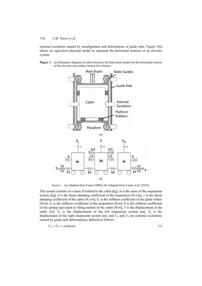
The schematic diagram of the cabin elevator is shown in Figure 1(a). The system consists of a roller guide supported by a platform with springs to avoid the transmission of the
118 A.M. Tusset et al.
external excitation caused by misalignment and deformation of guide rails. Figure 1(b) shows an equivalent physical model to represent the horizontal motions of an elevator system.
Figure 1 (a) Schematic diagram of cabin structure (b) Equivalent model for the horizontal motion of the elevator (see online version for colours)
(a)
(b)
Source: (a) Adapted from Funai (2004); (b) Adapted from Lopez et al. (2010)
The system consists of a mass M related to the cabin [kg], m is the mass of the suspension system [kg], b is the linear damping coefficient of the suspension [N.s/m], c is the linear damping coefficient of the cabin [N.s/m], k1 is the stiffness coefficient of the guide rollers [N/m], k2 is the stiffness coefficient of the suspension [N/m], k is the stiffness coefficient of the spring equivalent to tilting motion of the cabin [N/m], Y is the displacement of the cabin [m], YL is the displacement of the left suspension system [m], YR is the displacement of the right suspension system [m], and Ua and Ub are external excitations caused by guide rails deformations, defined as follows:
sin( )a bU U a ωt= = (1)
Active vibration control of an elevator system 119
where a and ω are the amplitude [m] and the external excitation frequency [rad/s] of the forced oscillation, respectively.
The equations of motion that represent the vertical transportation system can be formulated by considering the balance of forces acting on the masses as follows:
1 2 2 1
32 2 2
1 2 2 1
( )2 0
( )
L L L a
L R
R R R b
mY bY k k Y k Y k UMY cY k Y kY k Y k YmY bY k k Y k Y k U
+ + + − =
+ + + − − =
+ + + − =
(2)
The dimensional system of equations for the vertical transportation system can be written in state space form in the following form:
1 2
2 2 1 1 2 3 3 4
3 43
4 3 1 2 3 5 1 4 4 53
5 6
6 3 3 2 5 1 6 4
a
b
x xx x x x Ux xx x x x x xx xx x x x U
== − − + +== − − − +== − − +
α α α α
β β β β β
α α α α
(3)
where the system’s parameters are defined as follows:
1 21 2 3 4 5 6 1 2
2 1 2 2 23 4 1 2 3 4 5
( ), , , , , , , ,
2, , , , , , .
L L R Rb k kx Y x Y x Y x Y x Y x Ym m
k k c k k k km m M M M M M
+= = = = = = = =
= = = = = = =
α α
α α β β β β β
3 A wavelet-based scale index
In recent years some classical systems, such as the logistic map, Henon map, Bonhoeffer-van der Pol oscillator (Benítez et al., 2010), Rössler system (Akhshani et al., 2014), SMA oscillators (Piccirillo et al., 2016) and the heartbeat dynamics (Behnia et al., 2013) have been analysed by the Scale index.
The wavelet transform of a one-dimensional (1D) signal consists of the development into a basis constructed via solutions like functions called wavelet, using various internal transformations and shifts (Awrejcewicz et al., 2009). Given f ∈ L2(Ñ), the continuous wavelet transform (CWT) of f at time v, scale s and time location t is defined as
( ) ( ) ( )* *, ,, : , v s v sWf v s f f t t dt
+∞∫
−∞= =ψ ψ (4)
where
,1 , , 0v s
t v v sss−⎛ ⎞= ∈ >⎜ ⎟
⎝ ⎠ψ ψ (5)
120 A.M. Tusset et al.
and Wf(v, s) provides the frequency component of the signal of f at time v and scale s with respect to some analysing wavelet ψv,s.
The scalogram of f, ℘, is defined as follows (Benítez et al., 2010):
( ) ( )1/22
( ) : , ,s Wf v s Wf v s dv+∞∫
−∞
⎛ ⎞℘ = = ⎜ ⎟⎝ ⎠
(6)
℘(s) is the energy of the CWT of f at scale s. The scalogram is a useful tool for studying a signal, since it allows the detection of its most representative scales (or frequencies). Then, the innerscalogram of f at scale s can be defined by (Benítez et al., 2010):
( ) ( ) ( )1/2( ) 2
( )( ) : , ,
d sinnerJ s c s
s Wf v s Wf v s dv∫⎛ ⎞℘ = = ⎜ ⎟⎝ ⎠
(7)
where J(s) = [c(s), d(s)] ⊆ I is the maximal subinterval in I for which the supported of ψu,s is included in I for all u ∈ J(s) (Benítez et al., 2010). As regards the length of J(s) depends on the scale s, so that the values of the inner scalogram at different scales cannot be com-pared. Therefore, the inner scalogram should be normalised as follows (Benítez et al., 2010):
( )1/2( )( )
( ) ( )
innerinner ss
d s c s
℘℘ =−
(8)
The Scale index in the scale interval [s0, s1] can be defined by the quotient (Benítez et al., 2010)
( )( )
min
max:scale
si
s℘
=℘
(9)
where smax is the smallest scale such that ℘(s) ≤ ℘(smax) for all s ∈ [s0, s1], and smin the smallest scale such that ℘(smin) ≤ ℘(s). Note that for compactly supported signals only the normalised inner scalogram will be considered (Benítez et al., 2010).
From its definition, the scale index iscale is such that 0 ≤ iscale ≤ 1 and it can be interpreted as a measure of the degree of non-periodicity of the signal: the scale index will be zero or close to zero for periodic sequences and close to one for highly non-periodic sequences (Benítez et al., 2010).
3.1 Numerical simulation
The parameters used in numerical simulations were experimentally obtained in Lopez et al. (2010), and are given in Table 1.
Active vibration control of an elevator system 121
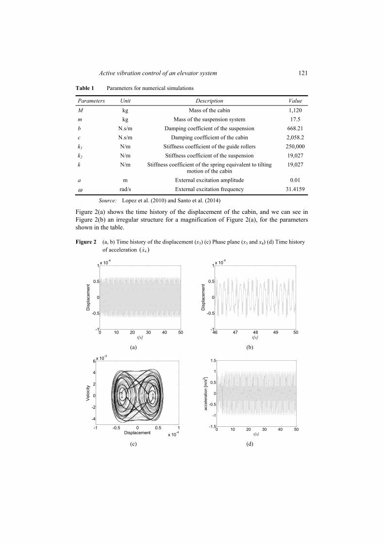
Table 1 Parameters for numerical simulations
Parameters Unit Description Value M kg Mass of the cabin 1,120 m kg Mass of the suspension system 17.5 b N.s/m Damping coefficient of the suspension 668.21 c N.s/m Damping coefficient of the cabin 2,058.2 k1 N/m Stiffness coefficient of the guide rollers 250,000 k2 N/m Stiffness coefficient of the suspension 19,027 k N/m Stiffness coefficient of the spring equivalent to tilting
motion of the cabin 19,027
a m External excitation amplitude 0.01
ω rad/s External excitation frequency 31.4159
Source: Lopez et al. (2010) and Santo et al. (2014)
Figure 2(a) shows the time history of the displacement of the cabin, and we can see in Figure 2(b) an irregular structure for a magnification of Figure 2(a), for the parameters shown in the table.
Figure 2 (a, b) Time history of the displacement (x3) (c) Phase plane (x3 and x4) (d) Time history of acceleration 4( )x
0 10 20 30 40 50-1
-0.5
0
0.5
1x 10⁻⁴
t[s]
Dis
plac
emen
t
46 47 48 49 50-1
-0.5
0
0.5
1x 10⁻⁴
t[s]
Dis
plac
emen
t
(a) (b)
-1 -0.5 0 0.5 1x 10⁻⁴
-4
-2
0
2
4
6x 10⁻³
Displacement
Vel
ocity
0 10 20 30 40 50-1.5
-1
-0.5
0
0.5
1
1.5
t[s]
acce
lera
tion
[m/s
2 ]
(c) (d)
122 A.M. Tusset et al.
Here, scale index was obtained using the Daubechies eight-wavelet (db8) function and the scale interval from s0 = 1 to s1 = 512. As can be seen from the figure that the displacement of (x3), has a non-periodic behaviour comproved by the index scale (iscale = 0.1134), and the acceleration which passengers are exposed is close to 1.02[m/s2].
As proposed by Griffin (1990), the peak acceleration values between 0.01[m/s2] and 10[m/s2] can cause some discomfort to the human body. After analysing the results obtained in Figure 2 we can see that the peak value is within the range of interest of vibration on the human body.
3.2 Analysis of the level of exposition to vibration
Griffin (1990), suggests that the level of exposure to vibration can be estimated by calculating the root mean square (rms):
21irms X
N⎛ ⎞= ⎜ ⎟⎝ ⎠∑ (10)
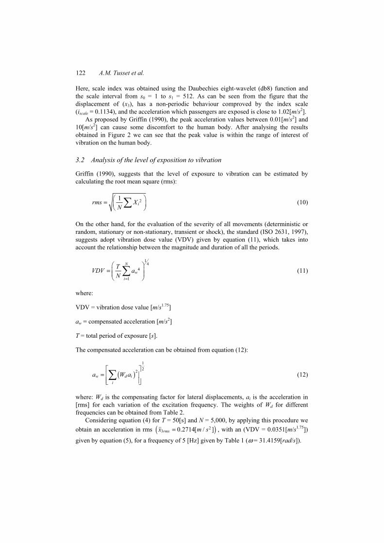
On the other hand, for the evaluation of the severity of all movements (deterministic or random, stationary or non-stationary, transient or shock), the standard (ISO 2631, 1997), suggests adopt vibration dose value (VDV) given by equation (11), which takes into account the relationship between the magnitude and duration of all the periods.
14
4
1
N
wi
TVDV aN =
⎛ ⎞= ⎜ ⎟⎜ ⎟⎝ ⎠∑ (11)
where:
VDV = vibration dose value [m/s1.75]
aw = compensated acceleration [m/s2]
T = total period of exposure [s].
The compensated acceleration can be obtained from equation (12):
( )122
w d ii
a W a⎡ ⎤
= ⎢ ⎥⎢ ⎥⎣ ⎦∑ (12)
where: Wd is the compensating factor for lateral displacements, ai is the acceleration in [rms] for each variation of the excitation frequency. The weights of Wd for different frequencies can be obtained from Table 2.
Considering equation (4) for T = 50[s] and N = 5,000, by applying this procedure we obtain an acceleration in rms ( )2
3 0.2714[ / ]rmsx m s= , with an (VDV = 0.0351[m/s1.75])
given by equation (5), for a frequency of 5 [Hz] given by Table 1 (ω = 31.4159[rad/s]).
Active vibration control of an elevator system 123
Table 2 Compensation factors Wd
Frequency [Hz] Wd (×103) Frequency [Hz] Wd (×103) 1 1,011 10 212 1.25 1,008 12, 5 161 1.6 968 16 125 2 890 20 100 2.5 776 25 80 3.15 642 31, 5 63.2 4 512 40 49.4 5 409 50 38.8 6.3 323 63 29.5 8 253 80 21.1
Source: ISO 2631-1 (1997)
4 Reduction of the level of exposition to vibration by MR damper
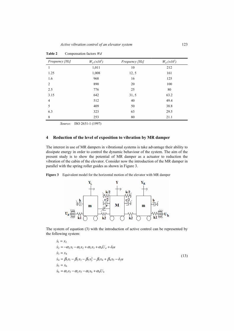
The interest in use of MR dampers in vibrational systems is take advantage their ability to dissipate energy in order to control the dynamic behaviour of the system. The aim of the present study is to show the potential of MR damper as a actuator to reduction the vibration of the cabin of the elevator. Consider now the introduction of the MR damper in parallel with the spring roller guides as shown in Figure 3.
Figure 3 Equivalent model for the horizontal motion of the elevator with MR damper
The system of equation (3) with the introduction of active control can be represented by the following system:
1 2
2 2 1 1 2 3 3 4 1
3 43
4 3 1 2 3 5 1 4 4 5 23
5 6
6 3 3 2 5 1 6 4
a
b
x xx x x x U δ ux xx x x x x x δ ux xx x x x U
== − − + + +== − − − + −== − − +
α α α α
β β β β β
α α α α
(13)
124 A.M. Tusset et al.
where u represent the MR damper force, and 11δm
= and 21δM
= .
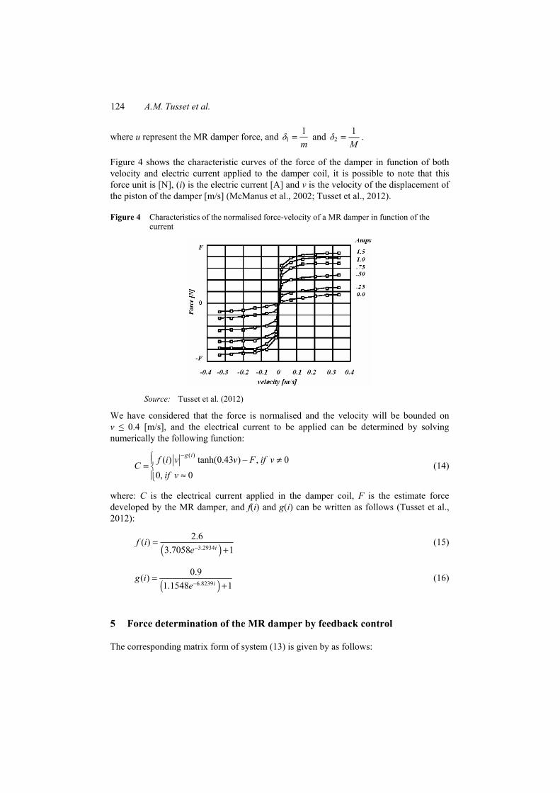
Figure 4 shows the characteristic curves of the force of the damper in function of both velocity and electric current applied to the damper coil, it is possible to note that this force unit is [N], (i) is the electric current [A] and v is the velocity of the displacement of the piston of the damper [m/s] (McManus et al., 2002; Tusset et al., 2012).
Figure 4 Characteristics of the normalised force-velocity of a MR damper in function of the current
Source: Tusset et al. (2012)
We have considered that the force is normalised and the velocity will be bounded on v ≤ 0.4 [m/s], and the electrical current to be applied can be determined by solving numerically the following function:
( )( ) tanh(0.43 ) , 00, 0
g if i v v F if vCif v
−⎧ − ≠⎪= ⎨≈⎪⎩
(14)
where: C is the electrical current applied in the damper coil, F is the estimate force developed by the MR damper, and f(i) and g(i) can be written as follows (Tusset et al., 2012):
( )3.2934
2.6( )3.7058 1i
f ie−
=+
(15)
( )6.8239
0.9( )1.1548 1i
g ie−
=+
(16)
5 Force determination of the MR damper by feedback control
The corresponding matrix form of system (13) is given by as follows:
Active vibration control of an elevator system 125
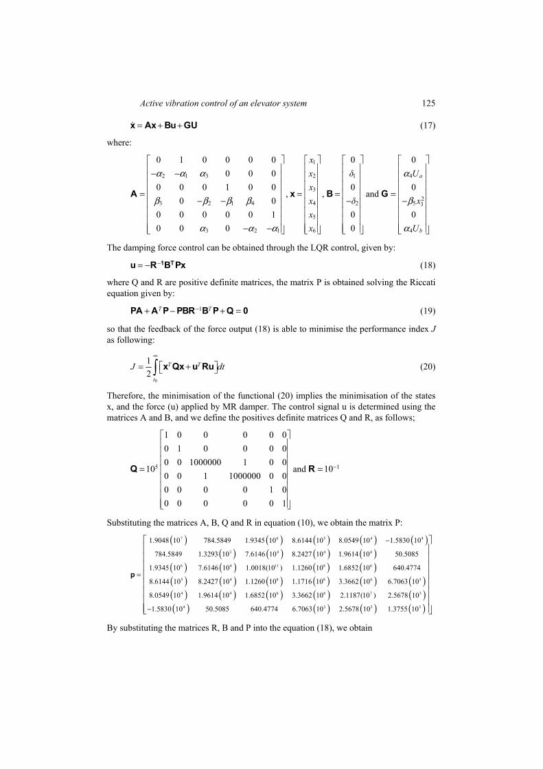
= + +x Ax Bu GU (17)
where:
1
2 1 3 2 1 4
32
3 2 1 4 4 2 5 3
5
3 2 1 6 4
0 1 0 0 0 0 0 00 0 0
0 0 0 1 0 0 0 0, , and
0 00 0 0 0 0 1 0 00 0 0 0
a
b
xx δ Uxx δ xxx U
⎡ ⎤ ⎡ ⎤ ⎡ ⎤ ⎡ ⎤⎢ ⎥ ⎢ ⎥ ⎢ ⎥ ⎢ ⎥− −⎢ ⎥ ⎢ ⎥ ⎢ ⎥ ⎢ ⎥⎢ ⎥ ⎢ ⎥ ⎢ ⎥ ⎢ ⎥
= = = =⎢ ⎥ ⎢ ⎥ ⎢ ⎥ ⎢ ⎥− − − −⎢ ⎥ ⎢ ⎥ ⎢ ⎥ ⎢ ⎥⎢ ⎥ ⎢ ⎥ ⎢ ⎥ ⎢ ⎥⎢ ⎥ ⎢ ⎥ ⎢ ⎥ ⎢ ⎥
− −⎢ ⎥ ⎢ ⎥ ⎢ ⎥ ⎢ ⎥⎣ ⎦ ⎣ ⎦ ⎣ ⎦ ⎣ ⎦
A x B G
α α α α
β β β β β
α α α α
The damping force control can be obtained through the LQR control, given by: −= − 1 Tu R B Px (18)
where Q and R are positive definite matrices, the matrix P is obtained solving the Riccati equation given by:
1T T−+ − + =PA A P PBR B P Q 0 (19)
so that the feedback of the force output (18) is able to minimise the performance index J as following:
0
12
T T
t
J dt∞
⎡ ⎤= +⎣ ⎦∫ x Qx u Ru (20)
Therefore, the minimisation of the functional (20) implies the minimisation of the states x, and the force (u) applied by MR damper. The control signal u is determined using the matrices A and B, and we define the positives definite matrices Q and R, as follows;
5 1
1 0 0 0 0 00 1 0 0 0 00 0 1000000 1 0 0
10 and 100 0 1 1000000 0 00 0 0 0 1 00 0 0 0 0 1
−
⎡ ⎤⎢ ⎥⎢ ⎥⎢ ⎥
= =⎢ ⎥⎢ ⎥⎢ ⎥⎢ ⎥⎢ ⎥⎣ ⎦
Q R
Substituting the matrices A, B, Q and R in equation (10), we obtain the matrix P:
( ) ( ) ( ) ( ) ( )( ) ( ) ( ) ( )
( ) ( ) ( ) ( )( ) ( ) ( ) ( )
7 6 5 4 4
3 4 4 4
6 4 11 8 6
5 4 8 8
1.9048 10 784.5849 1.9345 10 8.6144 10 8.0549 10 1.5830 10
784.5849 1.3293 10 7.6146 10 8.2427 10 1.9614 10 50.5085
1.9345 10 7.6146 10 1.0018(10 ) 1.1260 10 1.6852 10 640.4774
8.6144 10 8.2427 10 1.1260 10 1.1716 10 3
−
=p ( ) ( )( ) ( ) ( ) ( ) ( )( ) ( ) ( ) ( )
6 3
4 4 6 6 7 3
4 3 3 3
.3662 10 6.7063 10
8.0549 10 1.9614 10 1.6852 10 3.3662 10 2.1187(10 ) 2.5678 10
1.5830 10 50.5085 640.4774 6.7063 10 2.5678 10 1.3755 10−
⎡ ⎤⎢ ⎥⎢ ⎥⎢ ⎥⎢ ⎥⎢ ⎥⎢ ⎥⎢ ⎥⎢ ⎥⎣ ⎦
By substituting the matrices R, B and P into the equation (18), we obtain
126 A.M. Tusset et al.
1 2 3 4 5 67243.1294 23.6365 961849.1073 998972.4480 18847.0373 31.0160u x x x x x x= − + + + + (21)
Figures 5 and 6 show the behaviour of the elevator cabin, considering the proposed control.
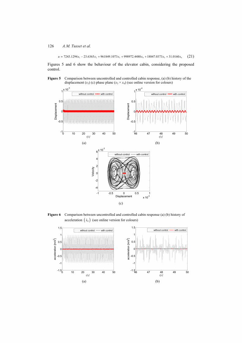
Figure 5 Comparison between uncontrolled and controlled cabin response, (a) (b) history of the displacement (x3) (c) phase plane (x3 × x4) (see online version for colours)
0 10 20 30 40 50-1
-0.5
0
0.5
1x 10⁻⁴
t[s]
Dis
plac
emen
t
without control with control
46 47 48 49 50
-1
-0.5
0
0.5
1x 10⁻⁴
t[s]
Dis
plac
emen
t
without control with control
(a) (b)
-1 -0.5 0 0.5 1x 10⁻⁴
-4
-2
0
2
4
6x 10⁻³
Displacement
Velo
city
without control with control
(c)
Figure 6 Comparison between uncontrolled and controlled cabin response (a) (b) history of acceleration ( )4x (see online version for colours)
0 10 20 30 40 50-1.5
-1
-0.5
0
0.5
1
1.5
t[s]
acce
lera
tion
[m/s
2 ]
without control with control
46 47 48 49 50
-1.5
-1
-0.5
0
0.5
1
1.5
t[s]
acce
lera
tion
[m/s
2 ]
without control with control
(a) (b)
Active vibration control of an elevator system 127
It is possible to observe that the proposed control reduces the system oscillation amplitude (Figure 5). The rms of the magnitude acceleration peak has been reduced in about 98.6367% (Figure 6), where the uncontrolled system acceleration ( )3 0.2714rmsx =
was reduced to ( )3 0.0037rmsx = when the MR damper was introduced into the system. At the same time the decrease in the VDV is observed, that is, the
VDV = 0.0047[m/s1.75] for the proposed control system (17), and thus reducing the (VDV) of the uncontrolled system in 98.661%.
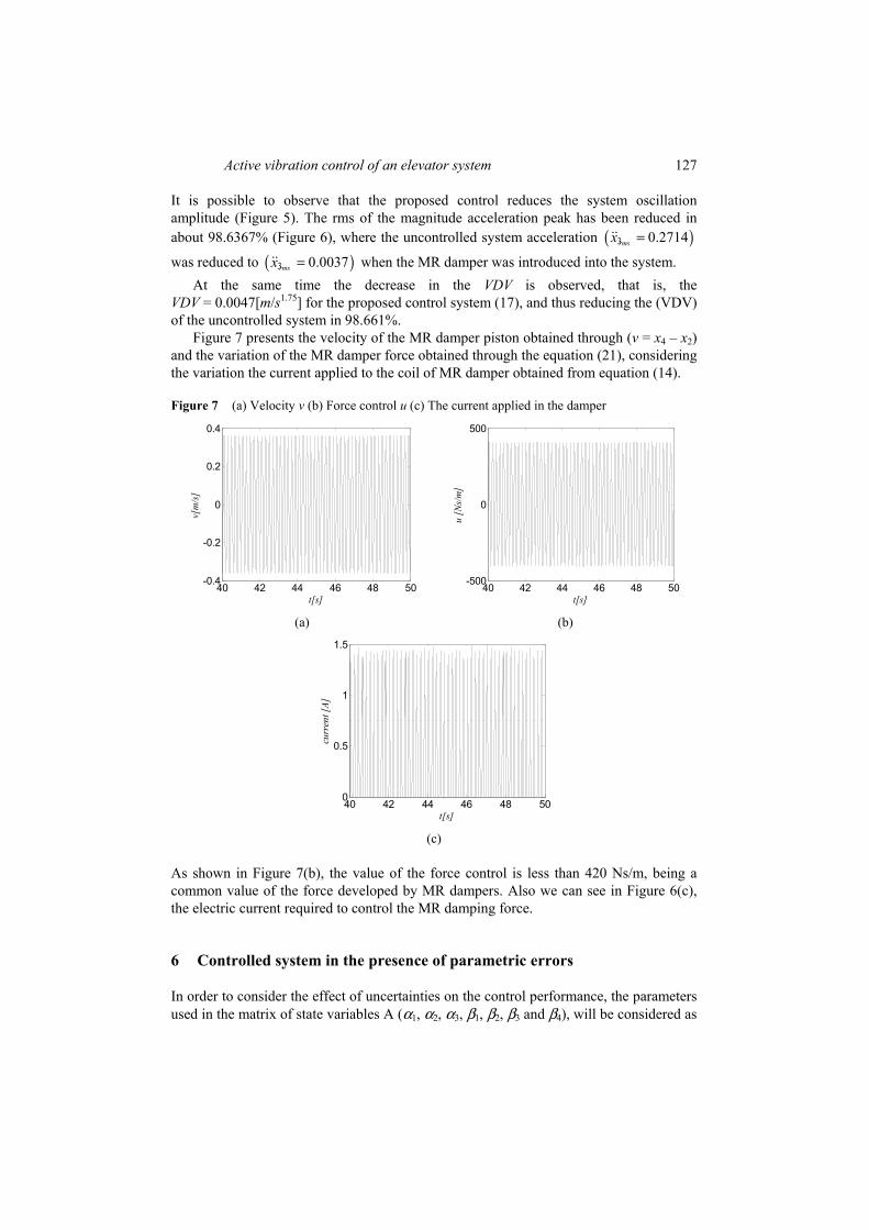
Figure 7 presents the velocity of the MR damper piston obtained through (v = x4 – x2) and the variation of the MR damper force obtained through the equation (21), considering the variation the current applied to the coil of MR damper obtained from equation (14).
Figure 7 (a) Velocity v (b) Force control u (c) The current applied in the damper
40 42 44 46 48 50-0.4
-0.2
0
0.2
0.4
t[s]
v[m
/s]
40 42 44 46 48 50-500
0
500
t[s]
u [N
s/m
]
(a) (b)
40 42 44 46 48 500
0.5
1
1.5
t[s]
curr
ent [
A]
(c)
As shown in Figure 7(b), the value of the force control is less than 420 Ns/m, being a common value of the force developed by MR dampers. Also we can see in Figure 6(c), the electric current required to control the MR damping force.
6 Controlled system in the presence of parametric errors
In order to consider the effect of uncertainties on the control performance, the parameters used in the matrix of state variables A (α1, α2, α3, β1, β2, β3 and β4), will be considered as
128 A.M. Tusset et al.
a random error of ±20%, this strategy is similar to previously described method used in (Nozaki et al., 2013; Tusset et al., 2016; Balthazar et al., 2014).
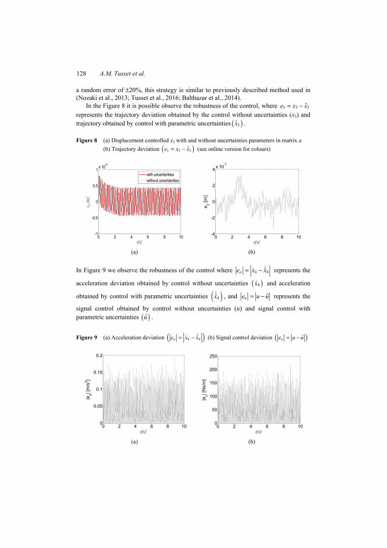
In the Figure 8 it is possible observe the robustness of the control, where 3 3 3ˆe x x= − represents the trajectory deviation obtained by the control without uncertainties (x3) and trajectory obtained by control with parametric uncertainties ( )3x .
Figure 8 (a) Displacement controlled x3 with and without uncertainties parameters in matrix a (b) Trajectory deviation ( )3 3 3ˆe x x= − (see online version for colours)
0 2 4 6 8 10-1
-0.5
0
0.5
1 x 10⁻⁵
t[s]
x 3 [m]
with uncertaintieswithout uncertainties
0 2 4 6 8 10-4
-2
0
2
4 x 10⁻⁷
t[s]
e 3 [m]
(a) (b)
In Figure 9 we observe the robustness of the control where 4 4ˆae x x= − represents the
acceleration deviation obtained by control without uncertainties ( )4x and acceleration
obtained by control with parametric uncertainties ( )4x , and ˆue u u= − represents the
signal control obtained by control without uncertainties (u) and signal control with parametric uncertainties ( )u .
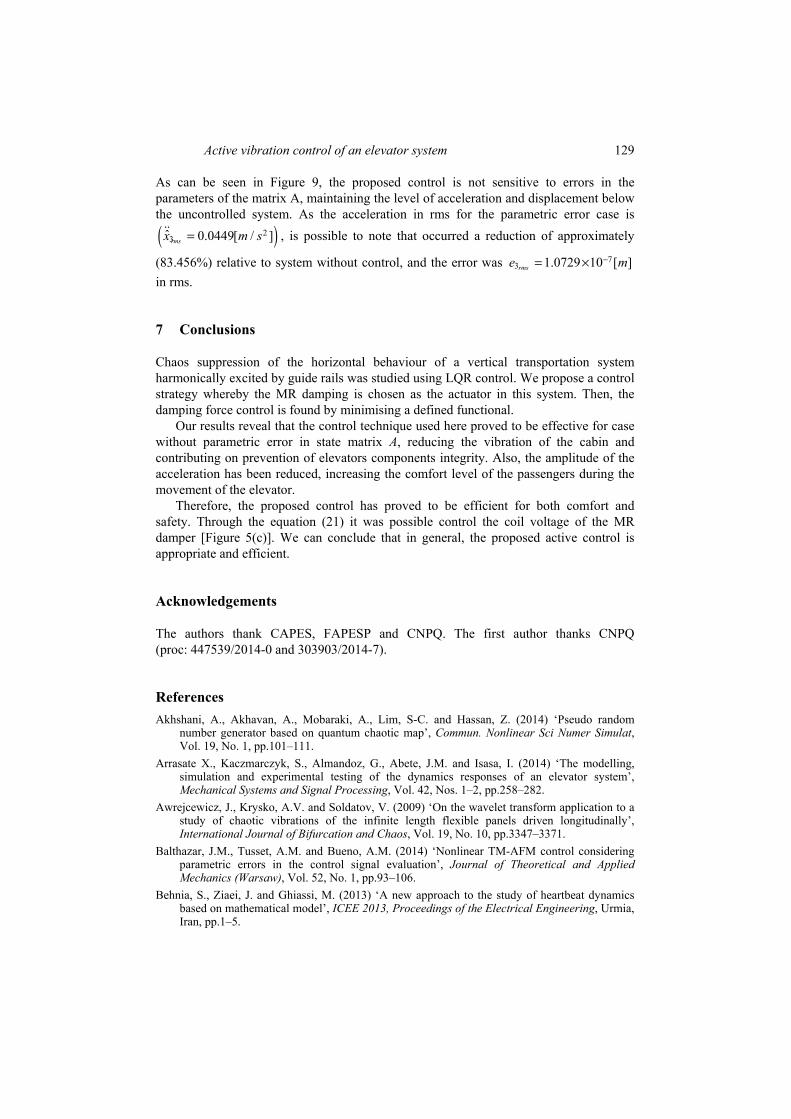
Figure 9 (a) Acceleration deviation ( )4 4ˆae x x= − (b) Signal control deviation ( )ˆue u u= −
0 2 4 6 8 100
0.05
0.1
0.15
0.2
t[s]
|ea| [
m/s
2 ]
0 2 4 6 8 100
50
100
150
200
250
t[s]
|eu| [
Ns/
m]
(a) (b)
Active vibration control of an elevator system 129
As can be seen in Figure 9, the proposed control is not sensitive to errors in the parameters of the matrix A, maintaining the level of acceleration and displacement below the uncontrolled system. As the acceleration in rms for the parametric error case is
( )23ˆ 0.0449[ / ]rmsx m s= , is possible to note that occurred a reduction of approximately
(83.456%) relative to system without control, and the error was 73 1.0729 10 [ ]rmse m−= ×
in rms.
7 Conclusions
Chaos suppression of the horizontal behaviour of a vertical transportation system harmonically excited by guide rails was studied using LQR control. We propose a control strategy whereby the MR damping is chosen as the actuator in this system. Then, the damping force control is found by minimising a defined functional.
Our results reveal that the control technique used here proved to be effective for case without parametric error in state matrix A, reducing the vibration of the cabin and contributing on prevention of elevators components integrity. Also, the amplitude of the acceleration has been reduced, increasing the comfort level of the passengers during the movement of the elevator.
Therefore, the proposed control has proved to be efficient for both comfort and safety. Through the equation (21) it was possible control the coil voltage of the MR damper [Figure 5(c)]. We can conclude that in general, the proposed active control is appropriate and efficient.
Acknowledgements
The authors thank CAPES, FAPESP and CNPQ. The first author thanks CNPQ (proc: 447539/2014-0 and 303903/2014-7).
References Akhshani, A., Akhavan, A., Mobaraki, A., Lim, S-C. and Hassan, Z. (2014) ‘Pseudo random
number generator based on quantum chaotic map’, Commun. Nonlinear Sci Numer Simulat, Vol. 19, No. 1, pp.101–111.
Arrasate X., Kaczmarczyk, S., Almandoz, G., Abete, J.M. and Isasa, I. (2014) ‘The modelling, simulation and experimental testing of the dynamics responses of an elevator system’, Mechanical Systems and Signal Processing, Vol. 42, Nos. 1–2, pp.258–282.
Awrejcewicz, J., Krysko, A.V. and Soldatov, V. (2009) ‘On the wavelet transform application to a study of chaotic vibrations of the infinite length flexible panels driven longitudinally’, International Journal of Bifurcation and Chaos, Vol. 19, No. 10, pp.3347–3371.
Balthazar, J.M., Tusset, A.M. and Bueno, A.M. (2014) ‘Nonlinear TM-AFM control considering parametric errors in the control signal evaluation’, Journal of Theoretical and Applied Mechanics (Warsaw), Vol. 52, No. 1, pp.93–106.
Behnia, S., Ziaei, J. and Ghiassi, M. (2013) ‘A new approach to the study of heartbeat dynamics based on mathematical model’, ICEE 2013, Proceedings of the Electrical Engineering, Urmia, Iran, pp.1–5.
130 A.M. Tusset et al.
Benítez, R., Bolós, V.J. and Ramírez, M.E. (2010) ‘A wavelet-based tool for studying non-periodicity’, Computers and Mathematics with Applications, Vol. 60, No. 3, pp.634–641.
Benosman, M. and Fukui, D. (2014) ‘Lyapunov-based control of the sway dynamics for elevator ropes’, IEEE Transactions on Control Systems Technology, Vol. 22, No.5, pp.1855–1863.
Carlson, J.D. and Weiss, K.D. (1994) ‘A growing attraction to magnetic fluids’, Journal Machine Design, Vol. 66, No. 15, pp.61–64.
Chang, C.C., Lin, C.C., Su, W.C. and Huang, Y.P. (2011) ‘H∞ direct output feedback control of high-speed elevator systems’, ASME 2011 Pressure Vessels and Piping Conference: Seismic Engineering 8, Baltimore, Maryland, USA, pp.289–296.
Fortune, J.W. (1997) ‘Mega-high-rise elevatoring’, Elevator World, Vol. 45, No. 12, pp.128–135. Funai, K. (2004) ‘The development of active vibration damper for super high-speed elevators’,
Lift Report, Vol. 5, No. 1, pp.22–37. Griffin, M.J. (1990) Handbook of Human Vibration, Academic Press, U.S.A. ISO 2631-1 (1997) Mechanical Vibration and Shock – Evaluation of Human Exposure to
Whole-Body Vibration – Part I: General Requirements, International Standard, Geneva. Kaczmarczyk, S. and Picton, P. (2013) ‘The prediction of nonlinear responses and active stiffness
control of moving slender continua subjected to dynamic loadings in a vertical host structure’, International Journal of Acoustics and Vibration, Vol. 18, No. 1, pp.39–44.
Lopez, S.M.R., Perondi, E.A. and Sobrinho, M.R.S. (2010) ‘Adaptive control for an active suspension of an elevator’, ABCM Symposium Series in Mechatronics, Gramado, Brazil, Vol. 4, pp.62–71.
McManus, S.J., St. Clair, A., Boileau, P.E., Boutin, J. and Rakheja, S. (2002) ‘Evaluation of vibration and shock attenuation performance of a suspension seat with a semi-active magnetorheological fluid damper’, Journal of Sound and Vibration, Vol. 253, No. 1, pp.313–327.
Mitsui, N. and Nara, T. (1971) ‘Analysis of horizontal quaking of high-speed elevators’, Hitachi Review, Vol. 20, No. 8, pp.342–348.
Nai, K., Forsythe, W. and Goodall, R.M. (1994) ‘Vibration reduction techniques for high speed passenger elevators’, Proceedings of the Third IEEE Conference on Control Applications, pp.965–970.
Nozaki, R., Balthazar, J.M., Tusset, A.M., Pontes, B.R., and Bueno, A.M. (2013) ‘Nonlinear control system applied to atomic force microscope including parametric errors’, Journal of Control, Automation and Electrical Systems, Vol. 24, No. 3, pp.223–231.
Piccirillo, V., Balthazar, J.M., Tusset, A.M., Bernardini, D. and Rega, G. (2016) ‘Characterizing the nonlinear behavior of a pseudoelastic oscillator via the wavelet transform’, Proceedings of the Institution of Mechanical Engineers, Part C: Journal of Mechanical Engineering Science, Vol. 230, No. 1, pp.120–132.
Sandilo, S.H. and van Horssen, W.T. (2015) ‘On a cascade of autoresonances in an elevator cable system’, Nonlinear Dynamics, Vol. 80, No. 3, pp.1613–1630.
Santo, D.R., Balthazar, J.M., Pontes Jr., B.R., Silveira, M. and Tusset, A.M. (2014) ‘Dinâmica do movimento horizontal de um sistema de transporte vertical excitado harmonicamente pelos trilhos de guia’, CONEM: Proceedings of the Congresso Nacional de Engenharia Mecânica, Uberlândia, Brazil, pp.1–10.
Spelta, C., Previdi, F., Savaresi, S.M., Fraternale, G. and Gaudiano, N. (2009) ‘Control of magnetorheological dampers for vibration reduction in a washing machine’, Mechatronics, Vol. 19, No. 3, pp.410–421.
Truong, D.Q. and Ahn, K.K. (2011) ‘Nonlinear black-box models and force-sensorless damping control for damping systems using magneto-rheological fluid dampers’, Sensors and Actuators A, Vol. 167, No. 2, pp.556–573.
Tusset, A.M., Balthazar, J.M., Chavarette, F.R. and Felix, J.L.P. (2012) ‘On energy transfer phenomena, in a nonlinear ideal and nonideal essential vibrating systems, coupled to a (MR) magneto-rheological damper’, Nonlinear Dynamics, Vol. 69, No. 4, pp.1859–1880.
Active vibration control of an elevator system 131
Tusset, A.M., Piccirillo, V., Bueno, A.M., Balthazar, J.M., Sado, D., Felix, J.L.P. and Brasil, R.M.L.R.D.F. (2016) ‘Chaos control and sensitivity analysis of a double pendulum arm excited by an RLC circuit based nonlinear shaker’, Journal of Vibration and Control, Vol. 22, No. 17, pp.3621–3637.
Tusset, A.M., Rafikov, M. and Balthazar, J.M. (2009) ‘An intelligent controller design for magnetorheological damper based on quarter-car model’, Journal of Vibration and Control, Vol. 15, No. 12, pp.1907–1920.
Venkatesh, S.R., Cho, Y.M. and Kim, J. (2002) ‘Robust control of vertical motions in ultra-high rise elevators’, Control Engineering Practice, Vol. 10, No. 2, pp.121–132.
Yang. I.H., Jeong J.E., Jeong, U.C., Kim, J.S. and Oh, J.E. (2014) ‘Improvement of noise reduction performance for a high-speed elevator using modified active noise control’, Applied Acoustics, Vol. 79, No. 1, pp.58–68.