Embed Size (px)
Citation preview
Anesthesia Machine Anesthesia Machine
Presented by Gil Soto C.R.N.APresented by Gil Soto C.R.N.A

DangerDanger
Unpleasant SurprisesUnpleasant Surprises
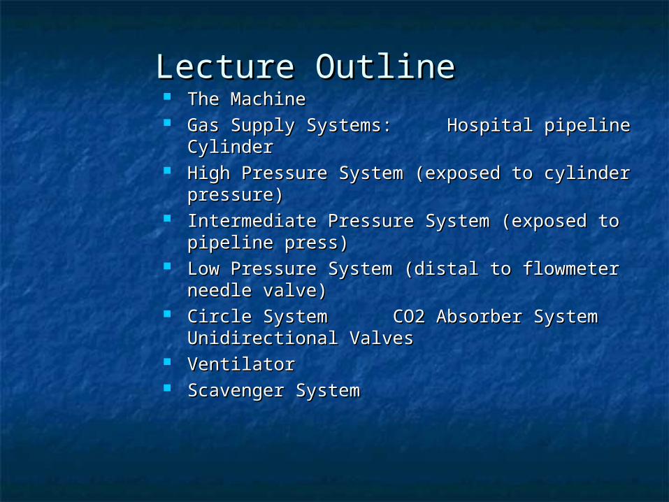
Lecture OutlineLecture Outline The MachineThe Machine Gas Supply Systems:Gas Supply Systems:
Hospital pipelineHospital pipelineCylinderCylinder
High Pressure System (exposed to cylinder pressure)High Pressure System (exposed to cylinder pressure) Intermediate Pressure System (exposed to pipeline Intermediate Pressure System (exposed to pipeline
press)press) Low Pressure System (distal to flowmeter needle Low Pressure System (distal to flowmeter needle
valve)valve) Circle SystemCircle System
CO2 Absorber System CO2 Absorber System Unidirectional Valves Unidirectional Valves
VentilatorVentilator Scavenger SystemScavenger System
Anesthesia Machine Anesthesia Machine CheckoutCheckout
General:General: Anesthesia Apparatus Checkout Recommendations, 1993 (Taken from the Anesthesia Apparatus Checkout Recommendations, 1993 (Taken from the
FDA) FDA) This checkout, or a reasonable equivalent, should be conducted before This checkout, or a reasonable equivalent, should be conducted before
administration of anesthesia. These recommendations are only valid for an administration of anesthesia. These recommendations are only valid for an anesthesia system that conforms to current and relevant standards and anesthesia system that conforms to current and relevant standards and includes an ascending bellows ventilator and at least the following includes an ascending bellows ventilator and at least the following monitors: capnograph, pulse oximeter, oxygen analyzer, respiratory monitors: capnograph, pulse oximeter, oxygen analyzer, respiratory volume monitor (spirometer) and breathing system pressure monitor with volume monitor (spirometer) and breathing system pressure monitor with high and low pressure alarms. This is a guideline which users are high and low pressure alarms. This is a guideline which users are encouraged to modify to accommodate differences in equipment design encouraged to modify to accommodate differences in equipment design and variations in local clinical practice. Such local modifications should and variations in local clinical practice. Such local modifications should have appropriate peer review. Users should refer to the operator's manual have appropriate peer review. Users should refer to the operator's manual for the manufacturer's specific procedures and precautions, especially the for the manufacturer's specific procedures and precautions, especially the manufacturer's low pressure leak test manufacturer's low pressure leak test (step #5). (step #5).
* If an anesthesia provider uses the same machine in successive cases, * If an anesthesia provider uses the same machine in successive cases, these steps need not be repeated or may be abbreviated after the initial these steps need not be repeated or may be abbreviated after the initial checkout. checkout.
Anesthesia Machine Anesthesia Machine CheckoutCheckout
Steps 1-3:Steps 1-3: Emergency Ventilation EquipmentEmergency Ventilation Equipment
*1. Verify Backup Ventilation Equipment is *1. Verify Backup Ventilation Equipment is Available & Functioning Available & Functioning
High Pressure SystemHigh Pressure System *2. Check Oxygen Cylinder Supply *2. Check Oxygen Cylinder Supply a. Open 02 cylinder and verify at least half full a. Open 02 cylinder and verify at least half full (about 1000 psi). (about 1000 psi). b. Close cylinder. b. Close cylinder. *3. Check Central Pipeline Supplies *3. Check Central Pipeline Supplies a. Check that hoses are connected and pipeline a. Check that hoses are connected and pipeline gauges read about 50 psi. gauges read about 50 psi.
Anesthesia Machine Anesthesia Machine CheckoutCheckout
Steps 4-7:Steps 4-7: Low Pressure SystemsLow Pressure Systems
*4. Check Initial Status of Low Pressure System *4. Check Initial Status of Low Pressure System a. Close flow control valves and turn vaporizers off. a. Close flow control valves and turn vaporizers off. b. Check fill level and tighten vaporizers' filler caps. b. Check fill level and tighten vaporizers' filler caps. *5. Perform Leak Check of Machine Low Pressure System *5. Perform Leak Check of Machine Low Pressure System a. Verify that the machine master switch and flow control valves are OFF. a. Verify that the machine master switch and flow control valves are OFF. b. Attach "Suction Bulb" to common Fresh gas outlet. b. Attach "Suction Bulb" to common Fresh gas outlet. c. Squeeze bulb repeatedly until fully collapsed. c. Squeeze bulb repeatedly until fully collapsed. d. Verify bulb stays fully collapsed for at least 10 seconds. d. Verify bulb stays fully collapsed for at least 10 seconds. e. Open one vaporizer at a time and repeat 'c' and 'd' as above. e. Open one vaporizer at a time and repeat 'c' and 'd' as above. f. Remove suction bulb, and reconnect fresh gas hose. f. Remove suction bulb, and reconnect fresh gas hose. *6. Turn On Machine Master Switch and all other necessary electrical *6. Turn On Machine Master Switch and all other necessary electrical equipment. equipment. *7. Test Flowmeters *7. Test Flowmeters a. Adjust flow of all gases through their full range, checking for smooth a. Adjust flow of all gases through their full range, checking for smooth operation of floats and undamaged flowtubes. operation of floats and undamaged flowtubes. b. Attempt to create a hypoxic 02/N20 mixture and verify correct changes b. Attempt to create a hypoxic 02/N20 mixture and verify correct changes in flow and/or alarm. in flow and/or alarm.
Anesthesia Machine Anesthesia Machine CheckoutCheckout
Scavenging SystemScavenging System *8. Adjust and Check Scavenging System *8. Adjust and Check Scavenging System a. Ensure proper connections between the a. Ensure proper connections between the scavenging system and both APL (pop-off) valve scavenging system and both APL (pop-off) valve and ventilator relief valve. and ventilator relief valve. b. Adjust waste gas vacuum (if possible). b. Adjust waste gas vacuum (if possible). c. Fully open APL valve and occlude Y-piece. c. Fully open APL valve and occlude Y-piece. d. With minimum 02 flow, allow scavenger d. With minimum 02 flow, allow scavenger reservoir bag to collapse completely and verify reservoir bag to collapse completely and verify that absorber pressure gauge reads about zero. that absorber pressure gauge reads about zero. e. With the 02 flush activated allow the e. With the 02 flush activated allow the scavenger reservoir bag to distend fully, and then scavenger reservoir bag to distend fully, and then verify that absorber pressure gauge reads <10 verify that absorber pressure gauge reads <10 cm H20. cm H20.
Anesthesia Machine Anesthesia Machine CheckoutCheckout
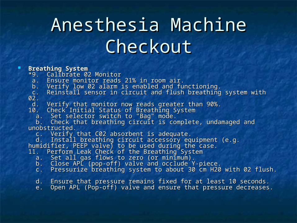
Breathing SystemBreathing System *9. Calibrate 02 Monitor *9. Calibrate 02 Monitor a. Ensure monitor reads 21% in room air. a. Ensure monitor reads 21% in room air. b. Verify low 02 alarm is enabled and functioning. b. Verify low 02 alarm is enabled and functioning. c. Reinstall sensor in circuit and flush breathing system with 02. c. Reinstall sensor in circuit and flush breathing system with 02. d. Verify that monitor now reads greater than 90%. d. Verify that monitor now reads greater than 90%. 10. Check Initial Status of Breathing System 10. Check Initial Status of Breathing System a. Set selector switch to "Bag" mode. a. Set selector switch to "Bag" mode. b. Check that breathing circuit is complete, undamaged and b. Check that breathing circuit is complete, undamaged and unobstructed. unobstructed. c. Verify that C02 absorbent is adequate. c. Verify that C02 absorbent is adequate. d. Install breathing circuit accessory equipment (e.g. humidifier, PEEP d. Install breathing circuit accessory equipment (e.g. humidifier, PEEP valve) to be used during the case. valve) to be used during the case. 11. Perform Leak Check of the Breathing System 11. Perform Leak Check of the Breathing System a. Set all gas flows to zero (or minimum). a. Set all gas flows to zero (or minimum). b. Close APL (pop-off) valve and occlude Y-piece. b. Close APL (pop-off) valve and occlude Y-piece. c. Pressurize breathing system to about 30 cm H20 with 02 flush. c. Pressurize breathing system to about 30 cm H20 with 02 flush. d. Ensure that pressure remains fixed for at least 10 seconds. d. Ensure that pressure remains fixed for at least 10 seconds. e. Open APL (Pop-off) valve and ensure that pressure decreases. e. Open APL (Pop-off) valve and ensure that pressure decreases.
Anesthesia Machine Anesthesia Machine CheckoutCheckout
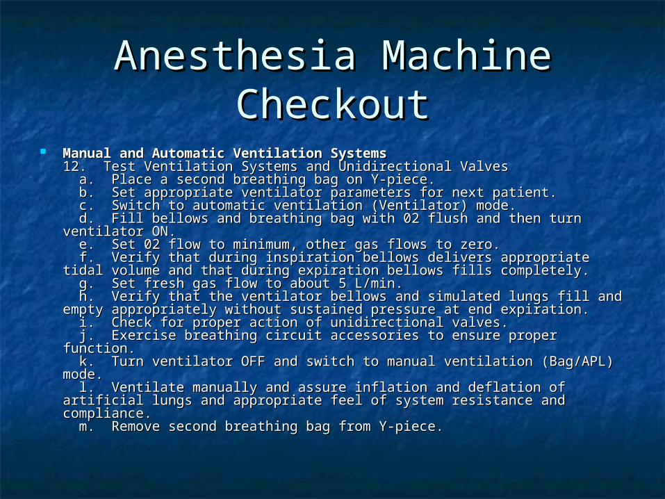
Manual and Automatic Ventilation SystemsManual and Automatic Ventilation Systems 12. Test Ventilation Systems and Unidirectional Valves 12. Test Ventilation Systems and Unidirectional Valves a. Place a second breathing bag on Y-piece. a. Place a second breathing bag on Y-piece. b. Set appropriate ventilator parameters for next patient. b. Set appropriate ventilator parameters for next patient. c. Switch to automatic ventilation (Ventilator) mode. c. Switch to automatic ventilation (Ventilator) mode. d. Fill bellows and breathing bag with 02 flush and then turn ventilator d. Fill bellows and breathing bag with 02 flush and then turn ventilator ON. ON. e. Set 02 flow to minimum, other gas flows to zero. e. Set 02 flow to minimum, other gas flows to zero. f. Verify that during inspiration bellows delivers appropriate tidal volume f. Verify that during inspiration bellows delivers appropriate tidal volume and that during expiration bellows fills completely. and that during expiration bellows fills completely. g. Set fresh gas flow to about 5 L/min. g. Set fresh gas flow to about 5 L/min. h. Verify that the ventilator bellows and simulated lungs fill and empty h. Verify that the ventilator bellows and simulated lungs fill and empty appropriately without sustained pressure at end expiration. appropriately without sustained pressure at end expiration. i. Check for proper action of unidirectional valves. i. Check for proper action of unidirectional valves. j. Exercise breathing circuit accessories to ensure proper function. j. Exercise breathing circuit accessories to ensure proper function. k. Turn ventilator OFF and switch to manual ventilation (Bag/APL) mode. k. Turn ventilator OFF and switch to manual ventilation (Bag/APL) mode. l. Ventilate manually and assure inflation and deflation of artificial lungs l. Ventilate manually and assure inflation and deflation of artificial lungs and appropriate feel of system resistance and compliance. and appropriate feel of system resistance and compliance. m. Remove second breathing bag from Y-piece. m. Remove second breathing bag from Y-piece.
Anesthesia Machine Anesthesia Machine CheckoutCheckout
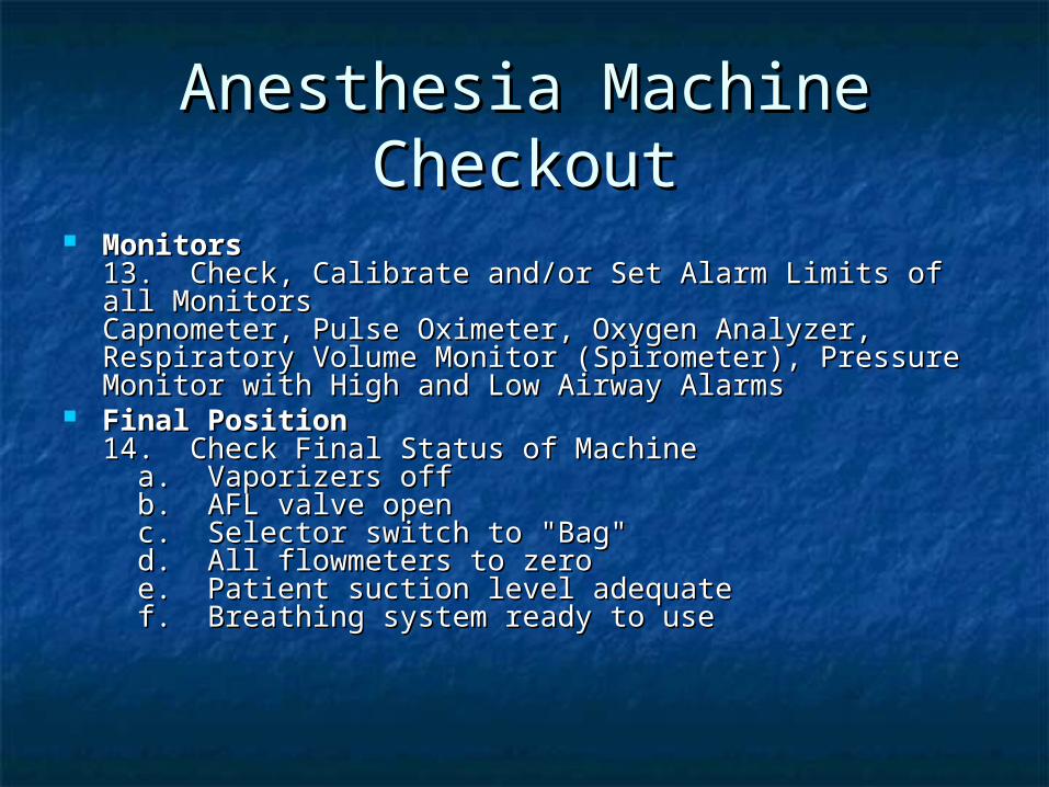
MonitorsMonitors 13. Check, Calibrate and/or Set Alarm Limits of all Monitors 13. Check, Calibrate and/or Set Alarm Limits of all Monitors
Capnometer, Pulse Oximeter, Oxygen Analyzer, Respiratory Capnometer, Pulse Oximeter, Oxygen Analyzer, Respiratory Volume Monitor (Spirometer), Pressure Monitor with High Volume Monitor (Spirometer), Pressure Monitor with High and Low Airway Alarms and Low Airway Alarms
Final PositionFinal Position 14. Check Final Status of Machine 14. Check Final Status of Machine a. Vaporizers off a. Vaporizers off b. AFL valve open b. AFL valve open c. Selector switch to "Bag" c. Selector switch to "Bag" d. All flowmeters to zero d. All flowmeters to zero e. Patient suction level adequate e. Patient suction level adequate f. Breathing system ready to use f. Breathing system ready to use
The Anesthesia MachineThe Anesthesia Machine
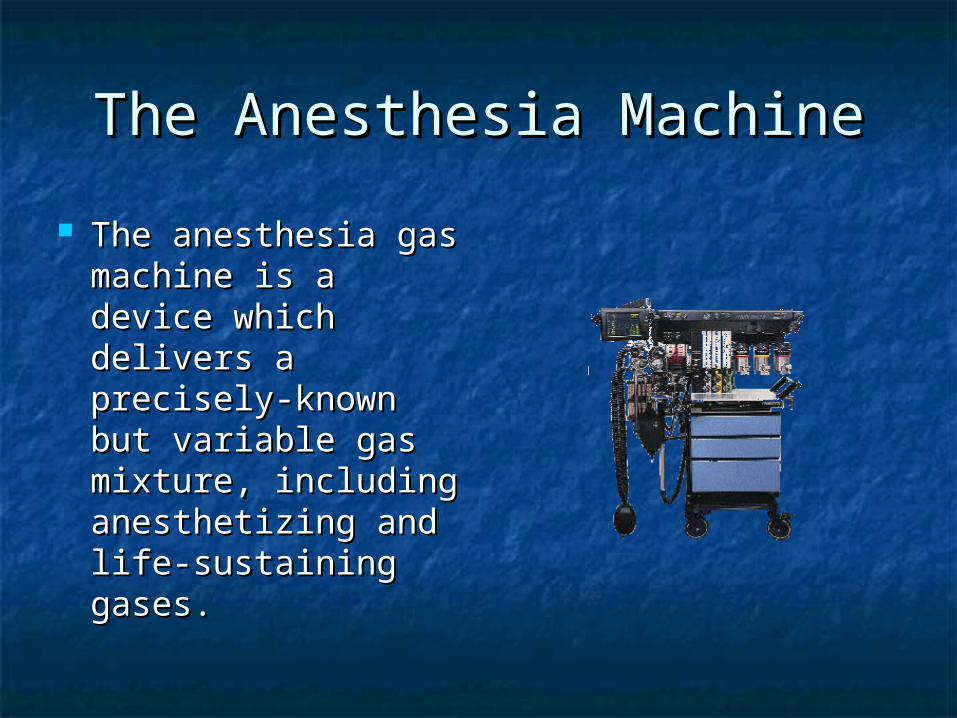
The anesthesia gas The anesthesia gas machine is a device machine is a device which delivers a which delivers a precisely-known but precisely-known but variable gas variable gas mixture, including mixture, including anesthetizing and anesthetizing and life-sustaining life-sustaining gases. gases.
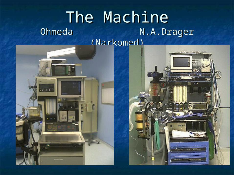
The MachineThe MachineOhmedaOhmeda N.A.Drager (Narkomed) N.A.Drager (Narkomed)
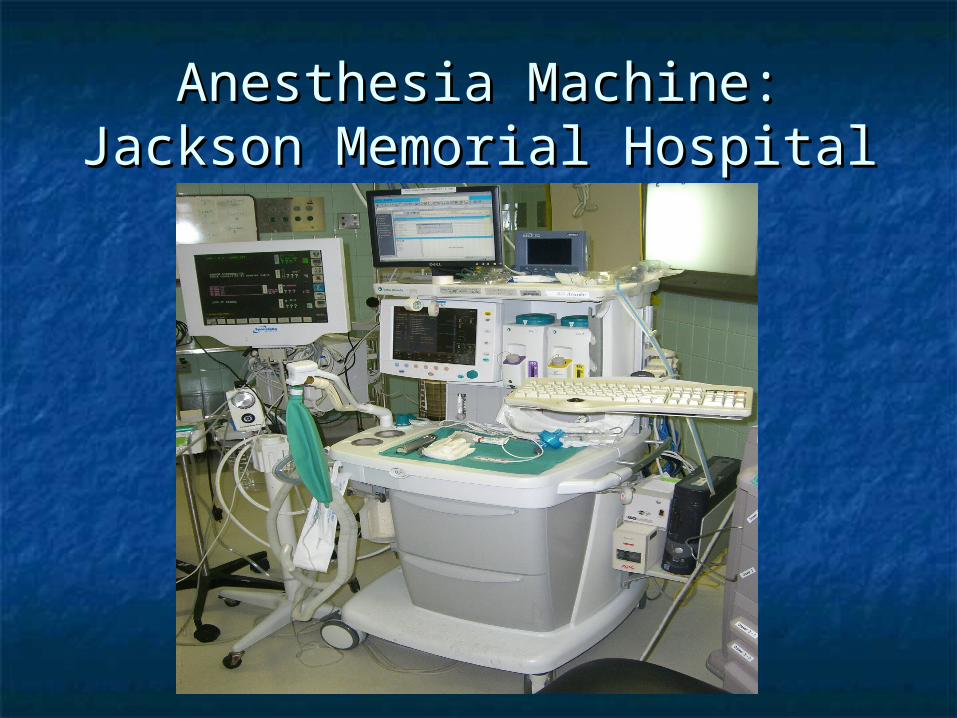
Anesthesia Machine: Anesthesia Machine: Jackson Memorial HospitalJackson Memorial Hospital

Manufacturers & NamesManufacturers & Names
North American North American DrägerDräger (Telford, PA) is (Telford, PA) is the manufacturer of the the manufacturer of the NarkomedNarkomed 2C 2C, , NarkomedNarkomed 4 4, , NarkomedNarkomed GS GS, , NarkomedNarkomed 6000 6000, , NarkomedNarkomed Julian Julian, , NarkomedNarkomed MRI MRI and and NarkomedNarkomed Mobile Mobile models. models.
Datex-Ohmeda (Madison WI) Datex-Ohmeda (Madison WI) manufactures the manufactures the AS/3 ADUAS/3 ADU, , AestivaAestiva, , Modulus SEModulus SE, , Excel 210Excel 210, and Excel 110 , and Excel 110
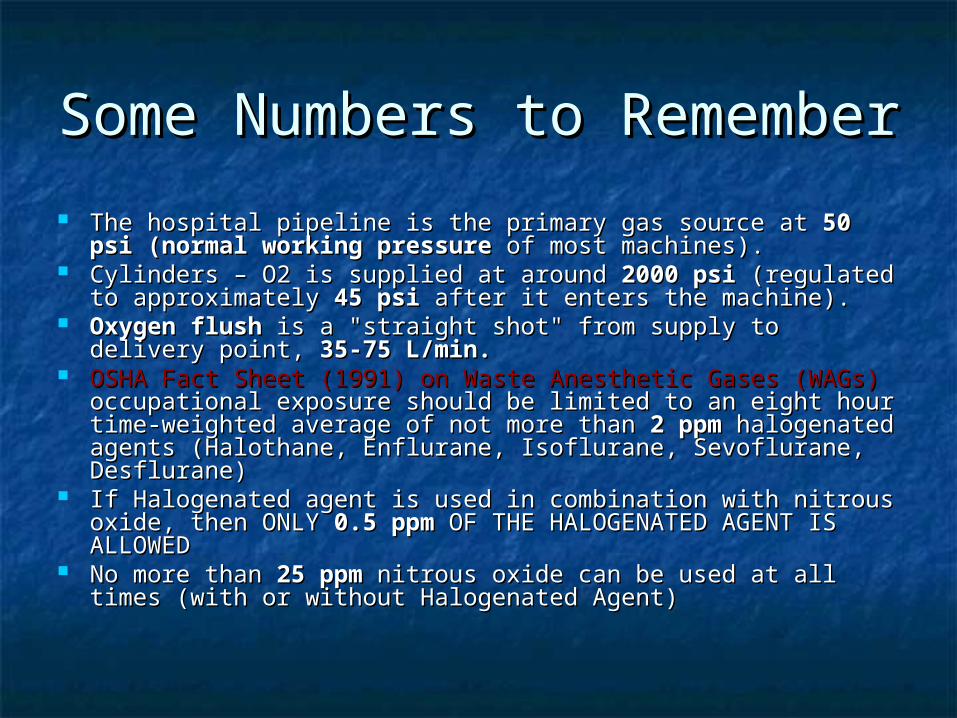
Some Numbers to Some Numbers to RememberRemember
The hospital pipeline is the primary gas source at The hospital pipeline is the primary gas source at 50 psi 50 psi (normal working pressure(normal working pressure of most machines). of most machines).
Cylinders – O2 is supplied at around Cylinders – O2 is supplied at around 2000 psi2000 psi (regulated to (regulated to approximately approximately 45 psi45 psi after it enters the machine). after it enters the machine).
Oxygen flushOxygen flush is a "straight shot" from supply to delivery is a "straight shot" from supply to delivery point, point, 35-75 L/min.35-75 L/min.
OSHA Fact Sheet (1991) on Waste Anesthetic Gases (WAGs)OSHA Fact Sheet (1991) on Waste Anesthetic Gases (WAGs) occupational exposure should be limited to an eight hour occupational exposure should be limited to an eight hour time-weighted average of not more than time-weighted average of not more than 2 ppm2 ppm halogenated halogenated agents (Halothane, Enflurane, Isoflurane, Sevoflurane, agents (Halothane, Enflurane, Isoflurane, Sevoflurane, Desflurane) Desflurane)
If Halogenated agent is used in combination with nitrous If Halogenated agent is used in combination with nitrous oxide, then ONLY oxide, then ONLY 0.5 ppm0.5 ppm OF THE HALOGENATED AGENT IS OF THE HALOGENATED AGENT IS ALLOWEDALLOWED
No more than No more than 25 ppm25 ppm nitrous oxide can be used at all times nitrous oxide can be used at all times (with or without Halogenated Agent) (with or without Halogenated Agent)
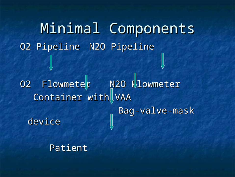
Minimal ComponentsMinimal ComponentsO2 PipelineO2 Pipeline N2O PipelineN2O Pipeline
O2 FlowmeterO2 Flowmeter N2O N2O FlowmeterFlowmeter
Container with VAAContainer with VAA
Bag-valve-mask deviceBag-valve-mask device
PatientPatient

Straight-line model Straight-line model SPDD SPDD
(Supply/Processing/Delivery/Disposal)(Supply/Processing/Delivery/Disposal)
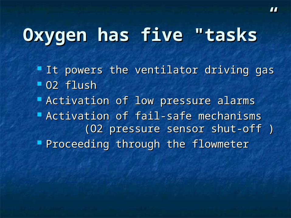
Oxygen has five "tasks”Oxygen has five "tasks”
It powers the ventilator driving gas It powers the ventilator driving gas O2 flush O2 flush Activation of low pressure alarms Activation of low pressure alarms Activation of fail-safe mechanisms Activation of fail-safe mechanisms
(O2 pressure sensor shut-off ) (O2 pressure sensor shut-off ) Proceeding through the flowmeterProceeding through the flowmeter
““Other gases: One task Other gases: One task Only”Only”
Transported via flowmeter & Transported via flowmeter & breathing circuit to:breathing circuit to: Anesthetize pt (N2O)Anesthetize pt (N2O) Sustain Life (Air)Sustain Life (Air)
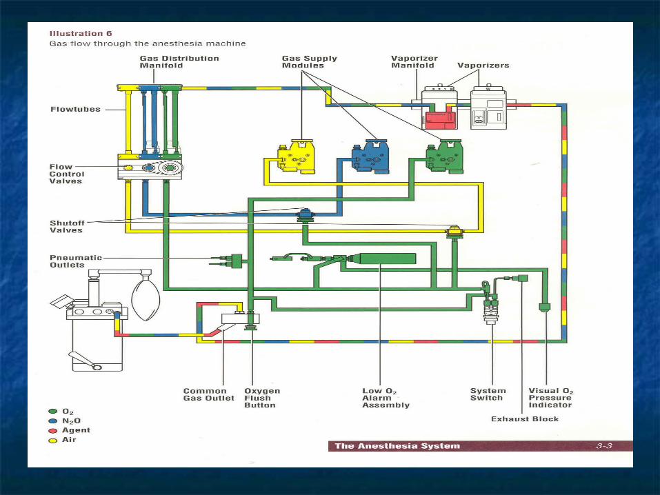
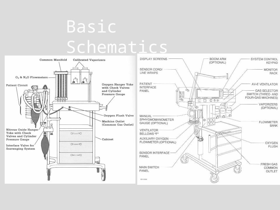
Basic Schematics
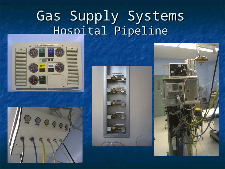
Gas Supply SystemsGas Supply SystemsHospital PipelineHospital Pipeline
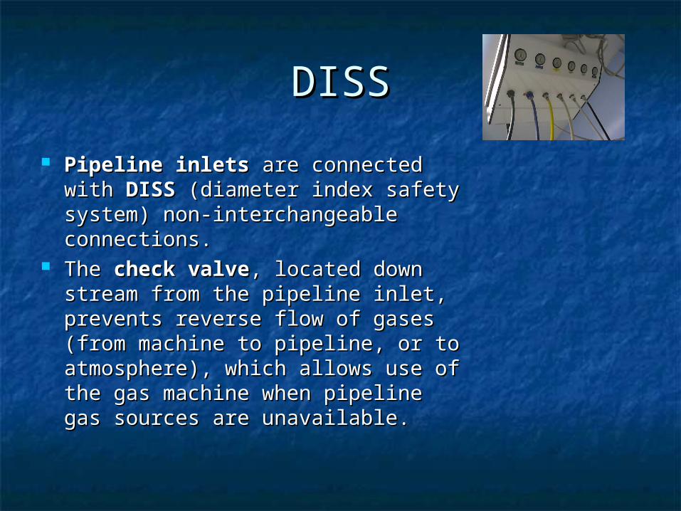
DISSDISS
Pipeline inletsPipeline inlets are connected are connected with with DISSDISS (diameter index safety (diameter index safety system) non-interchangeable system) non-interchangeable connections. connections.
The The check valvecheck valve, located down , located down stream from the pipeline inlet, stream from the pipeline inlet, prevents reverse flow of gases prevents reverse flow of gases (from machine to pipeline, or to (from machine to pipeline, or to atmosphere), which allows use of atmosphere), which allows use of the gas machine when pipeline the gas machine when pipeline gas sources are unavailable. gas sources are unavailable.
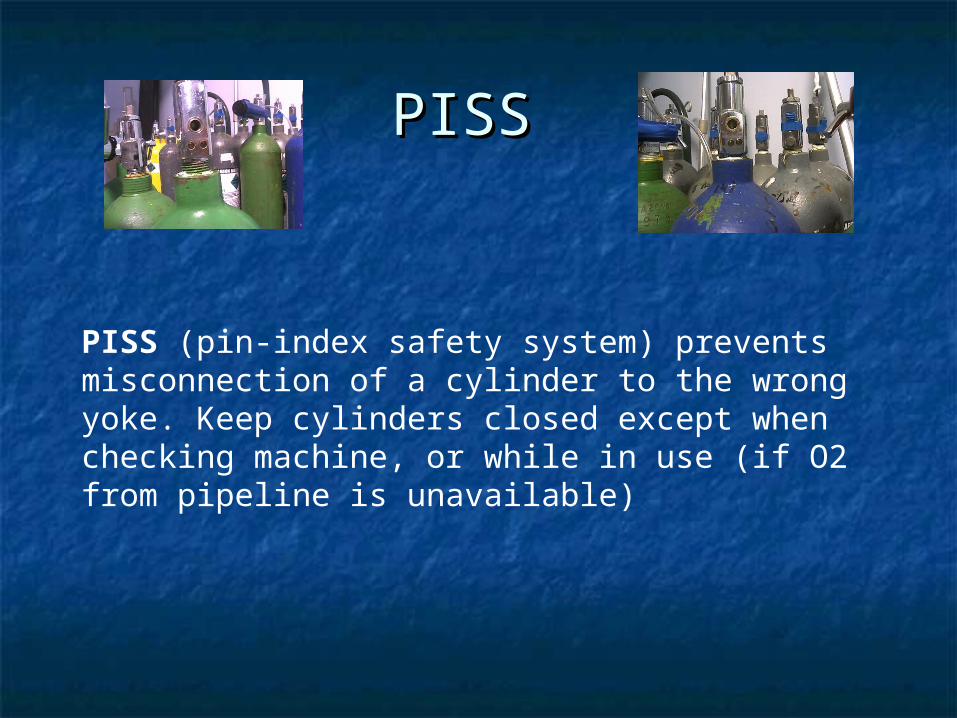
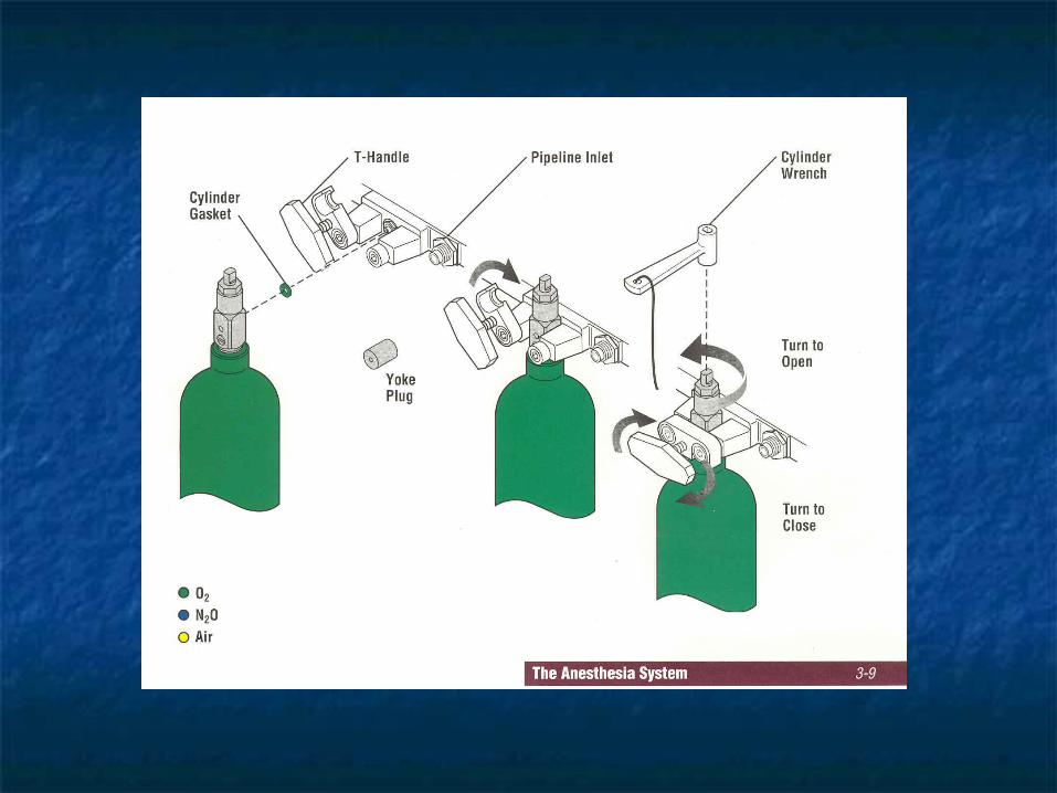
PISS PISS
PISS (pin-index safety system) prevents misconnection of a cylinder to the wrong yoke. Keep cylinders closed except when checking machine, or while in use (if O2 from pipeline is unavailable)
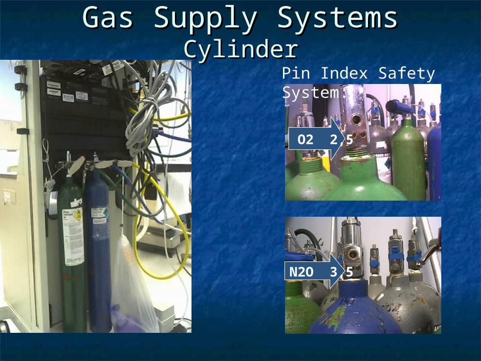
Gas Supply SystemsGas Supply SystemsCylinderCylinder
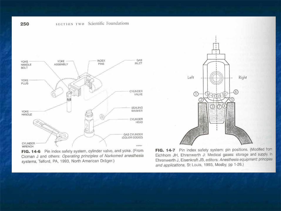
Pin Index Safety System:
O2 2,5
N2O 3,5
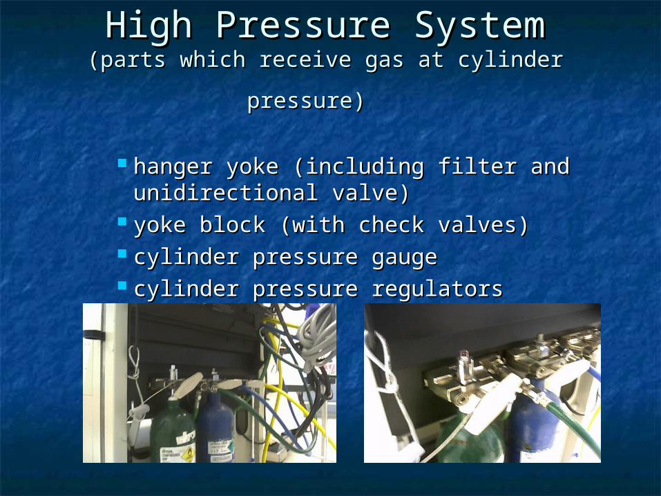
High Pressure SystemHigh Pressure System(parts which receive gas at cylinder pressure)(parts which receive gas at cylinder pressure)
hanger yoke (including filter and hanger yoke (including filter and unidirectional valve) unidirectional valve)
yoke block (with check valves) yoke block (with check valves) cylinder pressure gauge cylinder pressure gauge cylinder pressure regulators cylinder pressure regulators
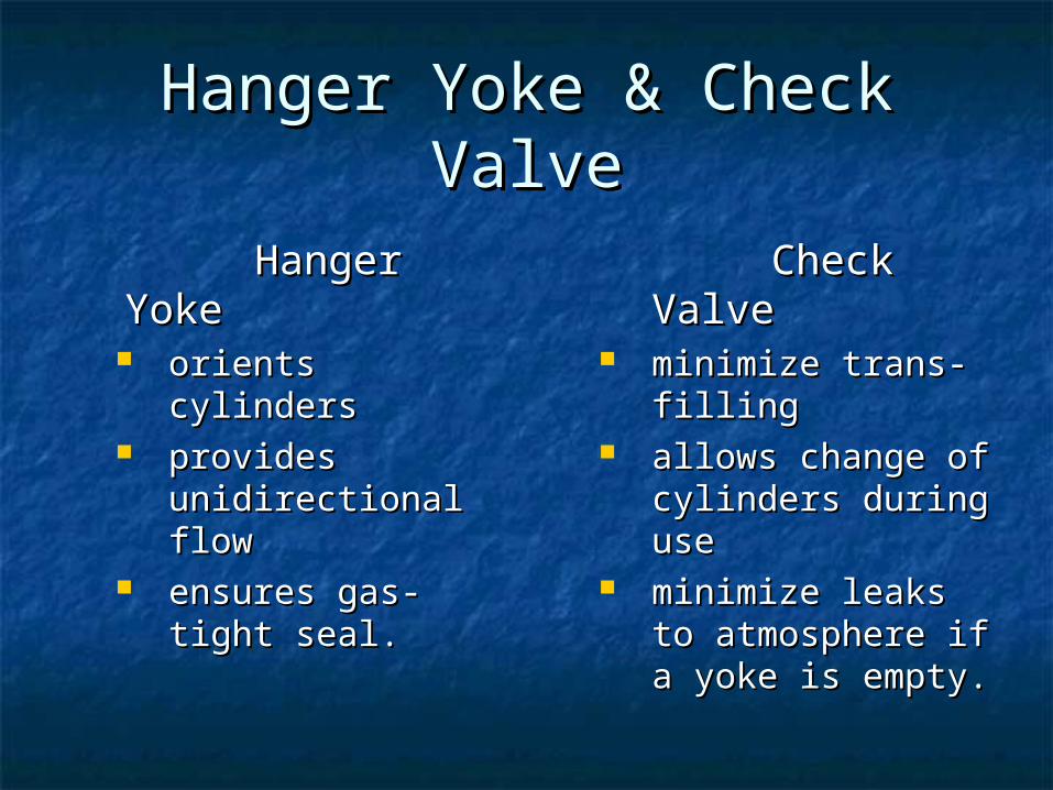
Hanger Yoke & Check ValveHanger Yoke & Check Valve
Hanger YokeHanger Yoke orients cylindersorients cylinders provides provides
unidirectional flow unidirectional flow ensures gas-tight ensures gas-tight
seal. seal.
Check ValveCheck Valve minimize trans-minimize trans-
fillingfilling allows change of allows change of
cylinders during cylinders during useuse
minimize leaks to minimize leaks to atmosphere if a atmosphere if a yoke is empty. yoke is empty.
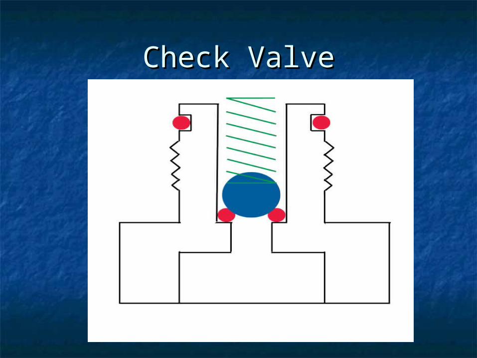
Check ValveCheck Valve
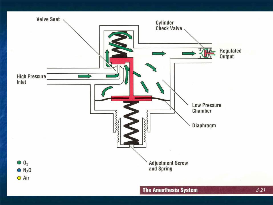
More on CylindersMore on Cylinders
The The cylinder pressure regulatorcylinder pressure regulator converts converts high, variable cylinder pressure to a constant high, variable cylinder pressure to a constant pressure of approximately 45 psi downstream pressure of approximately 45 psi downstream of the regulator.of the regulator.
This is intentionally slightly less than pipeline This is intentionally slightly less than pipeline pressure, to prevent silent depletion of pressure, to prevent silent depletion of cylinder contents if a cylinder is inadvertently cylinder contents if a cylinder is inadvertently left open after checking its pressure. left open after checking its pressure.
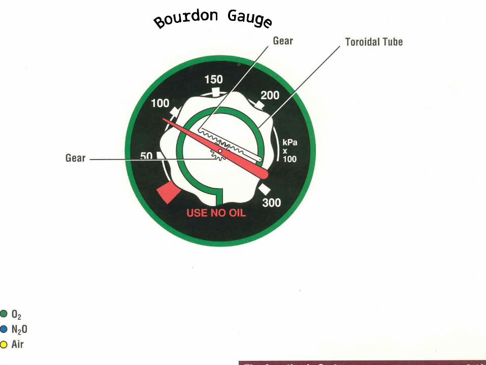
Cylinder pressureCylinder pressure gauge gauge indicates pressure in indicates pressure in the higher-pressure cylinder only (if two are the higher-pressure cylinder only (if two are opened simultaneously). opened simultaneously).
E cylinder CharacteristicsE cylinder Characteristics
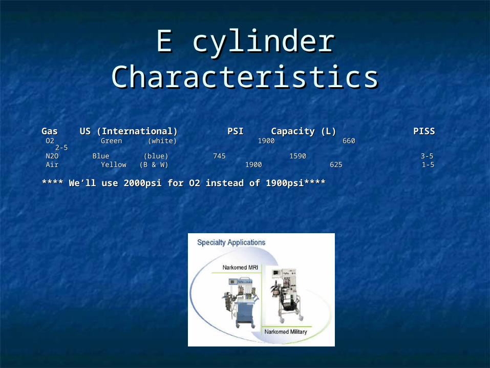
Gas US (International) PSI Capacity (L) PISSGas US (International) PSI Capacity (L) PISS O2 Green (white) 1900 660O2 Green (white) 1900 660 2-5 2-5 N2O Blue (blue) N2O Blue (blue) 745 1590 3-5 745 1590 3-5 Air Yellow (B & W) 1900 625Air Yellow (B & W) 1900 625 1-5 1-5
**** We’ll use 2000psi for O2 instead of 1900psi******** We’ll use 2000psi for O2 instead of 1900psi****
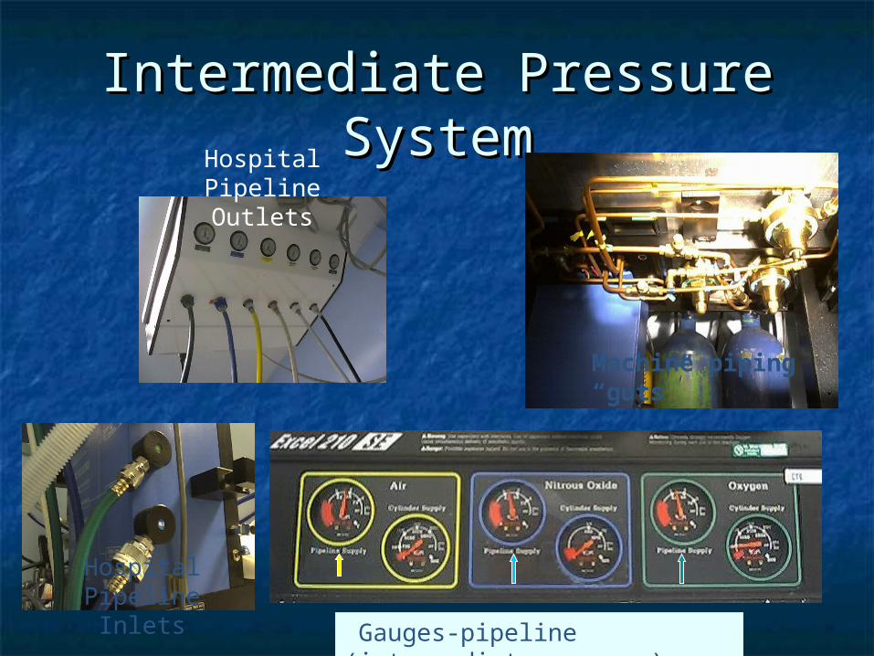
Intermediate Pressure Intermediate Pressure SystemSystem
Machine piping “guts”
Gauges-pipeline (intermediate press. )
Hospital Pipeline Outlets
Hospital Pipeline Inlets
Intermediate Pressure Intermediate Pressure SystemSystem
((receives gases at low, relatively receives gases at low, relatively constant pressures (37-55 psi, = constant pressures (37-55 psi, = pipeline pressure)pipeline pressure)
(*For consistency we’ll use 50 psi) (*For consistency we’ll use 50 psi) pipeline inlets and pressure gauges pipeline inlets and pressure gauges ventilator power inlet ventilator power inlet Oxygen pressure-failure device (fail-Oxygen pressure-failure device (fail-
safe) and alarm safe) and alarm flowmeter valves flowmeter valves oxygen second-stage regulator oxygen second-stage regulator oxygen flush valve oxygen flush valve
Oxygen pressure-failure device Oxygen pressure-failure device
(fail-safe) and alarm(fail-safe) and alarm What happens if you lose oxygen What happens if you lose oxygen
pipeline pressure?pipeline pressure? The The fail safe devicefail safe device ensures that "Whenever oxygen ensures that "Whenever oxygen
pressure is reduced and until flow ceases, the set pressure is reduced and until flow ceases, the set oxygen concentration shall not decrease at the common oxygen concentration shall not decrease at the common gas outlet" (from ASTM F1161). gas outlet" (from ASTM F1161).
The loss of oxygen pressure results in The loss of oxygen pressure results in alarmsalarms, audible , audible
and visible, at 30 psi pipeline pressure.and visible, at 30 psi pipeline pressure. Fail-safe systems don't prevent Fail-safe systems don't prevent
hypoxic mixtures. hypoxic mixtures.
Fail-safe systems Fail-safe systems don'tdon't prevent prevent hypoxic mixtureshypoxic mixtures
as long as there is pressure in the O2 line, as long as there is pressure in the O2 line, nothing in the fail safe system prevents you from nothing in the fail safe system prevents you from turning on a gas mixture of 100% nitrous oxide turning on a gas mixture of 100% nitrous oxide (however, this should be prevented by the (however, this should be prevented by the hypoxic guard system) hypoxic guard system)
or 100% helium (which wouldn’t be prevented by or 100% helium (which wouldn’t be prevented by the hypoxic guard). the hypoxic guard).
Datex-Ohmeda terms their fail safe a "pressure Datex-Ohmeda terms their fail safe a "pressure sensor shut off valve"- at 20 psi oxygen, the flow sensor shut off valve"- at 20 psi oxygen, the flow of all other gases are shut off. Dräger's, "oxygen of all other gases are shut off. Dräger's, "oxygen failure protection device" (OFPD) threshold is failure protection device" (OFPD) threshold is proportional, unlike Ohmeda's which is off-or-on. proportional, unlike Ohmeda's which is off-or-on.
Fail-safe systems Fail-safe systems don'tdon't prevent prevent hypoxic mixtures (Cont…)hypoxic mixtures (Cont…)
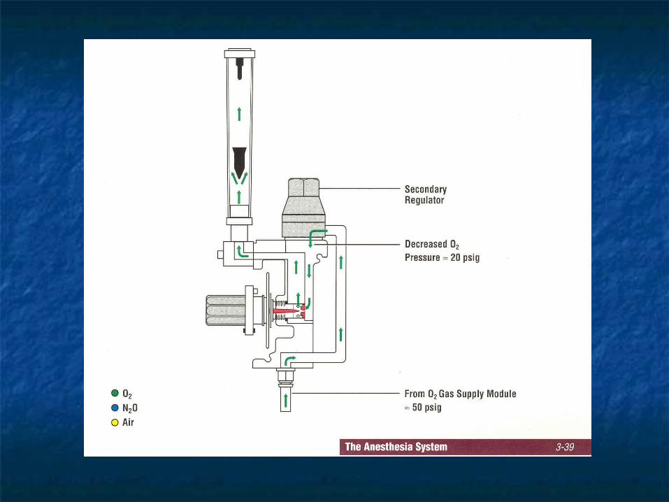
Ohmeda uses a Ohmeda uses a second-stage O2 second-stage O2 pressure regulatorpressure regulator (ensures constant (ensures constant oxygen flowmeter input until supply oxygen flowmeter input until supply pressure is less than 12-16 psi). The pressure is less than 12-16 psi). The oxygen ratio monitor controlleroxygen ratio monitor controller (ORM [newer] or ORMC, both by (ORM [newer] or ORMC, both by Dräger) shuts off nitrous oxide when Dräger) shuts off nitrous oxide when oxygen pressure is less than 10 psi oxygen pressure is less than 10 psi
Pipeline TroublePipeline Trouble
Pipeline sources are Pipeline sources are notnot trouble trouble freefree: contamination (particles, : contamination (particles, bacteria, viral, moisture), inadequate bacteria, viral, moisture), inadequate pressure, excessive pressures, and pressure, excessive pressures, and accidental crossover (switch between accidental crossover (switch between oxygen and some other gas such as oxygen and some other gas such as nitrous oxide or nitrogen) are all nitrous oxide or nitrogen) are all reported. reported.
What if you lose oxygen What if you lose oxygen pipeline pressure?pipeline pressure?
Open the emergency oxygen cylinder fully (not just the Open the emergency oxygen cylinder fully (not just the three or four turns used for checking) three or four turns used for checking)
Disconnect the pipeline connection at the wall Disconnect the pipeline connection at the wall Why? Something is Why? Something is wrongwrong with the oxygen pipeline. with the oxygen pipeline. What if the supply problem evolves into a non-oxygen What if the supply problem evolves into a non-oxygen
gas in the oxygen pipeline? If so, it will flow to the gas in the oxygen pipeline? If so, it will flow to the patient (pipeline pressure 50 psi) rather than your patient (pipeline pressure 50 psi) rather than your oxygen cylinder source (down-regulated to 45 psi). oxygen cylinder source (down-regulated to 45 psi). If you are lucky, the oxygen alarm will sound to warn If you are lucky, the oxygen alarm will sound to warn
you of the change (you do set your alarms, don't you of the change (you do set your alarms, don't you?). you?).
If for some reason the oxygen analyzer does not If for some reason the oxygen analyzer does not warn of the crossover, the pulse oximeter will- but warn of the crossover, the pulse oximeter will- but only only afterafter the oxygen has been washed out by the oxygen has been washed out by ventilation from the patient's functional residual ventilation from the patient's functional residual capacity and vessel-rich group. capacity and vessel-rich group.
Reinforcement!!!!Reinforcement!!!!
Disconnect the pipeline connection at the wall Disconnect the pipeline connection at the wall if oxygen pipeline pressure is lost. It's also if oxygen pipeline pressure is lost. It's also easier to remember one strategy which works easier to remember one strategy which works for any problem with the pipeline, rather than for any problem with the pipeline, rather than to remember that sometimes you must, and to remember that sometimes you must, and sometimes it is optional, to disconnect. And sometimes it is optional, to disconnect. And use that oxygen analyzer always! use that oxygen analyzer always!
Ventilate by hand rather than with the Ventilate by hand rather than with the mechanical ventilator (which uses cylinder mechanical ventilator (which uses cylinder oxygen for the driving gas if the pipeline is oxygen for the driving gas if the pipeline is unavailable) unavailable)
HOW LONG BEFORE HOW LONG BEFORE O2 TANK IS EXHAUSTED???O2 TANK IS EXHAUSTED???-The time to exhaustion is calculated by dividing -The time to exhaustion is calculated by dividing the remaining O2 volume in the cylinder by the the remaining O2 volume in the cylinder by the rate of consumption of O2. rate of consumption of O2.
-Remaining volume in liters (L) in an E-cylinder -Remaining volume in liters (L) in an E-cylinder is calculated by dividing the cylinder pressure in is calculated by dividing the cylinder pressure in psig by 2000 psig and multiplying by 660 L. psig by 2000 psig and multiplying by 660 L.
EXAMPLEEXAMPLE
If cylinder gauge reads 1,000 psig, this represents If cylinder gauge reads 1,000 psig, this represents (1000/2000) X 660 = 330 L left in that tank. The rate of (1000/2000) X 660 = 330 L left in that tank. The rate of consumption of O2 during consumption of O2 during mechanical ventilationmechanical ventilation is the is the sum of the O2 flow meter setting and the patient’s minute sum of the O2 flow meter setting and the patient’s minute ventilation ventilation (VT in L x RR in breaths/min).(VT in L x RR in breaths/min).
If FGF is If FGF is 0.5 L/min O20.5 L/min O2 and 1.0 L/min N2O and VT is 0.7 L and 1.0 L/min N2O and VT is 0.7 L and RR is 10 bpm, then the minute ventilation is and RR is 10 bpm, then the minute ventilation is 7 L/min (0.7L x 10 bpm) 7 L/min (0.7L x 10 bpm)
** The total O2 consumption is The total O2 consumption is 7.5 L/min7.5 L/min. The expected time . The expected time to exhaustion is thus approximately 330 L divided by 7.5 to exhaustion is thus approximately 330 L divided by 7.5 L/min = 44 min (ignoring the gas sampled by the gas L/min = 44 min (ignoring the gas sampled by the gas analyzer and leaksanalyzer and leaks))
The The Low-pressure systemLow-pressure system((distal to flowmeter needle valve)distal to flowmeter needle valve)
flowmeter tubes flowmeter tubes vaporizers vaporizers check valves (if present) check valves (if present) common gas outlet common gas outlet
Flowmeters Flowmeters
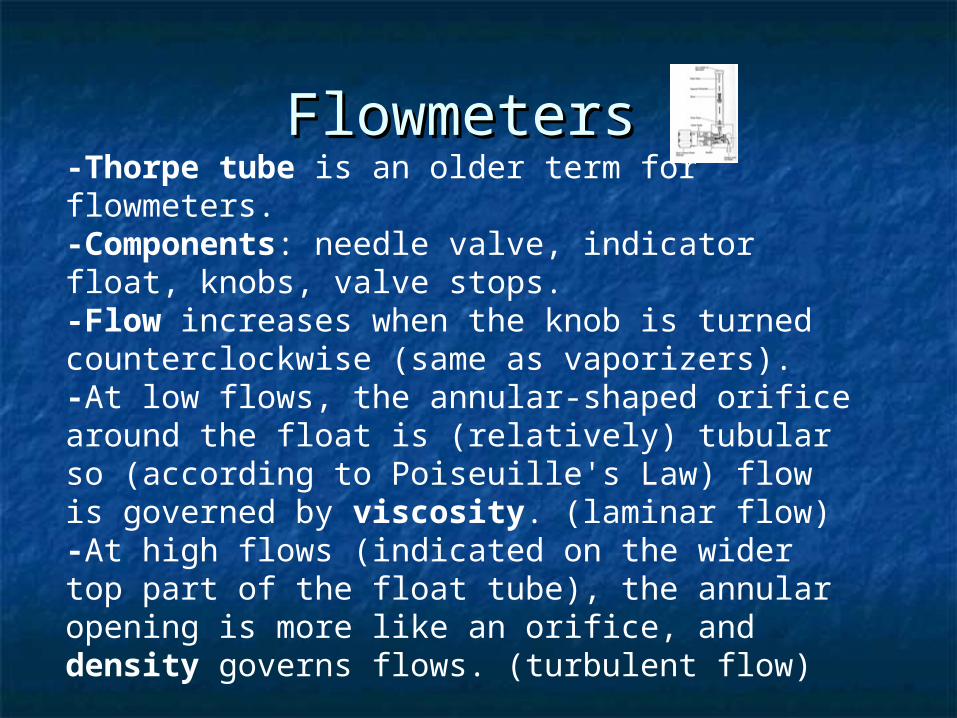
-Thorpe tube is an older term for flowmeters. -Components: needle valve, indicator float, knobs, valve stops. -Flow increases when the knob is turned counterclockwise (same as vaporizers). -At low flows, the annular-shaped orifice around the float is (relatively) tubular so (according to Poiseuille's Law) flow is governed by viscosity. (laminar flow)-At high flows (indicated on the wider top part of the float tube), the annular opening is more like an orifice, and density governs flows. (turbulent flow)
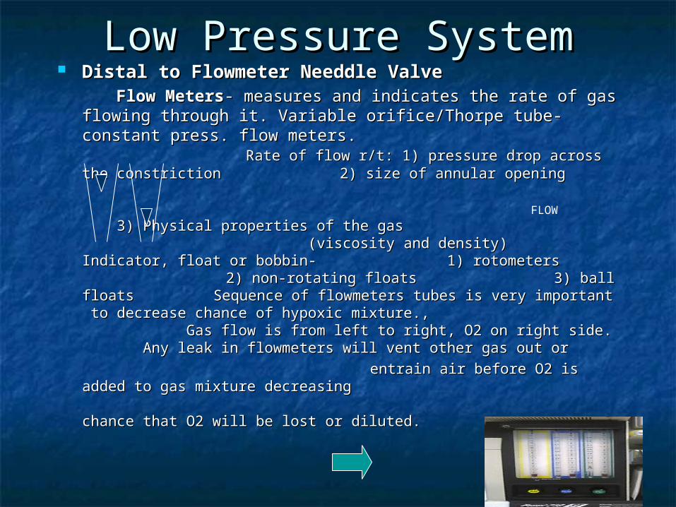
Low Pressure SystemLow Pressure System Distal to Flowmeter Needdle ValveDistal to Flowmeter Needdle Valve Flow MetersFlow Meters- measures and indicates the rate of gas flowing - measures and indicates the rate of gas flowing
through it. Variable orifice/Thorpe tube-constant press. flow through it. Variable orifice/Thorpe tube-constant press. flow meters. meters. Rate of flow r/t: 1) pressure Rate of flow r/t: 1) pressure drop across the constriction drop across the constriction 2) 2) size of annular opening size of annular opening 3) Physical properties of the gas 3) Physical properties of the gas (viscosity and (viscosity and density) density)
Indicator, float or bobbin- 1) Indicator, float or bobbin- 1)
rotometers rotometers 2) non-rotating floats 2) non-rotating floats 3) ball floats 3) ball floats Sequence of Sequence of flowmeters tubes is very importantflowmeters tubes is very important to to decrease chance of hypoxic mixture., decrease chance of hypoxic mixture., Gas Gas flow is from left to right, O2 on right side. flow is from left to right, O2 on right side. Any Any leak in flowmeters will vent other gas out or leak in flowmeters will vent other gas out or
entrain air before O2 is added to gas mixture entrain air before O2 is added to gas mixture decreasing decreasing chance that O2 will be lost or diluted.chance that O2 will be lost or diluted.
FLOW
More on FlowmetersMore on Flowmeters
Needle valve can be damaged if it is Needle valve can be damaged if it is closed with forceclosed with force
Flowtube (Thorpe tube) is tapered Flowtube (Thorpe tube) is tapered (narrower at bottom) and gas-(narrower at bottom) and gas-specificspecific
If gas has 2 tubes, they are If gas has 2 tubes, they are connected in series with a single connected in series with a single control valvecontrol valve
Did anyone say Did anyone say Flowmeters??Flowmeters??
Care of flowmetersCare of flowmeters includes ensuring that: includes ensuring that: floats spin freelyfloats spin freely qualified service personnel regularly maintain gas qualified service personnel regularly maintain gas
machines machines an O2 analyzer used an O2 analyzer used alwaysalways (of course, the readings (of course, the readings
are erroneous during use of nasal cannula) are erroneous during use of nasal cannula) one never adjusts a flowmeter without looking at it one never adjusts a flowmeter without looking at it one includes flowmeters in visual monitoring sweepsone includes flowmeters in visual monitoring sweeps one turns flowmeters off before opening cylinders, one turns flowmeters off before opening cylinders,
connecting pipelines, or turning machine "on". connecting pipelines, or turning machine "on".
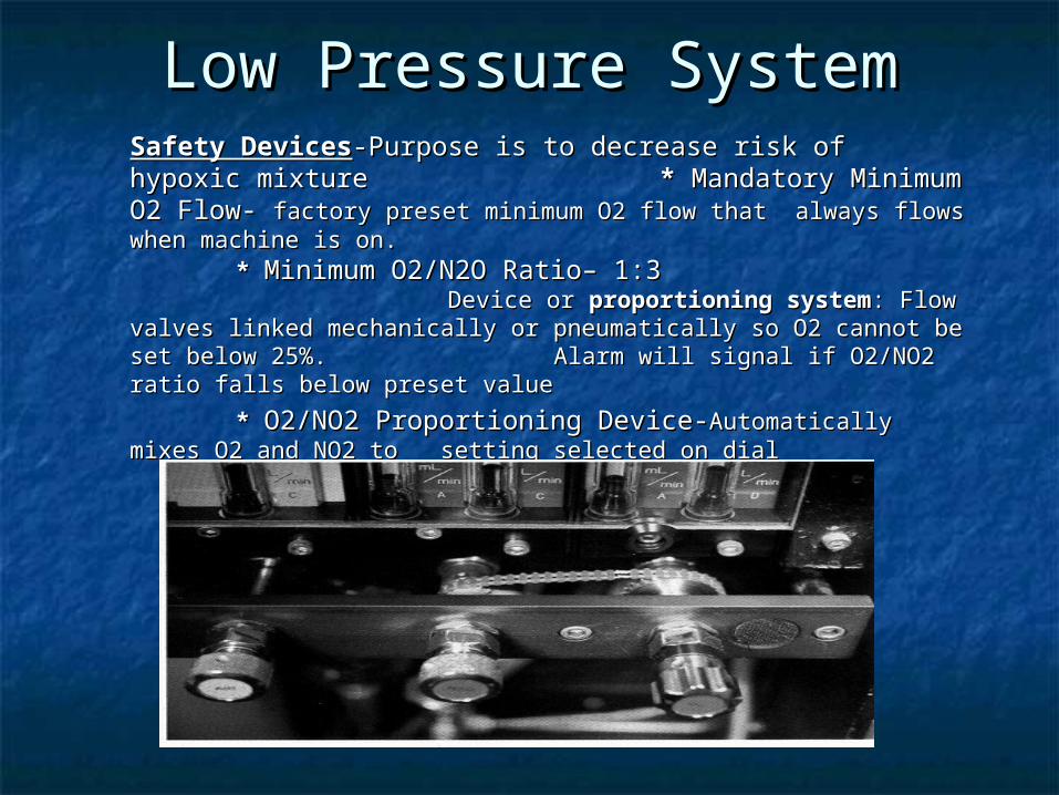
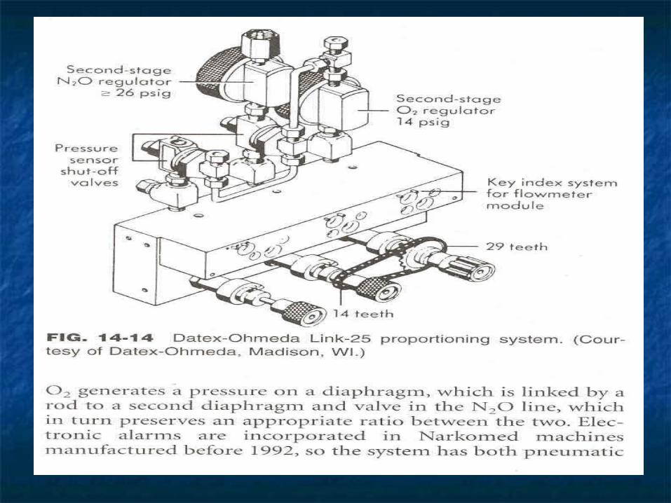
Low Pressure SystemLow Pressure SystemSafety DevicesSafety Devices-Purpose is to decrease risk of hypoxic -Purpose is to decrease risk of hypoxic mixturemixture ** Mandatory Minimum O2 Flow- Mandatory Minimum O2 Flow- factory factory preset minimum O2 flow that always flows when machine is on.preset minimum O2 flow that always flows when machine is on.
* * Minimum Minimum O2/N2O Ratio– 1:3O2/N2O Ratio– 1:3 Device Device or or proportioning systemproportioning system: Flow valves linked mechanically or : Flow valves linked mechanically or pneumatically so O2 cannot be set below 25%.pneumatically so O2 cannot be set below 25%.
Alarm will signal if O2/NO2 ratio falls below preset valueAlarm will signal if O2/NO2 ratio falls below preset value
* * O2/NO2 Proportioning Device-O2/NO2 Proportioning Device-Automatically mixes O2 Automatically mixes O2 and NO2 to setting selected on dialand NO2 to setting selected on dial
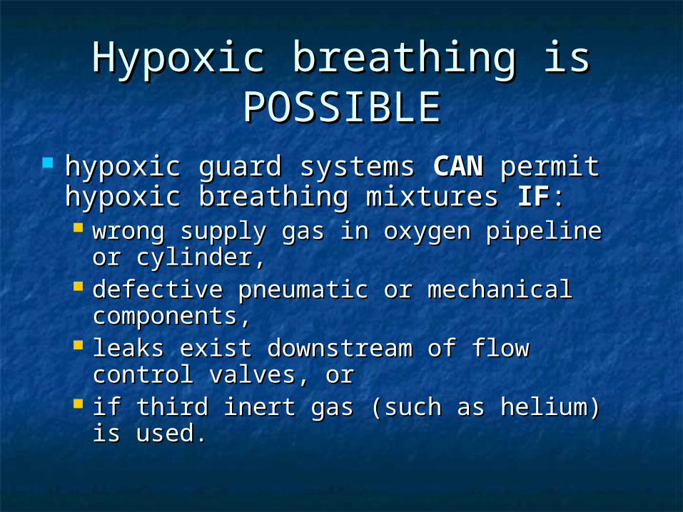
Hypoxic breathing is Hypoxic breathing is POSSIBLEPOSSIBLE
hypoxic guard systems hypoxic guard systems CANCAN permit permit hypoxic breathing mixtureshypoxic breathing mixtures IF IF: : wrong supply gas in oxygen pipeline or wrong supply gas in oxygen pipeline or
cylinder, cylinder, defective pneumatic or mechanical defective pneumatic or mechanical
components, components, leaks exist downstream of flow control leaks exist downstream of flow control
valves, or valves, or if third inert gas (such as helium) is used. if third inert gas (such as helium) is used.
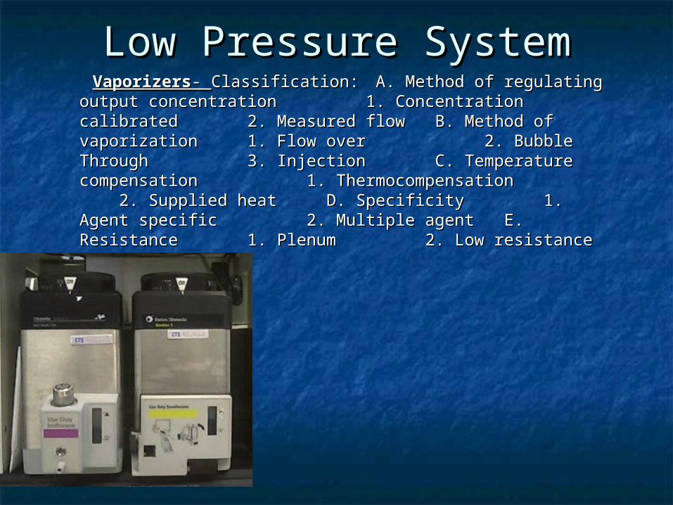
Low Pressure SystemLow Pressure System VaporizersVaporizers- - Classification:Classification:
A. Method of regulating output concentrationA. Method of regulating output concentration 1. Concentration calibrated 1. Concentration calibrated
2. Measured flow 2. Measured flowB. Method of vaporizationB. Method of vaporization
1. Flow over 1. Flow over 2. Bubble Through 2. Bubble Through
3. Injection 3. Injection C. C.
Temperature compensation Temperature compensation 1. Thermocompensation 1. Thermocompensation 2. Supplied heat 2. Supplied heat D. Specificity D. Specificity 1. Agent specific 1. Agent specific 2. Multiple agent 2. Multiple agent E. Resistance E. Resistance 1. Plenum 1. Plenum 2. Low resistance 2. Low resistance
VAPORIZERSVAPORIZERS
Vapor Pressure (VP) Vapor Pressure (VP) Molecules escape Molecules escape from a volatile liquid to the vapor phase, from a volatile liquid to the vapor phase, creating a “saturated vapor pressure” at creating a “saturated vapor pressure” at equilibriumequilibrium
VP is independent of Atmospheric PressVP is independent of Atmospheric Press VP increases with TemperatureVP increases with Temperature VP depends ONLY on the Physical VP depends ONLY on the Physical
Characteristics of the Liquid & on its Characteristics of the Liquid & on its TemperatureTemperature
CLASSIFICATIONCLASSIFICATION
Variable bypassVariable bypass Fresh gas flow from the flowmeters Fresh gas flow from the flowmeters enters the inlet of any vaporizer which is enters the inlet of any vaporizer which is on. The concentration control dial on. The concentration control dial setting splits this stream into bypass gas setting splits this stream into bypass gas (which does not enter the vaporizing (which does not enter the vaporizing chamber), and carrier gas (also called chamber), and carrier gas (also called chamber flow, which flows over the chamber flow, which flows over the liquid agent)liquid agent)
CLASSIFICATIONCLASSIFICATION
Flow overFlow over Carrier gas flows over the surface of the Carrier gas flows over the surface of the liquid volatile agent in the vaporizing liquid volatile agent in the vaporizing chamber (as opposed to bubbling up chamber (as opposed to bubbling up through it (as in the copper kettle and through it (as in the copper kettle and Vernitrol) Vernitrol)
CLASSIFICATIONCLASSIFICATION
Temperature compensatedTemperature compensated Equipped with automatic devices that ensure steady Equipped with automatic devices that ensure steady vaporizer output over a wide range of ambient vaporizer output over a wide range of ambient temperatures temperatures
Agent-specificAgent-specific Only calibrated for a single gas, usually with keyed Only calibrated for a single gas, usually with keyed fillers that decrease the likelihood of filling the fillers that decrease the likelihood of filling the vaporizer with the wrong agent vaporizer with the wrong agent
Out of circuitOut of circuit As opposed to (much) older models such as the As opposed to (much) older models such as the
Ohio #8 (Boyle's bottle) which were inserted within Ohio #8 (Boyle's bottle) which were inserted within the circle system. the circle system.
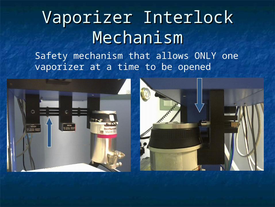
Vaporizer Interlock Vaporizer Interlock MechanismMechanism
Safety mechanism that allows ONLY one vaporizer at a time to be opened
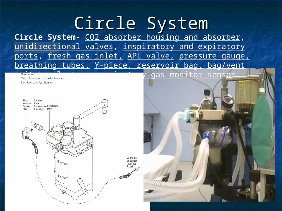
Circle SystemCircle SystemCircle System- CO2 absorber housing and absorber, unidirectional valves, inspiratory and expiratory ports, fresh gas inlet, APL valve, pressure gauge, breathing tubes, Y-piece, reservoir bag, bag/vent switch selector, respiratory gas monitor sensor.
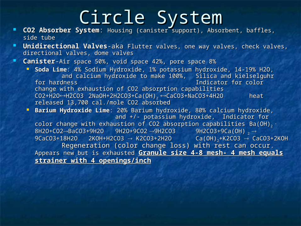
Circle SystemCircle System CO2 Absorber SystemCO2 Absorber System: : Housing (canister support), Absorbent, baffles, side Housing (canister support), Absorbent, baffles, side
tubetube Unidirectional ValvesUnidirectional Valves-aka -aka Flutter valves, one way valves, check valves, Flutter valves, one way valves, check valves,
directional valves, dome valvesdirectional valves, dome valves CanisterCanister--Air space 50%, void space 42%, pore space 8%Air space 50%, void space 42%, pore space 8%
Soda LimeSoda Lime: 4% Sodium Hydroxide, 1% potassium hydroxide, 14-19% H2O, : 4% Sodium Hydroxide, 1% potassium hydroxide, 14-19% H2O, and calcium hydroxide to make 100%, and calcium hydroxide to make 100%,
Silica and kielselguhr for hardnessSilica and kielselguhr for hardness Indicator for color change with exhaustion of CO2 Indicator for color change with exhaustion of CO2 absorption capabilitiesabsorption capabilities CO2+H2OCO2+H2OH2CO3H2CO3
2NaOH+2H2CO3+Ca(OH)2NaOH+2H2CO3+Ca(OH)2 2
CaCO3+NaCO3+4H2OCaCO3+NaCO3+4H2O heat released 13,700 heat released 13,700 cal./mole CO2 absorbedcal./mole CO2 absorbed
Barium Hydroxide LimeBarium Hydroxide Lime: 20% Barium hydroxide, 80% calcium hydroxide, : 20% Barium hydroxide, 80% calcium hydroxide, and +/- potassium hydroxide,and +/- potassium hydroxide, Indicator for color change Indicator for color change with exhaustion of CO2 absorption capabilitieswith exhaustion of CO2 absorption capabilities Ba(OH)Ba(OH)22
. .
8H2O+CO28H2O+CO2BaCO3+9H2OBaCO3+9H2O 9H2O+9CO29H2O+9CO2 9H2CO39H2CO39H2CO3+9Ca(OH)9H2CO3+9Ca(OH) 2 2
9CaCO3+18H2O9CaCO3+18H2O 2KOH+H2CO3 2KOH+H2CO3 K2CO3+2H2OK2CO3+2H2O Ca(OH)Ca(OH)22+K2CO3 +K2CO3 CaCO3+2KOHCaCO3+2KOH Regeneration (color change Regeneration (color change loss) with rest can occur. loss) with rest can occur. Appears new but is exhaustedAppears new but is exhausted Granule size 4-8 Granule size 4-8 mesh- 4 mesh equals strainer with 4 openings/inchmesh- 4 mesh equals strainer with 4 openings/inch
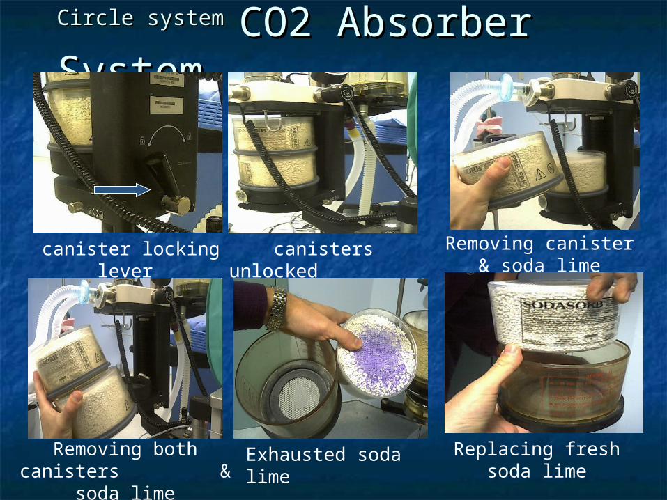
Circle systemCircle system CO2 Absorber CO2 Absorber SystemSystem
canisters unlocked
Removing both canisters & soda lime
canister locking lever Removing canister & soda lime
Exhausted soda lime Replacing fresh soda lime
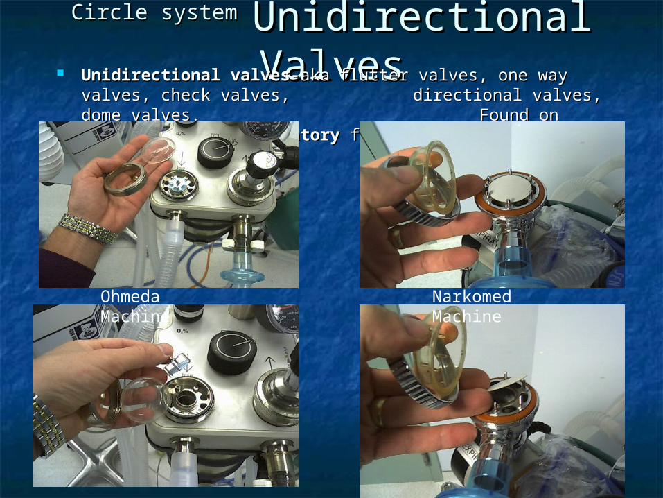
Circle systemCircle system Unidirectional Unidirectional ValvesValves Unidirectional valves-Unidirectional valves-akaaka flutter valves, one way valves, flutter valves, one way valves,
check valves, check valves, directional valves, dome valves.directional valves, dome valves.Found on Found on InspiratoryInspiratory
andand ExpiratoryExpiratory flow ports flow ports
Narkomed MachineOhmeda Machine
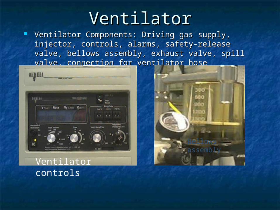
VentilatorVentilator Ventilator Components: Driving gas supply, injector, Ventilator Components: Driving gas supply, injector,
controls, alarms, safety-release valve, bellows controls, alarms, safety-release valve, bellows assembly, exhaust valve, spill valve, connection for assembly, exhaust valve, spill valve, connection for ventilator hoseventilator hose
Bellows assembly
Ventilator controls
VentilatorVentilator Driving gas supply or power gas supply-Driving gas supply or power gas supply-O2 pneumatically drives O2 pneumatically drives
(compresses) ventilator bellows(compresses) ventilator bellows Injector or Venturi mechanism-Injector or Venturi mechanism-Increases the flow of driving gas by using Increases the flow of driving gas by using
the BERNOULLI Principle- As a gas flow meets a restriction, its lateral the BERNOULLI Principle- As a gas flow meets a restriction, its lateral pressure drops. Any opening in the tube at this constriction will entrain air pressure drops. Any opening in the tube at this constriction will entrain air (suck air in)(suck air in)
Controls-Controls-Adjusts Flow, Volume, Timing, and Pressure of the driving gas that Adjusts Flow, Volume, Timing, and Pressure of the driving gas that compresses the bellowscompresses the bellows
PneumaticPneumatic-Uses pressure changes to initiate changes in respiratory -Uses pressure changes to initiate changes in respiratory cyclecycle Fluidic or fluid logicFluidic or fluid logic-Uses gas streams through channels in -Uses gas streams through channels in solid material. Allow solid material. Allow for compact ventilatorfor compact ventilator
ElectronicElectronic-Electronic control of many -Electronic control of many addition ventilation parameters powered addition ventilation parameters powered by a driving gas on newer by a driving gas on newer machines. Must have both power and pnuematics.machines. Must have both power and pnuematics.
Alarms-Alarms-ASTMASTM s standards group alarms into three levels: High, Medium, Low tandards group alarms into three levels: High, Medium, Low Priority Priority correlates to;operator immediate action, prompt action,or correlates to;operator immediate action, prompt action,or awareness. awareness. Loss of main power is the only required alarm Loss of main power is the only required alarm with a required duration of at least with a required duration of at least 2 minutes2 minutes
Safety relief valve-aka Safety relief valve-aka pressure limiting valve, drving gas pressure relief pressure limiting valve, drving gas pressure relief valve. Vents valve. Vents driving gas if factory pre-set pressure is reached (65-80 driving gas if factory pre-set pressure is reached (65-80 cm H2O) or adjustable cm H2O) or adjustable set pressure is reached.set pressure is reached.
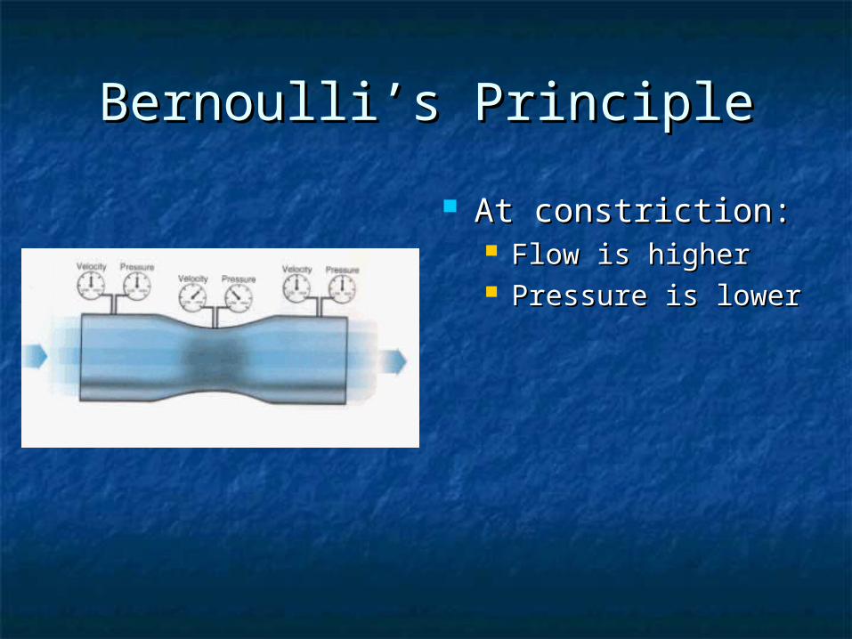
Bernoulli’s PrincipleBernoulli’s Principle
At constriction:At constriction: Flow is higherFlow is higher Pressure is lowerPressure is lower
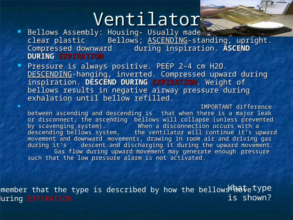
VentilatorVentilator Bellows Assembly:Bellows Assembly: Housing- Usually made of Housing- Usually made of
hard rigid clear plastichard rigid clear plastic Bellows; Bellows; ASCENDINGASCENDING--standing, upright. Compressed downward standing, upright. Compressed downward during inspiration. during inspiration. ASCEND DURING ASCEND DURING EXPIRATIONEXPIRATION
Pressure is always positive. PEEP 2-4 cm H2O.Pressure is always positive. PEEP 2-4 cm H2O.DESCENDINGDESCENDING-hanging, inverted. Compressed upward -hanging, inverted. Compressed upward
during inspiration. during inspiration. DESCEND DURING DESCEND DURING EXPIRATIONEXPIRATION. Weight . Weight of bellows results in negative airway pressure during of bellows results in negative airway pressure during exhalation until bellow refilled.exhalation until bellow refilled.
IMPORTANT difference between ascending and descending is IMPORTANT difference between ascending and descending is
that when there is a major leak or disconnect, the ascending that when there is a major leak or disconnect, the ascending bellows will collapse (unless prevented by scavenging bellows will collapse (unless prevented by scavenging
system). system). When a disconnection occurs with a When a disconnection occurs with a descending bellows system, descending bellows system, the ventilator will continue it’s the ventilator will continue it’s upward movement and downward upward movement and downward movements, drawing in room air movements, drawing in room air and driving gas during it’s and driving gas during it’s descent and discharging it during descent and discharging it during the upward movement. the upward movement. Gas flow during upward Gas flow during upward movement may generate enough movement may generate enough pressure such that the low pressure such that the low pressure alarm is not activated. pressure alarm is not activated.
Remember that the type is described by how the bellows move during EXPIRATION
What type is shown?
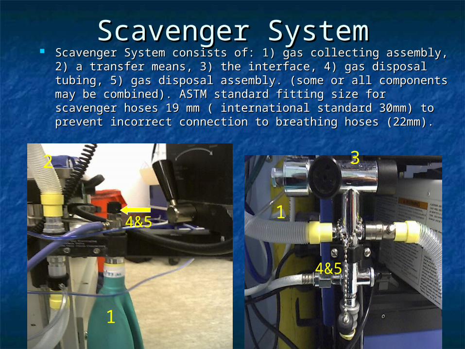
Scavenger SystemScavenger System Scavenger System consists of: Scavenger System consists of: 11) gas collecting assembly, 2) a ) gas collecting assembly, 2) a
transfer means, 3) the interface, 4) gas disposal tubing, 5) gas transfer means, 3) the interface, 4) gas disposal tubing, 5) gas disposal assembly. (some or all components may be combined).disposal assembly. (some or all components may be combined).
ASTM standard fitting ASTM standard fitting size for scavenger hoses 19 mm ( international standard 30mm) size for scavenger hoses 19 mm ( international standard 30mm) to prevent incorrect connection to breathing hoses (22mm).to prevent incorrect connection to breathing hoses (22mm).
1
32
1
4&5
4&5

REFERENCESREFERENCES
N&Z pg 247-252N&Z pg 247-252 M&M pg 35-49M&M pg 35-49 D&D pg 3-74D&D pg 3-74 http://chico.med.yale.edu/machine/ahttp://chico.med.yale.edu/machine/a
gmpart1.htm#General%20featuresgmpart1.htm#General%20features http://www.anest.ufl.edu/~eduweb/http://www.anest.ufl.edu/~eduweb/
vam/vam/

UnknownUnknown The essence of intelligence is skill in extracting The essence of intelligence is skill in extracting
meaning from everyday experience meaning from everyday experience