Embed Size (px)
Citation preview

ANDROID DRO PRESENTED BY RICHARD DOUGLAS
DESIGENED BT YURI KRUSHELNYTSKIY
YURISTOYS.COM
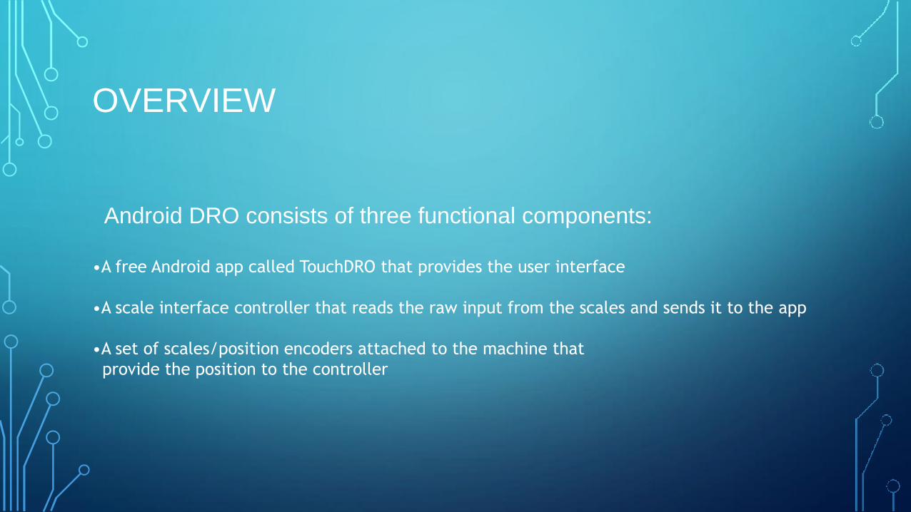
OVERVIEW
Android DRO consists of three functional components:
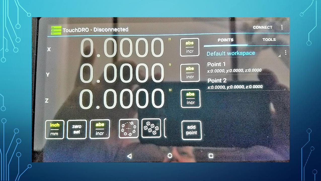
•A free Android app called TouchDRO that provides the user interface
•A scale interface controller that reads the raw input from the scales and sends it to the app
•A set of scales/position encoders attached to the machine that
provide the position to the controller
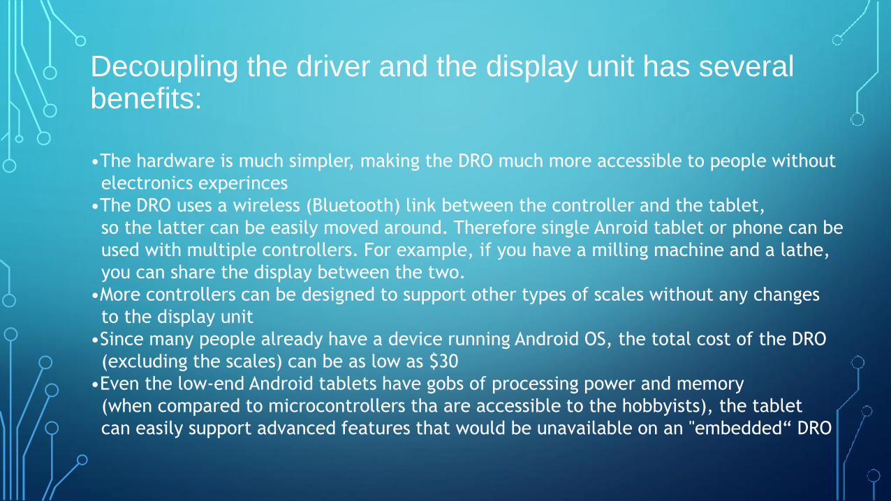
Decoupling the driver and the display unit has several benefits:
•The hardware is much simpler, making the DRO much more accessible to people without
electronics experinces
•The DRO uses a wireless (Bluetooth) link between the controller and the tablet,
so the latter can be easily moved around. Therefore single Anroid tablet or phone can be
used with multiple controllers. For example, if you have a milling machine and a lathe,
you can share the display between the two.
•More controllers can be designed to support other types of scales without any changes
to the display unit
•Since many people already have a device running Android OS, the total cost of the DRO
(excluding the scales) can be as low as $30
•Even the low-end Android tablets have gobs of processing power and memory
(when compared to microcontrollers tha are accessible to the hobbyists), the tablet
can easily support advanced features that would be unavailable on an "embedded“ DRO
TOUCHDRO APP
•Runs on an android device
•Available from Google Play or Amazon App Store
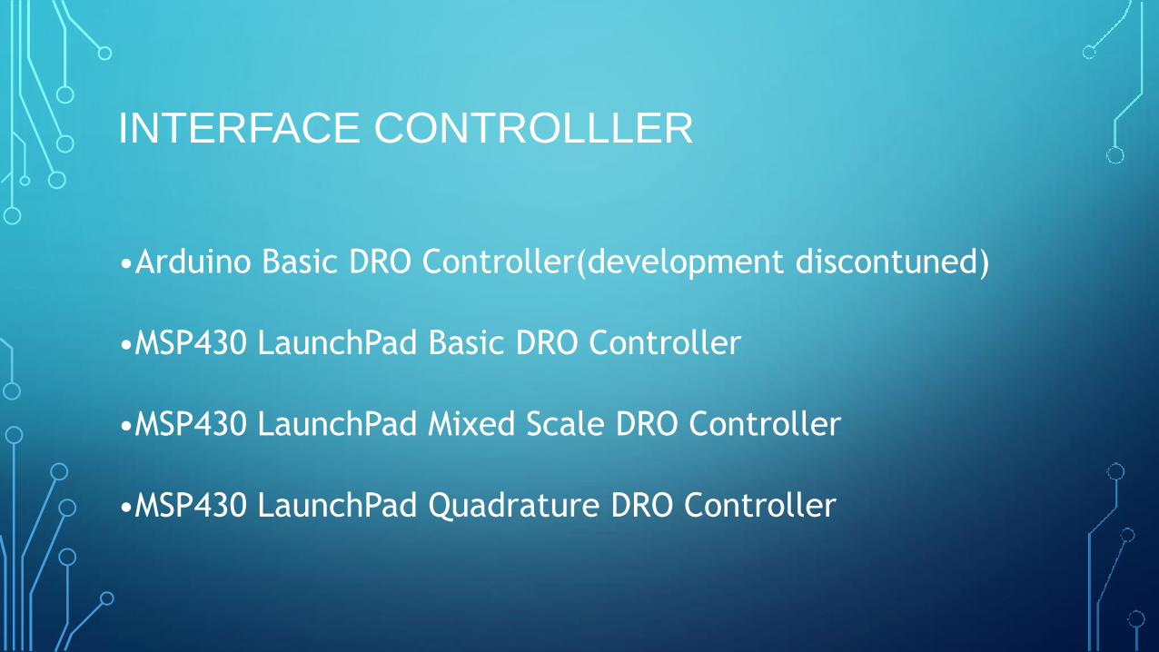
INTERFACE CONTROLLLER
•Arduino Basic DRO Controller(development discontuned)
•MSP430 LaunchPad Basic DRO Controller
•MSP430 LaunchPad Mixed Scale DRO Controller
•MSP430 LaunchPad Quadrature DRO Controller
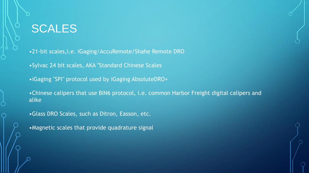
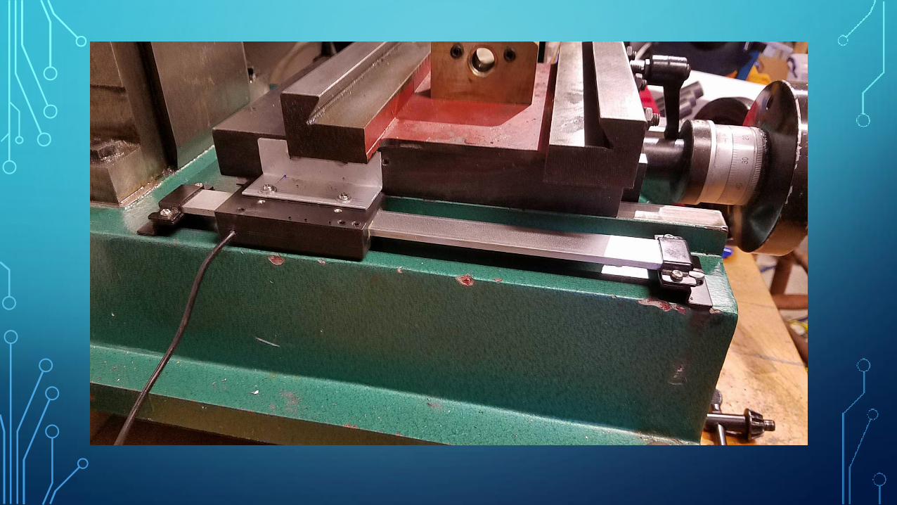
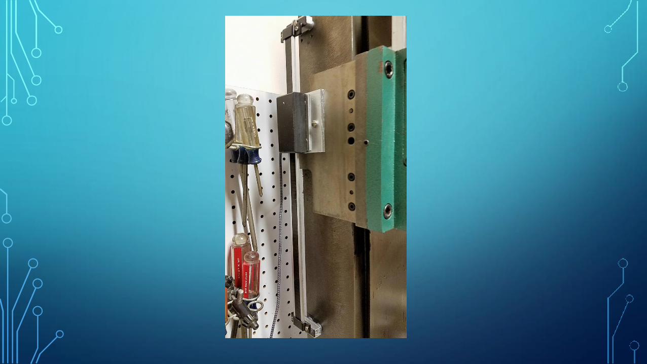
SCALES
•21-bit scales,i.e. iGaging/AccuRemote/Shahe Remote DRO
•Sylvac 24 bit scales, AKA "Standard Chinese Scales
•iGaging "SPI" protocol used by iGaging AbsoluteDRO+
•Chinese calipers that use BIN6 protocol, i.e. common Harbor Freight digital calipers and
alike
•Glass DRO Scales, such as Ditron, Easson, etc.
•Magnetic scales that provide quadrature signal
MSP430 CONTROLLER
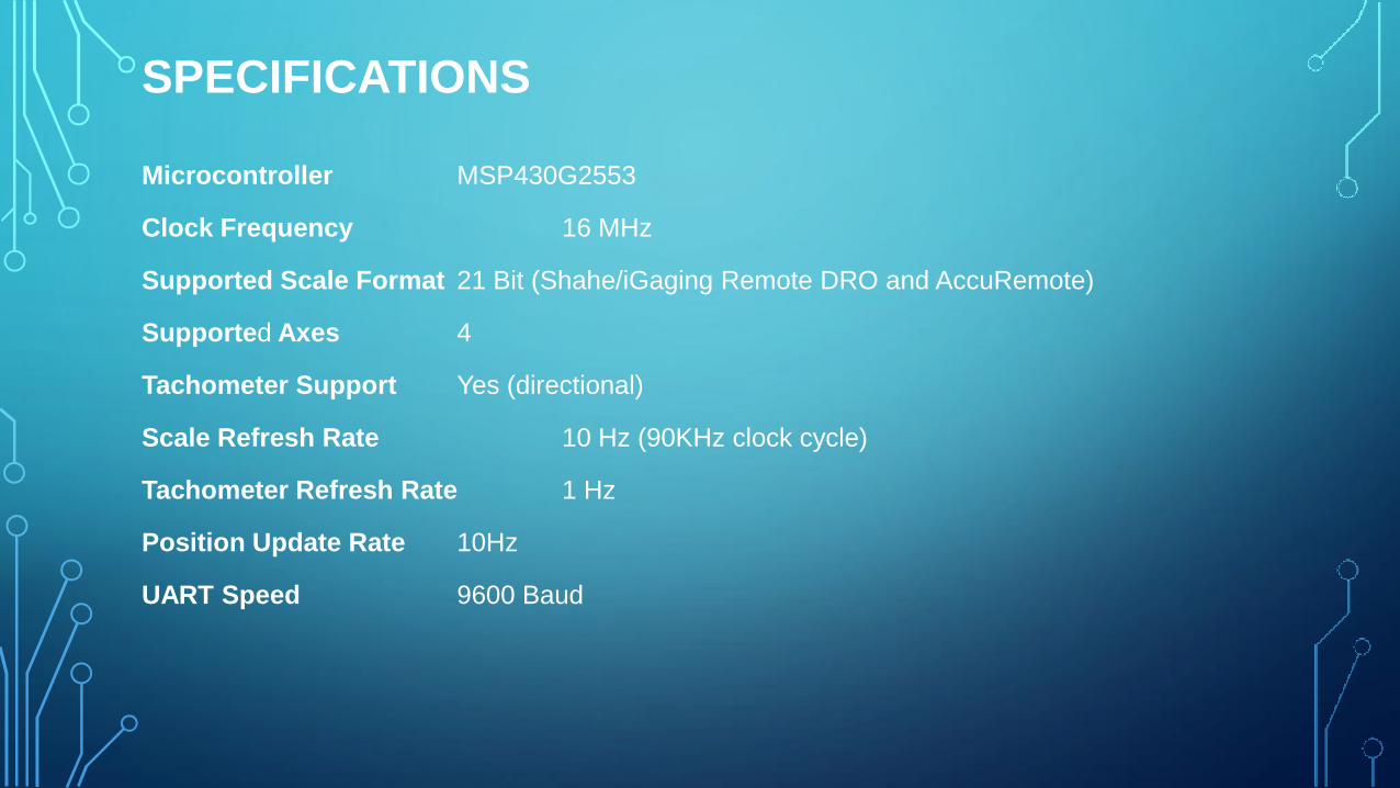
SPECIFICATIONS Microcontroller MSP430G2553
Clock Frequency 16 MHz
Supported Scale Format 21 Bit (Shahe/iGaging Remote DRO and AccuRemote)
Supported Axes 4
Tachometer Support Yes (directional)
Scale Refresh Rate 10 Hz (90KHz clock cycle)
Tachometer Refresh Rate 1 Hz
Position Update Rate 10Hz
UART Speed 9600 Baud
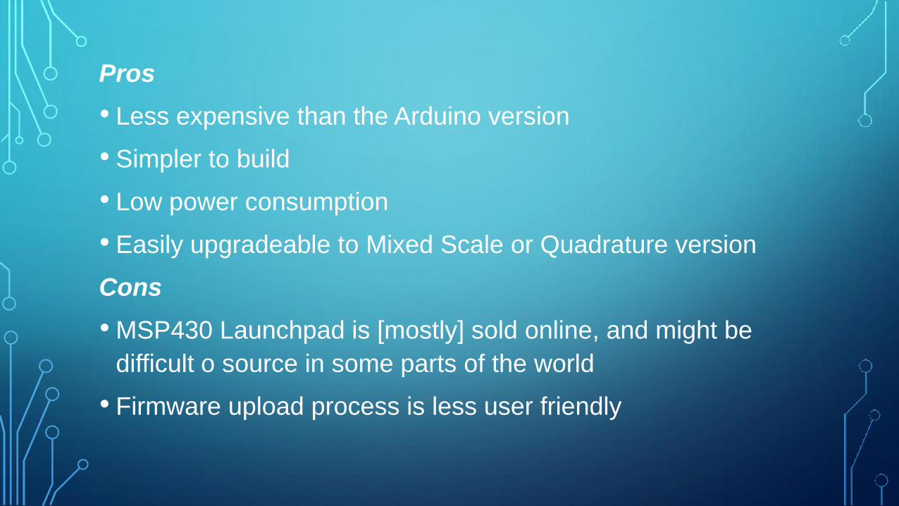
Pros
• Less expensive than the Arduino version
• Simpler to build
• Low power consumption
• Easily upgradeable to Mixed Scale or Quadrature version
Cons
• MSP430 Launchpad is [mostly] sold online, and might be
difficult o source in some parts of the world
• Firmware upload process is less user friendly
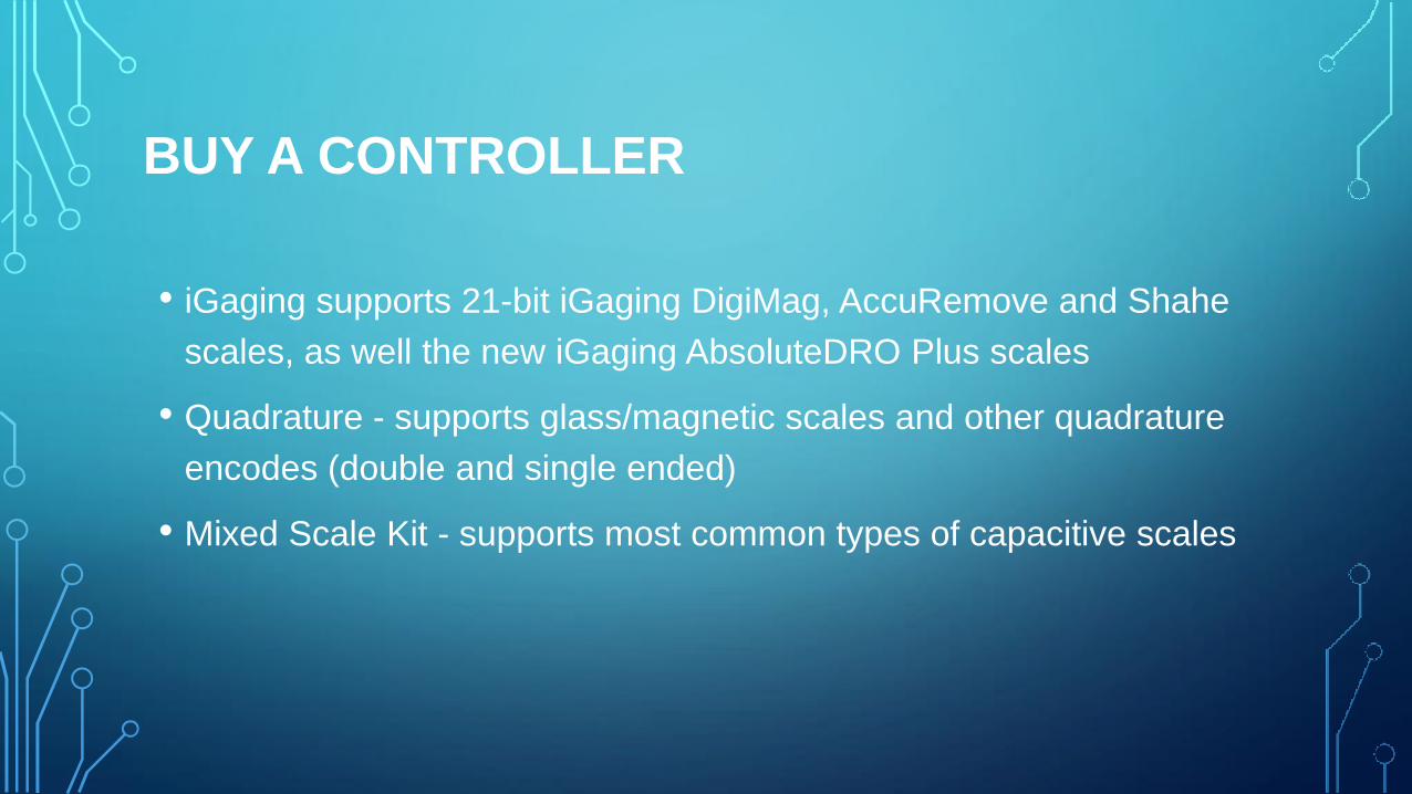
BUY A CONTROLLER
• iGaging supports 21-bit iGaging DigiMag, AccuRemove and Shahe
scales, as well the new iGaging AbsoluteDRO Plus scales
• Quadrature - supports glass/magnetic scales and other quadrature
encodes (double and single ended)
• Mixed Scale Kit - supports most common types of capacitive scales
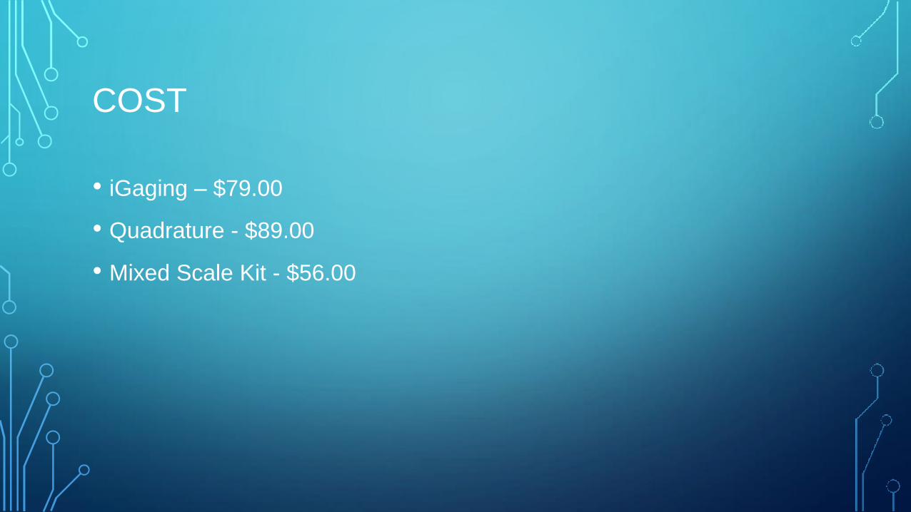
COST
• iGaging – $79.00
• Quadrature - $89.00
• Mixed Scale Kit - $56.00
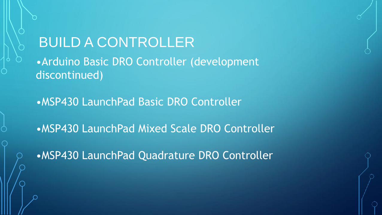
BUILD A CONTROLLER
•Arduino Basic DRO Controller (development
discontinued)
•MSP430 LaunchPad Basic DRO Controller
•MSP430 LaunchPad Mixed Scale DRO Controller
•MSP430 LaunchPad Quadrature DRO Controller
PARTS LIST
• TI MSP430 Value Line Launchpad kit
• BlueTooth Transceiver Module
• USB Phone Charger
• Terminal Connectors (optional)
• Battery Holder (optional)
• Project Box
• Diodes (optional)
• Capacitors (optional)
• Wire
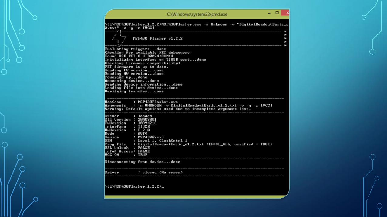
FLASHING MSP430
• Connect microcontroller to computer with USB cable
• Download flash program from TI
• Place all files including Touch DRO program in the same
dictrectory
• msp430flasher.exe -n Unknown -w "tihex.txt" -v -g -z
[VCC]
• pause
TOOLS
•Soldering Iron and solder
•Wire Cutter and Striper
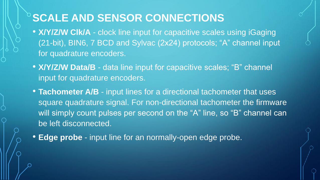
SCALE AND SENSOR CONNECTIONS • X/Y/Z/W Clk/A - clock line input for capacitive scales using iGaging
(21-bit), BIN6, 7 BCD and Sylvac (2x24) protocols; “A” channel input
for quadrature encoders.
• X/Y/Z/W Data/B - data line input for capacitive scales; “B” channel
input for quadrature encoders.
• Tachometer A/B - input lines for a directional tachometer that uses
square quadrature signal. For non-directional tachometer the firmware
will simply count pulses per second on the “A” line, so “B” channel can
be left disconnected.
• Edge probe - input line for an normally-open edge probe.
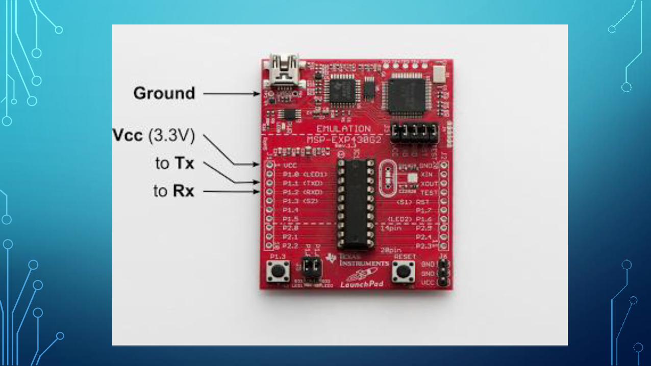
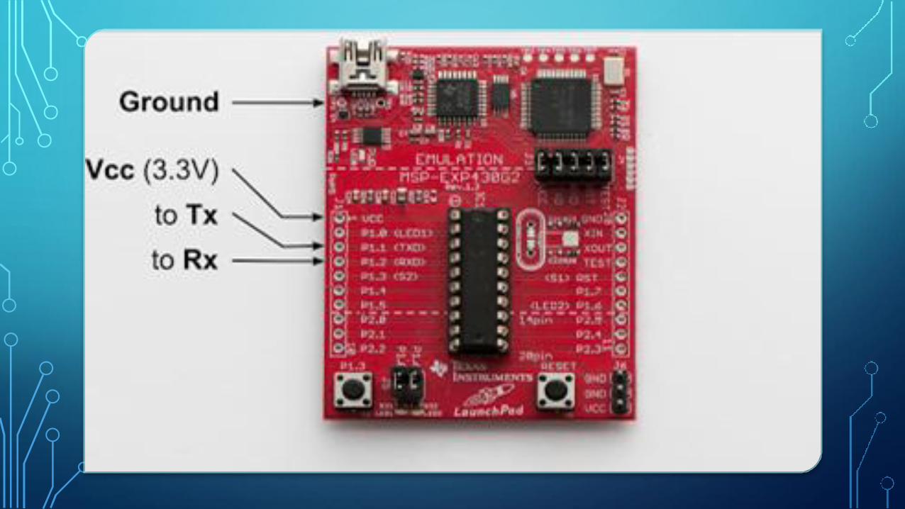
DATA CONNECTIONS
• Each UART port has two lines: Rx and Tx
• Standard connection scheme is Rx->Tx and Tx->Rx.
• Since the firmware only uses one-way communications with the
application, only MSP430’s Tx pin needs to be connected to the
adapter’s Rx.
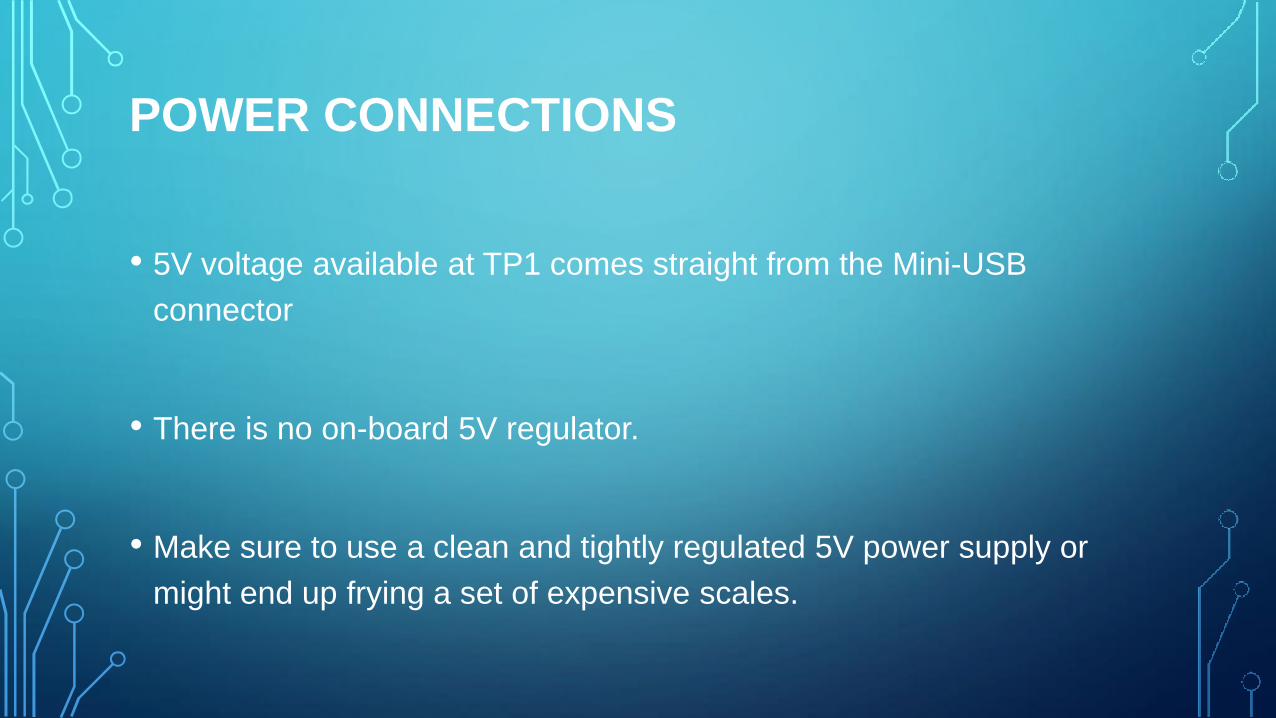
POWER CONNECTIONS
• 5V voltage available at TP1 comes straight from the Mini-USB
connector
• There is no on-board 5V regulator.
• Make sure to use a clean and tightly regulated 5V power supply or
might end up frying a set of expensive scales.
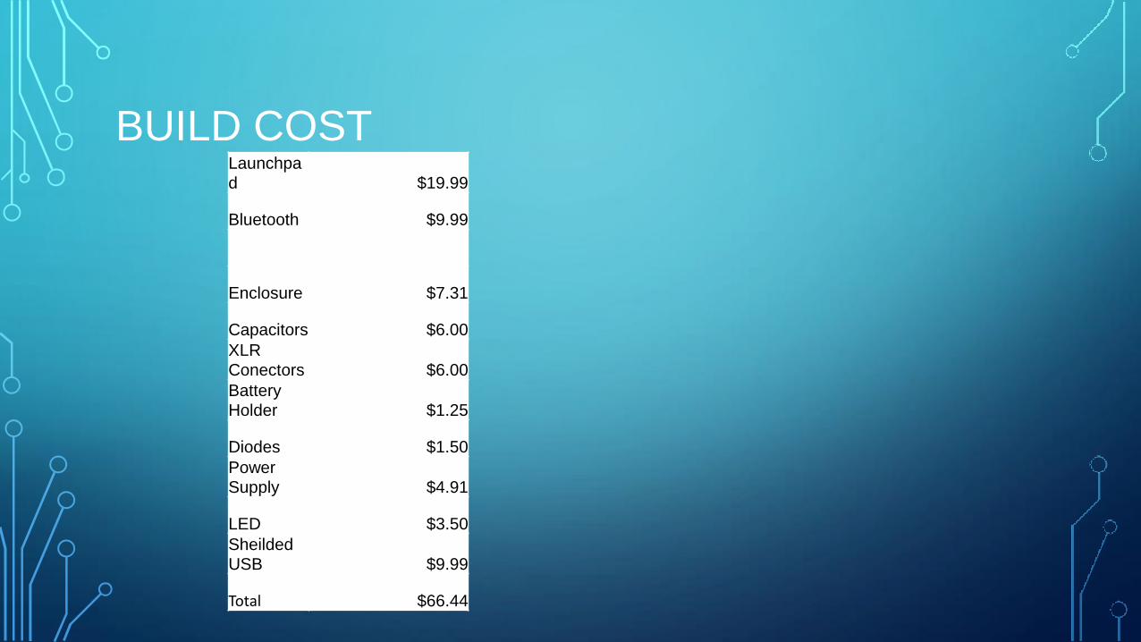
BUILD COST Launchpa
d $19.99
Bluetooth $9.99
Enclosure $7.31
Capacitors $6.00 XLR
Conectors $6.00 Battery
Holder $1.25
Diodes $1.50 Power
Supply $4.91
LED $3.50 Sheilded
USB $9.99
Total $66.44
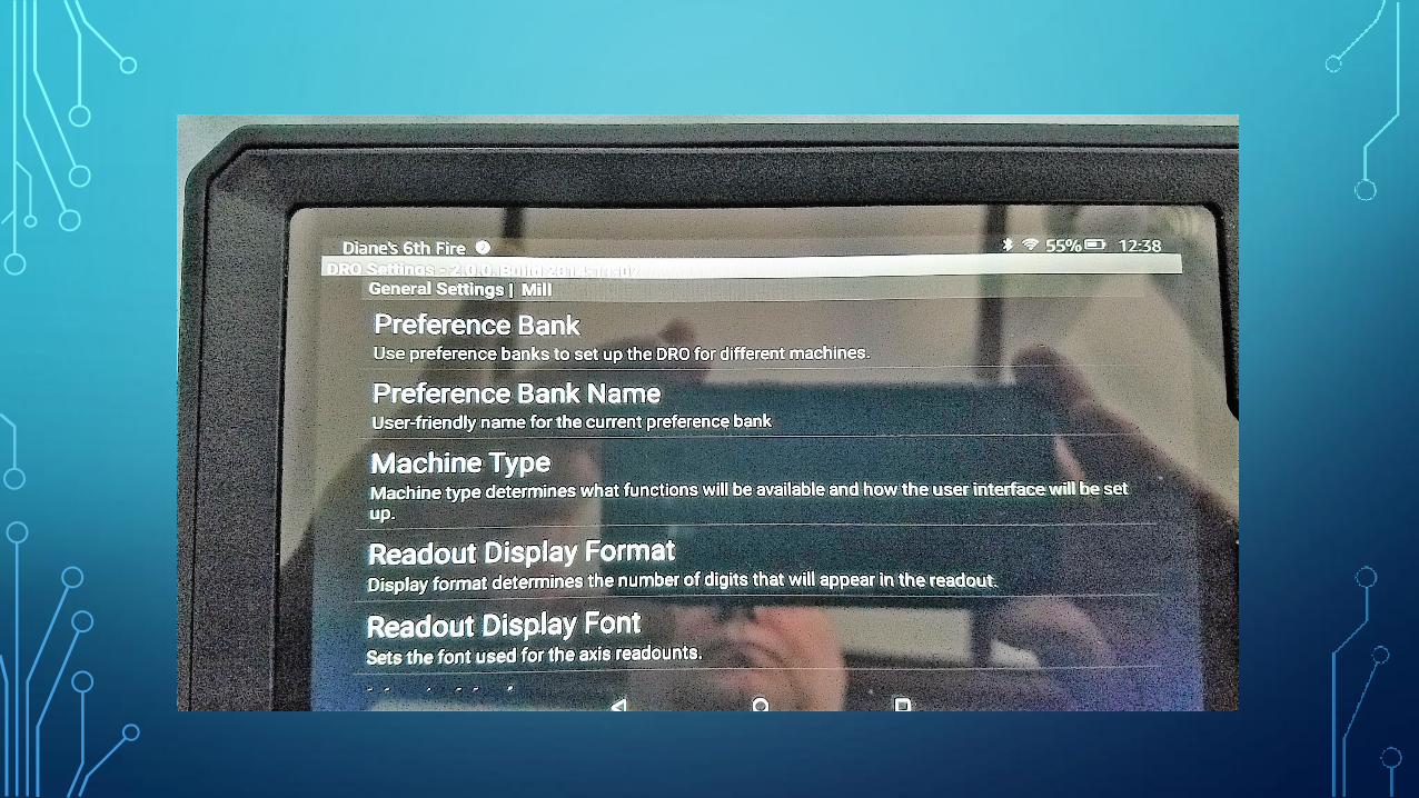
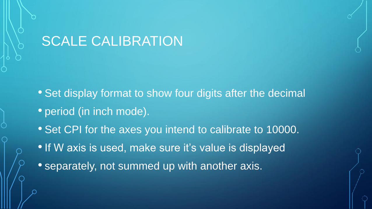
SCALE CALIBRATION
• Set display format to show four digits after the decimal
• period (in inch mode).
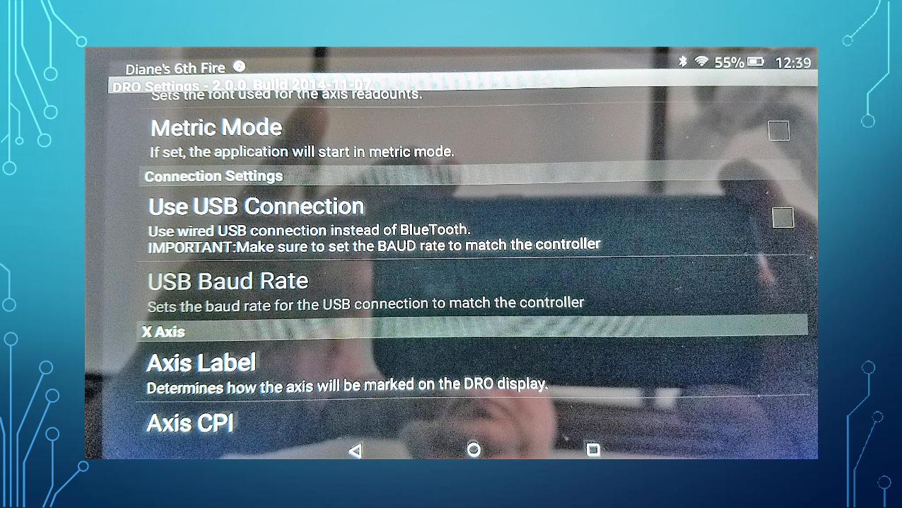
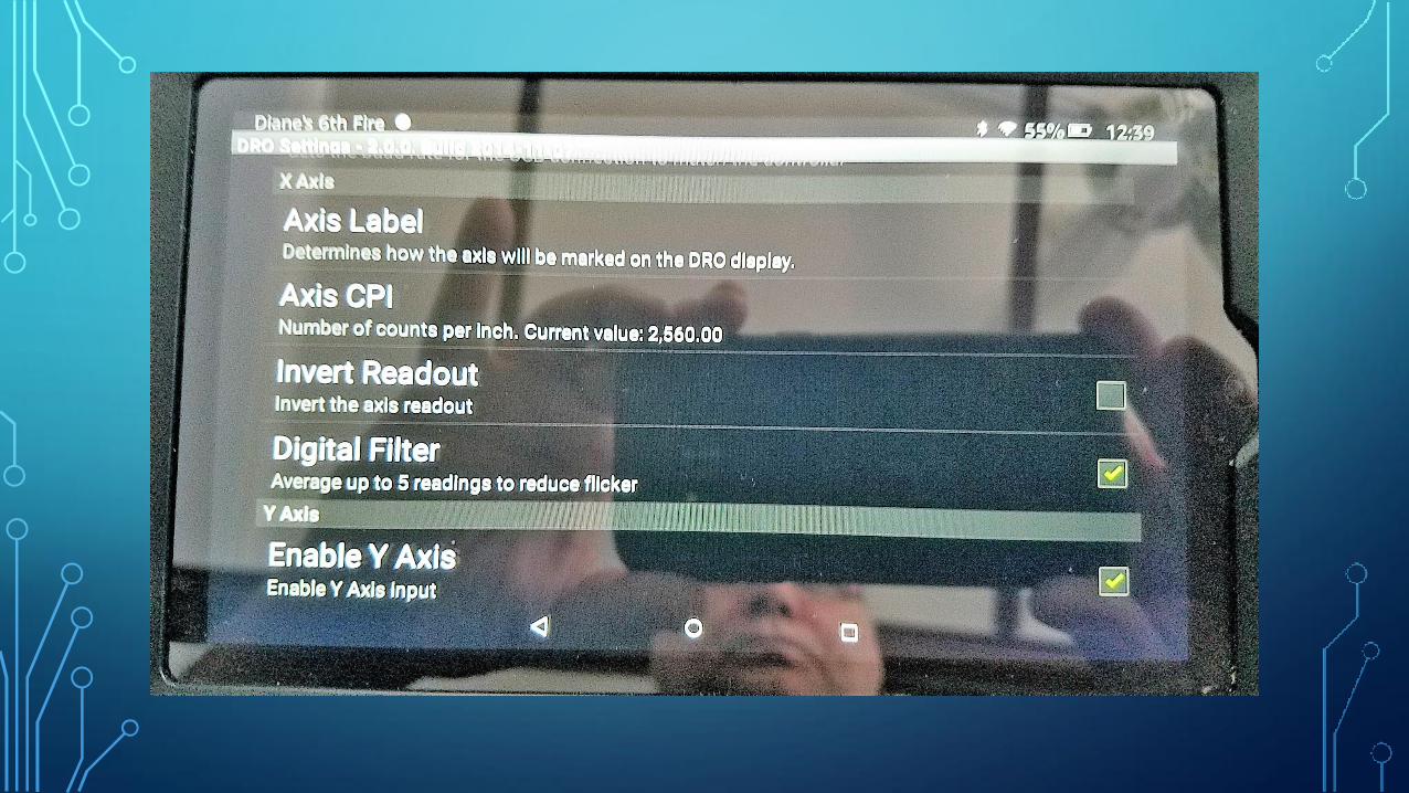
• Set CPI for the axes you intend to calibrate to 10000.
• If W axis is used, make sure it’s value is displayed
• separately, not summed up with another axis.
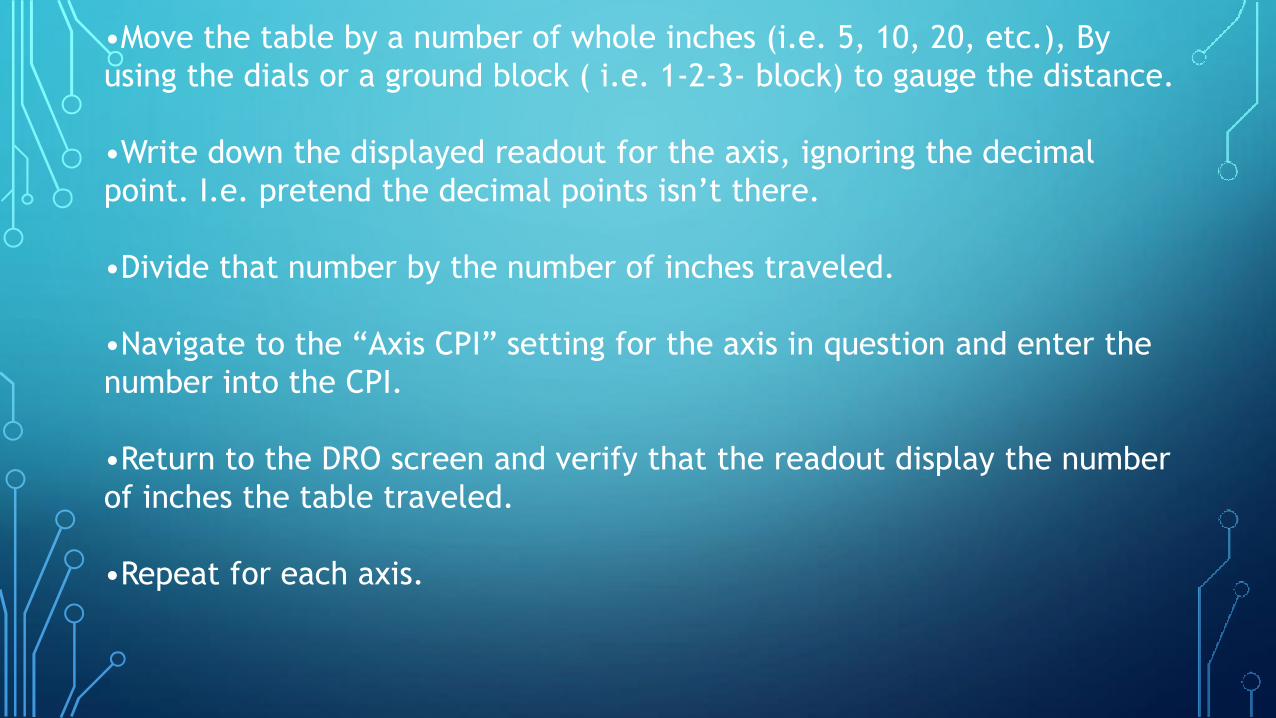
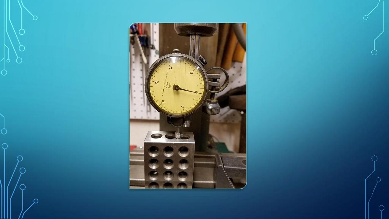
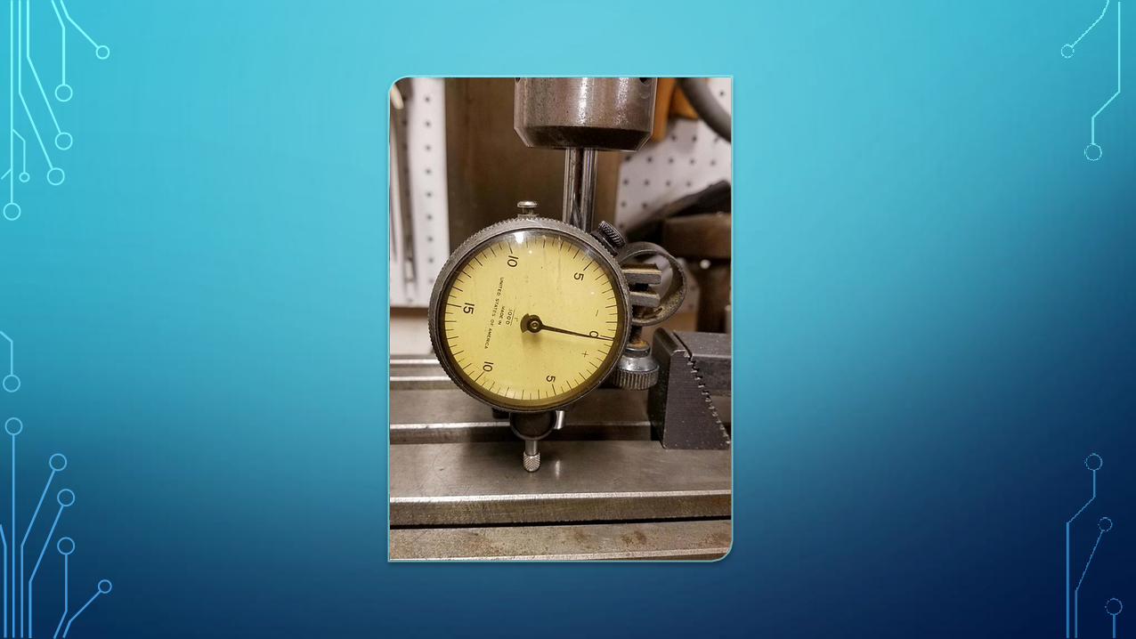
•Move the table by a number of whole inches (i.e. 5, 10, 20, etc.), By
using the dials or a ground block ( i.e. 1-2-3- block) to gauge the distance.
•Write down the displayed readout for the axis, ignoring the decimal
point. I.e. pretend the decimal points isn’t there.
•Divide that number by the number of inches traveled.
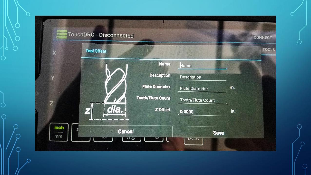
•Navigate to the “Axis CPI” setting for the axis in question and enter the
number into the CPI.
•Return to the DRO screen and verify that the readout display the number
of inches the table traveled.
•Repeat for each axis.

THINGS LEARNED T