Embed Size (px)
Citation preview

Generated using version 3.2 of the official AMS LATEX template
A flexible parameterization for shortwave optical properties of ice1
crystals2
Bastiaan van Diedenhoven ∗
Columbia University, Center for Climate System Research, New York, NY
NASA Goddard Institute for Space Research, New York, NY
3
Andrew S. Ackerman4
Brian Cairns5
Ann M. Fridlind
NASA Goddard Institute for Space Research, New York, NY
6
∗Corresponding author address: Bastiaan van Diedenhoven, 2880 Broadway, New York, NY 10025, USA
E-mail: [email protected]
1

ABSTRACT7
A parameterization is presented that provides extinction cross section (σe), single-scattering8
albedo (ω) and asymmetry parameter (g) of ice crystals for any combination of volume, pro-9
jected area, aspect ratio and crystal distortion at any wavelength in the shortwave. Similar10
to previous parameterizations, the scheme makes use of geometric optics approximations11
and the observation that optical properties of complex, aggregated ice crystals can be well12
approximated by those of single hexagonal crystals with varying size, aspect ratio and dis-13
tortion levels. In the standard geometric optics implementation used here, σe is always twice14
the particle projected area. We show that ω is largely determined by the newly defined15
absorption size parameter and the particle aspect ratio. These dependences are parameter-16
ized using a combination of exponential, lognormal and polynomial functions. The variation17
of g with aspect ratio and crystal distortion is parameterized for one reference wavelength18
using a combination of several polynomials. The dependences of g on refractive index and19
ω are investigated and factors are determined to scale the parameterized g to provide values20
appropriate for other wavelengths. The parameterization scheme consists of only 88 coeffi-21
cients. The scheme is tested for a large variety of hexagonal crystals in several wavelength22
bands from 0.2 to 4 µm, revealing absolute differences with reference calculations of ω and23
g that are both generally below 0.015. Over a large variety of cloud conditions, resulting24
root-mean-squared differences with reference calculations of cloud reflectance, transmittance25
and absorptance are 1.4%, 1.1% and 3.4%, respectively. Some practical applications of the26
parameterization in atmospheric models are highlighted.27
1

1. Introduction28
A substantial uncertainty in properly representing ice clouds and consequently their cli-29
mate feedbacks is characterizing their radiative properties (Stephens et al. 1990; Stackhouse30
and Stephens 1991; Schlimme et al. 2005; Fu 2007). The fundamental radiative properties31
of atmospheric ice crystals for atmospheric models are the ice extinction cross section, single32
scattering albedo and the first moment of the scattering phase function, commonly referred33
to as the asymmetry parameter (Coakley and Chylek 1975; Fu 1996; Yang et al. 2000; Fu34
2007). An increasing number of parameterizations for these optical properties of ice clouds35
are available. Such parameterizations generally relate the optical properties in selected wave-36
length bands in terms of predicted or imposed bulk characteristics of the ice, such as effective37
size, shape and ice water content (e.g., Fu and Liou 1993; Fu 1996; Wyser and Yang 1998;38
Kristjansson et al. 1999; Yang et al. 2000; McFarquhar et al. 2002; Key et al. 2002; Edwards39
et al. 2007; Xie et al. 2012), sometimes in combination with atmospheric conditions, such as40
temperature and ice supersaturation (Kristjansson et al. 2000; Baran 2012). Although ice41
crystals are found with a virtually countless variation of shapes (Baran 2009), the extinction42
cross section and single scattering albedo of randomly oriented individual ice crystals mainly43
depend on their projected areas and volumes, while the asymmetry parameter is shown to44
be mainly determined by the aspect ratios (defined throughout as the ratio of hexagonal45
prism height to width) of the ice crystal hexagonal components and their microscale surface46
roughness or crystal distortion (Iaquinta et al. 1995; Macke et al. 1996; Fu 2007; Yang and47
Fu 2009; Baran 2009; van Diedenhoven et al. 2012a).48
Parallel to advances in understanding ice optical properties are efforts to improve ice49
microphysics modeling schemes. Some of these schemes are becoming increasingly complex50
and calculate or parameterize ice fall speeds and capacitances (an electrostatic analog used51
to compute ice deposition and sublimation rates) in terms of ice mass, projected area and52
aspect ratio (Bohm 1989, 1992; Heymsfield and Iaquinta 2000; Wood et al. 2001; Westbrook53
2008; Westbrook et al. 2008; Sulia and Harrington 2011; van Diedenhoven et al. 2012b).54
2
Since mass m can be related to bulk ice volume V via V = m/ρi, where ρi is the density of55
bulk ice, the ice characteristics determining fall speeds and capacitances are largely the same56
as those determining ice optical properties. Only crystal distortion does not affect fall speeds57
and capacitances substantially while being important for ice crystal optical properties. Self58
consistency within a model dictates that the same ice volume, area and aspect ratio used59
in an ice microphysics scheme should also be used in a model’s radiative transfer scheme60
(Mitchell et al. 2008; Baran 2012). However, there is at present a lack of optical property61
parameterizations flexible enough to accommodate all possible combinations of ice volume,62
area, aspect ratio, and crystal distortion. Furthermore, optical properties parameterizations63
are usually given for a predetermined set of wavelength bands, which are not necessarily64
the same as those used in a model’s radiative transfer calculations. Finally, most current65
optical property schemes require many and large tables to be read by the radiative transfer66
algorithm.67
In this paper, we present a simple yet flexible parameterization that provides the ex-68
tinction cross section, single-scattering albedo and asymmetry parameter of ice crystals for69
any combination of volume, projected area, aspect ratio (of crystal components) and crystal70
distortion and at any wavelength in the shortwave. Similar to previous parameterizations71
(e.g., Fu 1996, 2007), our scheme makes use of geometric optics approximations and the72
observation that optical properties of complex, aggregated ice crystals can be approximated73
by those of single hexagonal crystals with varying size, aspect ratio and crystal distortion.74
After describing the reference calculations, the theory and the parameterization in section75
2, we assess its accuracy in section 3. We provide an example of an application in section 476
and present conclusions in section 5.77
3

2. Theory and parameterizations78
Here, we first discuss the dependencies of extinction cross section, absorption cross section79
and asymmetry parameter on ice crystal volume, projected area, aspect ratio and crystal80
distortion before parameterizing those dependencies.81
a. Reference calculations82
The reference calculations are based on single hexagonal plates and columns. The optical83
properties for hexagonal plates and columns with random orientation are calculated using84
the geometric optics (GO) code developed by Macke et al. (1996). In this standard geometric85
optics implementation, the extinction cross section is twice the projected area of crystals in86
random orientation. This Monte Carlo ray tracing code takes crystal distortion of ice crystals87
into account in a statistical manner by perturbing the normal of the crystal surface from its88
nominal orientation by an angle that, for each interaction with a ray, is varied randomly with89
uniform distribution between 0o and δ×90o, where δ is referred to as the distortion parameter.90
Thus, the distortion parameter δ does not represent a single realization of a distorted crystal,91
but rather the stochastic large-scale distortion of a collection of ice crystals (Macke et al.92
1996). For a large collection of ice crystals, microscale surface roughness and large-scale93
particle distortion both lead to a similar randomization of the angles between crystal facets,94
which in turn leads to the suppression of features in the scattering phase matrix (Yang et al.95
2008; Neshyba et al. 2013). Increasing the number of impurities within ice crystals also has a96
similar effect (Hess et al. 1998). Thus, the distortion parameter used here can be considered97
as a proxy for the randomization of the angles between crystal facets caused by any of these98
effects.99
Calculations are made for bands with the average wavelengths and complex refractive100
indices listed in Table 1. Various sets of calculations including different dimensions of the101
hexagonal particles are used to construct and evaluate the parameterization, as detailed in102
4

the next subsections. The relations between volume V , orientation-averaged projected area103
Ap, maximum half-width of the hexagonal planes ahex and aspect ratio α of hexagonal plates104
and columns are given in the Appendix.105
The reference calculations and thus the parametrization presented here are based on con-106
ventional geometric optics calculations. It is generally excepted that GO approximations are107
applicable to scattering size parameters above about 100 (e.g., Macke et al. 1995; Yang et al.108
2000, 2004, 2013). (Here we define the particle scattering size parameter χscat as 2π rsph/λ,109
where rsph is the radius of a sphere with the equivalent projected area, i.e., rsph =√
Ap/π.)110
For smaller sizes, the errors on ice crystal optical properties and ice cloud radiation calcula-111
tions caused by GO approximations are not yet adequately quantified. Such a quantification112
would require intensive calculations using techniques that are able to accurately calculate113
optical properties of a variety of ice crystal shapes with small size parameters (e.g., Yang114
et al. 2013). Such a investigation is beyond the scope of the current paper and left for future115
work.116
b. Extinction cross section and single scattering albedo117
The single-scattering albedo ω of a single ice particle is defined to be118
ω = 1− σa
σe
, (1)
where the extinction cross section σe of a particle is given by119
σe = QeAp, (2)
where Ap is the orientation-averaged projected area of the particle, and Qe is the extinction120
efficiency, which is equal to 2 in the geometric optics limit (Macke et al. 1996; Yang and Liou121
1996). According to anomalous diffraction theory (ADT, van de Hulst 1957; Bryant and La-122
timer 1969; Mitchell and Arnott 1994), the absorption cross section σa can be approximated123
by124
σa ≈[
1− exp(−4πmiV
λAp
)
]
Ap, (3)
5

where mi is the imaginary part of the refractive index m (Table 1) at wavelength λ, and V125
is the volume of the ice crystal, which is related to mass m via V = m/ρi, where ρi is the126
bulk density of ice. From Eqs. 1, 2, and 3 it is apparent that the single scattering albedo at127
a given wavelength is mainly determined by the ice crystal effective distance or photon path128
de as given by Bryant and Latimer (1969):129
de =V
Ap
. (4)
The relation between the single scattering albedo of a compact hexagonal particle with130
aspect ratio α of unity and the effective distance for the wavelength bands with substantial131
absorption is shown in Fig. 1a. For this, calculations were made for smooth crystals with132
100 different ratios of volume to projected area varying between 1 and 135 µm. The effect133
of particle distortion on single scattering albedo is considered negligible (Yi et al. 2013).134
The ice crystal effective distance is related to the commonly used, but variably defined135
(McFarquhar and Heymsfield 1998) bulk ice effective diameter De in which ”bulk” denotes136
an average over a particle size distribution. Here we define De through the ratio of the137
size-distribution integrated volume and project area:138
De =3
2
∫∞
0V (D)N(D) dD
∫∞
0Ap(D)N(D) dD
, (5)
where N is the number density of the ice crystals of maximum dimension D (Foot 1988;139
Francis et al. 1994; Baum et al. 2005a). The smooth relation of the single scattering albedo140
to the ratio of volume to area has often been used to parameterize the single scattering141
albedo as a function of bulk ice effective diameter (e.g., Wyser and Yang 1998; Yang et al.142
2000; McFarquhar et al. 2002; Key et al. 2002; Edwards et al. 2007; Xie et al. 2012).143
However, Eq. 3 suggests that a more fundamental parameter governing the single scat-144
tering albedo of individual particles is145
χabs =miV
λAp
=mi
λde, (6)
which we will refer to as the absorption size parameter. Note that χabs is dimensionless. As146
seen in Fig. 1b, the single scattering albedo in nearly all bands collapse to a single function147
6
of χabs. Only single scattering albedos corresponding to the two bands with the strongest148
absorption (2.6 µm and 3.3 µm with mi > 0.02 as seen in table 1) substantially deviate from149
the single curve. For the remaining bands, single scattering albedos at the same absorption150
size parameter but for different wavelengths agree within about 0.01, to be discussed in151
greater detail later. The dependence of single scattering albedo for compact particles (ωα=1)152
to absorption size parameter is found to be fit well by an exponential function:153
ωα=1 = 1− a0(1− e−a1 χabs), (7)
where the form of the parametrization guarantees that ωα=1 = 1 for χabs = 0. Using a154
least-squares fit, we find a0 = 0.457593 and a1 = 20.9738. (The parameterization coefficients155
are computed in single precision with 4-byte floating points and given to six significant digits156
throughout.) The values corresponding to the 2.6 µm and 3.3 µm bands with strong absorp-157
tion were excluded when performing this fit. The root-mean-squared difference between the158
fit and the single scattering albedos used for the fit is 0.002. As evident from Fig. 1b, errors159
for strongly absorbing wavelengths are larger, as further discussed in section 3. As can be160
derived from Eqs. 1–3, in conventional ADT the coefficients a0 and a1 of Eq. 7 are 1/Qe161
and 4π, respectively (Mitchell and Arnott 1994). However, Fig. 1b shows that ADT gener-162
ally overestimates the single scattering albedo of compact hexagonal crystals. As discussed163
by Mitchell et al. (1996) among others, this error is principally attributable to the neglect164
of internal reflections. Several modifications to ADT have been proposed (e.g., Mitchell165
2002; Yang et al. 2004), which generally include several tuning factors; an evaluation of such166
schemes is beyond the scope of this study. Note that a quantity related to the absorption167
size parameter (Eq. 6) was used previously by Takano and Liou (1989) to parameterize ω168
for weakly absorbing (ω < 0.75) hexagonal crystals at wavelengths shorter than 2.5 µm.169
The parameterization described by Eq. 7 assumes compact hexagonal ice crystals (α = 1).170
When aspect ratios deviate from unity by about a factor 2, ω is generally greater than that171
of a compact hexagonal crystal, as seen in Fig. 2. This effect is stronger for plates (Fig. 2a)172
than for columns (Fig. 2b). Presumably this increase of ω with aspect ratio deviating from173
7

unity results from a decrease of the orientation-averaged path length through the particle,174
because internal reflections are maximized for compact particles. Similarly to Fig. 1b,175
Fig. 2 shows that, for a given aspect ratio, ω collapses to a single function of χabs. Note176
however that slight differences in ω at the same χabs but for different combinations of de177
and wavelengths result in ”spikes” in Fig. 2. Such spikes may result from wave resonance178
effects, leading to rays orbiting the particle through a series of internal reflections for specific179
combinations of wavelength, refractive index and particle size, thereby increasing absorption180
(Guimaraes and Nussenzveig 1992; Mitchell et al. 2006). Interestingly, the spikes diminish181
as aspect ratio increasingly deviates from unity, which is consistent with such ray orbiting182
phenomena (Mitchell et al. 2006). However, some Monte Carlo noise is also apparent in Fig.183
2, which increases with aspect ratio deviation from unity. Figure 2 also shows functional184
fits to the χabs versus ω relations for plates with aspect ratios of 0.8, 0.5, 0.2, 0.1, 0.05 and185
0.02 and for columns with aspect ratios that are the inverse of those for the plates. First,186
the difference (∆ωα) between the calculated single scattering albedo and the exponential fit187
assuming compact hexagonal crystals (Fig. 1b and Eq. 7) is determined for each of the188
aspect ratios, as shown in Fig. 3. We find that ∆ωα can be approximated by log-normal189
functions that are also shown in Fig. 3, i.e.,190
∆ωα ≈ l0√2πl2 χabs
exp
(
−(ln χabs − l1)2
2l22
)
. (8)
The fit parameters li, where i is 0–2, are determined for each of the aspect ratios using a191
least-squares fitting method. In turn, li are found to be smooth functions of the logarithm192
of the aspect ratio α that, for either plates and columns, can be approximated by cubic193
functions, i.e.,194
li(α) =3
∑
j=0
ci,j logjα, (9)
for which the coefficients ci,j are listed in Table 2. (Throughout, ”log” refers to base 10.) To195
better constrain this latter fit we also include calculations for aspect ratios of 0.01 and 100,196
which are not shown in Figs. 2 and 3. Finally, the single scattering albedo of a hexagonal197
8

ice crystal of any size and any aspect ratio can be estimated for any wavelength by198
ω(χabs, α) = ωα=1 +∆ωα, (10)
where ωα=1 and ∆ωα are calculated using Eqs. 7 and 8, respectively. Note that the spikes199
and noise seen in Fig. 2, as mentioned above, are even more apparent in Fig. 3. Given that200
such spikes are about 0.01 ω units in magnitude, the parameterization of ω is limited to an201
overall accuracy of about 0.01 at wavelengths where mi < 0.02. The resulting parameterized202
single scattering albedo as a function of the absorption size parameter and aspect ratios for203
plates and columns is shown in Fig. 5. The parameterization of ω is summarized in Fig. 4.204
As given by Eq. 2, the extinction cross section is always twice the projected area of205
crystals in random orientation in the standard geometric optics implementation used here206
(see Fig. 4, box 5). This approximation generally holds for scattering size parameters above207
about 50 (e.g., Yang et al. 2000, 2004, 2013). For particles with smaller scattering size208
parameters (1–50), so-called edge effects and wave interference have to be taken into account209
(Mitchell 2000; Yang et al. 2013), which lead to a general increase of the extinction coefficient210
up to about 3 with decreasing size parameter and to oscillations in the extinction coefficient211
in size parameter space of about 20% or smaller. For yet smaller size parameters (χscat < 1),212
particles are comparable to or smaller than the wavelength and transition to the Rayleigh213
regime, associated with a decrease of extinction coefficient with decreasing size. Since the214
parametrization presented in this paper are based on calculations based on the standard215
geometric optics approximations, these effects are neglected and Qe is assumed to be equal216
to 2 for all sizes. Thus, substantial errors in the extinction coefficient owing to the geometric217
optics approximation can be expected for small ice crystals. However, the contribution of218
these small crystals to the total extinction cross section is expected to be generally minor219
under many conditions, owing to their small projected area. To our best knowledge, a proper220
quantification of the errors in extinction cross sections and ice cloud radiation simulations221
resulting from the approximation Qe = 2 is not yet available. As discussed in section 2a,222
such a investigation is beyond the scope of the current paper and left for future work.223
9

c. Asymmetry parameter224
In the geometrics optics regime, the total scattering phase function Ptot includes con-225
tributions from internal refraction and reflections PRT (determined using ray tracing) and226
contributions from diffraction Pdif (Macke et al. 1996):227
Ptot(θ) =1
2ω
[
(2ω − 1)PRT(θ) + Pdif(θ)]
. (11)
The scattering phase function is often characterized by its first moment, the asymmetry228
parameter gtot (Macke et al. 1996):229
gtot =
∫ π
0
Ptot cos θ sin θ dθ =1
2ω
[
(2ω − 1)gRT + gdif
]
. (12)
where gdif and gRT are the asymmetry parameters of the diffractive contributions and the230
refractive plus reflective (or ray tracing) contributions to the phase function, respectively.231
A parameterization of single scattering albedo ω is presented in the previous section. Note232
that at non-absorbing wavelengths (ω = 1), Eq. 12 reduces to233
gtot =1
2(gRT + gdif). (13)
Here we aim to parameterize gdif and gRT as a function of particle volume, projected area,234
aspect ratio, distortion parameter and wavelength. Then Eq. 12 can be used to obtain the235
total asymmetry parameter for any hexagonal ice crystal at any wavelength.236
As shown in Fig. 6, the diffraction asymmetry parameter is mainly determined by the237
particle scattering size parameter χscat. For χscat larger than about 100, gdif = 1. For smaller238
χscat, gdif can be calculated analytically with series of Bessel functions (van de Hulst 1957;239
Macke et al. 1996; Mishchenko and Macke 1998). Here, we simply approximate it with a240
parametric form justified by the integral over a diffraction pattern:241
gdif = b0 eb1 ln χscat + b2, (14)
with b0 = −0.822315, b1 = −1.20125 and b2 = 0.996653, as shown in Fig. 6. The coefficients242
were obtained using a least-squares fit. The diffraction asymmetry parameter is limited to243
be greater than 0.5. This parameterization of gdif is summarized in Fig. 7, boxes 1 and 2.244
10
The refraction plus reflection asymmetry parameter gRT depends on particle volume,245
projected area, aspect ratio, distortion parameter and complex refractive index. However,246
at any given non-absorbing wavelength, gRT of single hexagonal ice crystals mainly depends247
on aspect ratio and crystal distortion (cf. Fu 2007; Yang et al. 2008; Yang and Fu 2009;248
van Diedenhoven et al. 2012a). For example, Fig. 8 shows the total asymmetry parameter249
at a non-absorbing wavelength of λ =862 nm as a function of distortion parameter δ for250
several aspect ratios. Note that these calculations are made for large particles (χscat ≫ 100),251
and thus gdif = 1 and the dependencies of the total asymmetry parameter on aspect ratio252
and distortion parameter seen in Fig. 8 are solely attributable to variations in gRT (see Eq.253
13). Here, the wavelength band at 862 nm is used as a reference because it corresponds254
to similar bands commonly used in aircraft and satellite retrievals of ice cloud properties255
(e.g., Chepfer et al. 2001; King et al. 2004; van Diedenhoven et al. 2012a,b). Similarly as256
described by van Diedenhoven et al. (2012a), sizes are varied so that the projected areas257
of the particles, assuming random orientation, correspond to the projected areas of spheres258
with radii of 14, 20, 28, 40, 56, 80, 113, 160, 226 and 320 µm. The aspect ratio of columns is259
varied between 1 and 50 with 26 geometrically increasing steps. The aspect ratios of plates260
are the inverse of those for columns, for a total of 51 aspect ratios. The distortion parameter261
is varied between 0 and 0.8 in steps of 0.05. Since GO calculations are independent of size262
for large particles, results are simply averaged over all sizes in order to decrease numerical263
noise. In the following, we aim to first parameterize the total asymmetry parameter at264
λ = 862 nm from which we derive the refraction plus reflection asymmetry parameter gRT265
at λ = 862 nm using Eq. 13. Subsequently, we derive factors to scale the resulting gRT to266
other wavelengths, that is, for other complex refractive indices.267
Figure 8 shows that asymmetry parameters increase as aspect ratio departs from unity268
owing to the increase of parallel surface areas, leading to greater probability of light passing269
through the particle with low orders of refraction plus reflection and a minimal change of270
direction (Yang and Fu 2009). Increase of crystal distortion increases the chance of light271
11
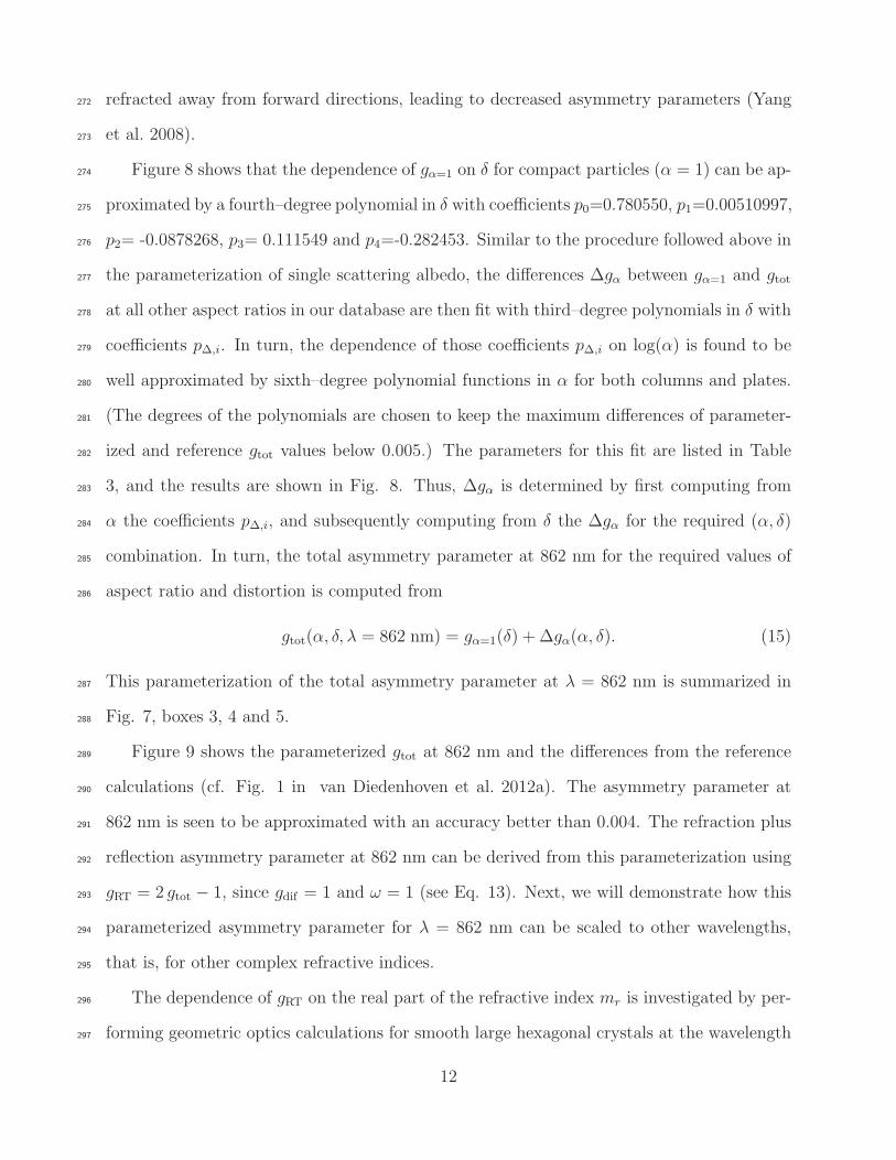
refracted away from forward directions, leading to decreased asymmetry parameters (Yang272
et al. 2008).273
Figure 8 shows that the dependence of gα=1 on δ for compact particles (α = 1) can be ap-274
proximated by a fourth–degree polynomial in δ with coefficients p0=0.780550, p1=0.00510997,275
p2= -0.0878268, p3= 0.111549 and p4=-0.282453. Similar to the procedure followed above in276
the parameterization of single scattering albedo, the differences ∆gα between gα=1 and gtot277
at all other aspect ratios in our database are then fit with third–degree polynomials in δ with278
coefficients p∆,i. In turn, the dependence of those coefficients p∆,i on log(α) is found to be279
well approximated by sixth–degree polynomial functions in α for both columns and plates.280
(The degrees of the polynomials are chosen to keep the maximum differences of parameter-281
ized and reference gtot values below 0.005.) The parameters for this fit are listed in Table282
3, and the results are shown in Fig. 8. Thus, ∆gα is determined by first computing from283
α the coefficients p∆,i, and subsequently computing from δ the ∆gα for the required (α, δ)284
combination. In turn, the total asymmetry parameter at 862 nm for the required values of285
aspect ratio and distortion is computed from286
gtot(α, δ, λ = 862 nm) = gα=1(δ) + ∆gα(α, δ). (15)
This parameterization of the total asymmetry parameter at λ = 862 nm is summarized in287
Fig. 7, boxes 3, 4 and 5.288
Figure 9 shows the parameterized gtot at 862 nm and the differences from the reference289
calculations (cf. Fig. 1 in van Diedenhoven et al. 2012a). The asymmetry parameter at290
862 nm is seen to be approximated with an accuracy better than 0.004. The refraction plus291
reflection asymmetry parameter at 862 nm can be derived from this parameterization using292
gRT = 2 gtot − 1, since gdif = 1 and ω = 1 (see Eq. 13). Next, we will demonstrate how this293
parameterized asymmetry parameter for λ = 862 nm can be scaled to other wavelengths,294
that is, for other complex refractive indices.295
The dependence of gRT on the real part of the refractive index mr is investigated by per-296
forming geometric optics calculations for smooth large hexagonal crystals at the wavelength297
12

bands listed in Table 1, but artificially setting the imaginary part of the refractive index to298
zero (i.e., ω = 1). Figure 10 shows that gRT relative to its value at 862 nm (mr = 1.3038) is299
a smooth function of mr for a given aspect ratio. We hypothesize that, as Fresnel reflection300
on the particle surfaces is increased with an increasing refractive index, forward scattering301
is reduced and backward scattering is increased (i.e., asymmetry parameter is lowered). It302
is seen in Fig. 10 that the ratio of the asymmetry parameter with a certain refractive index303
mr,1 to that with another refractive index mr,2 is reasonably well approximated by functions304
of the form305
Cmr=
(mr,1 − ǫ)
(mr,1 + ǫ)
(mr,2 + ǫ)
(mr,2 − ǫ), (16)
where ǫ is a fitting coefficient that depends on aspect ratio. Since we use calculations at306
862 nm as a reference, here mr,1 = 1.3038. The functional form of Eq. 16 is inspired by the307
Fresnel equation for reflection (Born and Wolf 1999). The parameter ǫ is computed from the308
value that minimizes the root-mean-squared difference between Eq. 16 and gRT(mr,2) over309
the range of mr,2 in Table 1. ǫ is found to be 0.960251 for compact ice crystals (α = 1) and310
it decreases as the aspect ratio increasingly deviates from unity. We find that ǫ scales well311
with log(α), i.e.,312
ǫ(α) = c0 + c1 log α, (17)
with c0=0.960251 and c1= 0.429181 for plates and c0=0.941791 and c1=-0.216010 for columns.313
Essentially the same fit parameters are found when taking other reference refractive indexes314
(mr,1) and for particles with increased distortion (δ) (not shown). This parameterization of315
dependence of gRT on the real part of the refractive index mr is summarized in Fig. 7, box316
6.317
As noted by Fu (2007), Eq. 12 shows that the dependence of the total asymmetry318
parameter on single scattering albedo is largely determined by the weighting of the ray-319
tracing and diffractive parts of the asymmetry parameter. However, gRT itself also depends320
on the single scattering albedo; ignoring this dependence can lead to errors in the total321
asymmetry parameter up to about 5%, depending on the wavelength band and aspect ratio,322
13

as shown in Fig. 11a. This effect was neglected by Fu (2007). To investigate the dependence323
of gRT on absorption, Fig. 11b shows gRT relative to its value when ω = 1 as a function of324
co-albedo (1 − ω). gRT is found to increase nearly linearly with (1 − ω) for (1 − ω) . 0.3,325
but to decrease for greater (1−ω). This dependence of gRT on ω is seen to vary with aspect326
ratio. The dependence also varies with the real part of the refractive index, as evident from327
the differences between wavelengths above and below 3 µm. The dependence is not found328
to be substantially affected by increasing distortion (not shown). We hypothesize that the329
dependence of gRT on ω results from two competing effects with increasing absorption: (1)330
contributions of shorter paths through the particle with lower orders of scattering, which331
generally are directed forward (Yang and Fu 2009), are increased, tending to increase gRT;332
and (2) contributions of rays reflected sideways or backwards on the particle surface (i.e.,333
external reflections) are increased relative to the rays entering and exiting the particle,334
tending to decrease gRT. To determine a factor to partly correct the refraction plus reflection335
asymmetry parameter that was parameterized above assuming no absorption, i.e., gRT(ω = 1)336
for variations in co-albedo, we first fit a fifth–degree polynomial in (ω − 1) through the337
calculated gRT/gRT(ω = 1) values for α = 1 shown in Fig. 11b. For simplicity, here we338
do not account for the dependence of gRT on real refractive index. The six coefficients si339
for this fitted correction factor Cω,1 are 1.00014, 0.666094, -0.535922, -11.7454, 72.3600, -340
109.940. Next, the relative differences (denoted Cω,2) between Cω,1 and calculated values341
of gRT/gRT(ω = 1) for aspect ratios deviating from unity are determined and fit by the342
linear function Cω,2 = k (ω − 1) + 1, where k is a fit parameter depending on aspect ratio.343
Analogous to the procedure used above, we finally fit the dependence of k on aspect ratio344
using the linear functional form k = u log(α). Thus Cω,2 is computed by345
Cω,2 = u log(α) (ω − 1) + 1, (18)
where u = −0.213038 for plates and u = 0.204016 for columns. For illustration, the fit result346
for α = 0.1 is also shown in Fig. 11b. The computation of these factors to partly correct347
gRT(ω = 1) for variations in co-albedo is summarized in Fig. 7, boxes 7 and 8. Figure348
14

11c shows the difference between the calculated gtot values and those parameterized using349
gRT(ω = 1) with correction factors Cω,1 and Cω,2. The errors are generally below 1% for350
λ < 2.2µm, and below 2% for longer wavelengths.351
Finally, the asymmetry parameter for hexagonal crystals can be approximated via352
gtot(α, δ,mr, ω) =1
2ω
[
(2ω − 1)Cω,1 Cω,2Cm gRT,λ=862 nm + gdif
]
. (19)
as summarized in Fig. 7, box 9. The single scattering albedo ω is parameterized as described353
in section b and Fig. 4.354
3. Results355
a. Optical properties of individual particles356
The parameterization is tested on GO calculations for hexagonal crystals with aspect357
ratios varying between 0.05, 0.1, 0.5, 1, 2, 5 and 20, effective distances of 10, 30, 50, 70, 90,358
110, 150 and 190 µm, and distortion parameters of 0, 0.2, 0.4 and 0.6 and at wavelength359
bands listed in Table 1. For all wavelength bands with substantial absorption, absolute360
differences between calculated and parameterized single scattering albedos are generally361
below 0.015, as seen in Fig. 12. Only for bands with mi > 0.02 (at 2.6 and 3.3 µm) are362
absolute differences up to 0.05 obtained, especially for small single scattering albedos, which363
is expected considering the different dependence of ω on χabs for these bands seen in Fig.364
1. Though not evident in Fig. 12, the smallest errors are obtained for relatively compact365
particles with 0.5 ≤ α ≤ 2.366
Figure 13 shows the absolute differences between calculated and parameterized asym-367
metry parameters for all wavelength bands listed in Table 1. For non-absorbing bands,368
the accuracy of the parameterization is better than 0.01. For moderately absorbing wave-369
lengths, absolute differences between calculated and parameterized asymmetry parameters370
do not exceed 0.015, but the parameterization is slightly biased towards underestimating371
15

the asymmetry parameter, especially for larger, more absorbing particles. For strongly ab-372
sorbing wavelengths (mi > 0.02) errors in the parameterized asymmetry parameter up to373
0.05 are seen, which is attributable to the deviations of single scattering albedo from the374
parameterization for these bands, and the fact that the correction of gRT for its dependence375
on the single scattering albedo for these bands are not well represented by the fits (Fig. 11).376
The smallest errors are again obtained for relatively compact particles with 0.5 ≤ α ≤ 2.377
b. Application to flux calculations378
To assess the errors on flux in heating calculations caused by errors in parameterized379
optical properties, we apply two-stream calculations (see Appendix; Coakley and Chylek380
1975; Wiscombe and Grams 1976) to uniform ice cloud layers. We use the same optical381
properties of single ice particles throughout. To obtain optical properties for realistic ice size382
distributions, gamma size distributions of the form383
dN
dD(D) = N0D
µpe−λpD, (20)
are applied (Mitchell 1991; Heymsfield et al. 2002; Baum et al. 2005b), where D is the384
maximum particle dimension and µp and λp are the shape and slope parameters of the size385
distribution. Here N0 is a normalization factor. A range of size distributions is applied by386
varying λp in Eq. 20 from 20 to 200 cm−1 with increments of 20 cm−1 and using the relation387
between µp and λp determined by Heymsfield et al. (2002) from in situ measured ice size388
distributions, namely µp = λ0.64p −2 (with λp in units of cm−1). (We note that there is ample389
uncertainty in this relation because of unknown shattering issues in these measurements390
(Korolev et al. 2011), but our results are largely insensitive to this assumption.) Two-stream391
calculations are made for ten different optical thicknesses ranging from 0.01 to 100 and a392
solar zenith angle of 60◦. Spectral reflectance and transmittance calculations are made for393
the wavelength bands listed in Table 1. Relative solar reflectance R and transmittance T are394
obtained through integration of the spectral quantities, weighted by the relative contribution395
16

to incoming spectral solar flux by each wavelength band (cf. Fu 1996). Absorptance is then396
defined as 1−R− T .397
Figure 14 shows errors in reflectance, transmittance and absorptance resulting from the398
parameterization. Relative errors in reflectance generally increase with decreasing reflectance399
and the same is generally true for the error in transmittance. The error in absorptance peaks400
around absorptance values of 0.1, which occur mostly at optical thicknesses of 20–60. Errors401
in reflectances are mostly caused by errors in the parameterization of asymmetry parame-402
ter, while errors in transmittance and absorptance are mostly affected by parameterization403
errors in the single scattering albedo, as might be expected. Overall median errors and404
inter-quartile ranges in reflectance, transmittance and absorptance are listed in Table 4 for405
several aspect ratio ranges. Lowest errors and inter-quartile ranges are generally obtained for406
relatively compact crystals (0.5 ≤ α ≤ 2), while more extreme aspect ratios yield somewhat407
larger errors. The overall relative root-mean-squared errors in reflectance, transmittance and408
absorptance are 1.4%, 1.1% and 3.4%, respectively. Crystal distortion is found to have no409
significant effect on the resulting errors (not shown). Similar errors are also obtained for410
other solar zenith angles (not shown; c.f. Fu 1996).411
To put our results in perspective with those of other parameterizations, we note that the412
averaged absolute values of the relative errors in reflectance, transmittance and absorptance413
of 1.1%, 0.7% and 2.5%, respectively, resulting from our parameterization, are comparable414
to the corresponding values obtained by the parameterization of Fu (1996), which are 1.2%,415
0.3% and 2.9%, respectively, for a solar zenith angle of 60◦(their Fig. 6). The absolute max-416
imum errors in reflectance, transmittance and absorptance of 6%, 4% and 11%, respectively,417
are also comparable or somewhat larger than the corresponding maximum errors reported418
by Fu (1996), which are about 6%, 2% and 8%. However, the parameterization scheme pre-419
sented here is evaluated over a much wider range of particle size distributions, cloud optical420
thicknesses, aspect ratios and distortion values than the scheme by Fu (1996). Moreover,421
our parameterization scheme is much more flexible than previous schemes.422
17

Finally, we note that the errors given here do not include any possible errors owing to the423
application of the standard geometric optics approximations, the most important being the424
approximation Qe = 2. As stated above, quantification of such errors is currently lacking425
and left for future work.426
4. Practical application in atmospheric models427
It can now be considered conventional wisdom that shortwave optical properties of com-428
plex aggregates of hexagonal ice crystals at a given wavelength are mainly determined by429
their effective distance, distortion and the aspect ratios of their components (e.g., Fu 1996,430
2007; Um and McFarquhar 2007, 2009; van Diedenhoven et al. 2012a). Although the param-431
eterization proposed here is based on single hexagonal plates and columns, it can provide432
optical properties of particles with any combination of volume, projected area, aspect ratio433
and distortion parameter. In the case of complex aggregates, such as bullet rosettes and434
aggregates of columns or plates, the aspect ratio to be used in the parameterization is the435
mean aspect ratio of the components of the complex particle, as described by Fu (2007).436
For example, in the case of bullet rosettes, which are commonly defined as a structure of a437
number of bullets (usually six) that all have the same aspect ratio (Iaquinta et al. 1995; Yang438
and Liou 1998; Garrett et al. 2001), the aspect ratio to be used in the parameterization is439
the aspect ratio of the individual bullets, while the volume and projected area are quantities440
determined for the whole rosette. These assumptions are essentially the same as those made441
by the parameterization by Fu (1996, 2007).442
The flexibility of our parameterization can be exploited to efficiently obtain ice optical443
properties that are consistent with microphysical assumptions made in a cloud or climate444
model. Models of cloud microphysics commonly use power laws to relate ice crystal mass m445
to crystal maximum dimension D:446
m = amDbm . (21)
18

Habit-dependent power laws relating particle projected area to maximum dimension are also447
available in the literature (e.g., Mitchell et al. 1996; Baker and Lawson 2006):448
Ap = aADbA (22)
= aA
(
m
am
)bA/bm
. (23)
Furthermore power-law relationships are available that relate particle aspect ratio to max-449
imum dimensions (e.g., Auer and Veal 1970; Um and McFarquhar 2007, 2009) that can be450
used in treatments of cloud microphysics that require assumptions about particle aspect451
ratio (e.g., Bohm 1989, 1992; Wood et al. 2001; Westbrook et al. 2008; Westbrook 2008).452
The parameterization presented here can be used to compute the ice crystal shortwave453
optical properties that are consistent with the assumed (or predicted) particle mass, area and454
aspect ratios. Crystal distortion is the only parameter important for ice shortwave optical455
properties that is not considered to affect ice microphysics. Although the parameterization456
is designed to be combined with micophysical schemes that use assumptions about particle457
mass, area and aspect ratio, in the case of microphysics parameterizations that do not include458
assumptions about area and/or aspect ratio, reasonable assumptions for those quantities can459
be made that are consistent with the assumed mass–dimension relations and observations460
(e.g., Mitchell et al. 1996; Baker and Lawson 2006; Auer and Veal 1970; Um and McFarquhar461
2007, 2009).462
The parameterization described in this paper yields the shortwave optical properties of463
individual ice crystals that need to be integrated over size distributions. Such an integration464
can be efficiently performed by binning the size distribution (Baum et al. 2005b). Since the465
parameterization can yield optical properties for any particle size, an unlimited number of466
bins can be used for this numerical integration, although Liu et al. (2012) showed that using467
about 40 bins is generally sufficient.468
To illustrate such an application of the parameterization, we calculate fluxes for a uniform469
cloud layer consisting of ice crystals with varying aspect ratios, distortion parameters, and470
19

projected-area and mass relationships. First, we assume mass–dimension and projected area–471
dimension relationships consistent with aggregates of side planes as given by Mitchell et al.472
(1996), i.e., am=0.0033 g cm−bm , bm=2.2, aA = 0.2285 cm2−bA and bA = 1.88 (such relations473
are traditionally in CGS units). Ice crystal maximum dimension is varied from 1 to 1000 µm474
in 1–µm wide bins. Note that the power-law parameters for aggregates of side planes as given475
by Mitchell et al. (1996) were defined for maximum dimension larger than 600 µm. However,476
for this illustration we apply them to all sizes, but limit the mass and the ratio of mass and477
area not to exceed those for a solid ice sphere. Furthermore, we consider size-independent478
aspect ratios varying from 0.02 to 50, and size-independent distortion parameters varying479
from 0 to 0.8. Optical properties are calculated using the parameterization for all wavelength480
bands listed in Table 1 and are subsequently integrated over a size distribution given by Eq.481
20 with µp=1.5 and λp = 100 cm−1 (Heymsfield et al. 2002). The resulting bulk effective482
diameter (Eq. 5) is 84 µm, independent of aspect ratio. Note that for some combinations483
of wavelength, maximum dimension and aspect ratio, the particle size parameters may be484
smaller than the lower limit generally accepted for the geometric optics approximations485
applied. However, as discussed above, quantification of the resulting errors is currently486
not available. Two-stream calculations of cloud reflectance and transmittance are made487
as described above (see also Appendix) for a cloud layer with an optical thickness of 4.488
The cloud layer is embedded between 10 and 11 km in a tropical atmosphere based on489
conditions observed during the Tropical Warm Pool International Cloud Experiment (TWP-490
ICE) campaign near Darwin, Australia (Fridlind et al. 2012). For simplicity, the surface491
is assumed to be black. The results are spectrally integrated to obtain solar upwelling492
fluxes at the top of atmosphere and downwelling fluxes at the surface. As shown in Figs.493
15a and 15c, the variation of radiative fluxes with aspect ratio and crystal distortion strongly494
echo the dependence of the asymmetry parameter on these parameters seen in Fig. 9a.495
Furthermore, the cloud reflectance and transmittance are almost exactly anti-correlated496
(not shown) leading to a cloud absorptance that is effectively independent of aspect ratio497
20

and crystal distortion (Fig. 15e).498
Second, to illustrate the additional dependence of radiative fluxes and cloud absorptance499
on projected-area and mass relationships, we artificially scale the projected area of the ice500
crystals to obtain bulk effective diameters between 25 and 200. (Essentially the same results501
are obtained by scaling masses as apparent from Eqs. 5, 21 and 22.) Figures 15b and 15d502
show the dependence of radiative fluxes on effective diameter and aspect ratio for smooth503
crystals (δ = 0). The dependence of the fluxes on effective diameter is seen to be weaker504
than the dependence on aspect ratio. Cloud absorptance, however, is strongly dependent505
on effective diameter but only weakly dependent on aspect ratio (Fig. 15f), as might be506
expected. Note that the dependence of absorptance on effective diameter and aspect ratio507
resembles the variation of single scattering albedo seen in Fig. 5. Similar dependencies are508
obtained for crystals with greater distortion (δ > 0).509
The example seen in Fig. 15 illustrates that ice crystal volume, projected area, aspect510
ratio and distortion parameter that are inconsistent with a model’s microphysics can yield511
substantial errors in radiative fluxes and absorptance (cf. Baran 2012). Our parameteri-512
zation provides for a consistent treatment that avoids such errors. Our approach uses the513
geometric optics approximations, which are less applicable for longwave radiation calcula-514
tions. However, longwave radiation is mainly determined by absorption, which in turn is515
determined by particle volume and projected area, largely independent of particle shape (Fu516
et al. 1999). For longwave flux calculations, optical properties that are largely consistent517
with the shortwave optical properties obtained with our parameterization may be calculated518
by applying Lorentz-Mie theory to collections of spheres that conserve ice crystal volume519
and projected area (Grenfell and Warren 1999; Fu et al. 1999; Neshyba et al. 2003), although520
such an approach may lead to errors in cloud emissivity of order 10% mainly attributable521
to the overestimation of tunneling effects (Fu et al. 1999; Mitchell et al. 2006). The modi-522
fied anomalous diffraction approximation (MADA, Mitchell et al. 2006) partly accounts for523
tunneling effects using shape-dependent tunneling efficiency factors.524
21
5. Conclusions525
The parameterization scheme for optical properties of individual ice crystals presented in526
this paper is based on the same principles as the well-known scheme developed by Fu (1996,527
2007), namely that optical properties of complex, aggregated ice crystals can be approxi-528
mated by those of single hexagonal crystals with varying size, aspect ratio and distortion529
parameter. For example, in the case of a bullet rosette, the aspect ratio used in such a param-530
eterization is the aspect ratio of the individual bullets, while the volume and projected area531
are the quantities determined for the whole rosette. Previous schemes by Fu (1996, 2007)532
and others are restricted to preselected wavelength bands, particle geometries and distortion533
levels. Our scheme further extends these concepts to provide single scattering albedos and534
asymmetry parameters for individual ice crystals with any combination of volume, projected535
area, aspect ratio (of particle components), distortion parameter and at any wavelength in536
the shortwave.537
Similar to the scheme developed by Fu (1996, 2007), the parameterization of single scat-538
tering albedo and asymmetry parameter is based on geometric optics calculations for single539
hexagonal crystals with varying size, aspect ratio and crystal distortion. In the standard540
geometric optics implementation used here, the extinction cross section is simply twice the541
projected area of crystals in random orientation. The ice crystal single scattering albedo542
is parameterized in terms of particle aspect ratio and an absorption size parameter that is543
proportional to the ratio of the imaginary part of the refractive index to the wavelength544
multiplied by the ratio of particle volume to projected area. The parameterization of single545
scattering albedo uses 26 coefficients. The asymmetry parameter of hexagonal ice crystals546
is parameterized in terms of particle aspect ratio, crystal distortion, projected area, single-547
scattering albedo and wavelength, using 62 coefficients in total.548
The scheme is tested for a large variety of hexagonal crystals in several wavelength bands549
from 0.2 to 4 µm, revealing absolute errors in both single scattering albedo and asymmetry550
parameter that are generally below 0.015. Furthermore, using a large variety of particle551
22

aspect ratios, size distributions and cloud optical thicknesses, the relative root-mean-squared552
errors in cloud reflectance, transmittance and absorptance are shown to be 1.4%, 1.1% and553
3.4%, respectively. Note, however, that these errors given do not include any possible errors554
owing to the application of the standard geometric optics approximations, as a quantification555
of such errors is currently lacking and left for future work.556
As we demonstrate, this parameterization scheme is flexible enough to obtain ice crystal557
optical properties that are consistent with any assumptions about ice crystal mass (equiv-558
alent to bulk volume), projected area and aspect ratio, which might be used in modern ice559
microphysics schemes to compute fall speeds and depositional growth rates of ice particles.560
The scheme can also be used to estimate optical properties of ice crystals of which the mass,561
projected area and component aspect ratio are derived from measurements of in situ probes562
or remote sensing (e.g., Mitchell et al. 1996; Korolev and Isaac 2003; Um and McFarquhar563
2007; Lawson et al. 2010; Mauno et al. 2011; Lindqvist et al. 2012; van Diedenhoven et al.564
2012a, 2013). Appropriate distortion parameter values can be derived from satellite and565
aircraft remote sensing measurements (van Diedenhoven et al. 2012a,b, 2013).566
A Python computer code is provided as supplemental material.567
Acknowledgments.568
This material is based upon work supported by the NASA ROSES program under grant569
number NNX11AG81G. We are grateful for the contributions from three anonymous review-570
ers. We thank William Martin for his help in coding the Python program.571
23
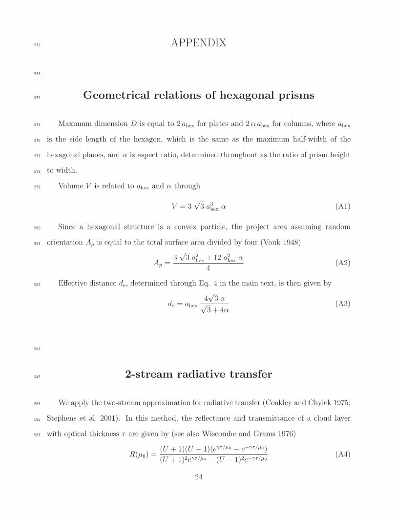
APPENDIX572
573
Geometrical relations of hexagonal prisms574
Maximum dimension D is equal to 2 ahex for plates and 2α ahex for columns, where ahex575
is the side length of the hexagon, which is the same as the maximum half-width of the576
hexagonal planes, and α is aspect ratio, determined throughout as the ratio of prism height577
to width.578
Volume V is related to ahex and α through579
V = 3√3 a3hex α (A1)
Since a hexagonal structure is a convex particle, the project area assuming random580
orientation Ap is equal to the total surface area divided by four (Vouk 1948)581
Ap =3√3 a2hex + 12 a2hex α
4(A2)
Effective distance de, determined through Eq. 4 in the main text, is then given by582
de = ahex4√3 α√
3 + 4α(A3)
583
2-stream radiative transfer584
We apply the two-stream approximation for radiative transfer (Coakley and Chylek 1975;585
Stephens et al. 2001). In this method, the reflectance and transmittance of a cloud layer586
with optical thickness τ are given by (see also Wiscombe and Grams 1976)587
R(µ0) =(U + 1)(U − 1)(eγτ/µ0 − e−γτ/µ0)
(U + 1)2eγτ/µ0 − (U − 1)2e−γτ/µ0
(A4)
24

and588
T (µ0) =4U
(U + 1)2eγτ/µ0 − (U − 1)2e−γτ/µ0
, (A5)
where µ0 is the cosine of the solar zenith angle and589
U =
√
1− ω + ω(1− g)
1− ω, (A6)
590
γ =√
(1− ω)[1− ω + ω(1− g)]. (A7)
At non-absorbing wavelengths (ω = 1), this simplifies to591
R(µ0) =τ(1− g)
2µ0 + τ(1− g)(A8)
and T = 1−R.592
The cloud layer can be embedded in a Rayleigh-scattering and absorbing atmosphere.593
Ignoring surface reflection and multiple scattering, the monochromatic upwelling flux F↑ at594
the top of atmosphere with a cloud layer whose top is located at optical depth τt is given by595
F↑ = F⊙ e−τt/µ0
∫ 1
0
R(µ, µ0) e−τt/µµ dµ, (A9)
where F⊙ is the monochromatic solar flux, µ is the angle of outgoing radiation and R(µ, µ0)596
is a bi-directional reflection matrix. To evaluate this integral, we use the approximations597
R(µ, µ0) = R(µ0) and598
∫ 1
0
µ e−τt/µ dµ ≈ e−τt/µeff , (A10)
where µeff = 1/√3, leading to599
F↑ = F⊙ R(µ0) e−τt(
1
µ0+ 1
µeff)
(A11)
Similarly the downwelling diffuse flux F↓ at the surface is given by600
F↓ = F⊙ T (µ0) e−τt/µ0 e−(τtot−τb)/µeff , (A12)
where τb is the optical depth level at the bottom of the cloud layer and τtot is the total601
optical thickness of the atmosphere excluding the cloud layer. Note that extinction from602
25

gaseous absorption and Rayleigh scattering within the cloud layer is ignored by A12. Cloud603
absorptance acloud is defined as604
acloud = (F⊙ −R(µ0)− T (µ0)) e−τt/µ0 . (A13)
For wavelength bands that include high spectrally variant absorption lines, the correlated-605
k distribution method (Lacis and Oinas 1991) is used.606
26

607
REFERENCES608
Auer, A. and D. Veal, 1970: The dimension of ice crystals in natural clouds. J. Atmos. Sci,609
27 (6), 919–926.610
Baker, B. and R. P. Lawson, 2006: Improvement in Determination of Ice Water Content611
from Two-Dimensional Particle Imagery. Part I: Image-to-Mass Relationships. J. Appl.612
Met. Climatol., 45 (9), 1282–1290, doi:10.1175/JAM2398.1.613
Baran, A. J., 2009: A review of the light scattering properties of cirrus. J. Quant. Spectrosc.614
Radiat. Transfer, 110 (14-16), 1239–1260, doi:10.1016/j.jqsrt.2009.02.026.615
Baran, A. J., 2012: From the single-scattering properties of ice crystals to climate prediction:616
A way forward. Atmos. Res., 112, 45–69, doi:10.1016/j.atmosres.2012.04.010.617
Baum, B. A., A. J. Heymsfield, P. Yang, and S. T. Bedka, 2005a: Bulk scattering properties618
for the remote sensing of ice clouds. Part I: Microphysical data and models. J. Appl.619
Meteor., 44 (12), 1885, doi:10.1175/JAM2308.1.620
Baum, B. A., P. Yang, A. J. Heymsfield, S. Platnick, M. D. King, Y. X. Hu, and S. M.621
Bedka, 2005b: Bulk scattering properties for the remote sensing of ice clouds. Part II:622
Narrowband models. J. Appl. Meteor., 44 (12), 1896–1911.623
Bohm, J., 1992: A general hydrodynamic theory for mixed-phase microphysics. Part I: Drag624
and fall speed of hydrometeors. Atmos. Res., 27 (4), 253–274, doi:10.1016/0169-8095(92)625
90035-9.626
Bohm, J. P., 1989: A general equation for the terminal fall speed of solid hydrometeors. J.627
Atmos. Sci., 46 (15).628
27

Born, M. and E. Wolf, 1999: Principles of optics. 7th ed., Cambridge University Press.629
Bryant, F. and P. Latimer, 1969: Optical efficiencies of large particles of arbitrary shape and630
orientation. J. Colloid Interface Sci., 30 (3), 291–304, doi:10.1016/0021-9797(69)90396-8.631
Chepfer, H., P. Goloub, J. Riedi, J. De Haan, J. Hovenier, and P. Flamant, 2001: Ice632
crystal shapes in cirrus clouds derived from POLDER/ADEOS-1. J. Geophys. Res, 106,633
7955–7966.634
Coakley, J. A. J. and P. Chylek, 1975: The two-stream approximation in radiative transfer:635
Including the angle of the incident radiation. J. Atmos. Sci., 32, 409–418.636
Edwards, J., S. Havemann, J.-C. Thelen, and A. Baran, 2007: A new parametrization for637
the radiative properties of ice crystals: Comparison with existing schemes and impact in638
a GCM. Atmos. Res., 83 (1), 19–35, doi:10.1016/j.atmosres.2006.03.002.639
Foot, J. S., 1988: Some observations of the optical properties of clouds. II: Cirrus. Q. J. R.640
Meteorol. Soc., 114 (479), 145–164, doi:10.1002/qj.49711447908.641
Francis, P. N., A. Jones, R. W. Saunders, K. P. Shine, A. Slingo, and Z. Sun, 1994: An642
observational and theoretical study of the radiative properties of cirrus: Some results643
from ICE’89. Q. J. R. Meteorol. Soc, 120 (518), 809–848, doi:10.1002/qj.49712051804.644
Fridlind, A., et al., 2012: A comparison of TWP-ICE observational data with cloud-resolving645
model results. J. Geophys. Res., 117, D05 204, doi:10.1029/2011JD016595.646
Fu, Q., 1996: An Accurate Parameterization of the Solar Radiative Properties of Cirrus647
Clouds for Climate Models. J. Clim., 9 (9), 2058–2082, doi:10.1175/1520-0442(1996)648
009〈2058:AAPOTS〉2.0.CO;2.649
Fu, Q., 2007: A new parameterization of an asymmetry factor of cirrus clouds for climate650
models. J. Atmos. Sci., 64 (11), 4140, doi:10.1175/2007JAS2289.1.651
28
Fu, Q. and K. N. Liou, 1993: Parameterization of the radiative properties of cirrus clouds.652
J. Atmos. Sci., 50 (13), 2008–2025, doi:10.1175/1520-0469(1993)050〈2008:POTRPO〉2.0.653
CO;2.654
Fu, Q., W. B. Sun, and P. Yang, 1999: Modeling of scattering and absorption by nonspherical655
cirrus ice particles at thermal infrared wavelengths. J. Atmos. Sci., 56 (16), 2937–2947,656
doi:10.1175/1520-0469(1999)056〈2937:MOSAAB〉2.0.CO;2.657
Garrett, T. J., P. V. Hobbs, and H. Gerber, 2001: Shortwave, single-scattering properties of658
arctic ice clouds. J. Geophys. Res., 106 (D14), 15 155–15 172, doi:10.1029/2000JD900195.659
Grenfell, T. C. and S. G. Warren, 1999: Representation of a nonspherical ice particle by a660
collection of independent spheres for scattering and absorption of radiation. J. Geophys.661
Res., 104 (D24), 31 697–31 709, doi:10.1029/1999JD900496.662
Guimaraes, L. and H. Nussenzveig, 1992: Theory of Mie resonances and ripple fluctuations.663
Opt. Commun., 89 (5), 363–369.664
Hess, M., R. B. Koelemeijer, and P. Stammes, 1998: Scattering matrices of imperfect665
hexagonal ice crystals. J. Quant. Spectrosc. Radiat. Transfer, 60 (3), 301–308, doi:666
10.1016/S0022-4073(98)00007-7.667
Heymsfield, A. J., A. Bansemer, P. R. Field, S. L. Durden, J. L. Stith, J. E. Dye, W. Hall,668
and C. A. Grainger, 2002: Observations and parameterizations of particle size distri-669
butions in deep tropical cirrus and stratiform precipitating clouds: Results from in670
situ observations in TRMM field campaigns. J. Atmos. Sci., 59 (24), 3457–3491, doi:671
10.1175/1520-0469(2002)059〈3457:OAPOPS〉2.0.CO;2.672
Heymsfield, A. J. and J. Iaquinta, 2000: Cirrus crystal terminal velocities. J. Atmos. Sci.,673
57 (7).674
29

Iaquinta, J., H. Isaka, and P. Personne, 1995: Scattering phase function of bullet rosette675
ice crystals. J. Atmos. Sci., 52 (9), 1401–1413, doi:10.1175/1520-0469(1995)052〈1401:676
SPFOBR〉2.0.CO;2.677
Kato, S., T. P. Ackerman, J. H. Mather, and E. E. Clothiaux, 1999: The k-distribution678
method and correlated-k approximation for a shortwave radiative transfer model. J. Quant.679
Spectrosc. Radiat. Transfer, 62 (1), 109–121, doi:10.1016/S0022-4073(98)00075-2.680
Key, J. R., P. Yang, B. A. Baum, and S. Nasiri, 2002: Parameterization of shortwave ice681
cloud optical properties for various particle habits. J. Geophys. Res., 107 (D13), 4181,682
doi:10.1029/2001JD000742.683
King, M. D., S. Platnick, P. Yang, G. T. Arnold, M. A. Gray, J. C. Riedi, S. A. Ackerman,684
and K.-N. Liou, 2004: Remote sensing of liquid water and ice cloud optical thickness and685
effective radius in the Arctic: Application of airborne multispectral MAS data. J. Atm.686
Ocean. Tech., 21 (6), 857–875, doi:10.1175/1520-0426(2004)021〈0857:RSOLWA〉2.0.CO;2.687
Korolev, A. V., E. F. Emery, J. W. Strapp, S. G. Cober, G. A. Isaac, M. Wasey, and688
D. Marcotte, 2011: Small ice particles in tropospheric clouds: fact or artifact? Airborne689
icing instrumentation evaluation experiment. Bull. Amer. Meteor. Soc., 92, 967–973, doi:690
10.1175/2010BAMS3141.1.691
Korolev, A. V. and G. Isaac, 2003: Roundness and aspect ratio of particles in ice clouds. J.692
Atmos. Sci., 60 (15), 1795–1808.693
Kristjansson, J., J. Edwards, and D. Mitchell, 1999: A new parameterization scheme for the694
optical properties of ice crystals for use in general circulation models of the atmosphere.695
Phys. Chem. Earth B, 24 (3), 231–236, doi:10.1016/S1464-1909(98)00043-4.696
Kristjansson, J. E., J. M. Edwards, and D. L. Mitchell, 2000: Impact of a new scheme for697
optical properties of ice crystals on climates of two GCMs. J. Geophys. Res., 105 (D8),698
10 063, doi:10.1029/2000JD900015.699
30
Lacis, A. A. and V. Oinas, 1991: A description of the correlated k distribution method700
for modeling nongray gaseous absorption, thermal emission, and multiple scattering in701
vertically inhomogeneous atmospheres. J. Geophys. Res., 96 (D5), 9027–9063, doi:10.702
1029/90JD01945.703
Lawson, R. P., E. Jensen, D. L. Mitchell, B. Baker, Q. Mo, and B. Pilson, 2010: Microphysical704
and radiative properties of tropical clouds investigated in TC4 and NAMMA. J. Geophys.705
Res., 115, doi:10.1029/2009JD013017.706
Lindqvist, H., K. Muinonen, T. Nousiainen, J. Um, G. M. McFarquhar, P. Haapanala,707
R. Makkonen, and H. Hakkarainen, 2012: Ice-cloud particle habit classification using708
principal components. J. Geophys. Res., 117 (D16), D16 206, doi:10.1029/2012JD017573.709
Liu, X., S. Ding, L. Bi, and P. Yang, 2012: On the Use of Scattering Kernels to Calculate710
Ice Cloud Bulk Optical Properties. J. Atm. Ocean. Tech., 29 (1), 50–63, doi:10.1175/711
JTECH-D-11-00034.1.712
Macke, A., M. I. Mishchenko, K. Muinonen, and B. E. Carlson, 1995: Scattering of light713
by large nonspherical particles: ray-tracing approximation versus T-matrix method. Opt.714
Lett., 20 (19), 1934, doi:10.1364/OL.20.001934.715
Macke, A., J. Mueller, and E. Raschke, 1996: Single scattering properties of atmospheric ice716
crystals. J. Atmos. Sci., 53 (19), 2813–2825.717
Mauno, P., G. M. McFarquhar, P. Raisanen, M. Kahnert, M. S. Timlin, and T. Nou-718
siainen, 2011: The influence of observed cirrus microphysical properties on shortwave719
radiation: A case study over Oklahoma. J. Geophys. Res., 116 (D22), D22 208, doi:720
10.1029/2011JD016058.721
McFarquhar, G. M. and A. J. Heymsfield, 1998: The definition and significance of an effec-722
tive radius for ice clouds. J. Atmos. Sci., 55 (11), doi:10.1175/1520-0469(1998)055〈2039:723
TDASOA〉2.0.CO;2.724
31

McFarquhar, G. M., P. Yang, A. Macke, and A. J. Baran, 2002: A New Parameterization725
of Single Scattering Solar Radiative Properties for Tropical Anvils Using Observed Ice726
Crystal Size and Shape Distributions. J. Atmos. Sci., 59 (16), 2458–2478, doi:10.1175/727
1520-0469(2002)059〈2458:ANPOSS〉2.0.CO;2.728
Mishchenko, M. I. and A. Macke, 1998: Incorporation of physical optics effects and com-729
putation of the Legendre expansion for ray-tracing phase functions involving δ-function730
transmission. J. Geophys. Res., 103 (D2), 1799–1805, doi:10.1029/97JD03121.731
Mitchell, D., 2002: Effective diameter in radiation transfer: General definition, applica-732
tions, and limitations. J. Atmos. Sci., 59 (15), 15, doi:10.1175/1520-0469(2002)059〈2330:733
EDIRTG〉2.0.CO;2.734
Mitchell, D. and W. Arnott, 1994: A model predicting the evolution of ice particle size spec-735
tra and radiative properties of cirrus clouds. Part II: Dependence of absorption and extinc-736
tion on ice crystal morphology. J. Atmos. Sci., 51, 817–832, doi:10.1175/1520-0469(1994)737
051〈0817:AMPTEO〉2.0.CO;2.738
Mitchell, D., Y. Liu, and A. Macke, 1996: Modeling cirrus clouds. Part II: Treatment of739
radiative properties. J. Atmos. Sci., 53 (20), 2967–2988.740
Mitchell, D. L., 1991: Evolution of snow-size spectra in cyclonic storms. Part II: Devi-741
ations from the exponential form. J. Atmos. Sci., 48 (16), 1885–1899, doi:10.1175/742
1520-0469(1991)048〈1885:EOSSSI〉2.0.CO;2.743
Mitchell, D. L., 2000: Parameterization of the Mie Extinction and Absorption Coefficients for744
Water Clouds. J. Atmos. Sci., 57 (9), 1311–1326, doi:10.1175/1520-0469(2000)057〈1311:745
POTMEA〉2.0.CO;2.746
Mitchell, D. L., A. J. Baran, W. P. Arnott, and C. Schmitt, 2006: Testing and Comparing747
the Modified Anomalous Diffraction Approximation. J. Atmos. Sci., 63 (11), 2948–2962,748
doi:10.1175/JAS3775.1.749
32

Mitchell, D. L., P. Rasch, D. Ivanova, G. McFarquhar, and T. Nousiainen, 2008: Impact750
of small ice crystal assumptions on ice sedimentation rates in cirrus clouds and GCM751
simulations. Geophys. Res. Lett., 35 (9), L09 806, doi:10.1029/2008GL033552.752
Neshyba, S. P., T. C. Grenfell, and S. G. Warren, 2003: Representation of a nonspheri-753
cal ice particle by a collection of independent spheres for scattering and absorption of754
radiation: 2. Hexagonal columns and plates. J. Geophys. Res., 108 (D15), 4448, doi:755
10.1029/2002JD003302.756
Neshyba, S. P., B. Lowen, M. Benning, A. Lawson, and P. M. Rowe, 2013: Roughness metrics757
of prismatic facets of ice. J. Geophys. Res., 118 (8), 3309–3318, doi:10.1002/jgrd.50357.758
Schlimme, I., A. Macke, and J. Reichardt, 2005: The Impact of Ice Crystal Shapes, Size759
Distributions, and Spatial Structures of Cirrus Clouds on Solar Radiative Fluxes. J. Atmos.760
Sci., 62 (7), 2274–2283, doi:10.1175/JAS3459.1.761
Stackhouse, P. W. J. and G. L. Stephens, 1991: A theoretical and observational study of762
the radiative properties of cirrus: Results from FIRE 1986. J. Atmos. Sci., 48 (18),763
2044–2059, doi:10.1175/1520-0469(1991)048〈2044:ATAOSO〉2.0.CO;2.764
Stephens, G. L., P. M. Gabriel, and P. T. Partain, 2001: Parameterization of Atmospheric765
Radiative Transfer. Part I: Validity of Simple Models. J. Atmos. Sci., 58 (22), doi:10.766
1175/1520-0469(2001)058〈3391:POARTP〉2.0.CO;2.767
Stephens, G. L., S.-C. Tsay, J. Stackhouse, Paul W., and P. J. Flatau, 1990: The relevance768
of the microphysical and radiative properties of cirrus clouds to climate and climatic769
feedback. J. Atmos. Sci., 47 (14), 1742–1754.770
Sulia, K. J. and J. Y. Harrington, 2011: Ice aspect ratio influences on mixed-phase clouds:771
Impacts on phase partitioning in parcel models. J. Geophys. Res., 116 (D21), D21 309,772
doi:10.1029/2011JD016298.773
33

Takano, Y. and K.-N. Liou, 1989: Solar Radiative Transfer in Cirrus Clouds. Part I: Single-774
Scattering and Optical Properties of Hexagonal Ice Crystals. J. Atmos. Sci., 46 (1), 3–19,775
doi:10.1175/1520-0469(1989)046〈0003:SRTICC〉2.0.CO;2.776
Um, J. and G. M. McFarquhar, 2007: Single-Scattering Properties of Aggregates of Bullet777
Rosettes in Cirrus. J. Appl. Meteor. Climatol., 46 (6), 757, doi:10.1175/JAM2501.1.778
Um, J. and G. M. McFarquhar, 2009: Single-scattering properties of aggregates of plates.779
Q. J. R. Meteorol. Soc, 135 (639), 291–304, doi:10.1002/qj.378.780
van de Hulst, H. C., 1957: Light scattering by small particles. Dover Publications, New York.781
van Diedenhoven, B., B. Cairns, A. M. Fridlind, A. S. Ackerman, and T. J. Garrett, 2013:782
Remote sensing of ice crystal asymmetry parameter using multi-directional polarization783
measurements Part 2: Application to the Research Scanning Polarimeter. Atm. Chem.784
Phys., 13 (6), 3185–3203, doi:10.5194/acp-13-3185-2013.785
van Diedenhoven, B., B. Cairns, I. V. Geogdzhayev, A. M. Fridlind, A. S. Ackerman, P. Yang,786
and B. A. Baum, 2012a: Remote sensing of ice crystal asymmetry parameter using multi-787
directional polarization measurements - Part 1: Methodology and evaluation with simu-788
lated measurements. Atm. Meas. Techn., 5, 2361–2374, doi:10.5194/amt-5-2361-2012.789
van Diedenhoven, B., A. M. Fridlind, A. S. Ackerman, and B. Cairns, 2012b: Evaluation790
of hydrometeor phase and ice properties in cloud-resolving model simulations of tropical791
deep convection using radiance and polarization measurements. J. Atmos. Sci., 69 (11),792
3290–3314, doi:10.1175/JAS-D-11-0314.1.793
Vouk, V., 1948: Projected area of convex bodies. Nature, 162 (4113), 330.794
Warren, S. G., 1984: Optical Constants of Ice from the Ultraviolet to the Microwave. Appl.795
Opt., 23 (8), 1206.796
34
Warren, S. G. and R. E. Brandt, 2008: Optical constants of ice from the ultraviolet to the797
microwave: A revised compilation. J. Geophys. Res., 113 (D14), D14 220, doi:10.1029/798
2007JD009744.799
Westbrook, C. D., 2008: The fall speeds of sub-100 micron ice crystals. Q. J. R. Meteorol.800
Soc., 134 (634), 1243–1251, doi:10.1002/qj.290.801
Westbrook, C. D., R. J. Hogan, and A. J. Illingworth, 2008: The capacitance of pristine ice802
crystals and aggregate snowflakes. J. Atmos. Sci., 65 (1), 206, doi:10.1175/2007JAS2315.803
1.804
Wiscombe, W. and G. Grams, 1976: The backscattered fraction in two-stream approxima-805
tions. J. Atmos. Sci, 33 (12), 2440–2451, doi:10.1175/1520-0469(1976)033.806
Wood, S. E., M. B. Baker, and D. Calhoun, 2001: New model for the vapor growth of807
hexagonal ice crystals in the atmosphere. J. Geophys. Res., 106 (D5), 4845, doi:10.1029/808
2000JD900338.809
Wyser, K. and P. Yang, 1998: Average ice crystal size and bulk short-wave single-scattering810
properties of cirrus clouds. Atmos. Res., 49 (4), 315–335, doi:10.1016/S0169-8095(98)811
00083-0.812
Xie, Y., P. Yang, K. Liou, P. Minnis, and D. Duda, 2012: Parameterization of contrail813
radiative properties for climate studies. Geophys. Res. Lett.814
Yang, P., L. Bi, B. A. Baum, K.-N. Liou, G. W. Kattawar, M. I. Mishchenko, and B. Cole,815
2013: Spectrally consistent scattering, absorption, and polarization properties of atmo-816
spheric ice crystals at wavelengths from 0.2 µm to 100 µm. J. Atmos. Sci., 70, 330–347,817
doi:10.1175/JAS-D-12-039.1.818
Yang, P. and Q. Fu, 2009: Dependence of ice crystal optical properties on particle aspect819
35

ratio. J. Quant. Spectrosc. Radiat. Transfer, 110 (14-16), 1604–1614, doi:10.1016/j.jqsrt.820
2009.03.004.821
Yang, P., G. Kattawar, G. Hong, P. Minnis, and Y. Hu, 2008: Uncertainties associated with822
the surface texture of ice particles in satellite-based retrieval of cirrus clouds - Part I:823
Single-scattering properties of ice crystals with surface roughness. IEEE Trans. Geosci.824
Rem. Sens., 46 (7), 1940–1947, doi:10.1109/TGRS.2008.916471.825
Yang, P. and K. Liou, 1998: Single-scattering Properties of Complex Ice Crystals in Terres-826
trial Atmosphere. Contr. Atmos. Phys., 71 (2), 223–248.827
Yang, P., K. Liou, K. Wyser, and D. Mitchell, 2000: Parameterization of scattering and828
absorption properties of individual ice crystals. J. Geophys. Res., 105, 4699–4718.829
Yang, P. and K. N. Liou, 1996: Geometric-optics integral-equation method for light scatter-830
ing by nonspherical ice crystals. Appl. Opt., 35 (33).831
Yang, P., Z. Zhang, B. a. Baum, H.-L. Huang, and Y. Hu, 2004: A new look at anomalous832
diffraction theory (ADT): Algorithm in cumulative projected-area distribution domain and833
modified ADT. J. Quant. Spectrosc. Radiat. Transfer, 89 (1-4), 421–442, doi:10.1016/j.834
jqsrt.2004.05.038.835
Yi, B., P. Yang, B. A. Baum, T. L’Ecuyer, L. Oreopoulos, E. J. Mlawer, A. J. Heymsfield,836
and K.-N. Liou, 2013: Influence of Ice Particle Surface Roughening on the Global Cloud837
Radiative Effect. J. Atmos. Sci., 70 (9), 2794–2807, doi:10.1175/JAS-D-13-020.1.838
36
List of Tables839
1 Average wavelengths (λa), and real (mr) and imaginary (mi) parts of the840
refractive index used in the reference calculations. Values of mr, mi (Warren841
1984; Warren and Brandt 2008) and λa are weighted by solar irradiance at the842
top of the atmosphere (TOA) within each wavelength band. Band edges are843
given in Table 1 of Kato et al. (1999), with bands 9–15 there corresponding844
to band 9 here. 38845
2 Coefficients ci,j used by Eq. 9 to compute coefficients li in Eq. 8. See also Fig.846
4, box 3. 39847
3 Coefficients qi,j of the sixth–order polynomial to compute coefficients p∆,i in848
Eq. 15. See also Fig. 7, box 4. 40849
4 Medians and inter-quartile ranges (within brackets) of relative errors in fluxes850
and absorptance owing to the proposed parameterization for several aspect851
ratio ranges. 41852
37

Table 1. Average wavelengths (λa), and real (mr) and imaginary (mi) parts of the refractiveindex used in the reference calculations. Values of mr, mi (Warren 1984; Warren and Brandt2008) and λa are weighted by solar irradiance at the top of the atmosphere (TOA) withineach wavelength band. Band edges are given in Table 1 of Kato et al. (1999), with bands9–15 there corresponding to band 9 here.
λa mr mi
[µm]0.256 1.3480 8.082·10−9
0.280 1.3407 6.751·10−9
0.296 1.3353 5.756·10−9
0.319 1.3307 4.878·10−9
0.335 1.3275 4.269·10−9
0.365 1.3231 3.420·10−9
0.420 1.3177 2.261·10−9
0.482 1.3140 1.742·10−9
0.598 1.3098 7.511·10−9
0.690 1.3071 2.445·10−8
0.719 1.3056 7.549·10−8
0.762 1.3065 3.834·10−8
0.813 1.3047 1.376·10−7
0.862 1.3038 2.330·10−7
0.926 1.3028 5.267·10−7
1.005 1.3014 1.724·10−6
1.111 1.2997 2.228·10−6
1.333 1.2955 7.335·10−5
1.562 1.2906 4.841·10−4
1.770 1.2837 2.627·10−4
2.051 1.2717 1.212·10−3
2.210 1.2629 3.064·10−4
2.584 1.1815 2.773·10−2
3.284 1.4310 2.719·10−1
3.809 1.3874 7.558·10−3
4.292 1.3473 1.639·10−2
38

Table 2. Coefficients ci,j used by Eq. 9 to compute coefficients li in Eq. 8. See also Fig. 4,box 3.
j c0,j c1,j c2,j
Plates
0 0.000527060 0.309748 -2.580281 0.00867596 -0.650188 -1.349492 0.0382627 -0.198214 -0.6744953 0.0108558 -0.0356019 -0.141318
Columns
0 0.000378774 0.390452 -2.368211 0.00463283 0.420040 1.076032 0.00593106 -0.0848059 -0.7299803 -0.00117167 0.0186601 0.232446
39
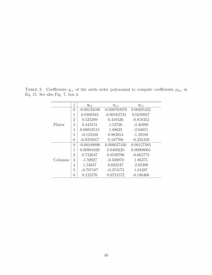
Table 3. Coefficients qi,j of the sixth–order polynomial to compute coefficients p∆,i inEq. 15. See also Fig. 7, box 4.
j q0,j q1,j q2,j
Plates
0 -0.00133106 -0.000782076 0.002054221 0.0408343 -0.00162734 0.02409272 0.525289 0.418336 -0.8183523 0.443151 1.53726 -2.403994 0.00852515 1.88625 -2.646515 -0.123100 0.983854 -1.291886 -0.0376917 0.187708 -0.235359
Columns
0 -0.00189096 0.000637430 0.001573831 0.00981029 0.0409220 0.009080042 0.732647 0.0539796 -0.6657733 -1.59927 -0.500870 1.863754 1.54047 0.692547 -2.053905 -0.707187 -0.374173 1.012876 0.125276 0.0721572 -0.186466
40

Table 4. Medians and inter-quartile ranges (within brackets) of relative errors in fluxesand absorptance owing to the proposed parameterization for several aspect ratio ranges.
Quantity all α 0.5 ≤ α ≤ 2 α ≤ 0.1 α ≥ 10Reflectance 0.69 (1.1)% 0.50 (0.52)% 1.4 (2.1)% 0.85 (1.0)%Transmittance 0.00 (0.74)% 0.00 (0.49)% -0.07 (1.26)% 0.09 (1.15)%Absorptance -1.9 (2.2)% -1.4 (0.61)% -2.7 (1.7)% -4.3 (3.3)%
41

List of Figures853
1 Single scattering albedo for compact hexagonal ice crystals as a function of854
effective distance (a) and absorption size parameter (b). Colors indicate dif-855
ferent wavelength bands. The red-grey line represents the exponential fit856
described in the text. The blue dashed line is the result using ADT. 45857
2 Similar to Fig. 1b, but for hexagonal plates (a) and columns (b) with various858
aspect ratios, as indicated by the colors. All bands listed in Table 1 with859
weak to moderate absorption (mi < 0.02) are included. Grey-red dashed lines860
indicate fits. 46861
3 Differences between the parameterized single scattering albedo for particles862
with an aspect ratio of unity and the calculated single scattering albedos for863
several plates (a) and columns (b) with various aspect ratios. Grey-red dashed864
lines indicate fitted log-normal functions as described in the text. 47865
4 Summary of the parameterization of single scattering albedo ω (box 4), with866
the absorption size parameter in box 1, parameterization of single scattering867
albedo for particles with aspect ratio of unity (ωα=1) in box 2 and the param-868
eterization of the relative difference between ωα=1 and scattering albedo for869
particles with other aspect ratios in box 3. The geometric optics approxima-870
tion for the extinction cross section is given in box 5. 48871
5 Parameterized single scattering albedo as a function of particle aspect ratio872
and absorption size parameter. 49873
6 Diffraction asymmetry parameter of hexagonal ice crystals with an aspect874
ratio of unity as a function of scattering size parameter. The grey dashed line875
represents the exponential fit described in the text. 50876
42

7 Summary of the parameterization of asymmetry parameter gtot (box 9), with877
parameterization of the diffraction asymmetry parameter in boxes 1–2, pa-878
rameterization of ray tracing asymmetry parameter at 862 nm in boxes 3–5,879
and correction factors for real refractive index and absorption in boxes 6–8. 51880
8 Ice crystal total asymmetry parameters at 862 nm as a function of distortion881
parameter for various aspect ratios. Dashed lines represent the fits described882
in the text. 52883
9 Parameterized total asymmetry parameters at 862 nm (top) and the differ-884
ences from the reference calculations (bottom). 53885
10 The refraction plus reflection asymmetry parameter of non-absorbing ice crys-886
tals as a function of real refractive index, relative to its value at 862 nm, or887
mr = 1.3038. Calculations for several plate aspect ratios are indicated by888
color. Dashed lines represent fits as described in the text with indicated fit889
parameters ǫ. 54890
11 (a) Relative differences between calculated total asymmetry parameters and891
those estimated by using Eq. 12 and the refraction plus reflection asymmetry892
parameter for non-absorbing particles (ω = 1). Calculations for different893
wavelength bands are indicated by colors. Filled circles represent compact894
particles (α = 1) and open diamonds indicate thin plates (α = 0.1). Only895
two aspect ratios are shown to reduce clutter. (b) Relative differences in the896
refraction plus reflection asymmetry parameter for particles with ω = 1 and897
values for particles with lower single scattering albedos. Red lines indicate898
fits for α = 1 (dashed) and α = 0.1 (dashed-dotted) as described in the text.899
(c) As in (a), but using the derived factors as described in the text to correct900
the refraction plus reflection asymmetry parameter for absorption effects. 55901
43

12 Absolute difference between parameterized and calculated single scattering902
albedos for several wavelength bands as indicated by colors. Circles, diamonds903
and squares indicate hexagonal columns, plates and compact hexagons with904
aspect ratio ratio of unity, respectively. 56905
13 As Fig. 12 but for asymmetry parameter. 57906
14 Relative parameterization errors in transmittance, reflectance and absorp-907
tance of uniform cloud layers. The box and whisker plots show median values,908
25th and 75th percentiles and full ranges of the errors in several transmittance,909
reflectance and absorptance bins. Cloud optical thicknesses range from 0.01910
to 100 and wide ranges of different size distributions, aspect ratios and distor-911
tion parameters are included, as described in the text. A solar zenith angle912
of 60◦ is assumed. Further details provided in text. 58913
15 Illustration of variations of up- (a & b) and down-welling (c & d) fluxes and914
cloud absorptance (e & f) as a function of aspect ratios and distortion (left)915
and as a function of aspect ratio and effective diameter (right). The cloud916
layer has an optical thickness of 4 and is embedded in a tropical atmosphere917
between 10 and 11 km. The solar zenith angle is 60◦. 59918
44

Fig. 1. Single scattering albedo for compact hexagonal ice crystals as a function of effectivedistance (a) and absorption size parameter (b). Colors indicate different wavelength bands.The red-grey line represents the exponential fit described in the text. The blue dashed lineis the result using ADT.
45

Fig. 2. Similar to Fig. 1b, but for hexagonal plates (a) and columns (b) with variousaspect ratios, as indicated by the colors. All bands listed in Table 1 with weak to moderateabsorption (mi < 0.02) are included. Grey-red dashed lines indicate fits.
46

Fig. 3. Differences between the parameterized single scattering albedo for particles withan aspect ratio of unity and the calculated single scattering albedos for several plates (a)and columns (b) with various aspect ratios. Grey-red dashed lines indicate fitted log-normalfunctions as described in the text.
47

ApProjected
area
VVolume
λWavelength
miImaginary
refractive
index
αAspect ratio
χabs =miV
λAp
1
ωα=1 = 1 − a0(1 − e−a1 χabs)
a0 = 0.457593 and a1 = 20.9738
2
∆ωα =l0
√
2π l2 χabs
exp
−
(ln χabs − l1)2
2 l22
li =3∑
j=0
ci,j logjα (ci,j in Table 2)
3
ω = ωα=1 + ∆ωα
4σe = QeAp
Qe = 2
5
Fig. 4. Summary of the parameterization of single scattering albedo ω (box 4), with theabsorption size parameter in box 1, parameterization of single scattering albedo for particleswith aspect ratio of unity (ωα=1) in box 2 and the parameterization of the relative differencebetween ωα=1 and scattering albedo for particles with other aspect ratios in box 3. Thegeometric optics approximation for the extinction cross section is given in box 5.
48
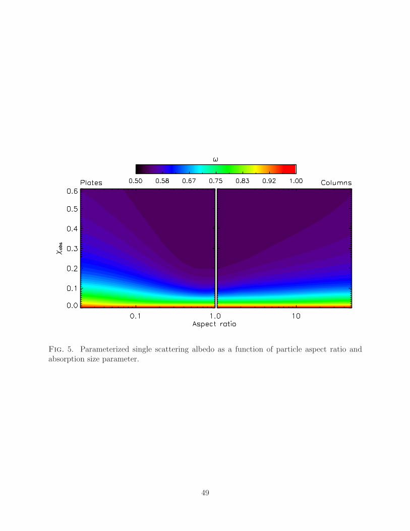
Fig. 5. Parameterized single scattering albedo as a function of particle aspect ratio andabsorption size parameter.
49

Fig. 6. Diffraction asymmetry parameter of hexagonal ice crystals with an aspect ratioof unity as a function of scattering size parameter. The grey dashed line represents theexponential fit described in the text.
50

Fig. 7. Summary of the parameterization of asymmetry parameter gtot (box 9), with pa-rameterization of the diffraction asymmetry parameter in boxes 1–2, parameterization ofray tracing asymmetry parameter at 862 nm in boxes 3–5, and correction factors for realrefractive index and absorption in boxes 6–8.
51
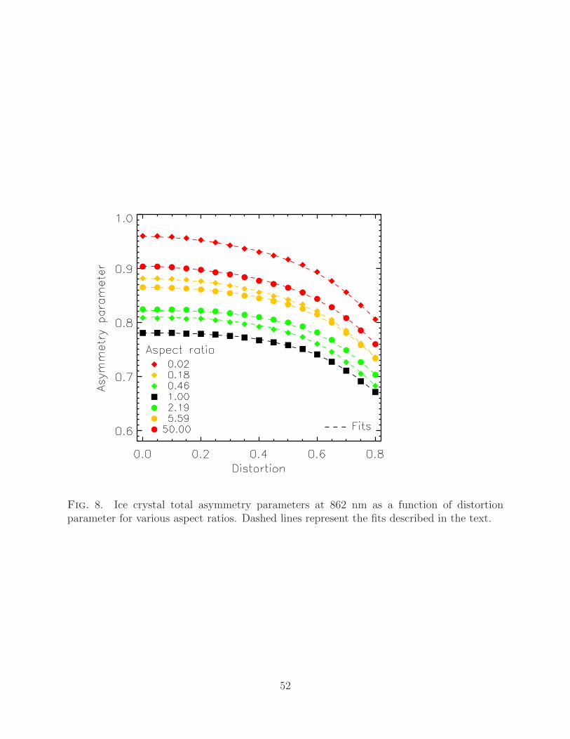
Fig. 8. Ice crystal total asymmetry parameters at 862 nm as a function of distortionparameter for various aspect ratios. Dashed lines represent the fits described in the text.
52

Fig. 9. Parameterized total asymmetry parameters at 862 nm (top) and the differencesfrom the reference calculations (bottom).
53

Fig. 10. The refraction plus reflection asymmetry parameter of non-absorbing ice crystalsas a function of real refractive index, relative to its value at 862 nm, or mr = 1.3038.Calculations for several plate aspect ratios are indicated by color. Dashed lines representfits as described in the text with indicated fit parameters ǫ.
54

Fig. 11. (a) Relative differences between calculated total asymmetry parameters and thoseestimated by using Eq. 12 and the refraction plus reflection asymmetry parameter for non-absorbing particles (ω = 1). Calculations for different wavelength bands are indicated bycolors. Filled circles represent compact particles (α = 1) and open diamonds indicate thinplates (α = 0.1). Only two aspect ratios are shown to reduce clutter. (b) Relative differencesin the refraction plus reflection asymmetry parameter for particles with ω = 1 and values forparticles with lower single scattering albedos. Red lines indicate fits for α = 1 (dashed) andα = 0.1 (dashed-dotted) as described in the text. (c) As in (a), but using the derived factorsas described in the text to correct the refraction plus reflection asymmetry parameter forabsorption effects.
55

Fig. 12. Absolute difference between parameterized and calculated single scattering albe-dos for several wavelength bands as indicated by colors. Circles, diamonds and squaresindicate hexagonal columns, plates and compact hexagons with aspect ratio ratio of unity,respectively.
56

Fig. 13. As Fig. 12 but for asymmetry parameter.
57

Fig. 14. Relative parameterization errors in transmittance, reflectance and absorptanceof uniform cloud layers. The box and whisker plots show median values, 25th and 75thpercentiles and full ranges of the errors in several transmittance, reflectance and absorptancebins. Cloud optical thicknesses range from 0.01 to 100 and wide ranges of different sizedistributions, aspect ratios and distortion parameters are included, as described in the text.A solar zenith angle of 60◦ is assumed. Further details provided in text.
58

Fig. 15. Illustration of variations of up- (a & b) and down-welling (c & d) fluxes and cloudabsorptance (e & f) as a function of aspect ratios and distortion (left) and as a function ofaspect ratio and effective diameter (right). The cloud layer has an optical thickness of 4 andis embedded in a tropical atmosphere between 10 and 11 km. The solar zenith angle is 60◦.
59