Embed Size (px)
Citation preview
Michael Sol Collection
EN GI N EERI N G-C 0 NT RACTI N G \r~o1. XXX\~. ~o. 14.
AND
in each group can be used, as desired. .;\t theHouston St. stairways the lamp standardswill have a single lamp only.
The total cost of the structure, includingengineering and all incidentals, will be about$570,000. The cost per square foot of flooris about $2.10, which is a remarkably lowfigure for a structure of this height. Thecontract was awarded to Corrigan, Lee &Halpin, of Kansas City, ~1o. The conc;retepiles are being put in place by the Gul f Concrete Construction Co. of Houston, Texas.The field work is being carried out under thesupervision of Hedrick & Cochrane, consulting engineers, Kansas City, 1\10., and J. F.Witt, county engineer. E. N. Noyes is resident engineer, representing the consulting engineers. The \vork was begun in October.uno, and is to be conlpleted by Dec. 1, HH 1.
other deformed bars of a type satisfactory tothe engineer. After the contract was let it\vas decided to use round corrugated rodsthroughout. The material for reinforcingbars is medium open hearth steel having anultilnate strength of from 60,000 to 68,000 Ibs.per sq. in.: an elastic limit not less than onehalf the ultimate strength; elongation of 22per cent; the capacity to bend cold 1800 to adiameter equal to the thickness of the piecetested without fracture on the outside of thebend.
Tri"ity River SpOIJ.-This span had foursteel girders connected by steel cross girders.i\ II metal work is to be encased in concrete.The steel girders carry in direct compressionthe horizontal thrust of the adjacent archspans. This thrust is carried into the bottonlflanges of the girders by means of special cast
II EAR T H
steel shoes, shown in Fig. 7. The unrightportion of the shoe bears against the concreteof the pier on one side and against the caststeel wedge on the other, the wedge beingdriven between the cast steel shoe and theend of the bottom flange angles. The girdersare otherwise of the ordinary type of construction and the material specified is mediumsteel except for' rivets, which are to be of softsteel.
Lightiug Sysle",.-At each pier 011 eitherside there will be a cement lamp standard onwhich are to be placed three 40-c. p., ,50-wattseries Tungsten lamps. Each lamp will beencased in a heavy 10-in. R. I. glass globe.The wiring system is to be so arranged thatthe center light on each post \vilt be on onecircuit and the two side lights on anothercircuit, so that either one, two, or three lights
ROCK SEC T I o€]Methods and Some Costs of the Con
struction of the St. Paul PassTunnel.
BY K. C. WEEDIN, MEM. A. S. C. E.·The St. Paul Pass tunnel is on the line of
the Chicago, Milwaukee & Puget Sound Ry.where the latter crosses the Bitter Root rangeof nl0untains on the l\lontana-Idaho stateline. It is 8,750 ft. long; 3,412 ft. being in~1ontana and 5,338 ft. in Idaho. The summitgrade in tunnel is elevation 4,169 ft. at a distance of 3J)20 ft. west of the east portal andthis point is 1,020.7 ft. below the surface. Thegradient is 0.2 per cent in both directionsf rom the summit. The location lies in a zoneof extremely great snow fall, possibly the~reatest in the United States: the actual fallduring the winter of 1!)07-08 being 33 ft. 4ins. Fortunately there is little wind.
Construction was begun Jan. 18, 1907, and
Fig. 1-Looking East from Summit alongTanCient, St. Paul Pass Tunnel.
was conlplett.-d ~1arch 4, IHoH. The ,,·ritera~~ttnleJ char~c for the ron1pany on Dec. G.1~'o7, or abollt one year after the \\'ork was~tartl'd. w
The C.. ~f. & P. S. Ry. practically parallels;and lies near the :\orthern Pacitic froln ~l lSIo\"\1la ttl Taft, ~'1()nt.; there tht.·y diverge, the
·c 'lIn~tnJ('tion ~\Ipf'ril1tf'll(l(,Jlt for .T. G. ""hUeI\: ('/I. 11\1".. r;JI~i 11t"'I"~ and Contractor:.;, 4:l-4~
I-:,\;,'hangf' PISI(·". N.'\\" York. ~. Y.
f orrner bearing to the southwest and crossingthe range into the valley of the North Fork,a tributary of the St. Joe River.
Ta ft being the nearest point to the tunnelon an operated railroad, 2.S miles distant, itwas decided to locate the power house there,g-enerate the electricity and transmit it tosttbst~tions, one at each end of the tunnel.There were two alternate propositions, bothhaving the main power station located nearthe east portal. One provided for the construction of a railroad, which would necessarily be on a steep grade, from Taft to theeast portal. This would be difficult and expensive to operate on account of both gradeand snow. The other was to team all machinery, fuel and supplies from Taft to thepo\ver house. The cost of either would havebeen greater and the probability of uninterrupted service less than that of the oneadopted.. .~ wagon road \\"a's constructed from Taft
across the range at great expense, over whichall supplies, nlachinery, timber, etc., were .transported both for the west end of thetunnel and for the grading and bridge workon the 'west slope.
This road required a great deal of attention.The average traffic over it was about 100 fourhorse teanlS per day and the maximum about160 four-horse teanlS. About 60 men \vererequired in sumlner to keep the road open.and about t\vicc that number 'were requiredin winter and spring. These men \vere stationed in three canlps along the road, one ateach portal and one at the sumnlit. Theroad was about 4% Iniles long and the sunlJnit was about 1,000 ft. above the portals.Fresh snow \vas attacked with a steel loggingplow pulled by 24 horses, then a aO-horse\\'ooden wedge plow \vas used and the work\vas tlnally finished \\,ith shovels. In spiteof this work the road bed \vas steadilv elevatcd during the winter until it was well upto the roofs of the camp houses.
During the winter of 1907-08 a cablewayone ll1ile long- \\'as built from the east portalto the sUJlunit. This cablewav was driven bva 30-hp. 1l10tor. Supplies, hiel, tinlher, etc:,\\'ere teatned f ronl Ta ft to the lo\\"er terminalnear east portal, carried on thc cable\\'ay tothe sumnlit, there transferred to wagons andhaul('d dO\\'n the \\"est slope. This 11lethodobviated the long, heavy teanl haul up theJlloltl1tain and greatly lessencd the tinH.-.
Tht, Jllain Po\\"('r station equiplncnt (,'011
-.istecl of the fol1<nvillR itenlS:6 ]flO-hp. AllUM high pressure tubular boilers,
H,·t up in hatterles of two.2 Blnk«" SxflxlO-ln. boiler feed pumps.2 }4~alrhl:lnk~-:\'lorse 5%x3%x5-ln. boiler feed
pUlnp.Blakt' 14x7lhx12-ln. underwriters nre pump,
nonnul ('apndty 500 gals. per Ininutp.1 Blakt, 14x22x24-1n. air pump and jet con
dptlser.~ 20x4S-ln. Corliss engines.1 14x28x~O-in. tandem cOlnpound l\tcEwen en
Klru' direct connected to a 200-kw. ~l-lJhu~e.fW-cyd('. ~.~OO-volt generator.
17x22-ln. A tIas enKlne.lOxlG-ln. At1~s enKlne, driving ~xciters.
2 200-kw. 3-phase. 2,200-volt. 60-cycle.. G. E.generators belted to the Corliss engines.
1 200-kw. 3-phase. 2,200-volt, 60-cycle, engin~
type', Westinghouse generator, direct connected to McEwen engine. A 17JAt-kw. 125volt Westinghouse exciter was belted to thl~generator.
35-kw. 125-\"olt G. E. direct connected generator, used for exclte'r.
3 250-k\\P. 2,200 to 6,600-volt, 60-cycle transformers-oll cooled.
3 Sets of 6.600-vott mulUKap llghtnlng arresterswith choke colIs and all necessary switchboard panels. connections. volt meters. circuit breakers, etc.
The machine shop equiplnent' was as follows:1 24-ln. x 14-ft. New Haven heavy duty engine
lathe.1 Four-jaw chuck. 16-ln. diameter.1 20-ln. Hoefer back geared drill press fitted
for No. 3 drill soeket.1 30-ln. 'Vallcott & 'Vood geared shaper, ex
tended base and counter shaft.1 No. 96 Forbes belt and hand driven pipe lna
chine with dies from 1 In. to 6 Ins. withcuttln~ off attachment.
1 Blacksmith outfit complete.
Fig. 2-View Showing Completed TimberLining of St. Paul Pass Tunnel.
(Large Pip(~ 1n Roof is Ventilating Pi})tl. ~lnall
Pipe is High Pn'ssure Line.)
I'he power station \vas protected by a good~ravity \\"ater system in addition to that a fforded by fire PUJ11p. The capacity of plant'was ,50 kw. and the alternating current wascarried to the suh-station at each end of th<tunnel-:.!lh Iniles to the east end and 4~
to the \\'l'~t etld- -o\'er a translnission line of
Michael Sol Collection
·i\pril S. 191 I. EN GI N EERI N G-CO NT RACTI N G
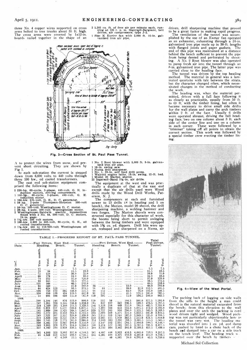
Fig. 4-View of the West Portal.
The packing hack of lagging on side wallsfronl the sills to the height a rnan couldshoveI IS the natural material excavated f ronlthe hench: fronl this elevation to the \\'al1plates and oyer the arch tht? packitl!{ IS cordwood driven tight and wedged. \Vood packing ,vas not particularly objectionable here asthe tunnel ,vas verv \\'ct. The headin~ 111a
terial '\'as sho\'clec( into 1 Cll. yd. end' dunl})cars. pushed hy hand to a chute hack of thehcnch 3.d dunlped into a car on a side trackon the lH.'nch level. The· headinR track \\.,supported over th.e 1)ench hy tilnhcrs
driven, drill sharpening 111achine that pro\'eclto be a great factor in making rapid progress.
The ventilation of the tunnel was acconlplished by the use of an Exeter fan operatedas an exhauster, exhausting through a 24-in.~al\'anized iron pipe nlade up in 30-ft. lengthswith flanged joints and paper gaskets. Theend of this pipe ,vas maintained at a distancehehind the bench sufficient to prevent the pipefrom being dented and perforated by shooting. .A No. 2 Root blower was also operatedto putnp fresh air into the tunnel through an8-in. galvanized iron pipe. The latter pipe \vascarried close to the heading face.
The tunnel \vas driven by the top headingInethod. The 111aterial in general was a laminated quartzite \\"ith talc between the strata,but the character changed often. which necessitated changes in the tnethod of conductingthe \\·ork.
rrhe head ing ,vas, \V hen the tnaterial pernlitted, driven \vith a full face following itas closely as practicable, usually from 50 ft.to 0.0 ft. with the timber lining, but often ithecame necessary to drive small side dri ftsfor the wall plates and carry the arch timberswithin 2 ft. of the face. Usually G drillswere operated abreast. driving the full heading face, 'two on one column about 3 ft. eachside of the center line and one on a columnin each corner. These were followed by a"trimlner" taking off all points to obtain thecorrect section. This \vork was followed bya special tinlber crew erecting the timber lining.
-;
"~7.5!~.5a;).O89.0
126.0172.5233.0293.040;'.:;598.;,763.:1963.;)
1.291.01,767.i')2.?31.02.'0:3.n3.26R.;'3.8:13.r.4.::J~S.;j
~.~lQ.~" .._,6;).,)6,146.')6.877.;-)7.499.u
S.25~.58.706.;;S.750.0
flSO.;)731.:;621.S
7;)~.!)
4:.4.043.5
~oE
327.5476.fl463.:,4.2.0f)65.fi58~,.0
;)3:'.0621.:'
,. r:...)
11.:':36.03-1.037.046.:,60.560.0
112.11193.016~,.O
200.0
3~.O
7G.0121.:;196.~
301.0r>39.ii'!ll.r.
],O~;).;)
1.321.:11.642.;:;~,~4~.;,_..,1 ... 02.GO;,.:'2,S!h).0a.287.53,G8S.5
13.019.044.04[..573.0
~cE
J04.fl238.52j2.0234.0~96.0
321.0:;07.0362.fi293.ii~84.;)
:;~l7 .5301.0
. '24~4606ri3910
1,2:!:'1.:14-1l,!l;j9~,~9~
2.6~4
3.1613,46;J
2 1,205 cu. ft. of free' air per minute each, running at 135 r. p. m. Ingers~ll... Sargeant. beltdrh'en, air cOlnpresBors, type J -2.
StzP. K Exetp.r fan with 2,000 ft. 16-ln. galvanized Iron air pipe.
1 No.2 Root blower with 5,000 ft. 8-ln. galvan-ized Iron air pipe.
1 16-ln. swing saw.1 Numa drill sharpener.1 No. I, 20-ln. selt' feed drill pre·ss.1 Walcott engine lathe, IS-In. swing, 12-ft. bed.1 Model 20 Marton shovel.25 Ingersoll-Rand 3~-ln. air drills.
The equipment at the "'est end was practicaHy a duplicate of that at the east endexcept that the air drills used were Wooddrills Inade by the Wood Drill Works, Paterson, N. ].
The compressors at each end furnishedpower to 13 drills (8 in heading and [) onbench), the Marion, model 20 shovel, the drillsharpening machine, a \ve lding hamnler andtwo forges. The Marion shovels were constructed especially for this character of work,the booms being short to permit s,vingingbetween the lining timbers and were equippedwith lJA. cu. yd. dippers. Drill bits were upset. reshaped and sharpened on a Numa. air
261SSS911~0
3~:; 4.097 44~ 3,913 416.5 4,005.0104 4,201 40~ 4.:~21 2;;6.04,261.0
40 4,361 20.0 4,281.0
l:i9 55~ 50~R;, 8:1'; 192:!s6 1,1:!3 21R:!'i;, 1,39" 193329 1,727 263:J:t3 ., Of,f1 30929;) 2::1;;~ 319:no 2.G6i') 41:-,254 2.919 333:!:!7 3.14:~ ~H2
~.;~ 3,·n.. ;j~7
2!)S 3.'1:! 30J
Total---Fp~tDriven, ""est End.-- Feet Driven.
H ending. Bench. Tunnel. Tunnel.-
....:
4,?)-1~.!)
4. i-If).;)4.770.0
19.0j5.089.0
l:!t;.O172.;)213.02So.()3j~t;;
;):!~.;i
64:!.0767.0
990.01,228.01.'l~~.~l,6,I. a],947.02,:!11. (I
:!.439.02,G9S.02.!l60.03,2;,6.03,[,90.04,211.;:')
7.a11.;)36.0:14.037.046.:.60.f)47.093.;)
295 149.0434 119.S630 1~3.0
876 :!23.01,10:-, ~a8.0
1.~,~~ 211.51,.,_ I 2:~S.O
l.S2:' 269.52.1;'0 26-1.02.3G7 22S.02.5j7 ~59.o
::!,77fi :?6:!.O3.?!! 2H6.03,.~ I;) 3~-t.O
3,6f,9 320.5
3,9n2 337.04. :J 42 1!l~ .I)4.3S~l :!:t5
38110178202345466560624 133750 172850 139904 196
1,104 :?4(l1,351 2291,569 20;)1.82R 217~,069 2982,:!72 32G:!,521 20i2,839 :WU3,145 :!l~
3,·165 ~i2
3,805 3284,162' 284
",503 3334.549 3fiO
47
three No.4 copper wires supported on crossarnlS holted to tree trunks about :35 ft. high.1"he cross arrns ,vere covered hy Ix12-in.hoard~ nailed together in the shape of an
:\ to protect the \vires from snow, and prevent short circuiting. They are ShO\\'l1 byFig 1.
:\t each sub-station the current is stepped<lown from 6,600 volts to 440 volts throughthree 100 kw., oil cooled transfortllers.
The east end sub-station equipnlent conlprised the following items:2 220-hp. eO-cycle, 3-phase, 440-\'olt. G. E. in
duction motors, driving compressors.1 100-l1p., 60-cycle, 3-phase, 440-volt, G. E.
induction motor.100~kw. 575-volt, G. E., D. C. generator.50 hp. . 2-pole Thompson-Houston 500-volt
D. C. generator.50-hp. 500-\'01t 'Vestlnghouse D. C. motor.
I 30-hp. 4-pole, 500-volt Westinghouse motor.2 Westtnghouse-Baldwln electric locomotives
fitted with 2 No. 64, 500-volt. D. C. motors,24-in. gage.
2 7 J,2 - kv;. 500 volt motors.3 l00-kw. 6,600 to 440-volt, 60-cycle, G. E., oil
cooled transformers.:t 7*-kw. 440 to 110/220-volt Westinghouse 011
cooled transformers.
TABLE I.-PROGRESS REPORT OF ST. PAUL PASS TUNNEL.
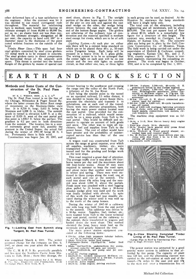
Fig. 3-erols Section of St. Paul Pasa Tunnel.
.c~oE
------·Feet Driven, East End.·Date. Heading. Bench. Tunnel.
.. -~
Jan ViFeb. 23Mar. 7:!_o\pl'li 68May 74Jun~ 93July 121Au~ 94Hep-t. 64Oct 126Nov 100[)P('. 54
1908.Jan 200Feb 247Mar. . 218Apr'iI 259May ~"1.Tun~ 203..Tuly 24!)Au~ 31SS~pt_ 306()et.......•... 320Xov 34{J])e('. . 357
1909..Jan. . 341F~b. 461\-I~r.........••.
Michael Sol Collection
390 ENG I NEE R IN G - C O-N T RAe TIN G \lo1. XXX\'. Xo. 14.
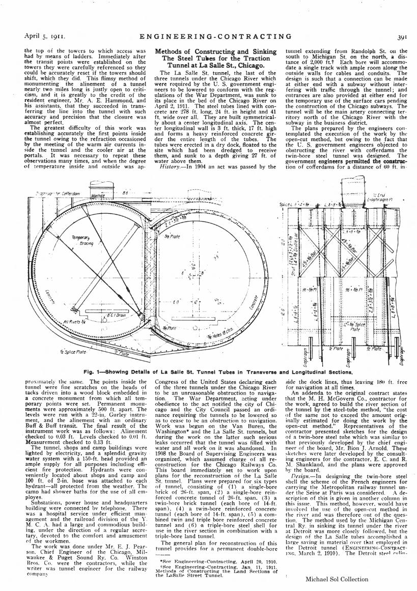
Fig. 6-West End Camp Buildings, St. Paul Pass Tunnel.
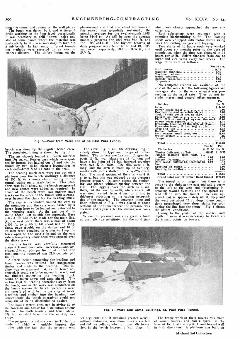
Fig. 5-View from West End of St. Paul Pass Tunnel.
also more closely approached the true circular arc.
Both substations \vere equipped with acOlllplete blacksmithing outfit. The framingsheds were equipped \\'ith motor drivcn swing5a\\'S for cutting \\redges and lagging.
Two shifts of 10 hours each \vere workeduntil about six months prior to the date ofcotnpletion, when the time \\'as changed to 11hours per shift. Shi fts changed from day tonight and vice versa every two \veeks, The\vage rates ,,'ere' as follows:
For 10 hrs.Shift bosses $4.76~'1achine runners......................... 3.76~fachlne helpers............. . . . . . . . . . . .. 3.26Inside laborers %.75Outside' laborers. . . . . . . . . . . . . . . . . . . . . . . .. 3.25(;arpenters .............• . . . . . . . . . . . . . . .. 4.00
No cOlnpletc records are available of thecost of the work but the following figures areaverages taken on the work when i.t was proceeding at the usual rate. They do not inf'lude interest and genera] office expenses.
PerDriving. Un. ft.
lMlbor $ 84.6~
Power house labor ,................ 7.00Engineering and superintendence......... 3.00Coal. 25 tons per 24 hra. at $2.50 ..... :.... 4.1lFrelght on coal........................... 8.20-Plant, 500/0 of cost chgd. against the work 15.00Power house repaIrs...................... 8.75Dynamite heading, 271bs. 60% at 16~c... 4.C6Dynamite bench, 23 Ibs., 40% a.t 12c...... 2.7'Caps and fuse............................. 1.10-Rubber clothes............................ 4.12Drill repairs, small tools, etc.............. 11.16'Vater s)pstem............................. .16Camps 1.10
Tota I $16C.14Per M. Per
Timbering. ft. B. M. lin. ft.Timber delivered at Taft.....•••.. $18.60 $ 1.16Timber teaming from Taft, 2%
miles , . . . . . . . . . . . 4.00 2.00Timber framing................... 4.50 %.16Cord wood: cutting $2, teaming $2 C.ot .40Iron .........••...•.........•........... .4«)Erec tlng on bench...................... 2.00Erecting in heading..................... 2.$5
TotaJ $ 18.66Grand total cost of timber lined tunnel $173.!~
'fhe tunnel is on tangent, but there is acurvc to the right at the east end and a curveto the left at the \vest end (stationing increasing toward Seattle) and the spirals extend 20 ft. into the tunnel. The east approach cut is approximately 50 ft. deep andthe west cut about 75 ft. deep; these conditions necessitated very short sights for producing the linc into the tunnel. Fig. 4 showsthe natural conditions.
Owing to the profile oi the surface and(lepth of sno\v it \\'as necessary to locate aUthe transit points on to\\·ers.
The frallle \vork of these to\\-ers was lnad~
of round tilnhers and had a spread at thehase of ];) ft. at the top (1 ft. and hraced wellin hoth din.'ctioJ1s. A pI tTQrnl "'as huilt on
phenomenal and that the effort to maintainthis record was splendidly sustained; themonthly average for the twelve-month 1908,being 544.6 ft. .As will be seen the averagemonthly progress for 1907 was 80.8 ft. andfor 1908, 544.G ft. The highest records ofdaily progress \\:,ere Nov. 17, 18 and 19, 1908,and were, respectively, 23.,l ft., il:!.:i ft., and2~ .•) ft.
The view, Fig. 2, a110 the drawing, Fig. 3,clearly show the type and design of timberlining. The timbers are 12xI2-in. Oregon fir:posts 16 ft.: wall plates are 18 ft. long andhave a lap joint of 12 ins. fastened togetherwith two %-in. bolts. The sills were 4 ft.long, and the arch is made up of fi\'e segments with joints slotted for a %x2~x12-in.
key. The usual spacing of the ribs was 4 ft.c. to c., but this was reduced as the pressurebecame greater. In some places the timbcring was placed without spacing between theribs. The lagging over the arch is 4: ins.thick, but that on the walls, where any at allwas used, varied from 4 ins. to 2 ins. inthickness according to the caving propensities of the material. The concrete lining andfloor indicated in Fig. 4 was placed at thosesections of the tunnel where the pressure was"reatest and a year after the driving \vas COIllpleted.
Where the pressure \vas very great, a builtup arch rib \\'as substituted for the solid tim-
her s('gillental rih_ It sustained greater weightwithout distortion, was nlore quickly e"l~rtl'(l
and did not collapse when an unusually hea \'yshot in the hrl1ch lo\\·ert'<1 a \\'all plate. It
ning the tunnel and resting on the wall plates.The bench was driven by 4, and at times, 5
drills working on the floor level: occasionallyit was necessary to drill "down" holes andalso at some places \vhere the nlaterial wasparticularly hard it \vas necessary to take outa sub bench. In fact, many different tunneling methods \vere resorted to, as circumstances dictated. The tinlher lining on the
bench was done by the regular bench crew.The completed lining is shown by Fig. 2.
The air shovels loaded all bench materialinto 1JAt cu. yd. Peteler cars which were spotted by horses, but hauled out of and into thetunnel by two 15-hp. electric locomotives ateach end-from 8 to 11 cars to the train.
The heading muck cars were run out on aplatform over the bench workings a distanceof 150 ft. to a muck chute leading to thetunnel trains on a track belo\v. This platform was built ahead as the bench progressedand new chutes were added as required. 111front of the bench were two narrow gagetracks on the sides of the tunnel with a erosso,'er beyond the chute for the heading muck.
The electric locomotive hauled the cars tothe crossover and the cars were hauled by ahorse from here to be loaded and returned tothe outgoing track. At the east portal thedump began just outside the approach: ~erea 60-ft. fill had to be tnade for the Inaln hue.At the west portal there was a haul of about2,500 ft. to a 70-ft. fill about 600 ft. long.Snow gave trouble on the dumps and 10 or12 men were required in winter to keep thetrack open on the west side and on the eastside a temporary snow shed \vas erected overthe dinky track.
The overbreak \vas carefully measured('very 8 ft.-oftener when necessary-and averaged ~.H4 cu. yds. per lin. ft. of tunnel. Thetotal Quantit)· removed was 21.5 cu. yds. perlin. ft.
A track incline connecting the headinJ.?; andhench tracks was utilized for transportinRtimber and tools to the heading. This incline \\'as so arranged that, as the bt~nch advanced, it could easily be moved forward, andthe timbers supporting the headin~ trackcould be taken down and used ahead. Theincline kept all heading operations away f rOlllthe bench, and as the \\'ork was conducted onthe honus svstClll the bench operations \\'erl'not interfered with hy the carryinR of tuols.1l1achines and tinlher into the heading, andc011seQuently the bench operatives could notrnlllplain of brin~ discrinlinated aRainst.
The h011US systenl consisted in ~ving $:! to1he forenlan and $1 :! .....O for distribution anlonJlthe Tuen for hoth ht'ading and hcnch aho\'t.,:P6 ft. per shift hascc1 on the nlonthly ;\v<.'ra~e.
The pruRress rrC'on} is shown in Tahle I, aiIHl~' of which will quickly inlpr('ss the;:der with tIl(' fact that the prn~r('s" "'as
Michael Sol Collection
.~pril 5, 191 I. EN GI NEE R IN G-C 0 NT RACT I N G
the top oi the towers to \\"hich access washad by nleans of ladders. Immediately afterthe transit points \vere established on thetowers they were carefully referenced so theycould be accurately reset jf the towers shouldshift, which they did. This flimsy method oftllOnuInenting the alinement of a tunnelnearly two miles long is justly open to criticisnl, and it is greatly to the credit 0 f theresident engineer, ~fr, l\, E. Hammond, andhis assistants, that they succeeded in transferring the line into the tunnel \vith suchaccuracy and precision that the closure wasalmost perfect.
The greatest difficulty of this \vork \vas~stablishing accurately the first points insidethe tunnel owing to the refraction occasionedby the meeting of the warm air currents in~ide the tunnel and the cooler air at theportals. I t was necessary to repeat theseobservations many times, and when the degreeof t~mperatl1re inside and outside was ap-
Methods of Constructing and SinkingThe Steel Tu.es for the Traction
Tunnel at La Salle St., Chicago.The La Salle S1. tunnel, the last of the
three tunnels under the Chicago River whichwere required by the U. S. government engineers to be lowered to conform with the regulations of the War Department, was sunk toits place in the bed of the Chicago River onl\pril 2, lUll. The steel tubes lined with concrete are 278 ft. long, 24 ft. in height and 41ft. wide over all. They are built symmetrically about, a center longitudinal axis. The center longitudinal wall is 3 ft. thick, 17 ft. highand forms a heavy reinforced concrete girder the entire length of the tubes. Thetubes were erected in a dry dock, floated to thesite which had heen dredged to receivethem, and sunk to a depth giving 27 ft. ofwater above them.
History.-In 1904 an act was passed by the
tunnel extending f ronl Randolph St. 011 thesouth to Michigan St. on the north, a distance of 2,000 ft. tEach bure will accommo·date a single track with ample room along theoutside walls for cables and conduits. Thedesign is such that a connection can be Inadeat either end with a subwav without interfering with traffic through the tunnel; andentrances are also provided at either end forthe temporary use of the surface cars pendingthe construction of the Ch icago subways. Thetunnel \vill be the main artery connecting territory north of the Chicago River with thesubway in the business district.
The plans prepared by the engineers contetnplated the execution of the \vork by thl'open-cut method, but o\\,ing to the fact thatthe U. S. government engineers objected toobstructing the river with cofferdams thetwin-bore steel tunnel was designed. Thegovernment engineers permitted the CODitruction of cofferdams for a distance of 00 ft. in-
proxlInately the sanlt:. The points inside thetunnel were fine scratches on the heads oftacks driven into a wood block etnbedded ina concrete monument from \vhich all telnporary points were set. Permanent monuments "'ere approximately 500 ft, apart. Thelevels were run with a 2~-ill. Gurley instrument, and the alinement with all ordinaryBuff & Buff transit. The final result of theinstrument \vork was as follo\vs: .A.1inelnentchecked to 0.03 ft. Levels checked to 0.01 it.Measurement checked to 0.13 ft.
The tunnel. shops and camp buildings \verelighted by electricity, and a splendid. gravity,water system \vith a l50-ft. head provided anample supply for all purposes including efficient fire protection. Hydrants \vere conveniently located about shops and canlp and100 ft. of 2-in. hose was attached to each,hydrant-all protected from the weather. l'hecamo had sho\ver baths for the use of all employes.
Substations, po\ver house and headquartersbuilding \vere connected bv telephone. Therewas a hospital service under efficient man3~ement and the railroad division of the Y.M. C. :\. had a large and conlnlodious building, under the direction of a regular secretary, devoted to the conlfort and amusementnf the "'orkmen.
The work was done under ~Ir. E. ]. Pearson. Chief Engineer of the Chicago, Milwaukee & Puget Sound Ry. Co. \VinstonBros. Co. \\fere the contractors, \vhile thewriter was tunnel enJlineer for the raihvay('onlpany
Congress of the United States declaring eachof the three tunnels under the Chicago Riverto be an unreasonable obstruction to navigation. The War Departnlent, ~cting underobedience to the act notified the city of Chicago and the City Council passed an ordinance requiring the tunnels to be 10\\'ered soas to cease to he an obstruction to navigation.Work \vas begun on the Van Buren, the\Vashington* and the La Salle St. tunnels, butduring the work on the latter such seriousleaks occurred that the tunnel was filled with\vater and all \vork on it \\'3S abandoned. In1908 the Board of Supervising EnRincers wasorganized, which assumed charge of all reconstruction tor the Chicago Raih,'ays Co.This board immediately set to \vork uponplans for the reconstruction ot the La SalleSt. tunnel. Plans \vere prepared for six typesof tunnel, consisting of (1) a single-borehrick of ~f)-it. span, (2) a single-bore reinforced concrete tunnel of 26-ft. span. (3) at\vin-hore hrick tunnel (each bore of 14-ft.span) , ( 4) a twin-bore rein forced concretetunn~l (each bore of 14-ft. span), (.~) a combined twin and triple bore reinforced concretetunnel and (6) {l triple-bore steel shell foruse in the river section in conlbination with atriple-bore land tunnel.
The general plan for reconstruction of thistunnel proyides for a permanent double-hore
·See· En~ine~rlng-Contracting, April 20, 1910.tSee Eng'ineerlng-Contractln~. Jan. 11. 1911.
l\1l?thoos nf Constructing the Land Rectlons ofthe I .•nSallp Stre~t Tunnel.
5ide the dock lines, thus leaving 180 it. freefor navigation at all times.
.~n addenda to the original contract statesthat the ~1. H. McGovern Co., contractor forthe \vork, agreed to build the river section ofthe tunnel by the steel-tube method, "'the costof the same not to exceed the amount originally estimated for doing the work by theopen-cut method." Representatives of thecontractor presented sketches for the designof a h\'in...bore steel tube which \\'as similar tothat previollsly developed by the chief engineer of the board, ~lr, Bion ]. Arnold. These~ketches were later developed by the consulting engineers for the contractor. E. C. and R.!\t Shankland, and the plans were approvedhy the board.
DcsigIJ.-I n designing the twin-hore steelshell the schenle of the French engineers forcarrying the l\IetropoJitan railway tunnel under the Seine at Paris was considered. A. description of this is given in another column inthis issue. This Tnethod, however, would haveinvolved the usc of the open-cut method inthe ri\,('r and \\'as therefore out of the question. The method used by the l\J ichiRan Central Ry. in sinking its tunnel under the riverat Detroit \\'as more c1osch~ followed, hut thedesign of the La Salle tubes accomplished alarge sa\'ing in nlaterial o\'cr tkat enlployed inthe Detroit tunnel (ENGINF.ERINr.-CONT~ACT
ING. ~.farch 2, 1910). 'The Detroit st~pl rul;n-