Embed Size (px)
Citation preview
AD-A262 374i ,:•I, • ;i', i|,i •FAS'FC-ID(RS)T-0826-92
FOREIGN AEROSPACE SCIENCE ANDTECHNOLOGY CENTER
COMPUTATIONAL METHOD IN OPTIMAL BENDING-TWI3TINGCOMPREHENSIVE DESIGN OF WINGS OF SUBSONIC AND
SUPERSONIC AIRC RAFT
by
LIu Dehua, Hluang Changyou, et al.
Reproduced FromBest Available Copy
A% ELECTE
4~MAR 18 1993
E Doq.ooocqao 3q2....
Approe d for public releasegD4eributioe unlimited.
L J 93-05455

FASTC- ID(R,)T-0826-92
HUMAN TRANSLATION
FASTC-ID(RS)T-0826-92 25 February 1993
MICROFICHE NR:
COMPUTATIONAL METHOD IN OPTIMAL BENDING-TWISTING
COMPREHENSIVE DESIGN OF WINGS OF SUBSONIC ANDSUPERSONIC AIRCRAFT
By: Liu Dehua, Huang Changyou, et al.
English pages: 15
Source: Kongqidonglixue Xuebao, Vol. 7, Nr. 2,
June 1989; pp. 192-198
Country of origin: ChinaTranslated by: Leu Kainner Associates
F33657-88-D-2188
Requester: FASTC/TATV/Paul F. FreisthlerApproves for public release; Distribution unlimited.
THIS TRANSLATION IS A RENDITION OF THE ORIGINAL PREPA ED BY:FOREIGN TEXT WITHOUT ANY ANALYTICAL OR EDITO-RIAL COMMENT STATEMENTS OR THEORIES ADVO- TRANSI ATION DIVISIONCATED OR IMPLIED ARE THOSE OF THE SOURCE AND FOREIG A'-ROSPACE SCIENCE ANDDO NOT NECESSARILY REFLECT THE POSITION OR TECHNO OGY CENTEROPINION OF THE FOREIGN AEROSPACE SCIENCE AND WPAFB. OHIOTECHNOLOGY CENTER.
FASTC-ID(RS)T-0826-92 Date 25 February 1993
GRAPHICS DISCLAIMER
All figures, grap hics, tables, equations, etc. merged Into thistranslation were extracted from the best quality copy available.
Accesion For
NTIS CRA&lDTIC TABUnannounced 0justification ............... ......
By.....................Distribution I
Availability Codes
Avail and/orDist special
4-l

COMPUTATIONAL METHOD IN OPTIMAL BENDING-TWISTING COMPREHENSIVEDESIGN OF WINGS OF SUBSONIC AND SUPERSONIC AIRCRAFT
Liu Dehua, Huang Changyou and Zhu Guolin of China AerodynamicsResearch and Development Center; and Li Yupu and Xie Guangming ofInstitute No. 611, Ministry of Aeronautics and AstronauticsIndustry
Abstra-..
The paper presents a computational method in the optimal
bending-twisting comprehensive design of wings of subsonic and
supersonic aircraft; a method for obtaining the finite
fundamental solution is applied. By selecting a design point
(M number and CL) at each of subsonic and supersonic aircraft,
the designing of wings to withstand bending and twisting is
carried out. The goal is to reduce lift-related drag. On this
technical basis, the aerodynamic features of these two design
points of subsonic and supersnnic aircraft are noted in addition
to the feasibility of other aircraft performance values applied
to its structure. The paper presents the computational results
of the optimal bending-twisting design for subsonic aircraft, theoptimal bending-twisting design of supersonic aircraft, as well
as the comprehensive design. As analysis showed, the
computational results are rational.
Key terms: subsonic air flow, supersonic air flow, bending-
twisting, and design of aircraft wings.
1

I. Introduction
In the design and model selection stage, to achieve lower
drag, the bending-twisting design of aircraft wings should be
carried out in the aircraft design department; this necessity
thus urgently dictates that a computational method be devised for
the optimal bending-twisting comprehensive design for wings of
subsonic and supersonic aircraft.
The paper presents a method for comprehensive design. This
method is based on the principle that air flow obeys a linearized
weak perturbation equation. At supersonic aircraft speeds, the
finite fundamental solution method is used to derive a matrix
equation relating drag and air pressure difference. Based on the
restrained lift and force moments, the Lagrangian multiplier is
employed to derive the drag function. Based on the functional
principle of deriving extreme values, linear algebraic equations
for minimum drag are established. By solving this set of
equations, the optimal bending surface shape of aircraft wings
can be obtained.
By utilizing the horseshoe-shaped eddy mesh method for
subsonic aircraft and based on the given chordwise pressure
distribution, the drag function is derived given the constraints
of dip and elevating force moment, and the lift coefficient in
design is used to arrive at the coefficient of proportionality of
the chordwise load distribution for minimum drag, thus advancing
a further step to determine the shape of optimal bending surface
for the aircraft wings.
For a given shape of aircraft wing surface, after carrying
out the optimal bending-twisting design with the selected design
points for subsonic and supersonic aircraft, frequently in
actually designing aircraft wings based on computations, the wing
- 2

camber and twist angle of wing are too large, thus making it
difficult to apply the outcome to the aircraft structure and thus
bringing about lack of coordination with other aircraft
performance values; in addition, it is difficult to apply
simultaneously the design points of subsonic and supersonic
aircraft. Hence, a comprehensive design method is required. For
example, by appropriately combining bending and twisting when'
designing subsonic and supersonic aircraft in o~rder to make
allowance for various aircraft performance aspects, this will
also make aircraft drag as small as possible in order to achieve
a practicable computer program that is adaptable to first-stage
aircraft wing design.
A comprehensive computer program of bending-twisting design
of aircraft wing--front wing (and empennage) must exhibit the
following functions: applicability to a single wing, to a canard
wing--aircraft wing, and to an aircraft wing--empennage with
possibly the upper swept-forward angle; and applicability to
configurations of tandem wing, aircraft wing--wing tip winglet.
II. General Description of Method
The linearization theory of weak perturbation in aerodynamic
design and computation, as well as the eddy lattice method of the
finite fundamental solution are applied. Under the restraint of
given coefficients of lift and moment of force, the wing-induced
drag or lift-induced drag is minimized with introduction of the
Lagrangian multiplier, applying the functional principle of
deriving extreme value.
The paper will briefly explain the method. Refer to
Reference [5] for details, bending-twisting design for minimum
induced drag for subsonic aircraft, and the aerodynamic
computation. See Reference [3, 4] for those related to
supersonic aircraft. See Reference [5] for the principle and
3
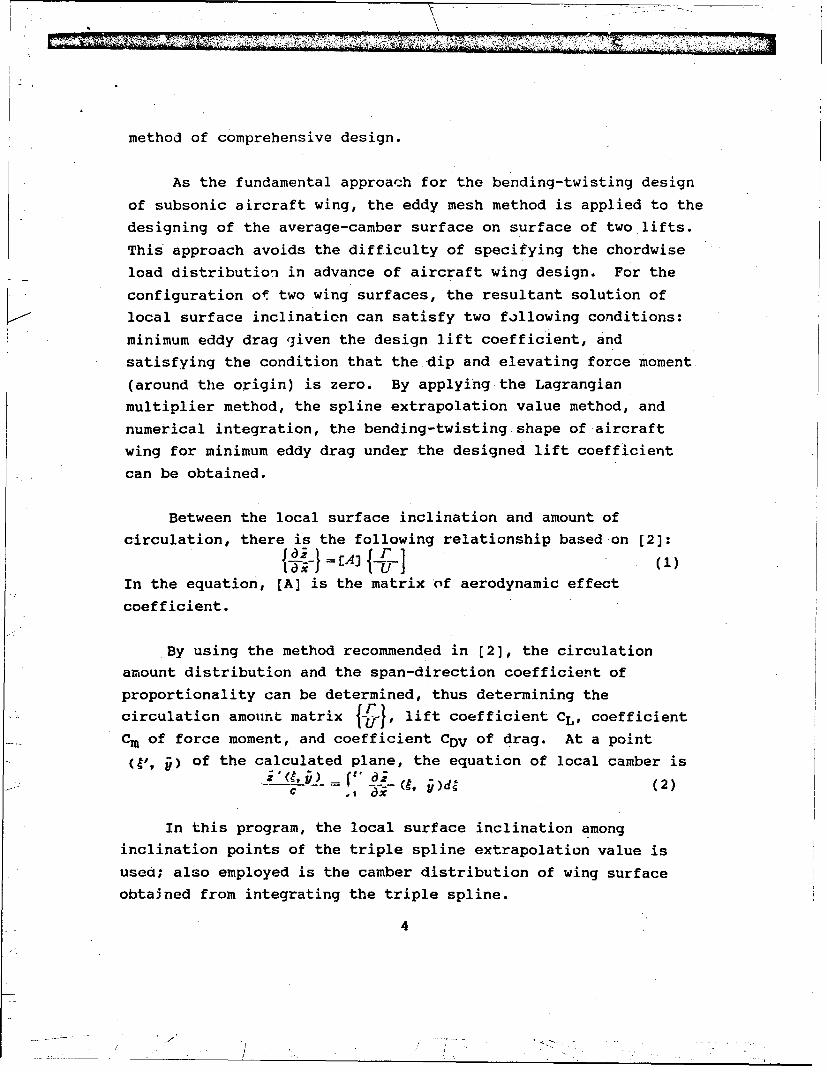
method of comprehensive design.
As the fundamental approach for the bending-twisting design
of subsonic aircraft wing, the eddy mesh method is applied to the
designing of the average-camber surface on surface of two lifts.
This' approach avoids the difficulty of specifying the chordwise
load distribution in advance of aircraft wing design. For the
configuration of two wing surfaces, the resultant solution of
local surface inclination can satisfy two following conditions:
minimum eddy drag given the design lift coefficient, and
satisfying the condition that the dip and elevating force moment
(around the origin) is zero. By applying the Lagrangian
multiplier method, the spline extrapolation value method, and
numerical integration, the bending-twisting shape of aircraft
wing for minimum eddy drag under the designed lift coefficient
can be obtained.
Between the local surface inclination and amount of
circulation, there is the following relationship based on [2]:
In the equation, [A] is the matrix of aerodynamic effect
coefficient.
By using the method recommended in [2], the circulation
amount distribution and the span-direction coefficient of
proportionality can be determined, thus determining the
circulation amount matrix , lift coefficient CL, coefficient
Cm of force moment, and coefficient CDV of drag. At a point
-(,, jj) of the calculated plane, the equation of local camber is
L-' = V, (' ((2)
In this program, the local surface inclination among
inclination points of the triple spline extrapolation value is
used; also employed is the camber distribution of wing surface
obtained from integrating the triple spline.
4

The fundamental concept and method of subsonic aerodynamic
computation are similar to those of bending-twisting design. The
fundamental computational equation can be rewritten from Eq. (1):
In the equation, azJai is the inclination of wing surface
mesh point; [A] is the aerodynamic effect cocfficient matrix,
which can be obtained from the similar method in bending-twisting
design.
From Eq. (3), after solving for the circulation amount
(PIUj of various lattice-net points on the wing surface, lift of
ti. aircraft wing, coefficient of force moment, and the induced
drag can be computed from conventional aerodynamic formulas.
In the fundamental concept of bending-twisting design and
computation of supersonic aircraft wing, a limited number of
parallelogram meshes can be divided from the mid-arc surface of
aircraft wing. Every parallelogram mesh can be considered as
iterative addition of four semifinite triangular zones. A
surface eddy with constant u is placed in each semifinite
triangular zone. See [3, 4] for details of computational formula
for induced velocity generated at a control point of the above-
mentioned surface eddy.
After placing a surface eddy with constant u on the mid-arc
surface of the aircraft wing, the algebraic equation satisfying
normal direction non-penetration at the wing surface is
[A] (P) -j3ý- a (4)
In the equation, [A] is matrix of the aerodynamic effect
coefficient; {d;ldi} is the inclination at various control
points on the wing surface;j PI is the intensity of the wing
surface eddy; and a is the incident Pngle of incoming flow.
5

By using the constraint of lift and force moment, the drag
function is derived. By applying the cornditions on deriving
extreme value with computation and manipulation, a set of.
equations as follows can be obtained.
|-
Z44j~+L=O(6)
AI, x )-j=0 (7)
See (3, 4] for derivation details. In the equations, Ai is the
area of the mesh; x is the x coordinate of the center of the
force moment; L is the constraint lift; M is the condition of
force moment; aij is the effect coefficient; and Nw is the number
of blocks into which the aircraft wing has been divided.
By solving Eqs. (5), (6) and (7), we can obtain the eddy
intensity Pi on the aircraft wing; the inclination at various
control points on the mid-arc surface can be obtained.dZW
i-9 (8)
Thus, the shape of the mid-arc surface of aircraft wing can be
determined.
The fundamental philosophy in the bending-twisting
comprehensive design of aircraft wing--canard wing (or empennage)
can be summarized into four following points:
1. Determine the site of the datum station in bending-twisting comprehensive design
In this paper, the locations of three stations at half-span
length are selected. Their spanwise locations are wing tip,
6
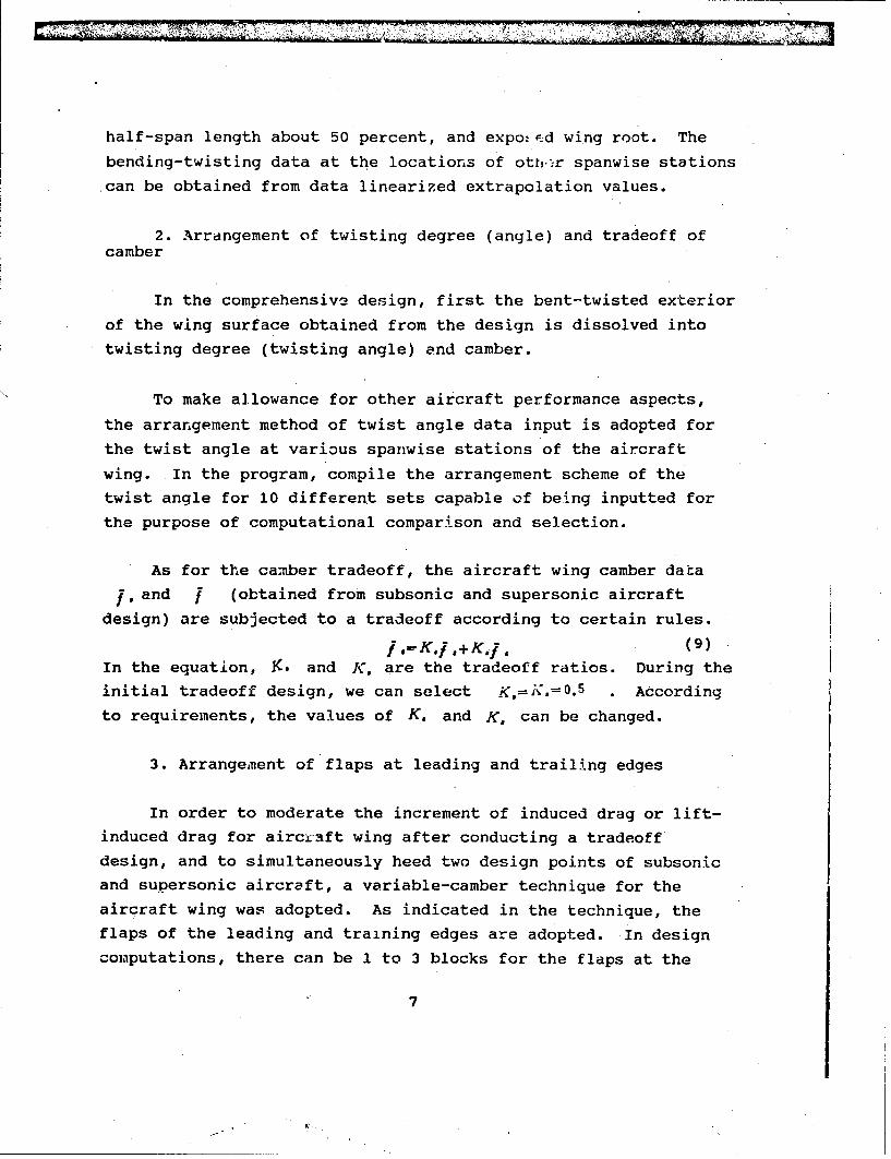
half-span length about 50 percent, and expo.&d wing root. The
bending-twisting data at the locations of ottr.Kr spanwise stations
can be obtained from data linearized extrapolation values.
2. Arrangement of twisting degree (angle) and tradeoff ofcamber
In the comprehensive design, first the bent-twisted exterior
of the wing surface obtained from the design is dissolved into
twisting degree (twisting angle) and camber.
To make allowance for other aircraft performance aspects,
the arrangement method of twist angle data input is adopted for
the twist angle at various spanwise stations of the aircraft
wing. In the program, compile the arrangement scheme of the
twist angle for 10 different sets capable of being inputted for
the purpose of computational comparison and selection.
As for the camber tradeoff, the aircraft wing camber data
j, and j (obtained from subsonic and supersonic aircraft
design) are subjected to a tradeoff according to certain rules.
S.='K.j . + K,. (9)In the equation, K. and K, are the tradeoff ratios. During the
initial tradeoff design, we can select K,=K.=0. 5 . According
to requirements, the values of K, and K, can be changed.
3. Arrangement of flaps at leading and trailing edges
In order to moderate the increment of induced drag or lift-
induced drag for airci aft wing after conducting a tradeoff
design, and to simultaneously heed two design points of subsonic
and supersonic aircraft, a variable-camber technique for the
aircraft wing was adopted. As indicated in the technique, the
flaps of the leading and training edges are adopted. In design
comaputations, there can be 1 to 3 blocks for the flaps at the
7

leadring and trailing edges; one inflexion point may exist at the
leading edge of the flap; three sets of chordwise values for the
flap can be selected; and the maximum flap camber assemblies can
be as many as 5. In this design computation, a set of flap
exterior and camber can be selected with minimum drag.
4. Wing pattern data for location of datum station
After inputting the distribution data of wing pattern
thickness, finally the wing pattern data at the spanwise locationof the datum station of the aircraft wing can be obtained.
III. Computational Results
Designing the oamber surface of canard wing--aircraft wing
proceeds with the exterior shape in first-stage aircraft design.
Compute the relative positions of changing two wing surfaces at
states of M.=0.85, C:.D=0.2, 0.=0.3, and a.=0.3. Change the
relative locations of two wing surfaces: z=70.5, -0.7, -0.84,
-1.0, and -1.2; a total 5 positions. There are 6 states for
the center of the force moment: moving forward for 10 and 5.
percent, moving backward for 5, 10 and 15 percent, as well as the
prototype for a total of 6 states. More than 30 sets of data
were computed.
Fig. 1 indicates the canard wing layout. When M_.=0.85,CL.,D=0. 2 , a,=a.=0.3, and i./(b/2)=-0.172 , Fig. 1 shows
the variation curve of the induced drag CDV in the range of
distributed flat points of the force moment.
Fig. 2 indicates the configuration of aircraft wing--canard
wing. The figure indicates the distribution of twist angles for
different vertical separate positions of aircraft wings and
canard wings for the case of M.=0.85, CL.a-0.2, ao=au=0.3,
and i,/(b/2) =-0.172
8
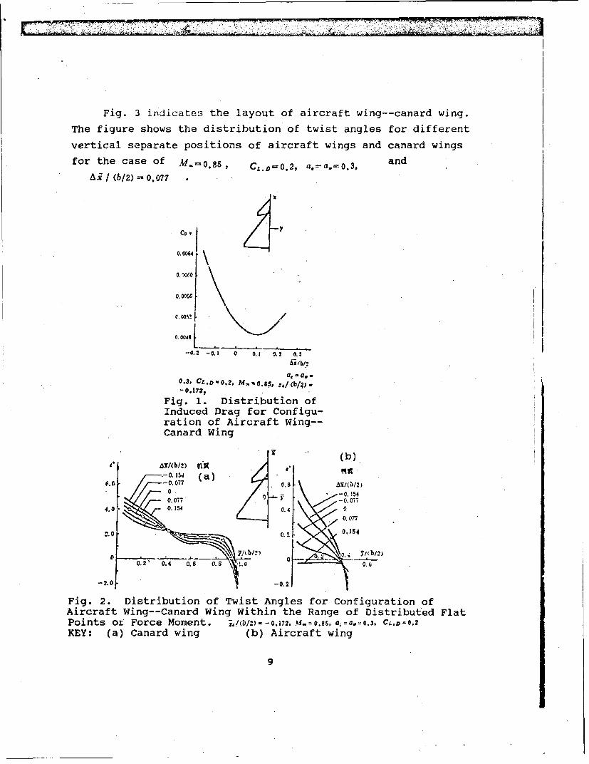
Fig. 3 indicates the layout of aircraft wing--canard wing.
The figure shows the distribution of twist angles for different
vertical separate positions of aircraft wings and canard wings
for the case of M.=0.85, C,.D=0.2, a,-a,=0.3, and
0i / (b/2) = 0.077
Cot
0.0064\
0. 0056
C. 0052
0.0048
-0.2 -0., 0 o0. 0. 0.3
Al /b/b
a, - a.,0.3. CZ.D=0. 2- M- , 0.8$, z,/ (b!/;)=
- 0.172,
Fig. 1. Distribution ofInduced Drag for Configu-ration of Aircraft Wing--Canard Wing
T (b)
-0.1o , (a)6,0 // -0.-077 ().6 A7/0/2,
0.077 -0.0#73 00 0,O ________ \ "fhij
4.0 k O 5 0.41k• 0
(k2 077,
0.2' 0.4 0.6 0 ). . 0.6
-2.0 -0.2
Fig. 2. Distribution of Twist Angles for Configuration ofAircraft Wing--Canard Wing Within the Range of Distributed FlatPoints oi Force Moment. j,/I - - 0.,172. A.t = 0.8s, a0 = a. 0.3, C4 ,D 0.2
KEY: (a) Canard wing (b) Aircraft wing
9

Bending-twisting Design of Supersonic Aircraft Wing
Altogether, 15 examples were computed by using the program
presented in this paper, which presents the computational results
for one example out of the 15.
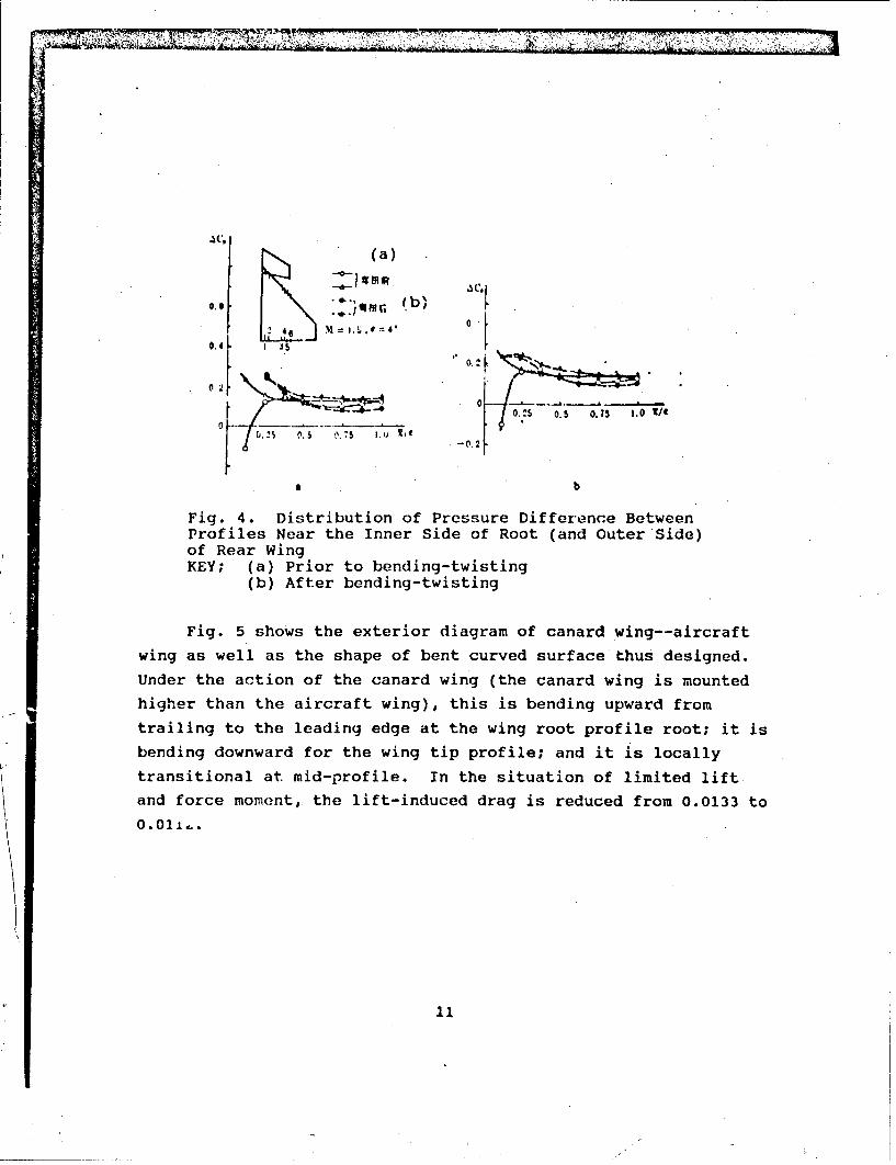
Fig. 4 presents a layout of canard -,ing--aircraft wing,
showing the distribution of pressure di.ferences prior to and
after bending-twisting of four profiles at inner and outer side
of the iircraft wing when Mv= 1.5 and a=40 . In the profile near
the wing root prior to bending-twisting, the pressure difference
at the leading edge is considerably reduced under the action of
the downstream flow field of the canard wing. As indicated by
the pressure difference after bending-twisting, the pressuredifference at the leading edge increases considerably; the
pressure difference is lowered somewhat at the trailing edge.
Thus, the pressure difference becomes moderate along the chord
direction.
• ~I "
(b),---(.03 (a) '-
I A 1.0
•rO i' -,- ,, I-'
A 0.-, CLD- . 0. - -0.S
Fig. 3. Distribution of Twist angles for Layout of AircraftWing--Canard Wing for Different Vertical Separate Positions
KEY: (a) Aircraft wing (b) Canard wing
10
AM,'
(a)
0.f0- 1 .: 1 .s 1.0 ti
-0.2
a b
Fig. 4. Distribution of Pressure Differesnce BetweenProfiles Near the Inner Side of Root (and Outer Side)of Rear WingKEY; (a) Prior to bending-twisting
(b) After bending-twisting
Fig. 5 shows the exterior diagram of canard wing--aircraft
wing as well as the shape of bent curved surface thus designed.
Under the action of the canard wing (the canard wing is mounted
higher than the aircraft wing), this is bending upward from
trailing to the leading edge at the wing root profile root; it is
bending downward for the wing tip profile; and it is locally
transitional at. mid-profile. In the situation of limited lift
and force moment, the lift-induced drag is reduced from 0.0133 to
0.01111

((b)
(d)
Fig. 5. Shape of Bending-Twistingat Exterior of Noncoplanar CanardWing--Aircraft Wing Assembly, andWing Surface: M a-.i*.-KEY; (a) Prior to bending-twisting
(b) After bending-twisting(c) Canard wing(C') Aircraft wing
Comprehensive bending-twisting design for subsonic aircraft
wing
The paper presents the design computational result of the
configuration of canard wing--aircraft wing with flap at leading
edge. The design state is as follows: at subsonic velocities,
M =0.85 and CL.D=0. 2 ; at supersonic velocities, M =1.4 and
CL.D=0. 2 .
Fig. 6 presents the distribution of bending in an aircraft
wing; the figure indicates the gradual increase in bending in the
aircraft wing from wing root to wing tip. As a result of
supersonic air velocity, an inflexion appears between y/(b/2) =
12

0.3 and 0.45.
Fig. 7 presents the distribution of twist angle at the
aircraft wing during bending-twisting design and comprehensive
design at subsonic and supersonic air velocities.
"SI (a)
(a) 4.0 (.0
O.4--. (b)
*.0- 0. (c
01 2 O. 0.4 ~ I .0,2 0.4 0.6 0.8 1.0
y/(bb/2)-4.0
Fig. 6. Camber Distribution Fig. 7. Twist-Angle Distri-at Aircraft Wing With the bution at Aircraft Wing Withoptimal Bending-Twisting Optimal Bending-Twisting DesignDesign and Comprehensive and Comprehensive DesignDesignKEY (for Figs. 6 and 7): (a) Supersonic velocity (b) Sub-sonic velocity (c) Comprehensive design
Fig. 8 presents polar curves for induced drag with three
variants of optimal design, comprehensive design and deviating
flap at subsonic air velocities. From the figure, the factor of
induced drag increases apparently after the comprehensive
tradeoff design: from 0.1410 to 0.1670. By appropriately
selecting deviation of the leading-edge flap locally, drag can be
reduced.
Fig. 9 presents polar curves for the lift-induced drag at
three variants of optimal design, comprehensive design and
deviating flap at supersonic air velocities. A similar trend is
exhibited in Figs. 8 and 9. The lift-induced drag can be reduced
by deviating the flap.
13

CCL
0.6
t (b)
0.2 - -
pfl 44~ .. t. *~4( ~ I'~0.05 0.10 0.15 C1ý
Fig. 8. Polar Curves for Fig. 9. Polar Curves for Lift-Induced Drag With Three Var- Induced Drag With Three Var-iants at Subsonic Air Veloc- iants at Supersonic Air Veloc-ities itiesKEY (for Figs. 8 and 9): (a) Optimal bending-twisting design(b) Comprehensive design (c) Calculation point of deviatingflap (d) State (e) Optimal design (f) Comprehensivedesign (g) deviating flap
As shown in the above-mentioned results, the results of the
design computations are rational. The program can be used in
first-stage design of bending-twisting aircraft wings.
IV. Conclusions
This paper systematically presents a computational method in
the optimal bending-twisting comprehensive design for subsonic
and supersonic aircraft wings. Features of this method
simultaneously make allowance for the aerodynamic performance
aspects at two design points for subsonic and supersonic
aircraft, and also consider the requirements imposed by other
aircraft performance aspects and structures, thus obtaining the
rational bending-twisting shape of the aircraft wing. As
explained by analyzing the computational examples, rational
results can be obtained with calculations that rely on computer
program of such a comprehensive design.
14
First draft of the paper was received on 8 August 1987. The
revised, final draft was received on 17 March 1988.
REFERENCES
t 13 Margason, R. J. and Lamar, J. E., NASA TND-6142.E23 Lamar, J. E., NASA TND-8090.£13 Woodward. F. A., NASA CR-69181.
[4] Zhu, Guolin et al, Preliminary Conclusion on Applying theFundamental Solution of Supersonic Air Velocity, InstituteNo. 1702, 1977.
[5] Li Yupu, Explanation on Overall Control Program on theOptimal Bending-Twisting Comprehensive Design of AircraftWing, Institute No. 611, Ministry of Aeronautics andAstronautics Industry, 1986.
15
7 . - --- .

DI= =IOTIN DIRECI TO RECIPIDE1r
OMANIZATION MICROFICHE
B085 DIVa/RS-2FI 1C509 BAII.0C509 BALLSrIC RES LAB 1C510 R&T IABS/AVEADOE?4 1C513 ARRADOOM 1C535 AVRADOUVT/SAROC14 1C539 ¶IRASANA 1Q592 FSTC 4Q619 MSIC REESIONE 1.Q008 NTIC 1Q043 AFNIC-IS 1,E051 HQ USAF/INET 1E404 AEDC/IflF 1E408 AFWL 1E410 ASDIC/IN 1E411 ASD/FflD/TrIA 1E429 SD/IND 1P005 DOE/ISA/DDI 1P050 CIAOCR/ADD/SD 21051 AFIT/I.DE 1P090 NSA/CDB 12206 FSL1
Microfiche Nbr: FrID93C000173LFI'D-ID (PS) T-0826-92
K
-1*.DATE: 1
p 73.
i