Embed Size (px)
Citation preview

Window InstallationImpact and Structural Installations
199700192021-08-02
These instructions are applicable for the following StormPlus products:Ultimate Casement1Ultimate Double Hung G2 Ultimate Direct Glaze Polygon/Round Top Ultimate Wood Double Hung Magnum
Ultimate Wood Casement1Ultimate Wood Double Hung Ultimate Wood Direct Glaze Polygon/Round Top
.1Includes Picture, Transom, Round Tops and Polygon
ABSTRACTThese instructions advise the window installer/carpenter/contractor on the recommended way to install Marvinwindows where structural installation is necessary, including those rated for use in Impact Zones 2, 3, and 4.
In addition to steps for installing your window, included within are: Rough opening (RO) preparation for recessedmasonry applications; RO prep and sealing details for standard wood frame construction; detailed fasteningmethods and more.
The procedures within these instructions are consistent with those used in testing to achieve the advertised PG(Performance Grade) rating. Contact your local Marvin dealer if your construction scenario differs from thosedetailed within.
Regional standard practices, environmental conditions and codes may vary and supersede theprocedures contained within. The responsibility for compliance is yours: the installer, inspector, andowner(s). See the Technical Installation Specifications inside for more details.
These instructions are applicable for the following Structural installations:Ultimate Wood Double Hung Magnum
NOTE: Certified IZ3 Ultimate Casement, Ultimate Double G2, Ultimate Wood Double Hung, and Ultimate Direct Glaze Polygon/Round Top units must be installed using jamb screws or structural brackets. Certified IZ3 Ultimate Double Hung Magnum units must be installed using the jamb screw method only.
NOTE: IZ4 Ultimate Casement and Direct Glaze units must be installed using jamb screws or structural brackets spaced at 4” from corners and 12” maximum on center.
Page
Table of Contents
Technical Installation Specifications 2. . . . . . . . . . . . . . . . . . . . . . . . . . . . . . . . . . . . . . . . . . . . . . . . . . . . . . . . . . .
Before You Begin 3. . . . . . . . . . . . . . . . . . . . . . . . . . . . . . . . . . . . . . . . . . . . . . . . . . . . . . . . . . . . . . . . . . . . . . . . . . . . .Installer and Builder Information, Homeowner Information, and Aftermarket Products
Step One − Rough Opening and Framing Requirements 4. . . . . . . . . . . . . . . . . . . . . . . . . . . . . . . . . . . . . . . . .Concrete Block with Plywood Buck, Concrete Block with 2� Buck or Standard Wood Framing
Step Two − Unit Preparation 6. . . . . . . . . . . . . . . . . . . . . . . . . . . . . . . . . . . . . . . . . . . . . . . . . . . . . . . . . . . . . . . . . . .Packaging, Shipping Blocks, Jamb Extension, Nailing Fin and Wood Brick Mould Casing
Step Three − Installing the Window 7. . . . . . . . . . . . . . . . . . . . . . . . . . . . . . . . . . . . . . . . . . . . . . . . . . . . . . . . . . . .Shimming, Plumbing and Squaring
Fastening Methods and Jamb/Sill Screw Chart 8. . . . . . . . . . . . . . . . . . . . . . . . . . . . . . . . . . . . . . . . . . . . . . . . .Wood Screws/Concrete Anchors and Structural Brackets
Step Four − Final Installation Procedures 10. . . . . . . . . . . . . . . . . . . . . . . . . . . . . . . . . . . . . . . . . . . . . . . . . . . . .Standard Frame Construction and Recessed Masonry Applications
Continuous Air Barrier Systems 11. . . . . . . . . . . . . . . . . . . . . . . . . . . . . . . . . . . . . . . . . . . . . . . . . . . . . . . . . . . . . .
1Window Installation
StormPlus and Structural Installations199700192021-08-02
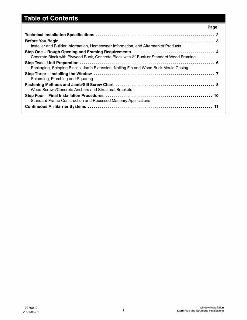
Technical Installation SpecificationsThe following details are specified for proper installation and for the unit to meet the advertised design pressure(DP) rating.
� If using less than a nominal 2� x buck in masonryopenings; the rough opening must be no more than1/2�(13) wider and 1/4�(6) taller than the outsidemeasurement of the frame. Installation methods arelimited to Jamb Screw method using 3/16� concretescrews.
� Marvin recommends the use of sloped sills on all concreteopenings (either pre−cast or poured).
� Regarding recessed masonry openings: the windowframe must not come in direct contact withmasonry/concrete/concrete block. Construct framingfrom treated lumber or plywood and fasten to the masonryopening jambs, header, and sill. This framing must bedesigned (and anchored to the opening) properly towithstand certified and advertised performance grade(PG) ratings for your particular unit.
� For installations in typical wood frame construction (withsheathing and building paper or air barrier material)where a continuous air barrier system is used, refer toASTM E2112−01 or reference the “Continuous AirBarrier Systems” section for details on preparing therough opening and sealing the installation.
� For installations in concrete block, or masonryconstruction, etc., follow local codes for sealing and watermanagement details.
� Properly flash and/or seal all windows at the exteriorperimeter.
� Sealants used for installation must be Grade NS Class 25per ASTM C920 and compatible with the building exterior,window exterior surface, and flashing/water managementmaterials.
� Flashing materials must comply with ASTM E2112−01,section 5.13 and be compatible with all materials used ininstallation including panning systems, air barriers andbuilding papers, sheathing, and the window unit.Flashing material must not contain asphalt and mustbe compatible with flexible PVC (vinyl) when used inconjunction with nailing fin.
� Optional foams used for installation must be low expansiononly. Foam and foam application must comply with ASTME2112−01, SEC 5.9.2.
� Shims are required between the window frame and framingmembers at all locking points and at every point ofattachment (excluding nailing fin and brick mould casing)as well as at all points detailed within these instructions.
� For units with flat casing install with installation brackets,structural masonry brackets, or jamb screws.
� Do not use chemically treated products for shim material.
� Fasteners penetrating chemically treated lumber must bea minimum of 0.90 oz/ft2 zinc hot dipped galvanized orstainless steel type 304 or 316.
� Clad window frames must not come into direct contact withchemically treated wood products.
� Rough Opening Width: 1/4�−1� (6−25) wider thanwindow/door frame outside measurement.
� Rough Opening Height: 1/4�−1/2� (6−13) higher thanwindow/door frame outside measurement.
� Masonry Opening Width: 1/4�−1/2� (6−13) wider thanwindow/door frame outside measurement.
� Masonry Opening Height: 1/8�−1/4� (3−6) higher thanwindow/door frame outside measurement.
Architectural Detail Manual Specifications:� Rough Opening:Width 1� (25); Height 1/2� (13).� Masonry Opening:Width 1/2� (13); Height 1/4� (6).
Be aware that the use of rigid sill pans andother barriers will decrease the roughopening height clearance. Adjust openingdimensions accordingly.
WARNING: Drilling, sawing, sanding ormachining wood products generates wooddust, a substance known to the State ofCalifornia to cause cancer. Avoid inhalingwood dust or use a dust mask or othersafeguards for personal protection.California Health and Safety Code Section25249.6.
Please consult with local authorities toproperly dispose and/or recycle allpackaging, materials, and waste.
WARNING: Older homes may containlead−based paint, which may be disturbedwhen replacing windows or performingrenovations. Consult state or localauthorities for safe handling, disposal, orabatement requirements. For moreinformation , go to www.epa.gov/lead
2Window Installation
StormPlus and Structural Installations199700192021-08-02

You Will Need to SupplySafety glasses Hearing protectionLevel SquareHammer Wood shimsInsulation Tape measurePerimeter sealant1 Sill pan flashingBacking material (foam backing rod)Low expansion foam insulation2
Appropriate fastener (see Jamb/Sill Screw Chart)Construction adhesive3
Standard Parts ShippedUnits are sent with hardware; clad units are sent withfour (4) nailing fin corner gaskets. Follow installationinstructions included with part if applicable. UDHMunits are sent with a fastening package and supple-mental installation instructions.
NOTE: Depending on the installation method, othermaterial may be needed to properly prepare and sealthe installation such as self sealing adhesive mem-brane, building paper, and seam seal tape, etc.
NOTE: Numbers listed in parentheses ( ) are metricequivalents in millimeters rounded to the nearest wholenumber.
WARNING: Always practice safety!Wear the appropriate eye, ear and handprotection, especially when workingwith power tools.
After Market ProductsAlterations to Marvin products including window films, insulating or reflective interior window treatments or additional glazingscan cause excessive heat buildup and/or condensation. They may lead to premature failures not covered under warranty byMarvin Windows and Doors.
Before purchasing or applying any product that may affect the installation or performance of Marvin windows contact themanufacturer of after market product/glazings that are not supplied by Marvin and request written product use, associatedwarranties and damage coverage. Provide this information and warranties to the end user and/or building owner for futurereference.
Hazard NotationsPlease familiarize yourself with the following hazard notations used throughout this instruction.
1Sealant must be Grade NS Class 25 per ASTM C920 and compatible with building exterior and window surface.2Optional, use low expansion foam insulation only. Foam and foam application must comply with ASTM E2112, section 5.9.2.3APA rated AFG−01 spec
Before You BeginInstaller and Builder Information� Read these instructions thoroughly BEFORE beginning to
install your Marvin window product.
� Always provide a copy of these instructions for the currentor future building owner.
� Plan sizing of rough opening and clearance from exteriorfinishing systems to allow for normal materials shrinkage orshifting (e.g. wood structure with brick veneer, allowadequate clearance at sill). Failure to do so can void theMarvin warranty coverage.
� Refer to the Technical Installation Specifications sectionfor technical specifications regarding the installation of thisproduct. These installation requirements as well as thedetails in this section must be followed to achieve theadvertised performance grade (PG) rating of this product.
� It is the responsibility of the builder, installer andsubcontractors to protect the interior and exterior ofwindows or doors from excessive contact with harshchemical washes, construction material contamination andmoisture. Damage to glazing, hardware, weatherstrip andcladding/wood can occur. Protect with painters tape and/orprotective sheathing as required. Follow all guidelinesregarding material use, preparation, personal safety anddisposal.
� Refer to the enclosed painting and staining instructions onthe last page for exterior and interior finish instructions.
� Contact your Marvin supplier if you have any questionsregarding product and materials used in manufacturing orquestions on replacement parts.
Caution Warning
Mistakes or misusecould cause damage
to the window orresult in faulty
installation and unitperformance.
Tips/HintsSeek Assistance
Mistakes or misusecould result in
personal injury and/orsevere damage tounit, equipment,and/or structure.
Help from anotherindividual is necessary
to perform this tasksafely and correctly.
Information onalternative
procedures,definitions, helpful
hints.
Impact Product
Steps related toImpact rated
products only.
3Window Installation
StormPlus and Structural Installations19970019
2021-08-02

Step 1: Rough Opening and Framing Requirements
Figure 1: Preparing openings for concrete block openings.
This section gives requirements for framing and rough opening clearances. Masonry or concrete openings must belined with a treated wood product (wood buck). You must fasten the buck to the masonry opening in a fashion thatwill withstand conditions which would be encountered under the certified and advertised PG ratings for this window.The structural integrity of this installation is only as good as the bond between the wood buck and the masonryopening. For more details, contact your Marvin representative.
1. On concrete block, masonry, or similar situations, linethe sides, head jamb, and sill with treated lumber.Attach the lumber to the masonry opening withconstruction adhesive and masonry anchors whichshould penetrate the masonry opening by at least1�−1 1/2� (25−38). See figure1a and 1b.
2. For standard wood frame construction, prepare theopening following local codes, ASTM E2112−1, or fol-low the steps in the “Continuous Air BarrierSystems” section.
3. If rigid panning is used, place a bead of silicone orconstruction adhesive over any fasteners used tohold the panning to the sill.
(a)
NOTE: Wood buck material thickness may vary. Illustrations show a 1/2� plywood and 2 x 4 buck. Installationsusing material less than 2� nominal material must use the jamb screw method of attachment and use 3/16� concreteanchors.
Treated 2 x 4 buck
1/2� treatedplywood
Masonryanchor
Constructionadhesive
NOTE: If your installation requires screwing throughthe sill for structural purposes, place a bead of sealantwhere the screws will penetrate the rigid sill panning.
4. The window frame must not come in contact withtreated lumber. If you will not be using rigid panningor shimming at the sill, apply a barrier such as a selfsealing adhesive flashing to the rough opening sill.See figure 1c.
(b) (c)
Adhesiveflashing
4Window Installation
StormPlus and Structural Installations199700192021-08-02

Step 1: Rough Opening and Framing Requirements (cont.)
Figure 2: Preparing openings for concrete block openings.
1Rough opening gap must be no more than 1/4� for products certified for use in IZ4 regions.
CAUTION! If the previous conditions arenot met, the installer must take correctiveactions to alter the opening(s) before
proceeding. It is also essential that the sheathingbehind the wall be a solid surface to ensure thatthe unit can be secured firmly to the wall. NOTE: On standard wood frame construction with
brick veneer, make sure there is at least 1/2� (13)
between bottom of window sill (or eventualplacement of the window) and the top row of brickto avoid “brick bind”.
ATTENTION: Be aware that use of rigid sill pans andother barriers will decrease the rough opening heightclearance. Adjust opening dimensions accordingly.
Rough Opening Masonry Opening
1/2�
1/2� 1/4�
1/4�
5. Rough openings1 (RO) should be 1� (25) wider thanthe outside measurement of the frame and 1/2� (13)higher. Masonry openings (MO) should be 1/2� (13)wider than the outside measurement of the frame orcasing and 1/4� (6) higher than the outside measure-ment of the frame or casing. When framing roughopening, care should be taken to ensure the sill plateis level and the opening is square, straight and plumb.See figure 2.
5Window Installation
StormPlus and Structural Installations199700192021-08-02

Step 2: Unit Preparation
1. Remove the protective packaging from the unitand dispose/recycle properly. Inspect unit forany hidden damage and report immediately toyour Marvin representative. Provide the cus-tomer service number etched on one of the topcorners of the glass. See figure 3.
2. Remove any shipping clips unless noted other-wise.
NOTE: Do not remove the vinyl shipping blocksor shipping tube assembly on Wood UltimateDouble Hungs until installation is complete(unless installing with jamb screws).
Figure 4: Extend nailing fin.
Figure 5: Apply back−caulking to BMC.
Figure 3:
3. If used on clad units, position the factory appliednailing fin/drip cap in the upright position. Seefigure 4.
4. On wood units with brick mould casing, applysealant at the casing to frame joint along thejambs and head jamb, at the sill horn to casingjoint, and at the miter corners of the casing. Seefigure 5. Tool the bead to ensure proper adhe-sion to both surfaces.
5. If you are installing a window with structuralbrackets, fasten to the window now. Follow thefastener spacing in the “Jamb/Sill ScrewChart”. Follow the instructions provided withthe brackets for details on how to fasten to unit.Ultimate Double Hung Magnum units are sentwith supplemental instructions which detail howto remove the sash and jamb fillers.
6. If you will be fastening with screws through thejambs, head jambs, and sill, remove your sashand covers or liners at this time. Refer to thesection, “Removing Interior Stops, Liners,and Fillers” and “Removing Sash” for details.
7. Install jamb extension before installing the win-dow in the rough or masonry opening. Follow in-structions provided with the jamb extension.
Customer service number
6Window Installation
StormPlus and Structural Installations199700192021-08-02

Step 3: Installing the Window
Figure 6: Plumb and square unit. (Illustration shows both structural bracket and jamb screw installation.)
The following steps provide details for structural fastening of the window to the opening. When installing windowswith nailing fin or wood brick mould casing, it may be desirable to first attach the window using these fasteningmethods in conjunction with steps 1−5. Then complete the installation by fastening with structural brackets orscrews. Always follow fastener spacing outlined in the “Jamb/Sill Screw Chart” section. On applicable constructionusing a continuous air barrier system, prepare the opening before installing the window. Refer to the “ContinuousAir Barrier Systems” section for details.
1. If rigid sill pan is not used, pan sill with alternate meth-ods or shim under window sill to ensure it does notcome in direct contact with treated lumber.
2. On some larger units such as the Ultimate DoubleHung Magnum, it may be necessary to remove thesash prior to installation. See the sash removal sec-tion for details.
3. Center the window in the opening. Level at the silland plumb the frame (interior/exterior) to desireddepth.
4. Fasten and shim the jambs at the bottom with theappropriate fastener (follow instructions in the“Fastening Methods” section). See figure 6a.
CAUTION: Proper shimming is extremelyimportant. Under−shimming or over−shimming will result in bowed jambs and
Installation Tip: On operating units, onemethod to ensure that the unit is installedsquare is to check the reveal (gap) between the
operating sash and the frame. An even reveal aroundthe entire sash generally indicates a correctlyinstalled unit and will ensure smooth operation.
or head jamb. Both conditions can contribute toimproper window operation and performance.
(b)(a)
Measurediagonallyfor square
Seek Assistance: Some large windowsand/or assemblies are very heavy. Avoidinjury by getting help to lift and position thewindow into the rough opening.
(c)
5. Fasten and shim at the top corners to square the unitin the opening. Take diagonal measurements of thewindow. When equal, the window is square in theopening. Adjust the shims and fasteners until the unitis square in the opening. See figure 6b.
6. Complete shimming and fastening at locations andspacing specified in the “Jamb/Sill Screw Chart”.See figure 6c.
7. Recheck the diagonals one more time to make surethe unit is square in the opening. Adjust fasteners asnecessary to bring to square.
8. Once the unit is installed square and plumb, operatethe sash (on operable units) to make sure it is operat-ing properly. If not, you may have to make some addi-tional adjustments to the shims and fasteners.
9. If removed, replace your stops, covers, and liners.
NOTE: Some units such as the Ultimate Double HungMagnum, IZ3 Ultimate Double Hung, and Clad UltimateDouble Hung Next Generation IZ3 feature unique fas-tening systems. For these windows refer to the “SpecialFastening Systems” section for details.
7Window Installation
StormPlus and Structural Installations199700192021-08-02
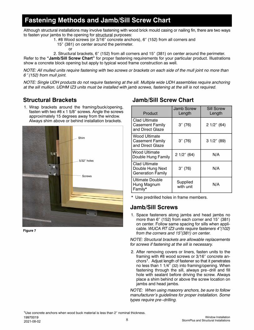
Fastening Methods and Jamb/Sill Screw ChartAlthough structural installations may involve fastening with wood brick mould casing or nailing fin, there are two waysto fasten your jambs to the opening for structural purposes:
1. #8 Wood screws (or 3/16� concrete anchors), 6� (152) from all corners and15� (381) on center around the perimeter.
or2. Structural brackets, 6� (152) from all corners and 15� (381) on center around the perimeter.
Refer to the “Jamb/Sill Screw Chart” for proper fastening requirements for your particular product. Illustrationsshow a concrete block opening but apply to typical wood frame construction as well.
NOTE: All mulled units require fastening with two screws or brackets on each side of the mull joint no more than6� (152) from mull joint.
NOTE: Single UDH products do not require fastening at the sill. Multiple wide UDH assemblies require anchoringat the sill mullion. UDHM IZ3 units must be installed with jamb screws, fastening at the sill is not required.
Jamb/Sill Screw ChartStructural Brackets1. Wrap brackets around the framing/buck/opening,
fasten with two #8 x 1 5/8� screws. Angle the screwsapproximately 15 degrees away from the window.Always shim above or behind installation brackets.
Figure 7
1/4�
5/32� holes
Shim
Screws
Jamb/Sill Screws1. Space fasteners along jambs and head jambs no
more than 6� (152) from each corner and 15� (381)on center. Follow same spacing for sills when appli-cable. WUCA RT IZ3 units require fasteners 4”(102)from the corners and 15”(381) on center.
NOTE: Structural brackets are allowable replacementsfor screws if fastening at the sill is necessary.
2. After removing covers or liners, fasten units to theframing with #8 wood screws or 3/16� concrete an-chors1. Adjust length of fastener so that it penetratesno less than 1 1/4� (32) into framing/opening. Whenfastening through the sill, always pre−drill and fillhole with sealant before driving the screw. Alwaysplace a shim behind or above the screw location onjambs and head jambs.
NOTE: When using masonry anchors, be sure to followmanufacturer’s guidelines for proper installation. Sometypes require pre−drilling.
1Use concrete anchors when wood buck material is less than 2� nominal thickness.
8Window Installation
StormPlus and Structural Installations19970019
ProductJamb Screw
LengthSill Screw
Length
Clad UltimateCasement Familyand Direct Glaze
3� (76) 2 1/2� (64)
Wood UltimateCasement Familyand Direct Glaze
3� (76) 3 1/2� (89)
Wood UltimateDouble Hung Family 2 1/2� (64) N/A
Clad UltimateDouble Hung NextGeneration Family
3� (76) N/A
Ultimate DoubleHung MagnumFamily*
Suppliedwith unit N/A
* Use predrilled holes in frame members.
2021-08-02
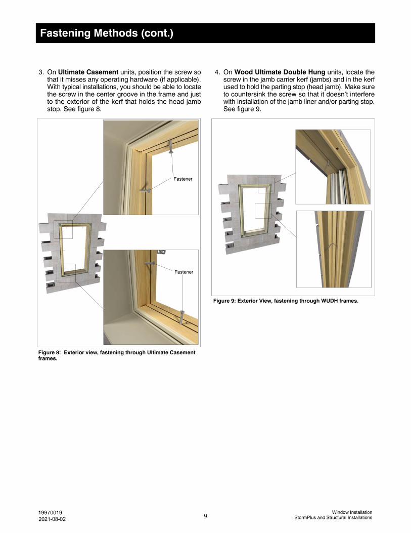
Fastening Methods (cont.)
Figure 8: Exterior view, fastening through Ultimate Casementframes.
Figure 9: Exterior View, fastening through WUDH frames.
Fastener
Fastener
3. On Ultimate Casement units, position the screw sothat it misses any operating hardware (if applicable).With typical installations, you should be able to locatethe screw in the center groove in the frame and justto the exterior of the kerf that holds the head jambstop. See figure 8.
4. On Wood Ultimate Double Hung units, locate thescrew in the jamb carrier kerf (jambs) and in the kerfused to hold the parting stop (head jamb). Make sureto countersink the screw so that it doesn’t interferewith installation of the jamb liner and/or parting stop.See figure 9.
9Window Installation
StormPlus and Structural Installations199700192021-08-02

Step 4: Final Installation Procedures
This section does not include details on sealing installations that incorporate a continuous air barrier system suchas house wrap or building paper in standard wood frame construction. For flashing details in this application referto the section, “Continuous Air Barrier Systems − Flashing the Installation”.
1. Place a bead of sealant at the wood buck to masonryjoint. See figure 10a.
2. For recessed masonry applications, Marvin recom-mends sealing at the buck to frame joint with ap-propriate width backer rod and sealant around the en-tire perimeter. Finish as applicable local code dic-tates. See figure 10b.
Figure 10: Sealing recessed masonry openings
3. In some situations such as recessed masonryopenings, you can use frame expander or otherclad accessories to finish the exterior. If this is thecase, apply a bead of sealant between the acces-sory and the masonry at the head jamb and jambsections. Leave the sill portion unsealed to allowwater to escape. See figure 10c.
4. Apply a 1�−2� (25−51) thick bead of low expansionfoam insulation on the back side of the nailing fin,brick mould casing or other trim. Do not apply toomuch as it is possible to bow the jambs. Now insulateloosely around the window with fiberglass insula-tion. See figure 11.
Backerrod
Sealant
Sealant
(c)(b)(a)
5. Interior and mullion trim: Install mullion trim afterinterior trim or casing is applied. On Wood UltimateDouble Hung units, be sure to use nails and sta-ples that are no longer than 3/4� (19). Place fasten-ers at least 1� (25) from the edge of interior jambliner.
Figure 11: Insulating the rough opening
Lowexpansionfoam
Fiberglassinsulation
10Window Installation
StormPlus and Structural Installations199700192018−07−28
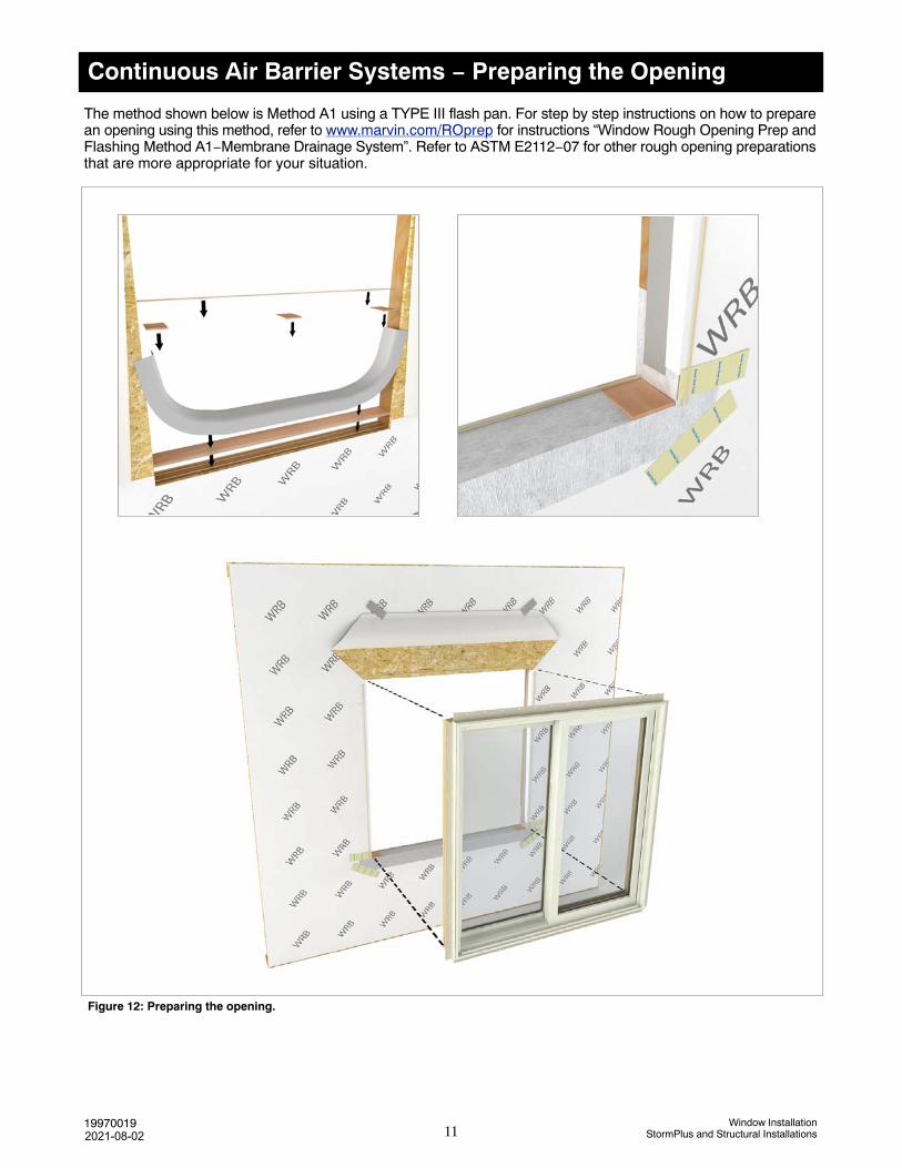
Continuous Air Barrier Systems − Preparing the Opening
Figure 12: Preparing the opening.
The method shown below is Method A1 using a TYPE III flash pan. For step by step instructions on how to preparean opening using this method, refer to www.marvin.com/ROprep for instructions “Window Rough Opening Prep andFlashing Method A1−Membrane Drainage System”. Refer to ASTM E2112−07 for other rough opening preparationsthat are more appropriate for your situation.
11Window Installation
StormPlus and Structural Installations199700192021-08-02

Continuous Air Barrier Systems − Flashing the Installation
1. Flash the installation in a weather boardfashion. For step by step instructions,refer to www.marvin.com/Roprep forinstructions titled “Window RoughOpening Prep and Flashing MethodA1−Membrane Drainage System”.
Figure 13: Sealing the installation in air barrier applications.
Drip cap
Windowcasing/cladding
Siding/exterior finish
Jambflashing
Seamseal tape
Sealant
Head jambflashing
Figure 14: Flashing windows with casing in typical wood frame construction (non recessed masonry).
Sealant
NOTE: Figure 14 shows a window with casing but the flashing detail also applies to any clad window product.
For installation in typical wood frame construction or brick veneer (non−recessed masonry openings), figure 14shows the proper flashing detail in shingle style fashion. Once the exterior finish such as siding or brick veneer isinstalled, a bead of sealant should be applied between the finish and the window/window casing along the sides andapproximately 1−2� (25−51) in from the ends at the head jamb (see insert). Use a backer rod when necessary.
Window Flashing Detail (non−recessed masonry)
12Window Installation
StormPlus and Structural Installations199700192021-08-02