Embed Size (px)
Citation preview
ED 064 899
AUTHORTITLE
INSTITUTIONPUB DATENOTE
EDRS PRICEDESCRIPTORS
IDENTIFIERS
ABSTRACT
DOCUMENT RESUME
EM 009 978
Callais, Richard T.Subscriber Response System; El Segundo Interim TestReport.Theta-Com, Los Angeles, Calif.17 May 7219p.; Paper presented at the National CableTelevision Association Annual Convention (Chicago,Illinois, May 17, 1972)
MF-$0.65 HC-$3.29Broadcast Industry; *Cable Television; InformationServices; Information Systems; *On Line Systems;Televised InstructionCATV; Subscriber Response Systems
A new cable television system, called the SubscriberResponse System (SRS), is being tested prior to a trial installationin El Segundo, California. The components include two bidirectionalcables, a computer for processing subscribers' requests, andsubscriber terminals to be located in homes or offices. The hometerminal includes a three-digit keyboard or a full numeric keyboardwith a strip printer. The first phase of testing has showed the fullSRS system transmits data with high reliability in the presence oftypical or even excessive thermal noise. Tests of the computer andsoftware showed the system can deal with heavy service traffic withan average interrogation response time from 2.4 to 13.3 seconds for50.000 subscribers. Initial consumer use of the system will be formeter-reading, shopping from the home, reservation services andemergency services. Other services to be tried may include pay TV,interactive education in the home, audience participation programsand off-track betting. mo
THETA-COM
co
U.S. DEPARTMENT OF HEALTH.EDUCATION & WELFAREOFFICE OF EDUCATION
THIS DOCUMENT HAS BEEN REPRO-DUCED EXACTLY AS RECEIVED FROMTHE PERSON OR ORGANIZATION ORIG-INATING IT. POINTS OF VIEW OR OPIN-IONS STATED DO NOT NECESSARILYREPRESENT OFFICIAL OFFICE OF EDU-CATION POSITION OR POLICY.
SUBSCRIBER RESPONSE SYSTEMEl Segundo Interim Test Report
By Richard T. Ca !leisManager, SRS Division
Presented at the NCTA ConventionChicago, Illinois - May 17, 1972
DIVISION OF THETA-CON't ,4 ).32(.) 1.
SRS EL SEGUNDO INTERIM TEST REPORT
Richard T. CallaisManager, SRS Division
Theta-Com of CaliforniaLos Angeles, California
INTRODUCTION AND SUMMARY
This paptr is presented as a progress report on the interim test-ing of the Sabscriber Response System (SRS), in preparation forthe field installation at El Segundo.
This first phase of the overall test plan includes tests made atTheta-Com using actual two-way cable cascades, a two-way AMLmicrowave link, and the prototype SRS terminals which will beused at El Segundo.
Data taken in these tests indicate the performance of the full SRSsystem in operation with a 16-amplifier cascade are substantiallyerror free in the presence of typical or even excessive thermalnoise. Excellent performance was also obtained in the presenceof simulated impulse noise and interfering CW carriers.
The factors which are important in the design of an interactivesystem including the oft-neglected computer and its softwarecomplement are discussed. The results of tests simulatingheavy service traffic show the SRS system can respond in sec-onds to such traffic, including the recording of billing informa-tion on magnetic tape.
Finally, the services which will be tested at El Segundo arecategorized and discussed.
THE SRS SYSTEM
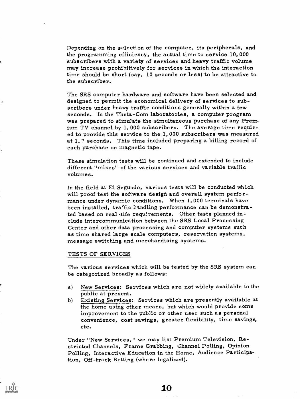
The SRS system is a two-way interactive system, the basic opera-tion of which is illustrated in Figure 1.
The two-way interactive communication takes place between acomputer complex termed the Local Processing Center (LPC),shown in Figure 2, and subscriber terminals located in the homeor business location. The subscriber terminals consist of twobasic units - a Modem, shown in Figure 3, and a SubscriberConsole.
The Modem unit contains no operating controls and can be locatedbehind the television set or in some other relatively nearby, unob-trusive location.
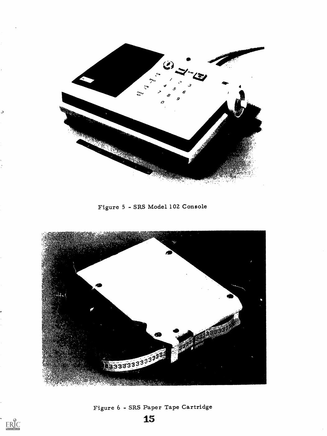
The Subscriber Console is connected to the Modem by a smalldiameter cable (nominally a maximum of 50 feet in length) and isintended to be located within view of the television set. Twomodels of the Subscriber Console are currently available. TheSRS Model 101, shown in Figure 4, contains a simple 3-digit key-board. The SRS Model 102, shown in Figure 5, has a full 0 to 9numeric keyboard and a strip printer. A paper tape cartridgeused in conjunction with the strip printer is shown in Figure 6.
The units shown are operating samples from the prototype pro-duction run of 30 terminals.
More detail describing the basic SRS system is available in Ref-erence [1].
EL SEGUNDO TEST PLAN
Starting in late spring of this year, the Theta-Com SRS systemwill be tested on a Theta-Cable two-way CATV installation nownearing completion infhe City of El Segundo, California.
Initial testing will be performed with 30 of the prototype SRS ter-minals and will be continued and extended with the production andinstallation of 1,000 pre-production terminals starting at the endof 1972.
The initial tests using 30 terminals will combine technical testingand demonstrations and development of the services offered.These studies will continue as the 1,000 units are installed andwill phase into the sale of actual services.
EL SEGUNDO CABLE SYSTEM
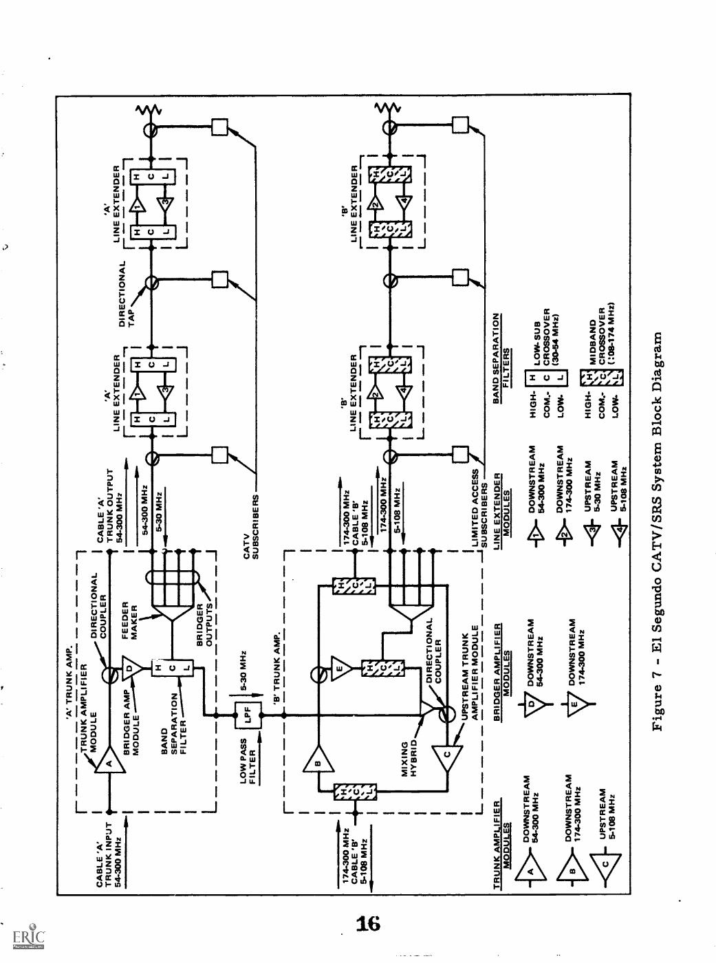
The CATV system being installed in El Segundo by Theta-Cable isa two-cable system, shown in Figure 71. The system consists ofan "A" cable system and a "B" cable system. The "A" cable trunkline is intended for downstream transmission only in the band from54 to 300 MHz. The "B" trunk line operates bi-directionally:downstream from 174 to 300 MHz, and upstream from 5 to 108MHz. The "A" cable distribution system, however, operates bi-directionally with the upstream bandwidth between 5 and 30 MHz.Upstream signals from "A" distribution line are routed throughappropriate low pass filters to the "B" trunk where they travel
'Diagram furnished by Mr. Thomas H. Ritter, TelePrompTerCorporation.
upstream to the head end and are routed to the SRS Local Proces-sing Center. The "A" trunk, and distribution system, is intendedprimarily for home subscribers while the "B" trunk is intendedfor municipal, business, and industrial usage, where the greaterupstream bandwidth (5-108 MHz) can be utilized for additionaldata communication and/or upstream video channels.
The "A" cable system will contain 32 trunk amplifiers and 124line extenders. The "B" cable system will contain 32 trunk am-plifiers and only 4 line extenders, in view of the smaller distri-bution demand anticipated from the specialized users.
The longest cascade in the system consists of 7 trunk amplifiersand 2 line extenders. Total plant mileage is approximately 30miles. For the trunk, 3/4" foam dielectric cable will be usedand 1/2" cable for the distribution system.
TESTS IN PROGRESS
While the El Segundo cable system construction is nearing com-pletion, extensive testing of the SRS system using actual cablecascades is in progress at the Theta-Com plant. This testingand other developmental efforts will continue at Theta-Comusing a second LPC following installation of the present LPCin El Segundo.
DUAL CABLE TESTS
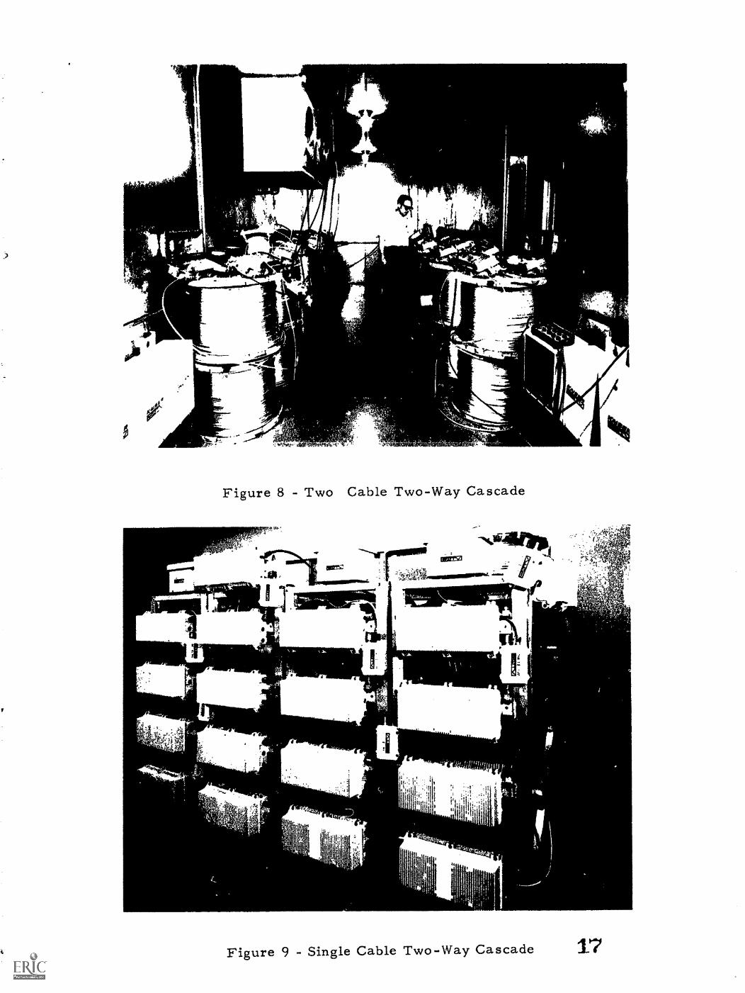
A two-way two-cable system, representative of the El Segundoinstallation, has been assembled at the Theta-Com facility inLos Angeles. The cable cascade is shown in Figure 8 installedin a large temperature chamber where it has been extensivelytested. Reels of aluminum sheath cable similar (except forsmaller diameter) to the actual trunk cable are used to providea 20 dB spacing measured at 300 MHz between amplifiers. Six-teen downstream amplifiers are used in the "A" trunk systemand sixteen two-way amplifiers are employed in the "B" cabletrunk.
For the El Segundo system, Jerrold SP-1/2/5-2W trunk ampli-fiers and SLE-300-2W line extenders are used.
While testing of this system is still underway, some initial re-sults can be reported at this time.
Tests were made using an SRS 101 terminal and the full LPCcomputer complex feeding the aforementioned cascaded cablesystem. During the tests, 12 channels of video were being car-
ried over the cable, plus the FM band. Computer controlledoperation of all of the basic services, including channel selec-tion, channel polling, meter reading, opinion polling, premiumand restricted TV control, accessory power contrul and emer-gency alarms were repeatedly demonstrated satisfactorily.
Tests are also being conducted to determine two-way systemerror performance. For these tests, a special LPC computerprogram was written to control the transmission of downstreamcommands such that four different commands were sent to anSRS terminal in sequence and the cycle was repeated indefinitely.In response to each of these commands, the terminal transmit-ted upstream different responses in accordance with the down-stream command. These tests were performed using the 16-amplifier dual cable cascade.
The computer compared the responses to each command with thenormal response expected and periodically read out to a teletypethe total number of errors and the type of error. Over a periodof 11 hours during which approximately 40 million complete two-way transmissions, comprising a total of 2.5 billion bits, weremade with no errors. This error value corresponds to a bit
-10error rate of 4x10 if we assume the next transmission (afterthe end of the actual test) were to contain an error. This wouldcorrespond to a signal to noise ratio of roughly 17 dB [21. Ac-tually, the S/N ratio was in excess of 40 dB, and the correspon-ding error rate due to thermal noise in the test cascade with thisS/N would be vanishingly small.
For actual field installations, the thermal noise from each sub-scriber house drop will add since the signal paths all convergeto the trunk and eventually the Head End and LPC. For an ex-tremely large CATV sysfem, perhaps close to a worse case,let us assume we have approximately 300 miles of strand, and1,000 reverse amplifiers. The resulting S/N calculated forreverse amplifiers with a noise figure of 10 dB, 23 dB of gain,operating at a +32 dBmV output level is 28 dB for a 4-MHz band-width [3]. This will again result in a vanishingly small errorrate for data signals but a very poor upstream video signal.
In El Segundo, there will be approximately 160 reverse ampli-fiers which will cause no thermal noise problems for the SRSbut may degrade video picture quality. In this event, provisionhas been made to operate in a type of hub fashion with two trunklines in place of one.
Some attempt was made to determine the performance of the
system with simulated impulse noise and with interfering carrisrsignals.
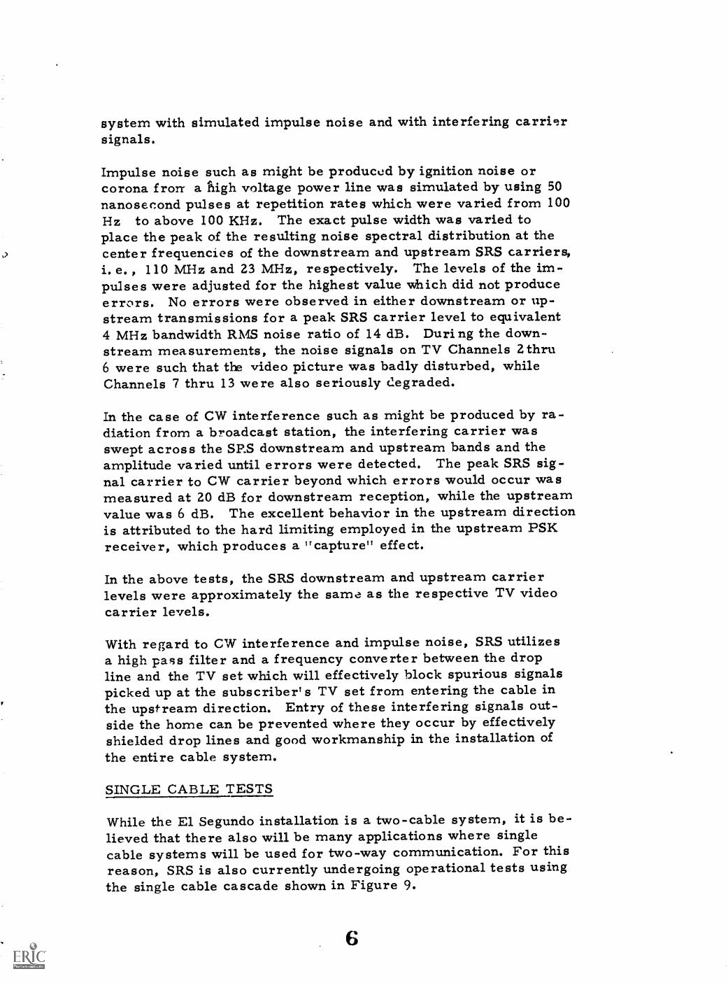
Impulse noise such as might be producod by ignition noise orcorona fron- a Puigh voltage power line was simulated by using 50nanosecond pulses at repetition rates which were varied from 100Hz to above 100 KHz. The exact pulse width was varied toplace the peak of the resulting noise spectral distribution at thecenter frequencies of the downstream and upstream SRS carriers,1. e. , 110 MHz and 23 MHz, respectively. The levels of the im-pulses were adjusted for the highest value which did not produceerrors. No errors were observed in either downstream or up-stream transmissions for a peak SRS carrier level to equivalent4 MHz bandwidth RMS noise ratio of 14 dB. During the down-stream measurements, the noise signals on TV Channels 2thru6 were such that tlE video picture was badly disturbed, whileChannels 7 thru 13 were also seriously degraded.
In the case of CW interference such as might be produced by ra-diation from a broadcast station, the interfering carrier wasswept across the SRS downstream and upstream bands and theamplitude varied until errors were detected. The peak SRS sig-nal carrier to CW carrier beyond which errors would occur wasmeasured at 20 dB for downstream reception, while the upstreamvalue was 6 dB. The excellent behavior in the upstream directionis attributed to the hard limiting employed in the upstream PSKreceiver, which produces a "capture" effect.
In the above tests, the SRS downstream and upstream carrierlevels were approximately the same as the respective TV videocarrier levels.
With regard to CW interference and impulse noise, SRS utilizesa high pass filter and a frequency converter between the dropline and the TV set which will effectively block spurious signalspicked up at the subscriber's TV set from entering the cable inthe upstream direction. Entry of these interfering signals out-side the home can be prevented where they occur by effectivelyshielded drop line s and good workmanship in the installation ofthe entire cable system.
SINGLE CABLE TESTS
While the El Segundo installation is a two-cable system, it is be-lieved that there also will be many applications where singlecable systems will be used for two-way communication. For thisreason, SRS is also currently undergoing operational tests usingthe single cable cascade shown in Figure 9.
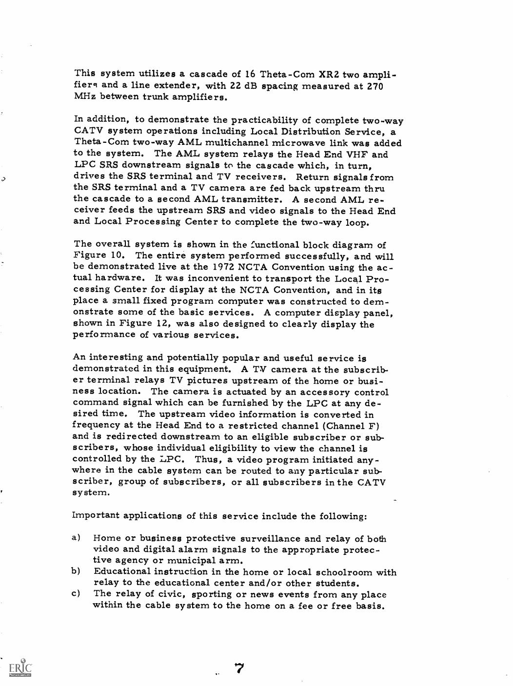
This system utilizes a cascade of 16 Theta-Com XR2 two ampli-fierci and a line extender, with 22 dB spacing measured at 270MHz between trunk amplifiers.
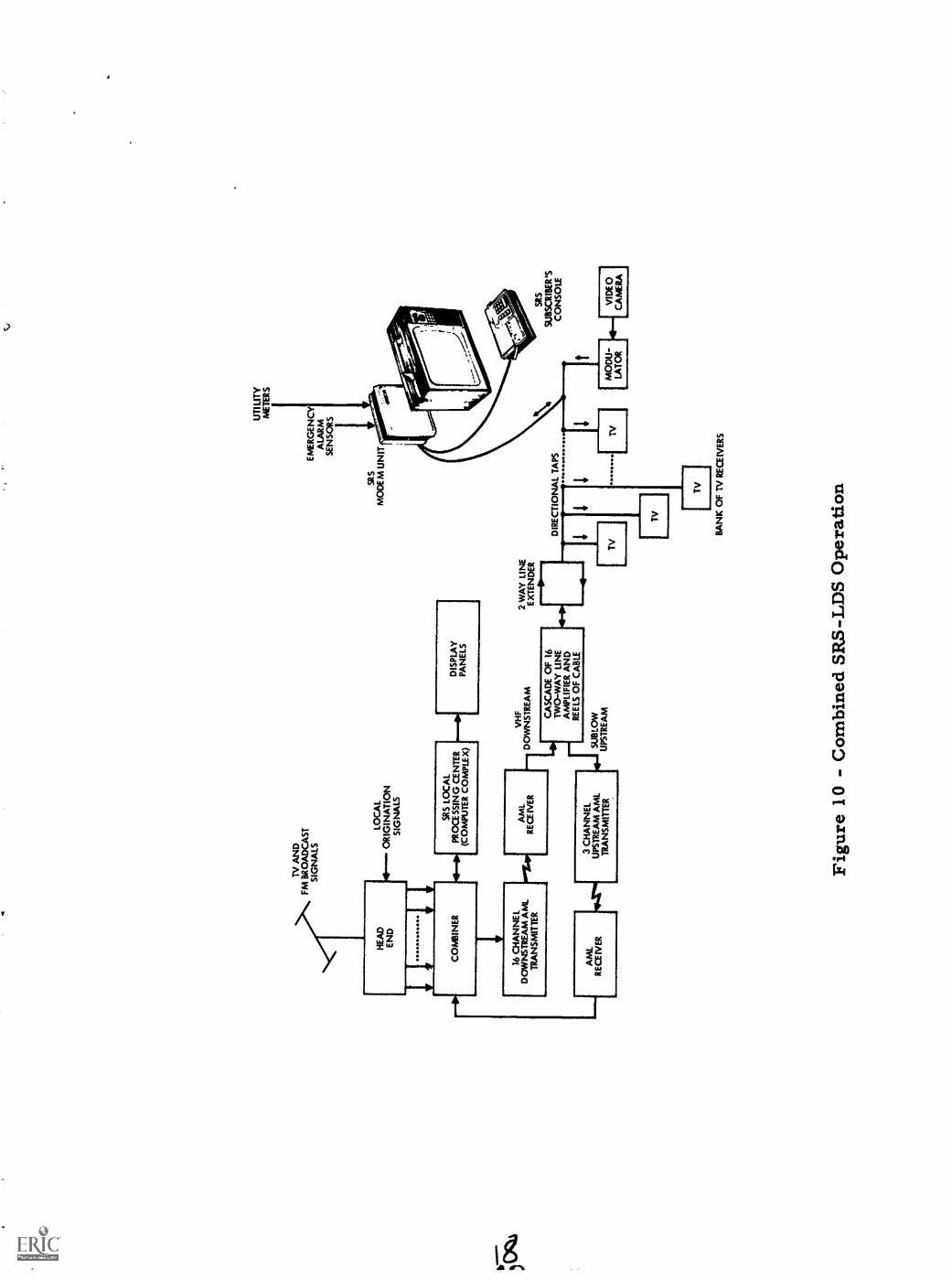
In addition, to demonstrate the practicability of complete two-wayCATV system operations including Local Distribution Service, aTheta-Corn two-way AML multichannel microwave link was addedto the system. The AML system relays the Head End VHF andLPC SRS downstream signals to the cascade which, in turn,drives the SRS terminal and TV receivers. Return signals fromthe SRS terminal and a TV camera are fed back upstream thruthe cascade to a second AML transmitter. A second AML re-ceiver feeds the upstream SRS and video signals to the Head Endand Local Processing Center to complete the two-way loop.
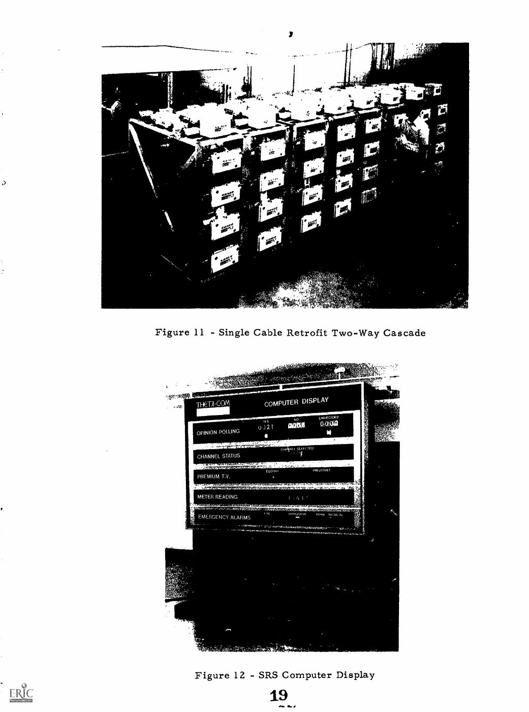
The overall system is shown in the functional block diagram ofFigure 10. The entire system performed successfully, and willbe demonstrated live at the 1972 NCTA Convention using the ac-tual hardware. It was inconvenient to transport the Local Pro-cessing Center for display at the NCTA Convention, and in itsplace a small fixed program computer was constructed to dem-onstrate some of the basic services. A computer display panel,shown in Figure 12, was also designed to clearly display theperformance of various services.
An interesting and potentially popular and useful service isdemonstrated in this equipment. A TV camera at the subscrib-er terminal relays TV pictures upstream of the home or busi-ness location. The camera is actuated by an accessory controlcommand signal which can be furnished by the LPC at any de-sired time. The upstream video information is converted infrequency at the Head End to a restricted channel (Channel F)and is redirected downstream to an eligible subscriber or sub-scribers, whose individual eligibility to view the channel iscontrolled by the LPC. Thus, a video program initiated any-where in the cable system can be routed to any particular sub-scriber, group of subscribers, or all subscribers in the CATVsystem.
Important applications of this service include the following:
a) Home or business protective surveillance and relay of bothvideo and digital alarm signals to the appropriate protec-tive agency or municipal arm.
b) Educational instruction in the home or local schoolroom withrelay to the educational center and/or other students.
c) The relay of civic, sporting or news events from any placewithin the cable system to the home on a fee or free basis.
In addition to single cable two-way syst,Ims which can be in-stalled with integral two-way distribution equipment in newconstruction, there is also the need to retrofit existing one-waysystems with two-way capability at minimal cost.
In these cases, the existing downstream amplifiers will be re-tP.ined and new upstream amplifiers and filters will be retro-fitted into the system. The cascade shown in Figure 11 is ap-plicable to the situation. It consists of 32 existing Theta-CornXR downstream amplifiers, retrofitted with 16 The.a-ComXR2SL amplifiers and 32 XR2CF series filters for upstreamtransmission. The downstream amplifiers are mounted onthe front of the racks while the upstream retrofitted compo-nents are mounted on the top.
COMPUTER SOFTWARE CONSIDERATIONS AND TESTS
It needs to be emphasized that a successful two-way interactivecommunication involves not only subscriber terminals, a two-way cable system, and equipment to modulate and demodulatedata signals on r.f. carriers - but also a reliable and efficientcomputer system which is generally associated with the head end.The computer, in turn, requires software control to perform itsfunction of interrogation of the subscribers and more important,servicing the subscriber's needs.
It would be misleading to consider only the time required to in-terrogate subscribers if we wish to determine the actual time agiven two-way system requires to handle the subscriber's re-quests. The degree of traffic volume and diversity of serviceswhich can be accommodated by a given computer software sys-tem are also significant factors in evaluating the overall cap-ability of a two-way system.
In these early days of two-way CATV systems, these considera-tions may be overlooked, or de-emphasized as less importantthan introducing some form of hardware into public test and useas soon as possible. While the view is to some extent under-standable, it may be shortsighted from the cable system opera-tor's vantage in that it may lead to early obsolescence of systemswhich are limited in the ability to handle large numbers of sub-scriLers and many services or which cannot service heavy traf-fic demand economically, efficiently, or at all.
Viewed in proper perspective, rapid interrogate and responsetimes, however, are certainly important qualities for any effec-tive system. Two factors determine this portion of the totalservicing time required: first, the speed of data transmission
8
and second, the effect of propagation delay of the cable system.
The &RS system transmits digital data downstream and upstreamat a rate of 1 megabit per second. The effects of propagationdelay are effectively reduced to a negligible amount in the SRSsystem by the Use of proprietary system design features. Thecombination of the relatLvely hiqh bit rate and the reduction inthe effects of propagation delay permit a total basic interroga-tion and response time less than approximately 2.4 seconds for50,000 subscribers.
In systems which do not effectively eliminate the effect of pro-pagation delay, interrogation-response sequences must allow atime delay equal to twice the propagation time between the com-puter and the farthest subscriber in order to avoid the possibilityof interfering responses from 2 subscribers. For a maximumcable distance of 10 miles, the comparable time required to poll50,000 subscribers would increase to approximately 7.9 seconds,an increase of approximately 325% in elapsed time. Dependingon the service being provided, there may be several interactivecontacts required between computer and subscriber to completethe required sequence of events which will increase the servicetime proportionately.
The use of two-way microwave relays between the head end andthe cable system will also directly add further propagation delaydepending on the lerth of the microwave path. For an additional10 miles due to microwave link path length, the time to service50,000 subscribers would increase from 7.9 seconds to approy-imately 13.3 seconds, while the SRS service time would remainsubstantially constant at 2.4 seconds.
Other significant factors in determining actual service time arethe speed of the operation of the computer in performing instruc-tions, the core memory cycle time, the access times to diskmemory and magnetic -cape recorder, when required, and theoverall efficiency of the software program controlling the dataprocessing task. The time required for the performance of theseoperations is generally additive to the basic interrogate-responsetimes discussed previously, since the subscriber responses mustbe received by the computer before the processing of the respon-ses and service requests can occur. Related to these factors arethe economic factors involving tradeoff considerations with re-spect to the cost of the computer and its peripherals. Increasingthe amount of core or semiconductor memory used, for example,may speed up service time but the cost may increase prohibi-tively.
Depending on the selection of the computer, its peripherals, andthe programming efficiency, the actual time to service 10,000subscribers with a variety of services and heavy traffic volumemay increase prohibitively for services in which the interactiontime should be short (say, 10 seconds or less) to be attractive tothe subscriber.
The SRS computer hardware and software have been selected anddesigned to permit the economical delivery of services to sub-scribers under heavy traffic conditions generally within a fewseconds. In the Theta-Com laboratories, a computer programwas prepared to simulate the simultaneous purchase of any Prem-ium TV channel by 1,000 subscribers. The average time requir-ed to provide this service to the 1,000 subscribers was measuredat 1.7 seconds. This time included preparing a billing record ofeach purchase on magnetic tape.
These simulation tests will be continued and extended to includedifferent "mixes" of the various services and variable trafficvolumes.
In the field at El Segundo, various tests will be conducted whichwill proof test the software design and overall system perfor-mance under dynamic conditions. When 1,000 terminals havebeen installed, trefic I7andling performance can be demonstra-ted based on real ..tife requ!rements. Other tests planned in-clude intercommunication between the SRS Local ProcessingCenter and other data processing and computer systems suchas time shared large scale computers, reservation systems,message switching and merchandising systems.
TESTS OF SERVICES
The various services which will be tested by the SRS system canbe categorized broadly as follows:
a) New Services: Services which are not widely available to thepublic at present.
b) Existing Services: Services which are presently available atthe home using other means, but which would provide someimprovement to the public or other user such as personalconvenience, cost savings, greater flexibility, time savings,etc.
Under "New Services," we may list Premium Television, Re-stricted Channels, Frame Grabbing, Channel Polling, OpinionPolling, Interactive Education in the Home, Audience Participa-tion, Off-track Betting (where legalized).
10
Under "Existing Services," we may list Meter Reading, Shop-at-Home, Reservation Services, Emergency Services, and variousderivatives of these services.
The "New Services," by definition, will provide new experiencesfor the public which may well be attractive enough by themselvesto gain widespread acceptance of interactive CATV.
Conversely, the improvement& which may be offered by some ofthe "Existing Services," such as Shop-at-Home may furnish theinitial trigger for widespread utilization of interactive services.
Once significant acceptance is obtained for some of the services,the cost of home terminals can be substantially justified on thebasis of the additional revenues provided. At this point, someof the services listed as "Existing Services" may well be divert-ed from their present media to CATV. This could occur on thebasis of the added improvements referred to above, the forma-tion of new public habit patterns, and increasing availability ofCATV and interactive systems in competition with other esta-blished media.
In El Segundo, it is planned to test the aforementioned servicesand others, where practical. The initial tests utilizing some 30Subscribar Terminals will be developmental tests to demonstrateand develop the services for cable system operators and otherenterpreneurs in a realistic environment, i.e., on an operatingtwo-way cable system in subscribers' homes. The tests willtake place over, perhaps, six months and phase into testing1,000 terminals as they are installed in subscribers' homes.
The tests utilizing 1, 000 terminals will deliver actual servicesto the subscribers on a fee basis, where applicable. The reac-tion of the subscribers to these services, the profitability of theservices, and the need for change or modification in the imple-mentation of the services will be studied in this phase.
CONCLUSION
The El Segundo tests are planned to comprehensively demon-strate the technical feasibility of two-way interactive CATVcommunications, and to attempt to determine public acceptanceof the services offered.
With regard to technical feasibility, the results to date have cor-roborated and considerably extended previous test evidence ob-tained in the field at Los Gatos, California in 1971, indicatingbasic soundness of the SRS system design.
11
With regard to public acceptance, the El Segundo tests will con-stitute a serious and significant attempt to interact with the lifestyle of the public to determine the roles best suited to this newtechnological medium and to demonstrate and measure its publicvalue and marketability.
REFERENCES
[1] R. T. Callais and E. W. Durfee, "The Subscriber ResponseSystem," paper presented at the 1971 NCTA Convention.
[2] E. D. Sunde, "Ideal Binary Pulse Transmission by AM andFM," The Bell System Technical Journal, November, 1959,
pg. 1408.
[3] System Applications brochure for XR2 Equipment, publishedby Kaiser CATV Division (now Theta-Corn CATV Division),Phoenix, Arizona, pg. 43.
TV SIGNALS
MODEM UNIT
LOCALORIGINATIONSTUDIO
DIRECTIONAL COUPLER
LINEEXTENDER
Figure 1 - Overall CATV Two-Way System
f t dr..,ft *-^
. .
SUSSCRIBER'SCONSOLE
44.
-. ,
j oct
.;;,...
Figure 2 - SRS Lfg.1 Processing Center
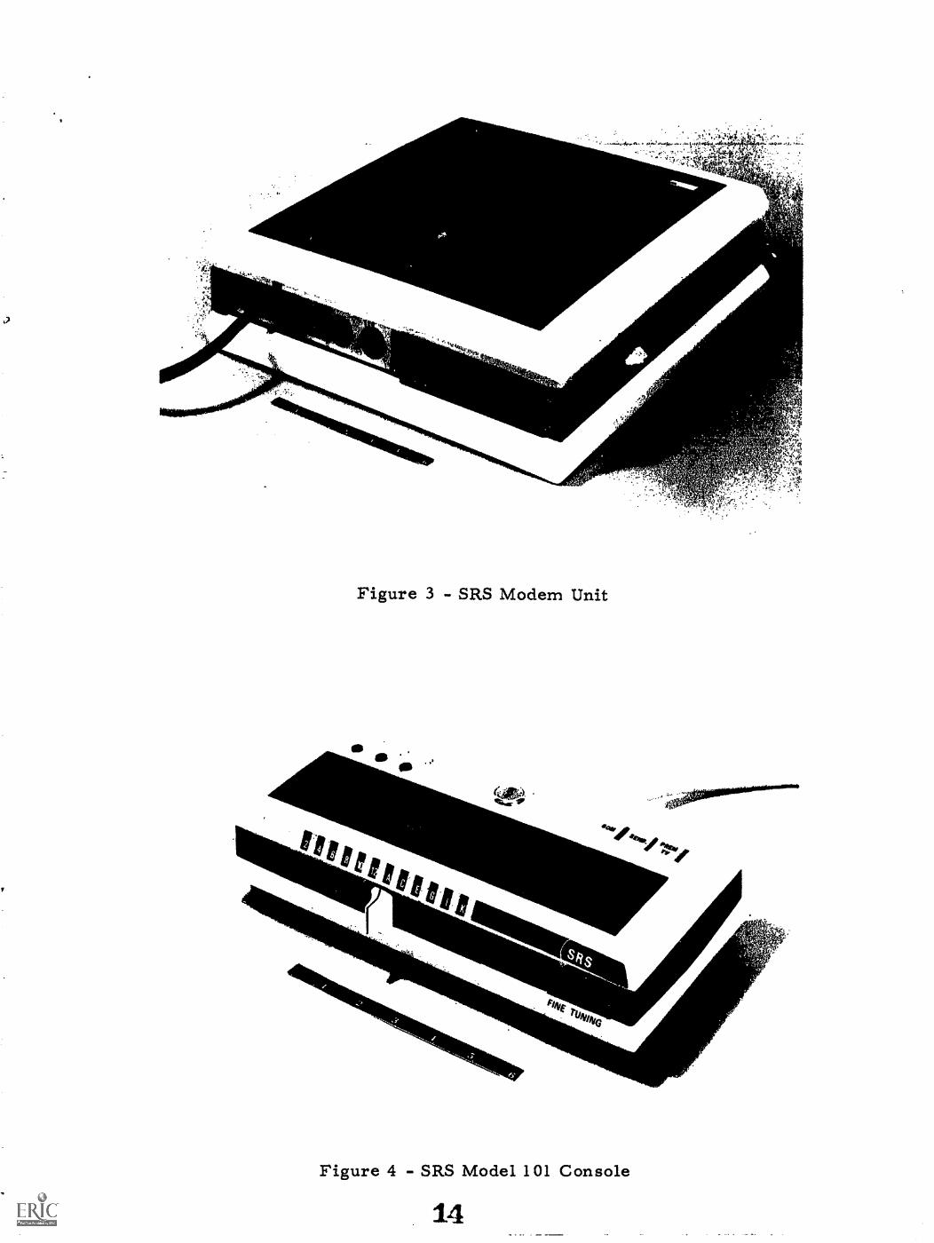
Figure 3 - SRS Modem Unit
-.^#..,- .-*"t:477.1
c*,
P411E rtiatvIW
Figure 4 - SRS Model 101 Console
t"
l YIPtiti) e'sV. s,
--t:ANif e. Ct'''' .."4.='"i'i
v11\,
CA
BLE
'A'
TR
UN
K IN
PU
T54
-300
MH
z
I- I 1,...
......
.I I I I I L I I I I
174-
300
MH
z
4....
,H
I I I I I I I I
'A T
RU
NK
AM
P.
TR
UN
K A
MP
LIF
IER
MO
DU
LED
IRE
CT
ION
AL
CO
UP
LER
BR
IDG
ER
AM
PM
OD
ULE
FE
ED
ER
MA
KE
R
-I IC
AB
LE 'A
'4
TR
UN
K O
UT
PU
T`
54-3
00 M
Hz
1
1111
0.
Mo.
LIN
E E
XT
EN
DE
R
rI/MIM
I11
110
MIII
I1.
0 I1
'
BA
ND
SE
PA
RA
TIO
NC
FIL
TE
R -
-'*--
4.."
L
FIL
TE
RLO
W P
AS
SI L
PFt
MI O
M..
OR
ON
O.
0111
111.
1O
NIII
ON
D
5-30
MH
z
1
5-30
MH
z
BR
IDG
ER
OU
TP
UT
S
'W T
RU
NK
AM
P.
1/11
1.11
1011
1011
*41
111.
0011
1101
0010
110
a/M
OM
CA
BLE
'El'
5-10
8 N
I Hz
c
TR
UN
K A
MP
LIF
IER
MO
DU
LES
t I CA
TV
SU
BS
CR
IBE
RS
i 1 I
INIW
IMI
1111
11,
OM
NI.
NO
DIR
EC
TIO
NA
LT
AP
Y
LIN
E E
XT
EN
DE
R
H ci
4
..1...
.L
1
t__
_ _
.2_,
,HI
NN
.i17
4-30
0 M
Hz
CC
AB
LE 'E
r.
15-
108
MH
z\ L
4
I...
a...
174-
300
MH
z
5-10
8 M
Hz
'B'
LIN
E E
XT
EN
DE
R11
11*
..1_.
.1
MIX
ING
HY
BR
ID
DO
WN
ST
RE
AM
54-3
00 M
Hz
DO
WN
ST
RE
AM
174-
300
MH
z
......
UP
ST
RE
AM
5-10
8 M
Hz
DIR
EC
TIO
NA
LC
OU
PLE
R
UP
ST
RE
AM
TR
UN
KA
MP
LIF
IER
MO
DU
LE
BR
IDG
ER
AM
PLI
FIE
RM
OD
ULE
S
DO
WN
ST
RE
AM
54-3
00 M
Hz
DO
WN
ST
RE
AM
174-
300
MH
z
1LI
MIT
ED
AC
CE
SS
I SUB
SC
RIB
ER
SLI
NE
EX
TE
ND
ER
MO
DU
LES
H N1
I Er
LIN
E E
XT
EN
DE
Rill
MO
4111
1111
fl 1
1111
110
0111
1
1
L`
1
DO
WN
ST
RE
AM
54-3
00 M
Hz
DO
WN
ST
RE
AM
174-
300
MH
z
UP
ST
RE
AM
5-30
MH
z
UP
ST
RE
AM
5-10
8 M
Hz
BA
ND
SE
PA
RA
TIO
NF
ILT
ER
S
HIG
H-
CO
M.-
LOW
-
H C L
HIG
H-
'
CO
M.-
LOW
-
LOW
- S
UB
CR
OS
SO
VE
R(3
0-54
MH
z)
M I
DB
AN
DC
RO
SS
OV
ER
( 08
-174
MH
z)
pp
Figu
re 7
- E
l Seg
undo
CA
TV
/SR
S Sy
stem
Blo
ck D
iagr
am
;.`
ii
;11:. j
,
'eno.; grar %none), t N.
Figure 8 - Two Cable Two-Way Cascade
ni,a, :Fs.
IT
4 4
4.
4111116 b A -
i",is; '
Figure 9 - Single Cable Two-Way Cascade 17
TV
AN
DF
M B
RO
AD
CA
ST
SIG
NA
LS
HE
AD
EN
D
LOC
AL
OR
IGIN
AT
ION
SIG
NA
LS
CO
MB
INE
RS
RS
LO
CA
LP
RO
CE
SS
ING
CE
NT
ER
(CO
MP
UT
ER
CO
MP
LEX
)
16 C
HA
NN
EL
DO
WN
ST
RE
AM
AM
.T
RA
NS
MIT
TE
R
AM
LR
EC
EIV
ER
AM
LR
Ea1
VE
R
3 C
HA
NN
EL
UP
ST
RE
AM
AM
LT
RA
NS
MIT
TE
R
--41
0D
ISP
LAY
PA
NE
LS
VH
FIO
WN
ST
RE
AM
CA
SC
AD
E O
F 1
6T
WO
-WA
Y L
INE
AM
PLI
FIE
R A
ND
RE
ELS
OF
CA
BLE
efS
UB
LOW
UP
ST
RE
AM
2 W
AY
LIN
EE
XT
EN
DE
R
UT
I LIT
YM
ET
ER
S
E M
ER
GE
NC
YA
LAR
MS
EN
SO
RS
SR
SM
OD
E M
UN
IT
DIR
EC
TIO
NA
L T
AP
S
TV
I
IT
V
SR
SS
UB
SC
RIB
ER
'SC
ON
SO
LE
IT
V
BA
NK
OF
TV
RE
CE
IVE
RS
Figu
re 1
0 -
Com
bine
d SR
S-L
DS
Ope
ratio
n
,
Figure 11 - Single Cable Retrofit Two-Way Cascade
I;Vnir.
...
?.'1474tilti;e'l= , > -'' .-- \ . - .-1 , .. ',"?' . ,- -P >
9i- 1 '
THETA-COM COMPUTER DISPLAY
MOM11-5
NO UNDECICED
0 2 1 CCM 00,-414
OPINION POLLING111
100
CGA,NEt SELFCTED
CHANNEL STATUS
101.11M1,11121EP......AAS111.7116C11511,,t.WCFMArte
PREMIUM T V
C--1, mv-Ase.....vsranyAordreaal:z4arrtth.
METER READING
!NE LIGIBL E
AOf
P. Nit Mt GI. AlEMERGENCY ALARMS
....ttCittEt5 -111",,Et-sEtet._
+
Figure 12 - SRS Computer Display
19